Abstract
The variability and inhomogeneity of solar energy limits the development of solar heating systems (SHS) in many fields. In order to improve the utilization efficiency of SHS, this paper takes three typical cities (Xi’an, Dunhuang, Lhasa) as the research object, studies the operation state of SHS in student dormitory buildings, and puts forward a corresponding optimization strategy. The research shows that the reduction of water supply temperature will improve the operation efficiency and energy saving effect of a spontaneous combustion heat pump and that there is an optimal volume of heat storage water tank (HSWT), which can make the energy saving effect of SHS run better. The optimization of the SHS shows the water supply temperature is 35 °C, and the optimal volume of HSWT is 15 m3 in the “Resource-general area (Ⅲ)” represented by Xi’an, 25 m3 in the “Resource-rich area (Ⅱ)” represented by Dunhuang, and 40 m3 in the “Resource-richer area (Ⅰ)” represented by Lhasa. With the increase in the abundance of solar energy resources in the region, the optimal volume of HSWT also increases. Meanwhile, the solar energy contribution rate of the three regions in descending order is 61.3% (Lhasa), 32.8% (Dunhuang), and 25.9% (Xi’an). After optimization, the contribution of SHS increased by about 5%. The research results will help improve the efficiency of SHS in cold areas of China and make the system more efficient and energy efficient during operation.
1. Introduction
In recent decades, with the sustainable development of the economy, global energy consumption has continued to grow. As one of the most energy-consuming fields, the construction industry accounts for about 30–40% of the world’s energy consumption [1,2]. Among these, heating, ventilation, and air conditioning systems account for about 40 percent of a building’s energy consumption [3]. Most of these energy sources are produced by fossil fuels. Because of the environmental pollution caused by fossil fuels and their non-renewable nature, the search for clean and renewable energy has become a worldwide problem [4].
As an effective alternative to fossil fuels [5], solar energy has a wide range of applications and can be divided into photovoltaic power generation and photothermal utilization from the perspective of utilization. Among them, SHS as a common way of solar energy utilization draws more and more attention.
SHS has been developed into a mature technology through the research of many scholars in this field. Meanwhile, many scholars have conducted a lot of research on the optimization of solar heating system (SHS), mainly including the main components of SHS [6,7,8,9], system operation mode and control principle [10,11,12].
In terms of solar collectors, Wang D et al. analyzed the heat transfer process of various components of solar collectors and developed a test platform for heating characteristics and optimization parameters of collectors [13]. Willy Villasmil and Marcel Troxler et al. studied the influence of different control schemes for solar collectors on the performance of SHS with seasonal heat storage [14]. Zhang L and Chen H et al. established a multi-objective optimization model for the optimization of the collected heat area of the combined solar collector and proposed a fast and effective multi-objective optimization method for the optimal allocation of the collected heat area of different types of collectors in the combined solar collector system [15]. In terms of thermal storage tanks, Varc and Seidl studied heat storage processes with two different direct intake geometries and evaluated their ability to maintain thermal stratification during heat storage [16]. Erdemir and Altuntop studied the thermal stratification of a vertical covered hot water tank by setting different obstacles inside the tank [17]. Ignacio José and María Gasque et al. studied the thermal stratification phenomenon in the heat storage process of a cylindrical water tank [18]. In terms of the way the system works and its control principles, Y Liu and L Tao et al. proposed the application of time and space partition heating in SHS, thus improving the contribution rate and operating cost of SHS [19]. Huan and Li et al. proposed a combined solar assisted heat pump (SAHP) system that can switch between series and parallel modes [20]. Jl A and Kx A et al. gave the optimal energy efficiency region corresponding to the three connection modes of preheated air–solar–air source heat pump (PASAHP), series, and parallel [21].
By summarizing the current research status, it is found that no one has conducted comparative analysis on the performance of SHS from the perspective of multiple regions with different solar energy resource abundance and put forward further optimization strategies. The performance of SHS varies depending on the climate and the abundance of solar energy in different regions. Therefore, the optimization strategy of SHS in this area should be adjusted accordingly.
This paper selected three typical cities as representatives (Xi’an, Dunhuang, and Lhasa), the SHS of student dormitory buildings is studied. The main purpose of this paper is to analyze the operating state of SHS in the cold region of China with different solar resource richness using the dynamic simulation method and to put forward corresponding optimization strategies from the two aspects of water supply temperature and the volume of thermal storage tank according to the regional characteristics. Its research results help to make the SHS to maximize the utilization of solar energy, reduce the use of auxiliary energy, make the system more efficient and energy-saving in the operation process, and promote the application of heating in winter in China.
The whole process involves: (1) Set up a “DeST” model of a dormitory and output the meteorological parameters of Xi’an, Yinchuan, Dunhuang, and Lhasa. Then, input the parameters of building envelope, personnel, equipment, heating time, and others for energy consumption simulation calculation and get the building hourly heating load and hourly heating load per unit area index among heating season; (2) design a SHS with an auxiliary heat source (AHS) and establish the simulation model by transient system simulation software (TRNSYS); (3) analyze the influence of different water supply temperatures and volumes of water tanks on the contribution rate of solar energy; (4) the solar contribution rate of three typical cities in cold regions of China is evaluated, and the system is optimized from two aspects of terminal design water supply temperature and heat storage tank volume.
2. Typical Urban Thermal Load Simulation
This project is a dormitory building, the building faces south, including activity rooms, washrooms, dormitories, and other functional rooms. The total construction area is 3436.23 m2, and the total height is 12 m, which has three floors, each with a height of 3.7 m. The heating area is 2647.14 m2. The model of the building established by DeST simulation software is shown in Figure 1.
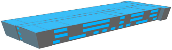
Figure 1.
DeST building model of staff dormitory.
In order to better evaluate the influence of outdoor weather conditions on SHS, the envelope parameters in the three cities are set as constant values to avoid the influence on heat load. The specific parameters are as follows:
- (a)
- Structural parameters: The material parameter settings of the dormitory building’s enclosure and accessories are shown in Table 1 [22]:
 Table 1. Parameter of building enclosure.
- (b)
- Other parameters:
- (1)
- Heating time. The heating date is from November 15th to March 15th of the following year, a total of 120 days.
- (2)
- Indoor personnel. According to the actual construction situation, a total of 456 people live in the building, the density of the number of people in the activity room is 0.1 person/m2.
- (3)
- Lights and equipment. The light power is 11 W/m2, and the equipment power is 20 W/m2.
- (4)
- Room temperature. The room heating temperature is set at 20 °C, and the humidity is 55%.
The purpose of this study is to study the operating status of SHS in cities with different solar energy resource abundance in cold regions of China and to propose optimization strategies. Therefore, Xi’an, Dunhuang, and Lhasa were selected as the representative cities for analysis. The selected cities were divided according to “Design standard for energy efficiency of residential buildings in severe cold and cold zones” JGJ26-2018 [23], and all belong to cold areas in China. In addition, according to the “Technical Standards for Solar Heating and Heating Engineering” GB50495-2019, China’s solar energy resources are divided into four regions, which are: “Resource-richer area (I)”, “Resource-rich area (II)”, ”Resource-general area (Ⅲ)”, and “Resource-poor area (Ⅳ)”. Figure 2a shows the distribution of total annual solar radiation in China. Among them, Xi’an belongs to “Resource-general area (Ⅲ)”, Dunhuang belongs to “Resource-rich area (II)”, and the Lhasa area belongs to “Resource-richer area (I)” [24].
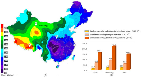
Figure 2.
(a) Distribution map of total annual solar radiation in China; (b) daily average solar radiation and heating load on slope.
After simulation and calculation using DeST software, as shown in Figure 2b, in Xi’an, Dunhuang, and Lhasa, the average daily solar radiation on the inclined planes is 11.7 MJ/m2, 17.5 MJ/m2, and 20.0 MJ/m2, respectively. The seasonal maximum load values are 160.44, 218.67, and 143.91 kW, and the maximum heating load is 63.85 W/m2, 87.02 W/m2, and 57.27 W/m2. The solar energy resources are in the order of Lhasa, Dunhuang, and Xi’an from large to small, and the heating load is in the order of Dunhuang, Xi’an and, Lhasa from large to small.
3. Design and Simulation of SHS
3.1. System Parameters
According to [24], the solar collector angle is suggested equal to the local latitude when it is used all year round and 10 more than the local latitude when it is used in winter. Therefore, the solar dip angles of the three selected regions in this paper are respectively Xi’an (45°), Dunhuang (50°), and Lhasa (40°).
Based on the parameters of Xi’an, the dormitory building is designed and calculated. The design parameters are shown in Table 2.
Table 2.
SHS Parameter calculation table of the dormitory building.
3.2. Conceptual Plan and Dynamic Simulation of SHS
The heating system designed in this study is solar energy—auxiliary heat source heating system (as shown in Figure 3b), and TRNSYS is used as the platform to achieve system simulation through building and combining various modules (as shown in Figure 3a). This system comprises a solar collecting system, a thermal storage system, and an indoor heating system. The solar heat collection system is the main heat source to which an AHS is added.
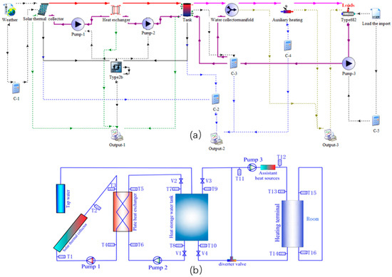
Figure 3.
(a) TRNSYS dynamic simulation flow chart; (b) structure diagram of SHS.
If the water in the storage tank reaches indoor heating temperature, the heat can be supplied directly to the room. If the water temperature in the hot water storage tank is not up to the requirements, heat is supplemented by AHS. If the water tank is lower than heating return water temperature, the heating return water directly enters the AHS for reheating.
The model is established in the TRNSYS software, the parameters including the local weather data, solar radiation of inclined plan, and hourly heating load, and the design parameters of components are imported to obtain the dynamic simulation coupling model. The dynamic coupling model is calculated to obtain various parameters that characterize the performance of the system, such as fluid temperature, flow rate, and AHS heating capacity. The system designed in this study and the dynamic coupling model built in TRNSYS software are consistent with the system used in the study of the author in the last paper [25]. The effectiveness of the system and model in design and computation has been demonstrated in previous research works.
4. Operation Analysis and Optimization
4.1. Analysis of Operation Status of Xi’an
According to the preliminary design conditions, the supply water temperature of floor radiation is 45 °C. Considering the placement of the roof area, 120 collectors were arranged, with an effective heat collecting area of 1.92 m2 for each collector. Each four collectors are connected in series as a group. According to [24], each square meter collector is matched with 100 L HSWT, and the total volume of the tank is 25 m3.
Figure 4 shows the operation status of Xi’an. Figure 4b shows the proportion of water tank temperature in different intervals during heating operation. The temperature of the water tank at 0–40 °C is 6 h, accounting for 0.21%; the temperature of the water tank at 40–45 °C is 2308 h, the proportion is 79.47%; the temperature of the water tank that reaches the heating requirement above 45 °C is 590 h, accounting for 20.32%, and showing in Figure 4a, the temperature of the HSWT has increased significantly after February. The main reason is that the temperature of the surrounding environment rises after the weather gets warmer, which reduces the heat loss of the collector.
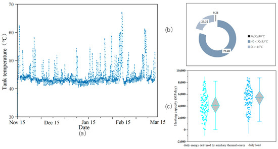
Figure 4.
(a) Hourly change curve of the temperature of the HSWT; (b) the proportion of the temperature of the HSWT; (c) statistic of the daily heat supply of the AHS and the daily load of the building.
Figure 4c is a statistic of the daily heat supply of the AHS and the daily heat supply required by the building during the heating season. The average daily heating capacity is 5339.59 MJ/day, while the average daily heating capacity of the AHS is 4189.82 MJ/day, which accounts for about 78.27% of the heating requirement.
4.2. Optimization Strategy in Xi’an
Heat for SHS comes from AHS and HSWT. Among them, the heat provided by the heat storage tank comes from the solar collector. The ratio of this to the total heat demand of the building is defined as the energy saving rate. Therefore, the state of the SHS can be quantitatively analyzed by using the daily heating load of the building and the daily heat supplied by the AHS. The contribution ratio of solar energy to the heating system can be determined to determine whether SHS is suitable for the building. In order to further improve the contribution rate of solar energy, the temperature of supply and return water and the size of HSWT were optimized, respectively, under the condition that the system structure and other equipment parameters not be changed.
4.2.1. Optimization of Supply Water Temperature
Figure 5 shows the proportion of the water temperature of the HSWT in each interval during the whole heating season when the designed water supply temperature of the SHS is 45, 40, and 35 °C. When the temperature of the water supply is 40 °C, the temperature of the HSWT is in the range of 0~35 °C for a total of 5 h, accounting for 0.17% of the heating time; the temperature is in the range of 35~40 °C for a total of 2258 h, accounting for 77.75%; the temperature of the water tank is up to 641 h above 40 °C, accounting for 22.08%. When the designed water supply temperature is 35 °C, the temperature of the HSWT is between 0 and 30 °C for a total of 5 h, accounting for 0.17% of the heating time; and the temperature is between 30 and 35 °C for a total of 2204 h, accounting for 75.9%; the temperature of the water tank is above 35 °C for 695 h, accounting for 23.93%. Through comparison, after lowering the design water supply temperature, the proportion of time for the water tank temperature to meet the heating requirements has increased from 20.32% to 23.93%, and the utilization rate of the HSWT has gradually increased.
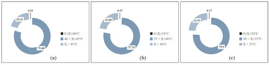
Figure 5.
The proportion of the temperature of the HSWT under different designed water supply temperatures: (a) 45 °C; (b) 40 °C; (c) 35 °C.
Figure 6 shows the proportions of heat supplied by the AHS and the water storage tank, and a box chart of daily energy delivered by the AHS at different water supply temperature. When the design water supply temperature is 45, 40, and 35 °C, the average daily heat supply of the AHS corresponds to 4179.50 MJ/day, 4074.41 MJ/day, and 3966.70 MJ/day. The proportion of heat supplied by the corresponding AHS is 78.27%, 76.31%, and 74.29%, respectively, so the proportion of heat supplied by the HSWT is 26%, 29%, and 31%. The solar energy utilization rate is higher for the system with a water supply temperature of 35 °C, and its solar energy contribution rate can reach 25.71%.
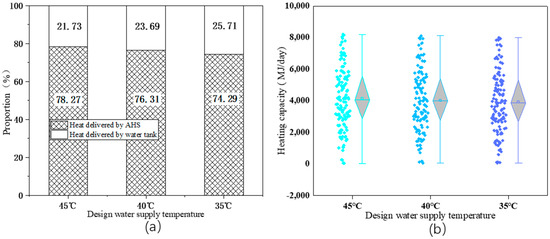
Figure 6.
Under different water supply temperatures: (a) the proportion of heat provided by the AHS and the HSWT; (b) the daily heat supply statistics of the AHS.
The main reason is that the lower the water supply temperature of the system, the easier it is for the HSWT to reach the water supply temperature, thus reducing the AHS opening time. Moreover, after HSWT transfers heat to the back water of the terminal system, the water temperature in the water tank decreases, and the temperature difference between it and the outlet temperature of the collector increases, which enhances the heat exchange effect of the plate heat exchanger to a certain extent and further improves the utilization effect of solar energy. To sum up, for the three design water supply temperatures, the operating effect and energy-saving of the SHS in the whole heating season are best when the water supply temperature is 35 °C.
4.2.2. System Optimization in Different Specifications of HSWTs
According to the above analysis, the design water supply temperature of the system was optimized to 35 °C. The building characteristics and indoor/outdoor parameters remained unchanged, and the volume size of the HSWT was only changed to analyze the operation conditions of each SHS in the whole heating season.
According to the specification [18], each square meter of collector corresponds to 50 L~150 L of water tank. The model established in this paper has a total heat collection area of 230.4 m2, and the corresponding range of HSWT is 11.52 m3~34.56 m3. HSWT with volumes of 5, 10, 15, 20, 25, 30, 35, and 40 m3 were selected near the recommended interval. In order to further evaluate the influence of HSWT volume on heating effect, water tank volumes of 80, 90, and 100 m3 were added as comparison conditions. Other parameters of the system remained unchanged, and the same building was heated for 24 h, with floor radiation at the end. The building is analyzed for the operation of the whole year, and the best selection of HSWT is discussed.
Figure 7 shows a SHS with different specifications of HSWTs. The block diagram of the daily heat supply of the AHS and the percentage of heat are provided by the HSWTs throughout the heating season. The volume of the HSWT increases from 5 m3 to 40 m3, the average daily heat supply of the AHS is 4028.96 MJ/day, 3966.91 MJ/day, 3956.28 MJ/day, 3959.40 MJ/day, 3966.70 MJ/day, 3975.09 MJ /day, 3985.74 MJ/day, and 3999.34 MJ/day. Meanwhile, the proportion of heat supplied by the HSWT in the entire heating season increases from 24.546% (5 m3 water tank) to 25.907% (15 m3 water tank), and then gradually decreases to 25.1% (40 m3 water tank). However, when the volume of the HSWT continues to increase to 80, 90, and 100 m3, the average daily heat supply of the AHS is 4077.19 MJ/day, 4106.27 MJ/day, and 4136.716 MJ/day. The proportion of heat supply of the water storage tank in the whole heating season continues to decline 23.006%, 22.456%, and 21.882%, respectively. Thus, it can be seen that the change in the volume of the HSWT has a certain impact on the proportion of heat supply until the end. When the volume of the water tank is in the range recommended by the specification, its influence is not very great, but there is an optimal value interval. If the volume of the water tank continues to increase after leaving the optimal interval, the heating ratio of the water tank will decrease instead and will continue to decline.
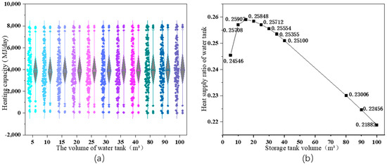
Figure 7.
SHS with different specifications of HSWTs: (a) a block diagram of the daily heat supply of AHS; (b) the proportion of heat provided by the HSWTs throughout the heating season.
The main reason is that in this study, the SHS runs 24 h without interruption. When the volume of the water tank is too small, the heat storage is less than the total heat transferred by the heat exchanger, and the heat collected by the solar collectors cannot be used effectively, resulting in heat loss. Therefore, if the volume of the water tank is increased at this time, the proportion of the HSWT heating in the whole heating season will also increase. When the volume of the HSWT reaches a certain critical point, the heat storage of the water tank is consistent with the heat that the collector supplies to the water tank through the heat exchanger, and the system is in equilibrium. At this time, the heating proportion of the water tank reaches the maximum, that is, the energy saving effect of the system is optimal. If the volume of the water tank continues to increase, its heat storage will increase; the time for the water body to be heated to the required heating temperature will become longer, and the proportion of the time to reach the required heating temperature in the whole heating season will also decrease. In this way, the proportion of heat provided by the HSWT in the whole heating season will decrease.
According to the simulation results, when the HSWT volume is gradually increased from 5 m3 to 40 m3, the heating ratio of the water tank with a water tank volume of 15 m3 reaches the maximum value of 25.907%. Therefore, it is considered that in Xi’an, when the water supply temperature of the building is 35 °C, a HSWT with a volume of 15 m3 is the best choice.
4.3. Comparative Analysis of the Three Regions
In order to explore the solar energy application in different regions, the geographic and meteorological parameters are changed at the same building design of SHS. The tree typical cities of Xi’an, Dunhuang, and Lhasa were selected to optimize the SHS in terms of heating temperature and HSWT volume, and the solar energy contribution rate is analyzed for each region.
Figure 8a shows the optimization analysis of HSWTs in Xi’an, Dunhuang, and Lhasa of the SHS when the terminal water supply temperature is 35 °C during the entire heating season. It can be seen that with the increase in regional solar energy resource abundance, the optimal volume of HSWT also increases. The optimal volume of the HSWT in Xi’an is 15 m3; the optimal volume of the HSWT in Dunhuang area is 25 m3, and the optimal volume of the HSWT in the Lhasa area is 40 m3. After optimizing the design of the water supply temperature and the volume of the HSWT, the energy saving rate of the entire SHS increased significantly. Figure 8b shows the comparison of the final optimization results, and the proportion of heat provided by the HSWT is 25.9%, 32.8%, and 61.3%, respectively. It can be seen that the contribution rate of solar energy in the three regions from high to low is Lhasa, Dunhuang, Xi’an.
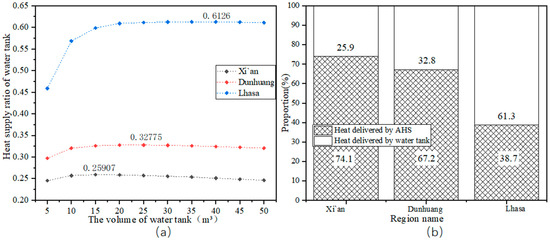
Figure 8.
(a) Optimization analysis of HSWTs in different regions; (b) comparison of final optimization results.
5. Conclusions
A DeST of dormitory building model and a TRNSYS dynamic simulation model of the SHS have been established, according to the simulation data, represented by three typical cities (Xi’an, Dunhuang, and Lhasa) with different solar energy resource abundance. The paper analyzes the running state of SHS in a student dormitory building in a cold area of our country and carries out the corresponding optimization strategy. Our research indicates that the decrease in the temperature of the water supply will enhance the operation and energy-saving effect of the SHS. This is mainly because the lower the designed water supply temperature, the easier it is for the HSWT to reach the water supply temperature, thereby reducing the opening time of the AHS, and the lowering of the inlet and outlet water temperature of the solar collector also further improves the solar heat collection efficiency. There is an optimal value for the volume of the HSWT, which can make the energy-saving effect of the SHS run better. When the volume is too small, it is not enough to store the solar heat collection. When the volume is too large, the temperature of the water tank rises too slowly, prolonging the opening time of the AHS. The optimization strategy of SHS for a student dormitory building in a cold area of China is developed: the water supply temperature is 35 °C; the optimal volume of HSWT is 15 m3 in the “Resource-general area (Ⅲ)” represented by Xi’an, 25 m3 in the “Resource-rich area (Ⅱ)” represented by Dunhuang, and 40m3 in the “Resource-richer area (Ⅰ)” represented by Lhasa. With the increase of the abundance of solar energy resources in the region, the optimal volume of HSWT also increases. This is because as the abundance of solar energy increases; more heat is collected by the collectors, and larger heat storage tanks are needed to store it. Meanwhile, the solar energy contribution rate of the three regions in descending order is 61.3% (Lhasa), 32.8% (Dunhuang), and 25.9% (Xi’an). After optimization, the contribution of SHS increased by about 5%. The system optimization effect of the research results is not significant, but it improves the utilization efficiency of SHS to some extent and makes the system more efficient and energy saving in its operation process. Meanwhile, determining the optimal volume of the HSWT can help to avoid the waste of material cost caused by the large tank when designing the SHS. At present, in the cold areas of north China, many towns and villages do not yet have central heating. Optimizing SHS can broaden the application scope and achieve energy conservation and emissions reduction.
Author Contributions
Data curation, B.Z.; Formal analysis, Y.B.; Methodology, J.G.; Project administration, J.Z.; Resources, T.Q. and S.Y.; Supervision, P.L. All authors have read and agreed to the published version of the manuscript.
Funding
Supported by the Open Project Program of Engineering Research Center of Building Energy Efficiency Control and Evaluation, Ministry of Education under Grant No. AHJZNX-2021-07; Supported by the National Natural Science Foundation of China No. 52208125.
Conflicts of Interest
The authors declare no conflict of interest.
Nomenclature
| Supply temperature of fluid, °C | Maximum thermal load, kW | ||
| Design temperature difference of plate heat, °C | Specific heat capacity of the solution at the collector side, J (kg·K) | ||
| Heat transfer coefficient, W/(m2∙°C) | Specific heat capacity of solution at the end of plate heat exchanger, J (kg·K) | ||
| Area of the plate heat exchanger, m2 | Solution density at collector side, kg/m3 | ||
| Area of single plate heat collector, m2 | Solution density at the end of plate heat exchanger, kg/m3 | ||
| N | Number of heat collectors | Volume of water tank, m3 | |
| Angle of heat collectors, ° | HSWT | Heat storage water tank | |
| Total flow of collector side, kg/s | SASHP | Solar air source heat pump | |
| Total flow at the end of plate heat exchanger, kg/s | AHS | Auxiliary heat source | |
| Thermal efficiency of collector with as reference, % | SHS | Solar heating system | |
| Collector thermal efficiency when = 0, % | , | Heat source, load side flow, kg/h | |
| Normalized temperature difference, (m2·K)/W | , | Tank Heat Loss Coefficient | |
| Constant with reference to | Tank Heat Loss Coefficient | ||
| Constant with reference to | Ambient temperature, °C | ||
| G | Total solar irradiance, W/m2 | , | Heat source, load Control parameters |
| Collector working medium inlet temperature, °C | , | Control parameters of heat and mass exchange between layers i | |
| Ambient temperature, °C | Tank top temperature, | ||
| The i-th water layer mass, kg | Design heating temperature, °C | ||
| The i-th water layer temperature, °C | Heating backwater temperature, °C | ||
| Specific heat capacity of water, kJ/(kg·K) | M | Hot water flow, kg/h | |
| Flow of heating backwater back to water tank, kg/h | Flow of heating backwater directly into mixing valve, kg/h |
References
- Francesconi, M.; Antonelli, M. A CFD analysis to investigate thermal losses in a panel composed of several CPC concentrators. Therm. Sci. Eng. Progr. 2018, 5, 278–288. [Google Scholar] [CrossRef]
- Kılıçkap, S.; El, E.; Yıldız, C. Investigation of the effect on the efficiency of phase change material placed in solar collector tank. Therm. Sci. Eng. Progr. 2018, 5, 25–31. [Google Scholar] [CrossRef]
- Yu, H.; Niu, J.L.; Chung, T.M. Study on performance of energy-efficient retrofitting measures on commercial building ex-ternal walls in cooling-dominant cities. Appl. Energy 2013, 103, 97–108. [Google Scholar]
- Zou, B.; Dong, J.K.; Yao, Y.; Jiang, Y.Q. An experimental investigation on a small-sized parabolic trough solar collector for water heating in cold areas. Appl. Energy 2016, 163, 396–407. [Google Scholar] [CrossRef]
- Sun, L.; Xiang, N.; Yuan, Y.P.; Cao, X.L. Experimental Investigation on Performance Comparison of Solar Water Heating-Phase Change Material System and Solar Water Heating System. Energies 2019, 12, 2347. [Google Scholar] [CrossRef]
- Hu, W.S.; Sun, S.J.; Zhang, C.J.; Xiong, C.; Sun, P.F. Performance of phase—Variant U—tube solar collector. Chem. Ind. Eng. Prog. 2021, 40, 771–777. [Google Scholar]
- de Araújo Elias, T.; da Costa Mendes, P.R.; Normey-Rico, J.E. Hybrid predictive controller for overheating prevention of solar collectors. Renew. Energy 2019, 136, 535–547. [Google Scholar] [CrossRef]
- Kaan, Y.; Gökhan, A. Modeling, simulation, and optimization of a solar water heating system in different climate regions. J. Renew. Sustain. Energy 2018, 10, 3703. [Google Scholar]
- Kursun, B.; Okten, K. Effect of rectangular hot water tank position and aspect ratio on thermal stratification enhancement. Renew. Energy 2018, 116, 639–646. [Google Scholar] [CrossRef]
- Rey, A.; Zmeureanu, R. Multi-objective optimization of a residential solar thermal combisystem. Sol. Energy 2016, 139, 622–632. [Google Scholar] [CrossRef]
- Hui, D. Optimization Design and Operation Simulation of Solar Heating System in Jinzhou Xinwande Co., Ltd; Liaoning University of Technology: Jinzhou, China, 2018. [Google Scholar]
- Wu, W.; Dai, S.; Liu, Z.; Dou, Y.P.; Wang, X.Y. Experimental study on the performance of a novel solar water heating system with and without PCM. Sol. Energy 2021, 171, 604–612. [Google Scholar] [CrossRef]
- Wang, D.; Gao, Q.; Liu, Y.; Wang, Y.; Chen, Y.W.; Liu, Y.; Liu, J.P. Experimental study on heating characteristics and parameter optimization of transpired solar collectors. Appl. Energy 2019, 238, 534–546. [Google Scholar] [CrossRef]
- Villasmil, W.; Troxler, M.; Hendry, R.; Schuetz, P.; Worlitschek, J. Control strategies of solar heating systems coupled with seasonal thermal energy storage in self-sufficient buildings. J. Energy Storage 2021, 42, 103069. [Google Scholar] [CrossRef]
- Zhang, L.; Chen, H.; Liu, C.; He, Y.; Cao, L. Optimal allocation of heat collection area of two kinds of collectors in solar water heating system. Mod. Electron. Tech. 2021, 44, 156–159. [Google Scholar]
- Varc, P.; Seidl, J.; Václav, D. Experimental study of influence of inlet geometry on thermal stratification in thermal energy storage during charging process. Eur. Phys. J. Conf. 2014, 67, 02114. [Google Scholar]
- Erdemir, D.; Altuntop, N. Improved thermal stratification with obstacles placed inside the vertical mantled hot water tanks. Appl. Therm. Eng. 2016, 100, 20–29. [Google Scholar] [CrossRef]
- Moncho-Esteve, I.J.; Gasque, M.; González-Altozano, P.; Palau-Salvador, G. Simple inlet devices and their influence on thermal stratification in a hot water storage tank. Energy Build. 2017, 150, 625–638. [Google Scholar] [CrossRef]
- Liu, Y.F.; Li, T.; Chen, Y.W.; Wang, D.J. Optimization of Solar Water Heating System under Time and Spatial Partition Heating in Rural Dwellings. Energies 2017, 10, 1561. [Google Scholar] [CrossRef]
- Huan, C.; Sheng, L.; Zhao, W. Performance Analysis of a Combined Solar-Assisted Heat Pump Heating System in Xi’an, China. Energies 2019, 12, 2515. [Google Scholar] [CrossRef]
- Long, J.; Xia, K.; Zhong, H.; Lu, H.; Yongga, A. Study on energy-saving operation of a combined heating system of solar hot water and air source heat pump. Energy Convers. Manag. 2021, 229, 113624. [Google Scholar] [CrossRef]
- GB50736-2018; Ministry of Housing and Urban-Rural Development of the People’s Republic of China. Design Code for Heating Ventilation and Air Conditioning of Civil Buildings. China Architecture & Building Press: Beijing, China, 2018.
- JGJ26-2018; Ministry of Housing and Urban-Rural Development of the People’s Republic of China. Design Standard for Energy Efficiency of Residential Buildings in Severe Cold and Cold Zones. China Architecture & Building Press: Beijing, China, 2018.
- GB 50495-2019; Ministry of Housing and Urban-Rural Development of the People’s Republic of China. Technical Standards for Solar Heating and Heating Engineering. China Architecture & Building Press: Beijing, China, 2019.
- Zhao, J.; Bai, Y.; Gao, J.; Qiang, T.; Liang, P. Smart Evaluation Index of Roof SHS Suitability. Energies 2022, 15, 1164. [Google Scholar] [CrossRef]


Publisher’s Note: MDPI stays neutral with regard to jurisdictional claims in published maps and institutional affiliations. |
© 2022 by the authors. Licensee MDPI, Basel, Switzerland. This article is an open access article distributed under the terms and conditions of the Creative Commons Attribution (CC BY) license (https://creativecommons.org/licenses/by/4.0/).