Article

Fracture Mechanism of Crack-Containing Strata under Combined Static and Harmonic Dynamic Loads Based on Extended Finite Elements

1
State Key Laboratory of Shale Oil and Gas Enrichment Mechanisms and Effective Development, Beijing 102206, China
2
Institute of Petroleum Engineering, Northeast Petroleum University, Daqing 163318, China
*
Author to whom correspondence should be addressed.
Energies 2022, 15(21), 7940; https://doi.org/10.3390/en15217940
Submission received: 11 September 2022 / Revised: 19 October 2022 / Accepted: 21 October 2022 / Published: 26 October 2022
(This article belongs to the Special Issue Optimization and Simulation of Intelligent Oil and Gas Wells)

Abstract

:
Based on the existing research results, a theoretical fracture model of strata under the compound impact of static and harmonic dynamic load is improved, and the fracture characteristic parameters (stress intensity factor, T-stress, and fracture initiation angle) under the two far-field stress are determined according to the crack dip angle. Additionally, the effects of harmonic dynamic load on the distribution of the stress field and the fracture characteristic (the crack initiation angle, the fracture degree, the number of fracture units, and the fracture area) are further calculated and discussed by theoretical model solution, extended finite element simulation, and the secondary development of the simulation module, respectively. The research results show that the far-field stress, stress intensity factor, and T-stress vary in harmonic form with time under the compound impact of static and harmonic dynamic loads. The frequency of dynamic load affects the number of reciprocal fluctuations of stress intensity factor and T-stress as well as the crack initiation time, but has less influence on the crack initiation angle and fracture degree. While the amplitude of dynamic load affects the stress intensity factor, the extreme value of T-stress and fracture characteristics of the crack. This study has theoretical guiding significance for parameters’ optimization and realization of resonance impact drilling technology.

1. Introduction

In engineering practice, many problems in engineering fields are related to the damage mechanism or process of rocks under combined static and dynamic loading, such as safe and efficient mining of ore rocks, anti-cracking design of rock engineering, controlled blasting technology, stone processing technology, and earthquake engineering, etc. Therefore, it is important to clarify the mechanics and damage characteristics of rocks under combined static and dynamic loading to solve and optimize engineering practice operations [1,2,3,4].
In the field of oil drilling, the static-dynamic load composite impact action is widely used in the rock-breaking process due to its better breaking efficiency compared to the single static load action [5,6]. Therefore, a series of drilling speed-up tools such as self-excited oscillatory impactors, jet impactors [7,8,9] and various efficient rock-breaking methods such as resonance impact drilling technology [10,11,12] have been generated. Resonance impact drilling technology is a drilling technology that achieves efficient rock breaking by impacting the formation rock with a composite of axially static and harmonic dynamic loads to make the rock resonant in conjunction with drilling pressure and rotational speed. Unlike the conventional static-dynamic loads’ coupling action that characterizes the dynamic load by the impact velocity, resonance impact drilling technology considers the amplitude and frequency of dynamic loads as the characteristic parameters [13,14].
It is well known that rock mass is a discontinuous medium with multiple cracks, joints and faults, which are the source of new fractures. Under the action of various external loads, new cracks will sprout, expand, and continuously connect with the original and new cracks, thus eventually leading to the volumetric destruction of the rock [15,16]. Since the process of crack initiation and expansion is complex and not easy to observe, the numerical simulation method is usually used to analyze the fracture process of rocks in the engineering field.
Currently, the common numerical calculation methods used to simulate rock fracture and extension include finite element method, extended finite element method, boundary element method, discrete element method, etc. [17,18,19]. Among them, the traditional finite element method has good generality and theoretical basis, but it also has the disadvantages of complicated pre-processing when dealing with static cracks and weak ability to deal with dynamic cracks. Compared with the finite element method, the boundary element method simplifies the preprocessing to a certain extent and the approximate solution is more accurate, but it is difficult to solve and difficult to deal with larger scale problems, so its application is limited. The discrete element method is more effective in dealing with discontinuous problems, but for continuous problems, the computational effort increases exponentially, resulting in lower computational efficiency. Extended finite element is one of the superior numerical simulation methods to simulate crack expansion [20,21]. Since the core idea of this method is to represent the discontinuity in the computational region by using the shape function with discontinuous nature of the expanded band, it can solve the discontinuity problems that require constant mesh reconstruction or large computational effort due to the fine gridding division for the traditional element method. It not only inherits the advantages of traditional finite elements in solving crack expansion problems, but also can greatly save computational time and improve computational accuracy [22,23].
Resonance impact drilling technology is a cutting-edge high-efficiency rock-breaking technology. The research on it mainly focuses on the deformation characteristics and resonant characteristics of the rock, the dynamic characteristics and drilling efficiency of the impact system, however, its rock-breaking mechanism is not yet perfect, especially the fracture mechanism of the formation under the compound impact of static and harmonic dynamic loads which is a key problem that is yet to be solved. Therefore, this paper considers the crack structure of the rock and utilizes the advantages of extended finite element simulation for fracture expansion to carry out the fracture mechanism of strata under the compound action of static and harmonic dynamic loads, to clarify the effect of the frequency and amplitude of harmonic dynamic load on the fracture characteristics of rock crack, to provide a theoretical basis for parameter optimization, and further promote the application of resonance impact drilling technology.
The paper is organized as follows: In Section 2, physical and mathematical models of fracture mechanism of strata with harmonic vibration impact are proposed. In Section 3, based on the theoretical model, the influence of harmonic dynamic load on the key parameters of fracture initiation and expansion is discussed. Then, the simulation of the fracture process of strata containing the crack under the compound impact of static and dynamic loads through the extended finite element method and the secondary development of the module is conducted in Section 4. Finally, the limitations of this study and the prospect of future work are discussed in Section 5.

2. Strata Fracture Mechanism under Harmonic Vibration Impact

2.1. Physical Model

In order to analyze the fracture mechanism of the strata under harmonic vibration impact, the force model is presented as shown in Figure 1. Considering the actual strata is unbounded and referring to the analysis method of stress field in classical elasticity [24], the stratum is assumed to be a semi-infinite elastic plane, and a rectangular coordinate system is established with its center point as the coordinate origin O. The axial static load Fs and the harmonic dynamic load Fd = Fcos ωt are simultaneously applied to the stratum at the center position.
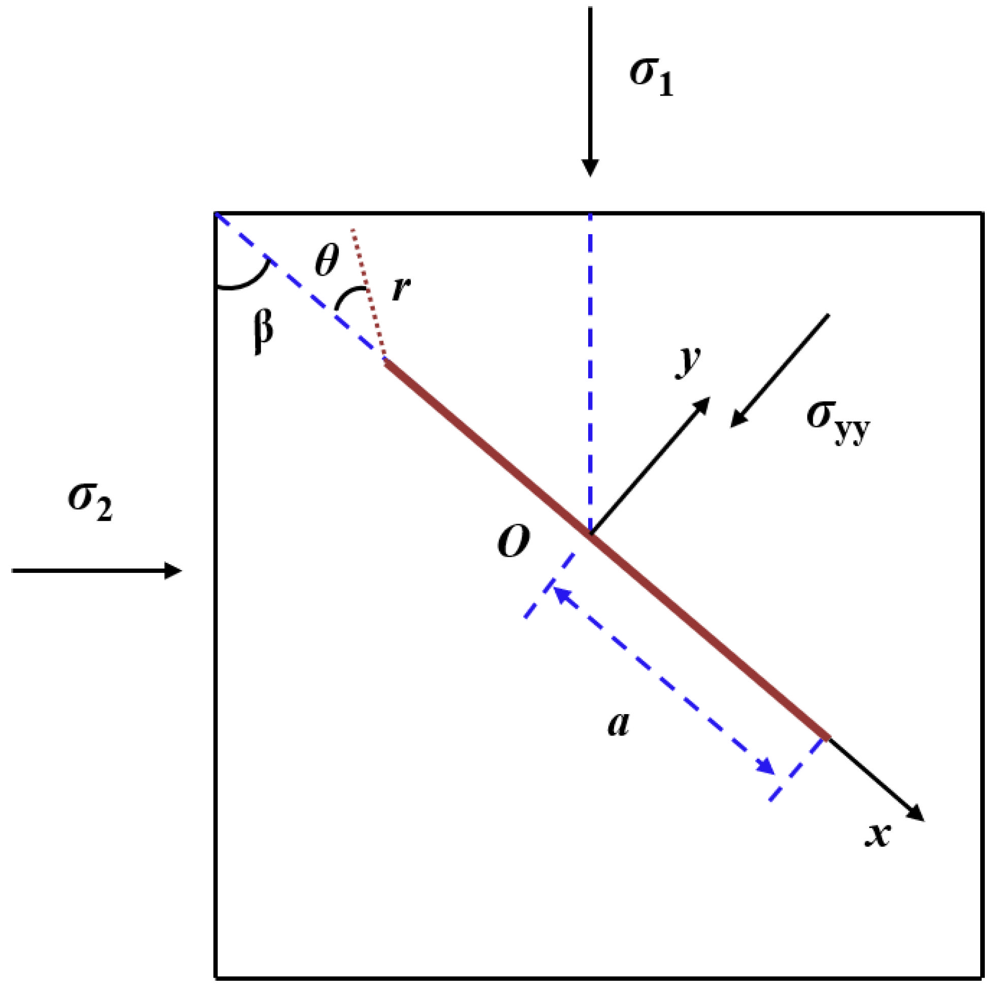
Suppose there is a single crack in the strata, and its position can be represented by the rotation angle φ which is determined by the counterclockwise rotation of the Y-axis to the crack. The angle between the crack and the vertical direction is the crack dip angle, denoted by β, the length of the crack is 2a, and the initiation angle of the crack tip is θ. A local rectangular coordinate system is established with the crack center O as the origin, the crack direction as the x-axis, and the direction perpendicular to the crack as the y-axis, as shown in Figure 2.

2.2. Mathematical Model

The compound impact of static and harmonic dynamic loads on the strata can be regarded as a special case of arbitrary load intruding into the strata. One reason is that the applied combined force is axial, i.e., there is no angle with the strata. The other reason is that although harmonic dynamic load is a quantity that changes with time, it can be regarded as a static load per unit time, so the force on the strata in the unit time can be regarded as the combined force of two static loads. At this time, the stress field at the crack in the stratum due to the external load action is the far-field stress field, and according to the existing research results [25], the far-field stress at any crack within the formation under the combined action of static and dynamic loads can be expressed as:
σ x = 2 F π cos 3 φ x 2 + y 2
σ y = 2 F π cos φ sin 2 φ x 2 + y 2
σ x y = 2 F π cos 2 φ sin φ x 2 + y 2
where F = F s + F d = F s + F cos ω t is the resultant force applied to the strata, N; x, y are the horizontal and vertical distances of the crack from the coordinate origin, respectively, m; the negative sign indicates the compressive stress.
The far-field principal stress to which the crack is subjected are σx and σy, respectively, but which of them is the positive stress σ1 acting on the crack surface depends on the magnitude of σx and σy, and it is related to the crack rotation angle φ. Therefore, it can be discussed as follows:
(1)
When 0 < |φ| < π/4, |σx| > |σy|, then σx is the positive stress σ1, and the crack dip angle β is π/2 − φ.
Based on the available research results, the stress intensity factor KII at the tip of the crack can be given as:
K II = 2 F a π cos 3 φ x 2 + y 2 ( 1 λ ) sin φ cos φ μ cos 2 φ + λ sin 2 φ
where λ = σ y σ x = sin 2 φ cos 2 φ , μ is the Coulomb friction coefficient.
The T-stress at the tip of the crack is:
T x = 4 F π cos 3 φ sin 2 φ x 2 + y 2
T y = 2 F π cos φ x 2 + y 2 cos 4 φ + sin 4 φ
The crack initiation angle θ at the tip of the crack satisfies the following equation [26]:
3 cos θ 1 cos θ 2 8 3 μ l β y cos 2 θ 4 3 β x β y l sin 2 θ = 0
where l = 2 r c a , rc is the critical distance of crack initiation.
β x = sin 2 φ + λ cos 2 φ ( 1 λ ) sin φ cos φ - μ cos 2 φ + λ sin 2 φ
β y = cos 2 φ + λ sin 2 φ ( 1 λ ) sin φ cos φ - μ cos 2 φ + λ sin 2 φ
(2)
When π/4 < |φ| < π/2, |σy| > |σx|, then σy is the positive stress σ1, and the crack dip angle β is φ.
The stress intensity factor KII at the crack tip is:
K II = 2 F a π cos φ sin 2 φ x 2 + y 2 ( 1 λ ) sin φ cos φ μ sin 2 φ + λ cos 2 φ
where: λ = σ x σ y = cos 2 φ sin 2 φ .
The T-stress at the tip of the crack is:
T x = 4 F π cos 3 φ sin 2 φ x 2 + y 2
T y = 2 F π cos φ x 2 + y 2 sin 4 φ + cos 4 φ
The crack initiation angle also satisfies Equation (7):
β x = cos 2 φ + λ sin 2 φ ( 1 λ ) sin φ cos φ - μ sin 2 φ + λ cos 2 φ
where:
β y = sin 2 φ + λ cos 2 φ 1 λ sin φ cos φ μ sin 2 φ + λ cos 2 φ

3. Analysis of Influencing Factors

3.1. Effects of Harmonic Dynamic Load on Far-Field Stress

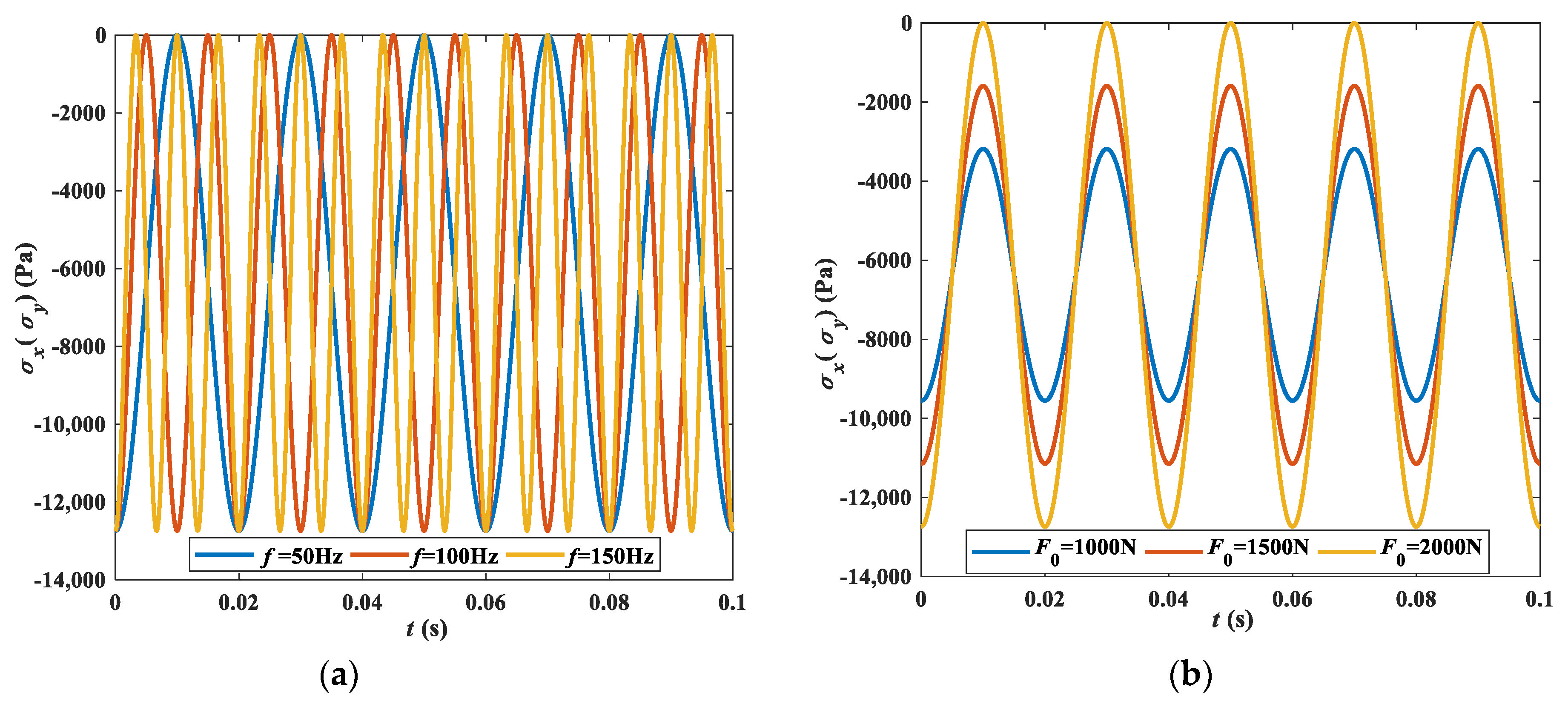
As shown in Figure 3, the harmonic dynamic load makes the far-field stress at which the crack is located also vary in harmonic form compared to the action of a single static load, and it no longer remains constant with time. In the same time, the variation of the frequency of dynamic load changes the reciprocation times of far-field stress fluctuation, and the variation of the amplitude of dynamic load changes the extreme value of far-field stress. The larger the impact frequency is, the more far-field stress reciprocal cycles are, the larger the impact amplitude is, the greater the far-field stress maximum value and the smaller the minimum value are. It should be noted here that the magnitude of the applied dynamic load should be smaller than the static load to ensure that the far-field stress in the crack is always under the condition of ballast.
Since the harmonic dynamic load is a periodic load that varies with time, the magnitude of the far-field stress is not constant when the time is at different moments of the harmonic cycle. Here, a cosine harmonic dynamic load is applied with an impact frequency of 50 Hz. The dynamic loads are 0, peak unloaded, and peak loaded when t = 0.005 s, t = 0.01 s, and t = 0.02 s, respectively. Therefore, the corresponding far-field stress magnitudes, both σx and σy, reach a minimum at t = 0.01 s, a maximum at t = 0.02 s, and are in the middle at t = 0.005 s, as shown in Figure 4. In addition, by comparing the variation curves of far-field stress σx and σy with the rotation angle φ under the same conditions, it can be seen that σx decreases with the increase of φ, while σy increases and then decreases with the increase of φ. When φ = 45°, σx and σy intersect, as shown by the black dashed line in Figure 4, where σx > σy on the left side and σx < σy on the right side.

3.2. Effects of Harmonic Dynamic Load on Stress Intensity Factor KII

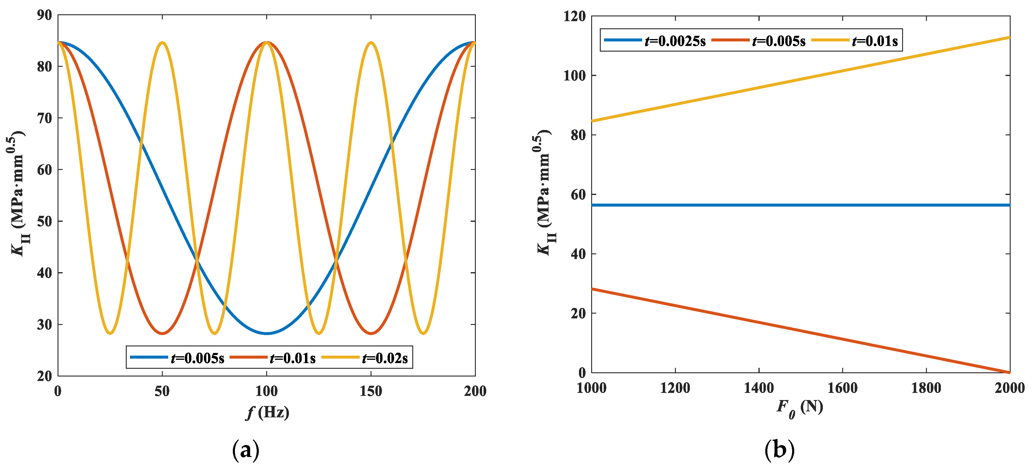
The variation curves of stress intensity factor with the frequency and amplitude of dynamic load at different moments are given in Figure 5, respectively. As shown in Figure 5a, with the change of the frequency of dynamic load, the stress intensity factor at the crack tip also takes the form of harmonic wave motion. The stress intensity factor fluctuates with different periods at different moments, but the change in time and frequency did not change its peak magnitude. From Figure 5b, it can be seen that the stress intensity factor at the crack tip increases or decreases linearly or remains constant with the increase of the amplitude of dynamic load at different moments. The reason for this phenomenon depends on whether the analysis moment corresponds to the loading or unloading phase of the harmonic dynamic load. In this analysis, since the frequency of dynamic load is 100 Hz, t = 0.0025 s, t = 0.005 s, and t = 0.01 s correspond to the three cases of harmonic dynamic load of 0, unloading peak, and loading peak, respectively, which leads to the variation results in Figure 5b.

3.3. Effects of Harmonic Dynamic Load on T-Stress

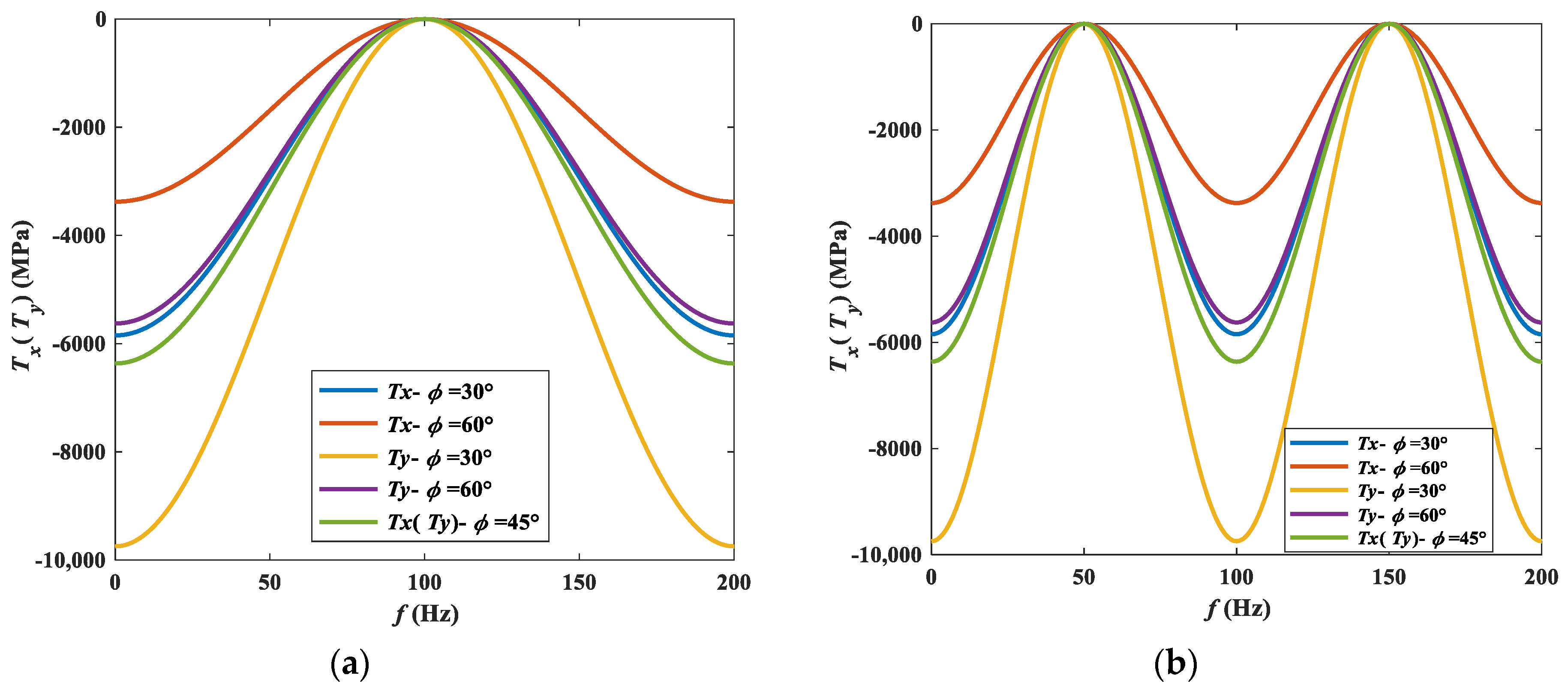
Figure 6 shows the variation between T-stress and impact frequency with static load of 1 kN, dynamic load amplitude of 1 kN, and different rotation angle φ. As shown in the figures, T-stress varies in harmonic form with the change of impact frequency. With the rotation angle φ increasing, Tx increases and then decreases, and Ty decreases. When φ = 45°, Tx = Ty. As can be seen from Figure 6a, when f = 100 Hz, Tx and Ty are 0. This is due to the fact that when t = 0.005 s, the harmonic dynamic load reaches the reverse peak, at which time, the combined force acting on the strata is 0, and no stress field is generated. In the same principle, when t = 0.01 s, the T-stress at f = 50 Hz and 150 Hz is corresponding to 0, as shown in Figure 6b. In addition, by comparing Figure 6a,b, it can be found that the period of T-stress reciprocating with the frequency of dynamic load is different for different calculation moments.
Figure 7 shows the variation between T-stress and the amplitude of dynamic load with the impact frequency of 100 Hz, static load of 2 kN, and other conditions which are the same as above. As shown in Figure 7a, the T-stress decreases linearly with the increase of dynamic load amplitude during the unloading stage at t = 0.005 s, and finally decreases to 0. At this time, the dynamic load reaches the peak of unloading, and the static and dynamic loads cancel each other. In the other unloading stages, the T-stress decreases similarly, only with different magnitudes. As shown in Figure 7b, the T-stress increases linearly with the increase of dynamic load amplitude at t = 0.01 s when the loading is at the peak stage. Similarly, the magnitude of T-stress loading is different for different loading stages. In addition, Tx increases and then decreases with the increase of rotation angle φ, and Ty decreases with both loading and unloading phases.

4. Numerical Simulation

4.1. Modeling

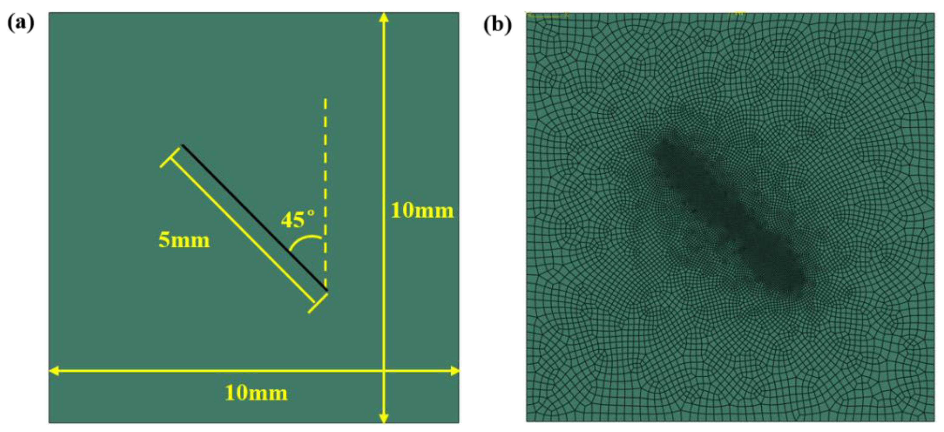
To further analyze the expansion characteristics of the crack within the strata under harmonic dynamic load, the extended finite element (XFEM) method is used to simulate the dynamic expansion of the crack in this paper. Since the XFEM does not need to deal with the details of the structure when dealing with discontinuous problems, but only considers the overall geometry of the structure and then generates an adaptive finite element mesh, the specific modeling method is as follows: the strata model is a cube of 10 mm × 10 mm × 0.5 mm, which contains a rectangular crack of 5 mm × 0.5 mm and the crack dip angle of 45°, as shown in Figure 8a. The global mesh size of the model is divided into 0.3 mm, and then the crack part is locally encrypted with the size of 0.05 mm, so as to ensure that the mesh precision will no longer have an impact on the simulation results. Here, the type of grid cell is selected as hexahedron and the entire model is meshed by sweeping, then a total of 10,760 units are generated. Full fixed constraints are applied to the bottom surface of the model, as shown in Figure 8b. The stratigraphic material is limestone which is set to elastic, and its physical and mechanical property parameters are obtained from indoor experimental tests, which are as follows: density is of 2.75 × 10⁻⁹ t/mm3, elastic modulus is of 51,500 MPa, and Poisson’s ratio is of 0.33. The Maxps Damage is chosen as the damage criterion, where the max principal stress is 120 MPa, the displacement at failure is 0.01, and the viscosity coefficient is 5 × 10⁻⁵. In the simulation, the applied frequency range of harmonic dynamic load is 50~100 Hz, the amplitude is 100~500 N, and the static load is 500 N. The principle of determining the frequency and amplitude of dynamic load is to ensure the convergence of the model calculation within the achievable range of the experimental setup. The simulation calculation time is set to 0.02 s so that the harmonic dynamic load of all frequencies can be applied for at least one full cycle.

4.1.1. Effects of Harmonic Dynamic Load on Stress Field

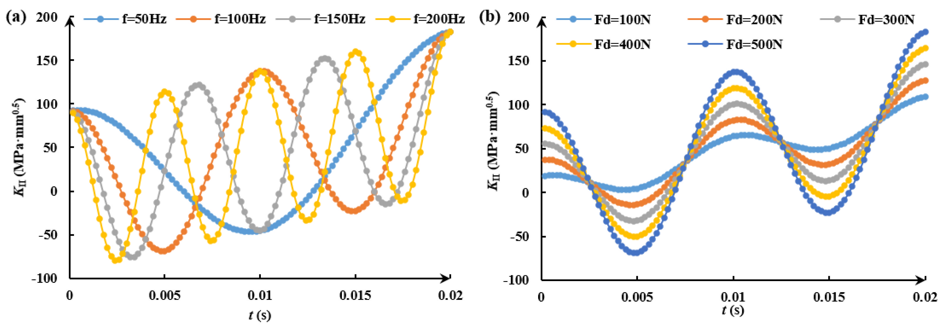
As shown in Figure 9 and Figure 10, the stress intensity factor and T-stress at the crack tip under different harmonic dynamic load conditions show the same variation law with time; only the magnitude is different, so the stress intensity factor is taken as an example for analyzing. As shown in Figure 9, due to the existence of harmonic dynamic load, the stress intensity factor at the crack tip fluctuates with time in a harmonic form whether the frequency or the amplitude of dynamic load changes. In the time of 0.02 s, with the frequency of dynamic load increases from 50 Hz to 200 Hz, the number of fluctuation periods of stress intensity factor increases from 1 to 4, as shown in Figure 9a. With the amplitude of dynamic load increases from 100 N to 500 N, the value of stress intensity factor increases at the same time, as shown in Figure 9b. It can be seen that the numerical simulation results are basically consistent with the conclusions of the theoretical analysis. However, there is a slight difference that the extreme values of the stress intensity factor under different harmonic dynamic loads remain constant with time in the theoretical model analysis, while in the numerical simulation, it shows a linear increasing change with the increase of time. It is mainly caused by the fact that the theoretical study is performed as a single point calculation, while the numerical simulation is performed as a continuous calculation.

4.1.2. Effects of Harmonic Dynamic Load on the Fracture Degree of Crack

In order to further analyze the influence law and degree of harmonic dynamic load on crack initiation and propagation, the module is secondly developed on the basis of XFEM function to realize the extraction of crack geometric parameters such as the number of fracture unit and fracture area. Thus, the fracture characteristics of strata can be understood more comprehensively and intuitively.
(1)
The frequency of dynamic load
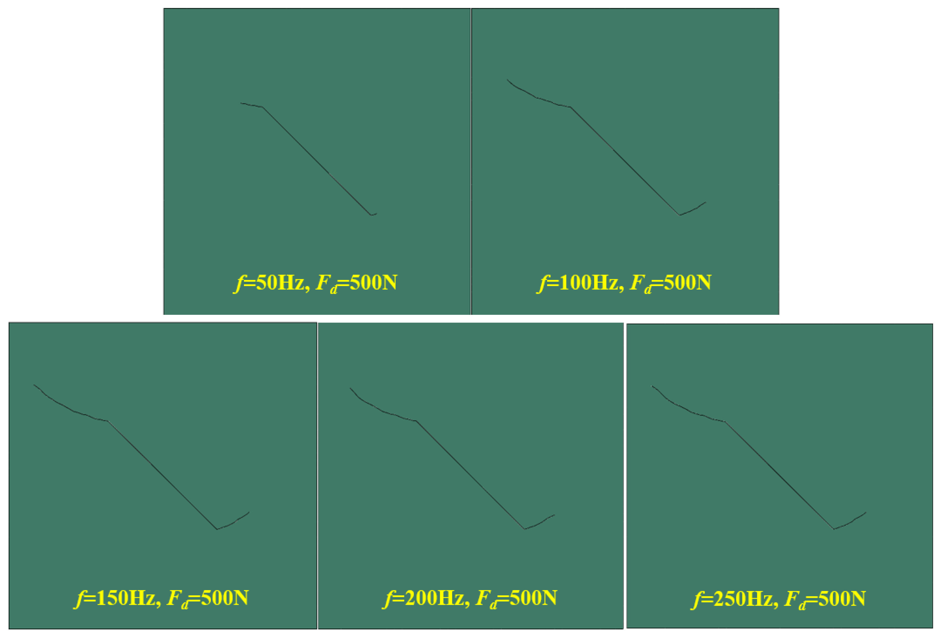
Figure 11 and Figure 12 show the fracture degree of the crack within the strata at different frequencies of dynamic load with a static load of 500 N and impact amplitude of 500 N. As shown in Figure 11, with the increase of the frequency of dynamic load, the initiation angle and propagation degree of the crack are basically consistent (except for 50 Hz). From the previous theoretical model, it is known that the frequency of dynamic load does not affect the initiation angle of the crack, and a similar conclusion is obtained in the numerical simulation results.
We can deduce from the calculation results that when the applied frequencies are 50 Hz, 100 Hz, 150 Hz, 200 Hz, and 250 Hz, the maximum numbers of crack element of the strata are 282, 327, 336, 337, and 341, respectively, and the maximum crack areas are 3.048 mm2, 4.08 mm2, 4.29 mm2, and 4.362 mm2. It can be seen that the number of crack element and the crack area increase with the increase of the frequency of dynamic load, but the growth range of fracture characteristic parameters is small at other frequencies of dynamic load except 50 Hz, as shown in Figure 12. At the initial moment, the initial values of the number of crack element and crack area are the same at different frequencies of dynamic load, which is due to the fact that the load is not applied at this time and the fracture characteristic parameters extracted from the strata are original fracture characteristics. With the increase of time, the number of crack element and the crack area show a stepwise increasing change. The higher the frequency of dynamic load is, the more incremental inflection points are. In addition, the crack initiation times corresponding to the change of the frequency of dynamic load from 50 Hz to 250 Hz are 0.0074 s, 0.0034 s, 0.0022 s, 0.0016 s, and 0.0014 s, which show that the higher the frequency of dynamic load is, the less time is required for crack initiation, and the earlier the crack initiation time is.
(2)
The amplitude of dynamic load
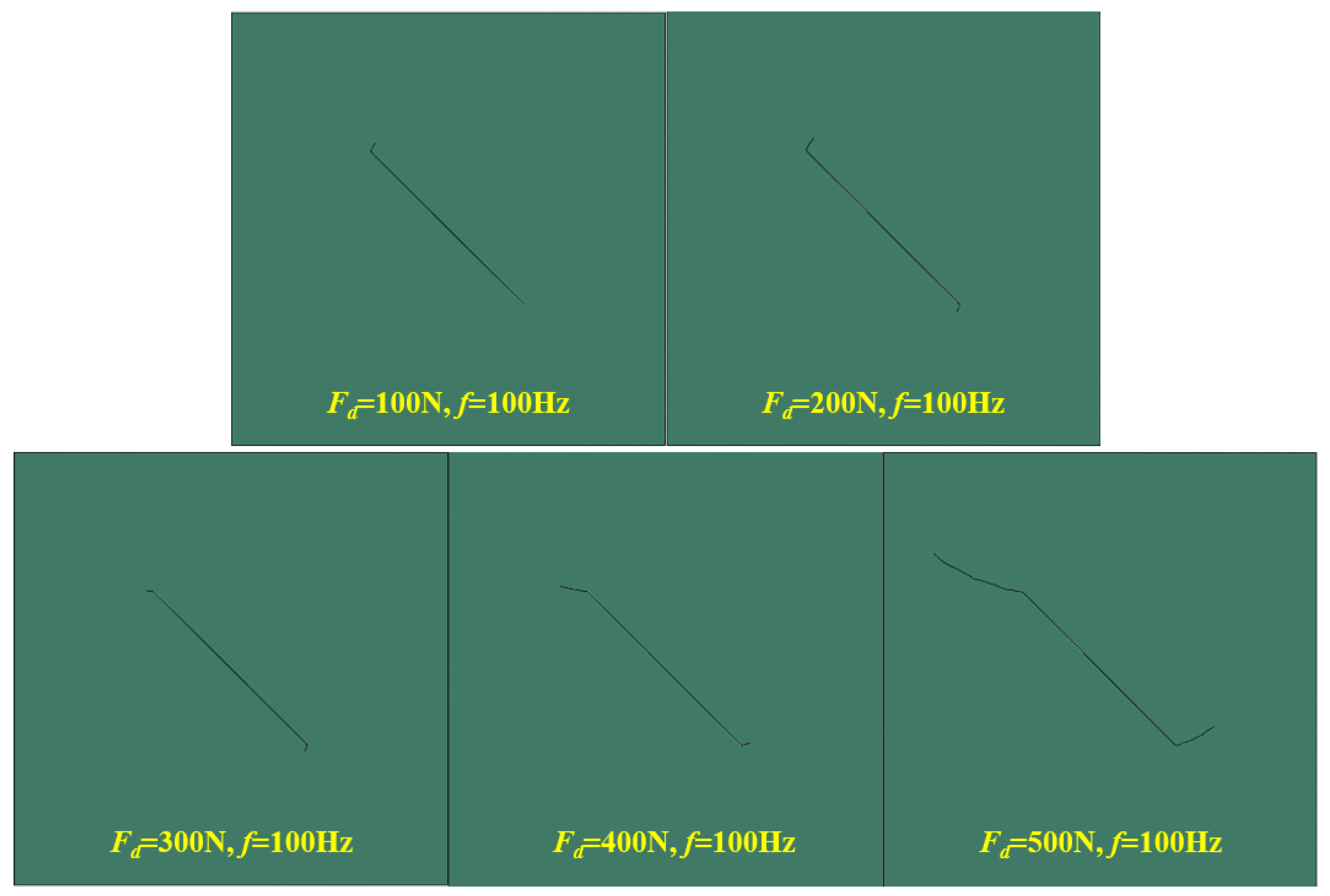
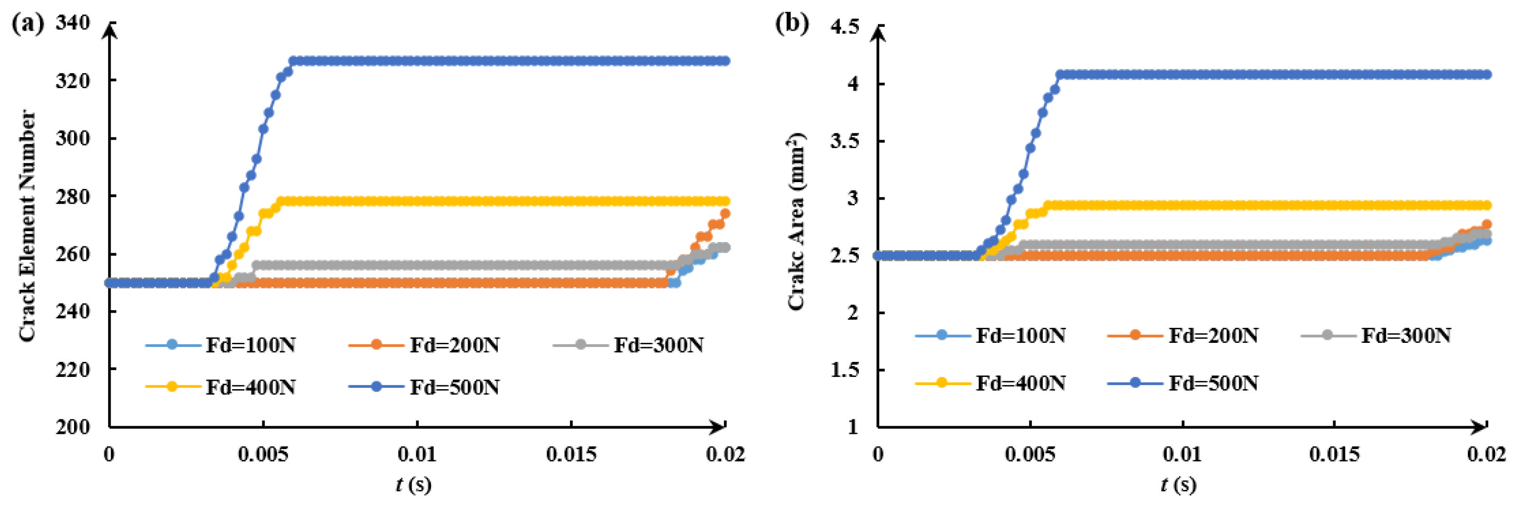
Figure 13 and Figure 14 give the fracture characteristics of the stratigraphic crack under different amplitudes of dynamic load with the static load of 500 N and the frequency of 100 Hz. As shown in Figure 13, with the increase of the amplitude of dynamic load, the fracture degree of the crack is aggravated and the crack extends more widely. In addition, the initiation direction at the two tips of the crack also changes significantly. The effect of the amplitude of dynamic load on crack fracture is more obvious than that of the frequency of dynamic load.
It can be seen from Figure 14 that the number of crack element and the crack area within the strata increase with the increasing of the amplitude of dynamic load. When the amplitude of dynamic load is greater than 300 N, the growth degree of the two fracture characteristic parameters is more obvious. The step times of the two fracture characteristic parameters with time change are basically the same for the same frequency and different amplitude of dynamic load. When the amplitude of dynamic load is less than 300 N, the crack initiation time is about 0.018 s, and when the amplitude is greater than 300 N, the crack initiation time is about 0.004 s, therefore, it can be concluded that the larger the amplitude of dynamic load is, the earlier the crack initiation is.
Based on the analysis of the effects of dynamic load on crack initiation and propagation, it can be seen that the frequency of dynamic load (except for the resonance frequency of strata) has little effect on the fracture degree of crack, and the main effect is on the crack initiation velocity. This is mainly due to the frequency which mainly affects the number of reciprocal vibration of strata, which makes it more likely to fatigue and preferably fracture, while the amplitude of dynamic load has an obvious influence on both the initiation velocity and fracture degree of the crack. This is mainly due to the fact that the magnitude of the external load directly affects the far-field stress of the crack, which in turn affects the fracture characteristics of the crack.

5. Discussion and Outlook

This paper focuses on the effect of harmonic dynamic load on strata fracture, and its significance lies in that it can provide theoretical support for the subsequent parameters’ optimization of resonance impact drilling technology. From this paper, it is clear that both the frequency and amplitude of dynamic load is conducive to crack initiation and propagation, either by accelerating the initiation rate or by aggravating the fracture degree of the crack. However, it is obvious that the frequency and amplitude of dynamic load cannot be increased indefinitely due to the limitation of actual underground conditions, and it also depends on the working performance of the downhole power tool (resonance module).
In addition, it is worth noting that this paper discusses the effect of the frequency of dynamic load on crack only for the general case of resonance drilling technology implementation, and does not take into account the special case of resonance. In fact, the fracture effect would be the best when the strata rock reaches resonance. However, since the problem concerning the resonance frequency of rock is extremely complex and requires further systematic research in the future, it is not discussed in this paper.
In summary, the research results of this paper can provide theoretical support for the design and parameter optimization of resonance modules, which is an indispensable key link in the implementation of resonance drilling technology.

6. Conclusions

  • On the basis of the existing research results, the physical and mathematical models of the strata impacted by harmonic vibration are improved by introducing the harmonic dynamic load. Considering the magnitude of the principal stress in the far- field, the calculation methods of fracture characteristic parameters such as stress intensity factor, T-stress, and crack initiation angle of the stratum under two cases are given.
  • It can be obtained by solving the theoretical model that the harmonic dynamic load makes the far-field stress of the crack also change in harmonic form. The normal stress acting on the crack is different due to the different dip angle of crack. The frequency of dynamic load and time affect the fluctuation number of stress intensity factor and T-stress, and the amplitude of dynamic load and time affect the extreme value and linear trend of stress intensity factor and T-stress.
  • The results obtained from XFEM numerical simulation and module secondary development calculations show that the harmonic dynamic load causes the stress intensity factor and T-stress at the crack tip fluctuating in a harmonic form with time. The frequency of dynamic load has little effect on the fracture degree of the stratum, but has a significant effect on the crack initiation time. The amplitude of dynamic load has a significant effect on the initiation rate, initiation direction, and fracture degree of the crack.

Author Contributions

H.Z. proposed the model; Z.C. analyzed the influencing factors; Y.T. and Z.L. carried out the 3D simulation; S.W. carried out the analysis of simulation results; S.L. wrote the paper. All authors have read and agreed to the published version of the manuscript.

Funding

The support of Enterprise Innovation Development Joint Fund Integration Project: Basic Research Program on Deep Petroleum Resource Accumulation and Key Engineering Technologies (U19B6003) is gratefully acknowledged.

Data Availability Statement

The data presented in this study are available on request from the corresponding author.

Conflicts of Interest

The authors are aware of the ethical responsibilities and they declare that they have no conflict of interest.

References

  1. Jin, J.; Liang, X.Y.; Yang, G.Q.; Zhou, Y.T. Test studies on geogrid-soil interface behavior under static and dynamic loads. Sustainability 2022, 14, 4299. [Google Scholar] [CrossRef]
  2. Kong, P.; Jiang, L.S.; Jiang, J.Q.; Wu, Y.N.; Chen, L.J.; Ning, J.G. Numerical analysis of roadway rock-burst hazard under superposed dynamic and static loads. Energies 2019, 12, 3761. [Google Scholar] [CrossRef] [Green Version]
  3. Li, D.Y.; Xiao, P.; Han, Z.Y.; Zhu, Q.Q. Mechanical and failure properties of rocks with a cavity under coupled static and dynamic loads. Eng. Fract. Mech. 2022, 225, 106195. [Google Scholar] [CrossRef]
  4. Wang, W.; Wang, H.; Li, D.Y.; Li, H.M.; Liu, Z.M. Strength and failure characteristics of natural and water-saturated coal specimens under static and dynamic loads. Shock Vib. 2018, 2018, 3526121. [Google Scholar] [CrossRef] [Green Version]
  5. Zhu, W.C.; Bai, Y.; Li, X.B.; Niu, L.L. Numerical simulation on rock failure under combined static and dynamic loading during SHPB tests. Int. J. Impact Eng. 2012, 49, 142–157. [Google Scholar] [CrossRef]
  6. Li, Y.H.; Peng, J.Y.; Zhang, F.P.; Qiu, Z.G. Cracking behavior and mechanism of sandstone containing a pre-cut hole under combined static and dynamic loading. Eng. Geol. 2016, 213, 64–73. [Google Scholar] [CrossRef]
  7. Aguiar, R.R.; Weber, H.I. Mathematical modeling and experimental investigation of an embedded vibro-impact system. Nonlinear Dyn. 2011, 65, 317–334. [Google Scholar] [CrossRef]
  8. Wang, J.L.; Han, B.; Wang, C.; Gong, Y.J.; Li, Y.S.; Neville, A.; Morina, A. Failure analysis of the piston used in a pneumatic down the hole impactor. Eng. Fall Anal. 2021, 127, 105561. [Google Scholar] [CrossRef]
  9. Wiercigroch, M.; Vaziri, V.; Kapitaniak, M. RED: Revolutionary drilling technology for hard rock formations. In Proceedings of the SPE-184665-MS, SPE/IADC Drilling Conference And Exhibition, The Hague, The Netherlands, 14 March 2017. [Google Scholar]
  10. Pavlovskaia, E.; Hendry, D.C.; Wiercigroch, M. Modelling of high frequency vibro-impact drilling. Int. J. Mech. Sci. 2015, 91, 110–119. [Google Scholar] [CrossRef] [Green Version]
  11. Li, W.; Yan, T.; Li, S.Q. Rock fragmentation mechanisms and an experimental study of drilling tools during high-frequency harmonic vibration. Petrol. Sci. 2013, 10, 205–211. [Google Scholar] [CrossRef]
  12. Li, S.Q.; Vaziri, V.; Kapitaniak, M.; M Millett, J.; Wiercigroch, M. Application of resonance enhanced drilling to coring. J. Petrol. Sci. Eng. 2020, 188, 106866. [Google Scholar] [CrossRef]
  13. Li, S.Q.; Tian, S.L.; Li, W. Numerical study on the elastic deformation and the stress field of brittle rocks under harmonic dynamic load. Energies 2020, 13, 851. [Google Scholar] [CrossRef] [Green Version]
  14. Wiercigroch, M.; Krivtsov, A.M.; Wojewoda, J. Vibrational energy transfer via modulated impacts for percussive drilling. J. Theor. App. Mech. 2008, 46, 715–726. [Google Scholar]
  15. Hoek, E.; Martin, C.D. Fracture initiation and propagation in intact rock: A review. J. Rock Mech. Geotech. Eng. 2014, 6, 287–300. [Google Scholar] [CrossRef] [Green Version]
  16. Wong, L.N.Y.; Einstein, H.H. Crack coalescence in molded gypsum and Carrara marble: Part 1. Macroscopic observations and interpretation. Rock Mech. Rock Eng. 2009, 42, 475–511. [Google Scholar] [CrossRef]
  17. Dmitry, I.G. Cohesive-zone effects in hydraulic fracture propagation. J. Mech. Phys. Solids 2019, 133, 103727. [Google Scholar]
  18. Skopintsev, A.M.; Dontsov, E.V.; Kovtunenko, P.V. The coupling of an enhanced pseudo-3D model for hydraulic fracturing with a proppant transport model. Eng. Fract. Mech. 2020, 236, 107–177. [Google Scholar] [CrossRef]
  19. Zou, Y.; Zhang, S.; Ma, X. Numerical investigation of hydraulic fracture network propagation in naturally fractured shale formations. J. Struct. Geol. 2016, 84, 1–13. [Google Scholar] [CrossRef]
  20. Jiang, Y.; Dong, J.; Nie, D.F.; Zhang, X.Q. XFEM with partial Heaviside function enrichment for fracture analysis. Eng. Fract. Mech. 2021, 241, 107375. [Google Scholar] [CrossRef]
  21. Li, H.; Li, J.S.; Yuan, H. A review of the extended finite element method on macrocrack and microcrack growth simulations. Theor. Appl. Fract. Mec. 2018, 97, 236–249. [Google Scholar] [CrossRef]
  22. Teng, Z.H.; Sun, F.; Wu, S.C.; Zhang, Z.B.; Chen, T.; Liao, D.M. An adaptively refined XFEM with virtual node polygonal elements for dynamic crack problems. Comput. Mech. 2018, 62, 1087–1106. [Google Scholar] [CrossRef]
  23. Chen, J.-W.; Zhou, X.P. The enhanced extended finite element method for the propagation of complex branched cracks. Eng. Anal. Bound. Elem. 2019, 104, 46–62. [Google Scholar] [CrossRef]
  24. Landau, L.D.; Pitaevskii, L.P.; Kosevich, A.M. Theory of Elasticity: Volume 7 (Theoretical Physics), 3rd ed.; Elsevier: Amsterdam, The Netherlands, 2012. [Google Scholar]
  25. Li, S.Q.; Li, W.; Yan, T.; Bi, F.Q.; Zhao, H.; Ling, X. Fracture mechanism of the formation with a natural flaw under a single-tooth cutting. Acta Mech. Solida Sin. 2020, 33, 719–730. [Google Scholar] [CrossRef]
  26. Li, X.F.; Lee, K.Y.; Tang, G.J. Kink angle and fracture load for an angled crack subjected to far-field compressive loading. Eng. Fract. Mech. 2012, 82, 172–184. [Google Scholar] [CrossRef]
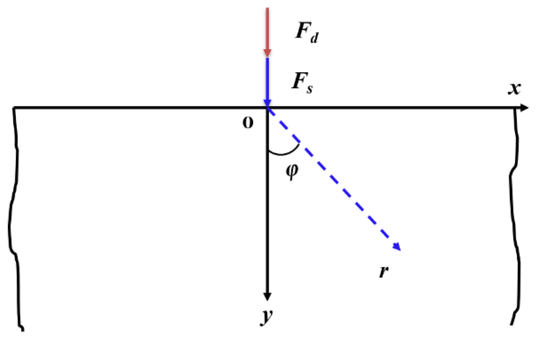
Figure 1. Schematic diagram of harmonic vibration impacting an infinite stratum.
Energies 15 07940 g001
Figure 2. Schematic diagram of the crack contained in the stratum.
Energies 15 07940 g002
Figure 3. Far-field stress variation curves with time under different harmonic dynamic loads: (a) different frequencies; (b) different amplitudes.
Energies 15 07940 g003
Figure 4. Variation curve of far-field stress with crack rotation angle φ at different moments.
Energies 15 07940 g004
Figure 5. Variation of stress intensity factor with harmonic dynamic load at different moments: (a) dynamic load frequency; (b) dynamic load amplitude.
Energies 15 07940 g005
Figure 6. Variation of T-stress with the frequency of harmonic dynamic load at different rotation angles φ: (a) t = 0.005 s; (b) t = 0.01 s.
Energies 15 07940 g006
Figure 7. Variation law of T-stress with the amplitude of harmonic dynamic load at different rotation angles φ: (a) unloading stage at t = 0.005 s; (b) loading stage at t = 0.01 s.
Energies 15 07940 g007
Figure 8. Schematic diagram of the strata model with a crack: (a) model dimensions; (b) meshing.
Energies 15 07940 g008
Figure 9. Variation curves of stress intensity factor at crack tip with time under different harmonic dynamic loads: (a) different frequencies; (b) different amplitudes.
Energies 15 07940 g009
Figure 10. Variation curves of T-stress at crack tip with time under different harmonic dynamic loads: (a) different frequencies; (b) different amplitudes.
Energies 15 07940 g010
Figure 11. Schematic diagram of crack initiation under different frequencies of dynamic load.
Energies 15 07940 g011
Figure 12. Fracture degree of the crack under different frequencies of dynamic load: (a) crack element number; (b) crack area.
Energies 15 07940 g012
Figure 13. Schematic diagram of crack initiation under different amplitudes of dynamic load.
Energies 15 07940 g013
Figure 14. Fracture degree of the crack under different amplitudes of dynamic load: (a) crack element number; (b) crack area.
Energies 15 07940 g014
Publisher’s Note: MDPI stays neutral with regard to jurisdictional claims in published maps and institutional affiliations.