
Development and Evaluation of Large-Size Phase Change Proppants for Fracturing of Marine Natural Gas Hydrate Reservoirs

Abstract
:1. Introduction
2. Development of the Large-Size Resin Phase Change Proppants
2.1. Materials
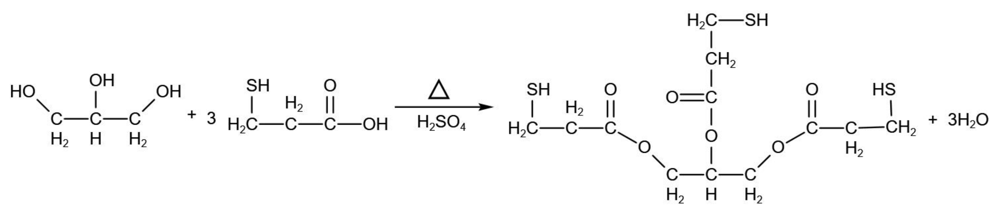
2.2. Synthesis and Characterization of Polythiol Curing Agents
2.3. Optimization of Compound Curing Agent System
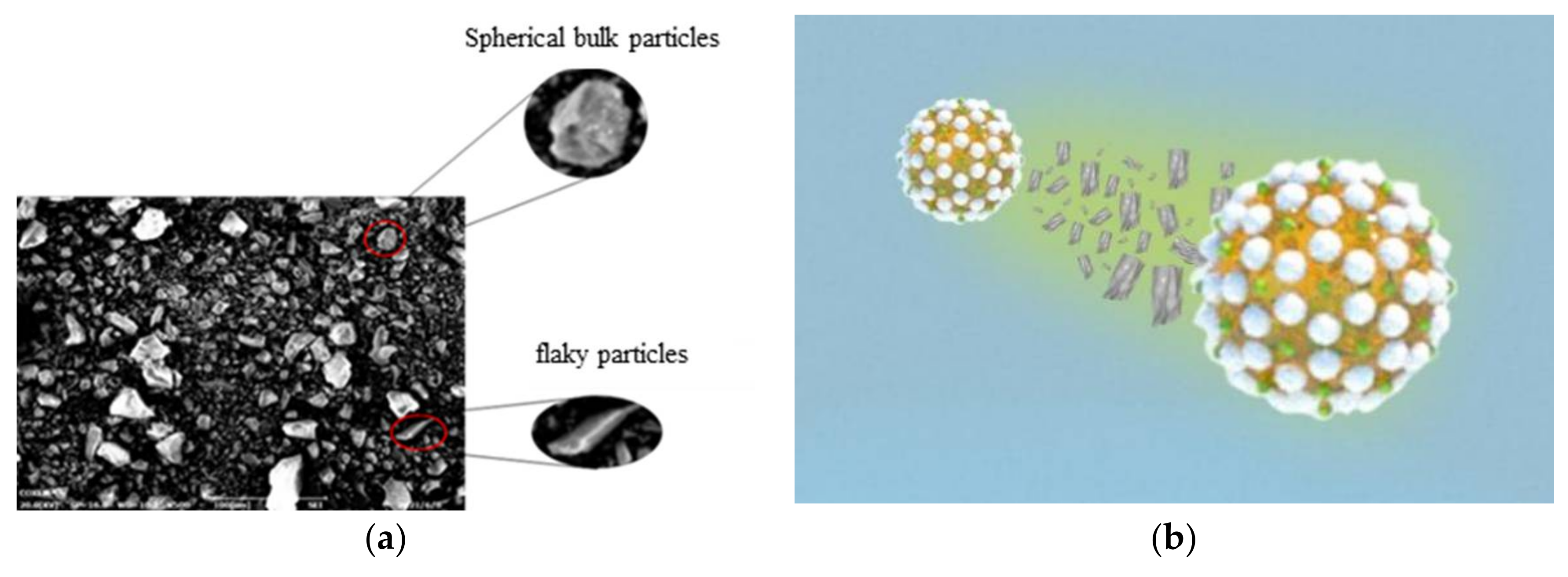
2.4. Selection of Emulsifiers and Emulsification Mechanism Analysis
2.4.1. Selection of the Type of Emulsifier
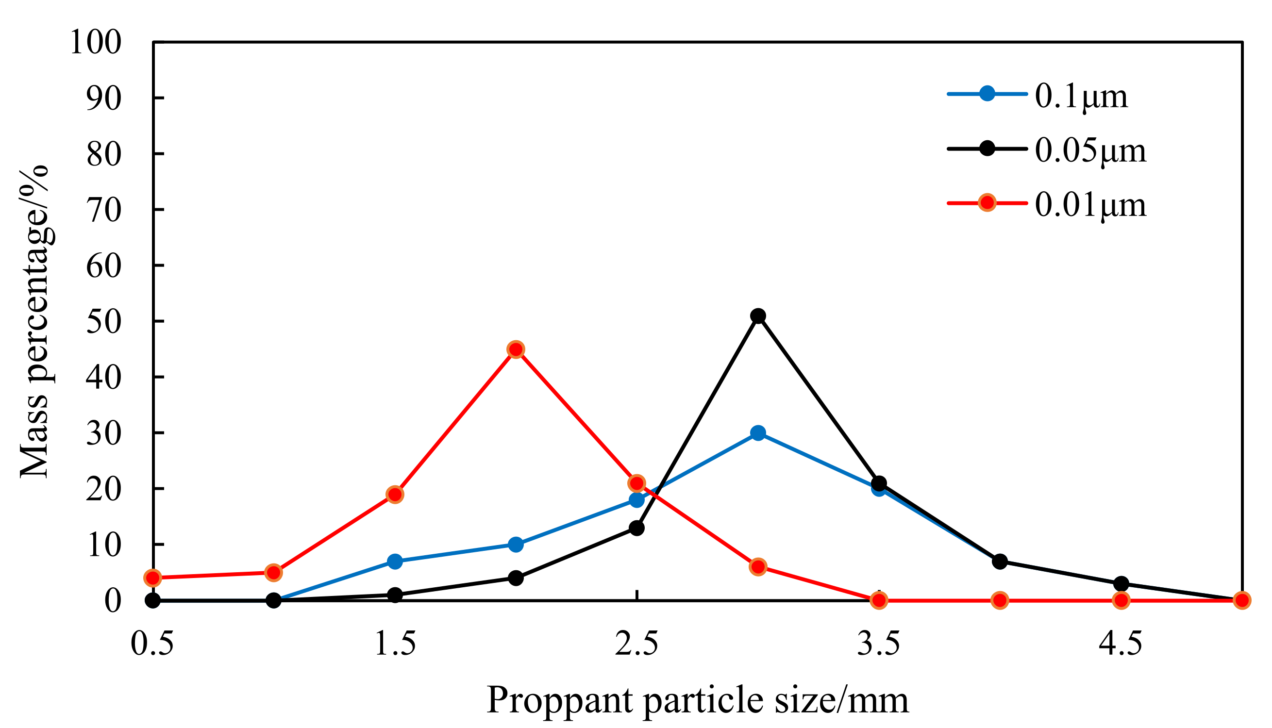
2.4.2. Optimal Particle Size of Emulsifier
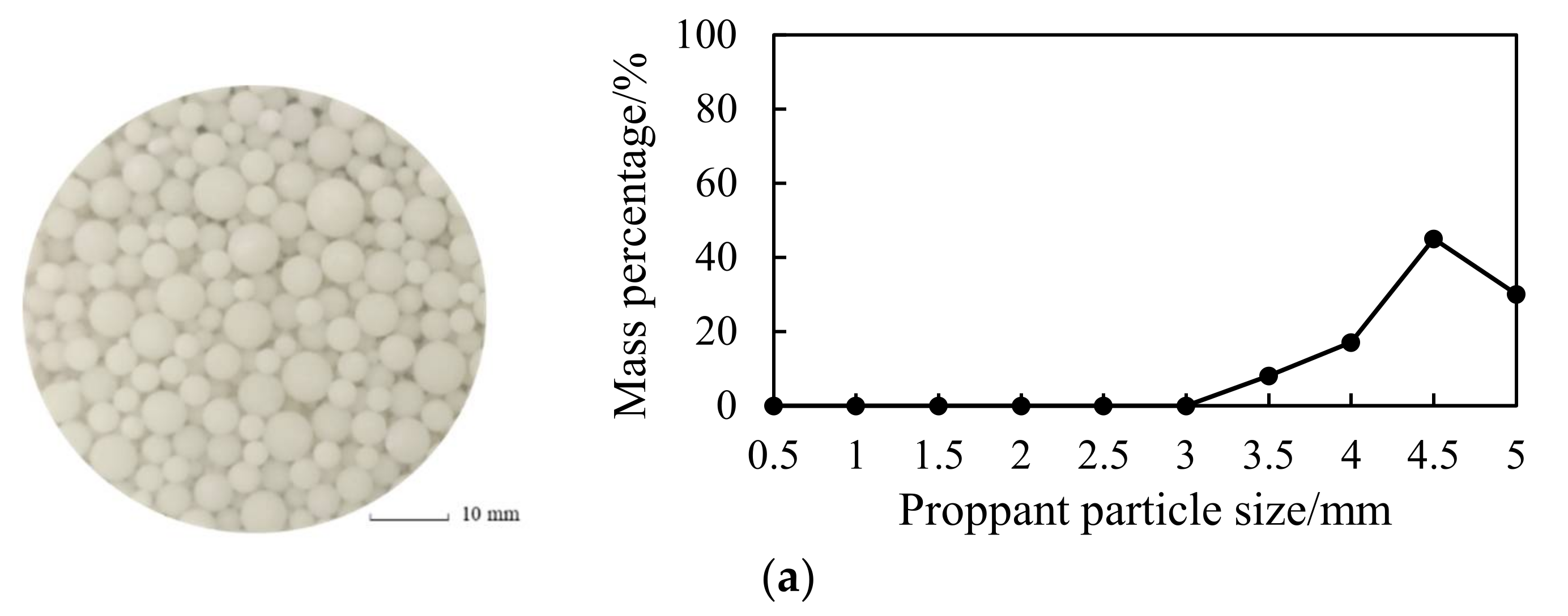
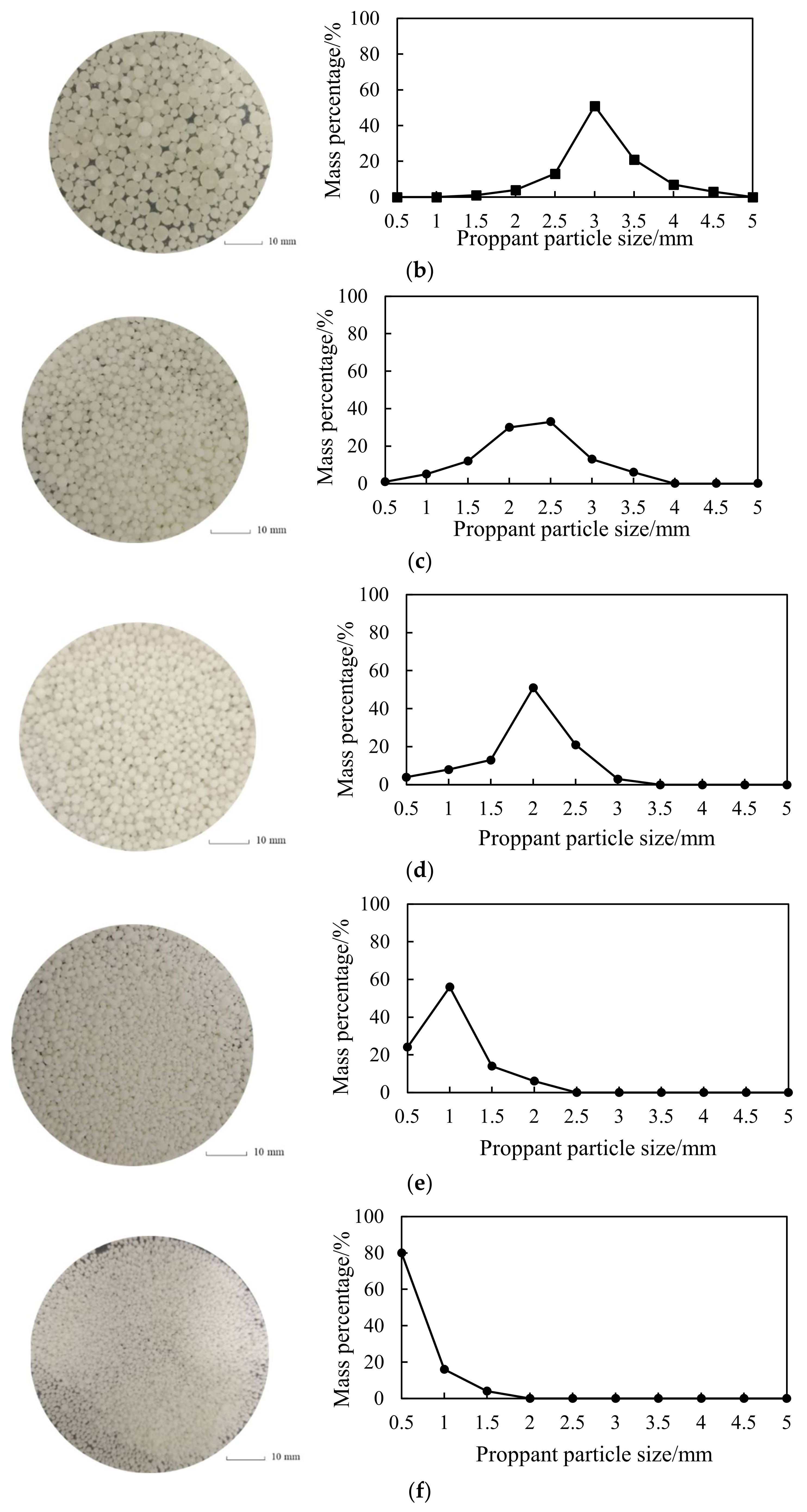
2.5. Controllable Treatment of Proppant Particle Size
2.6. Optimization of Emulsification Process
3. Evaluation Experiment of the Large-Size Resin Phase Change Proppants
3.1. Physical Property Evaluation
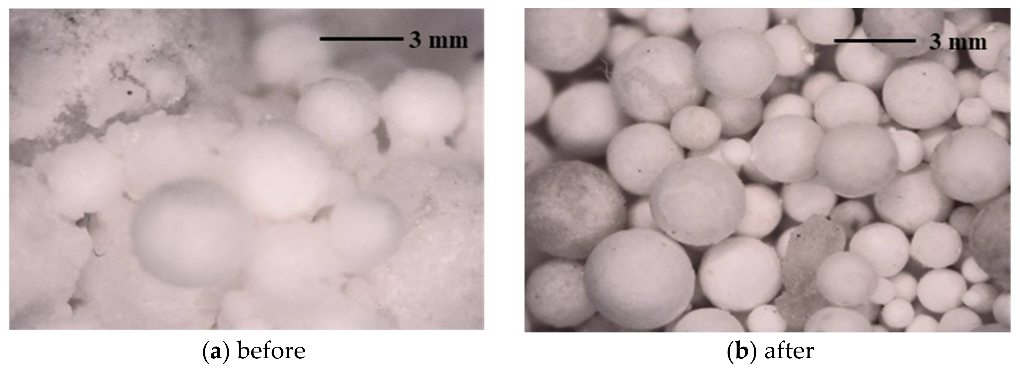
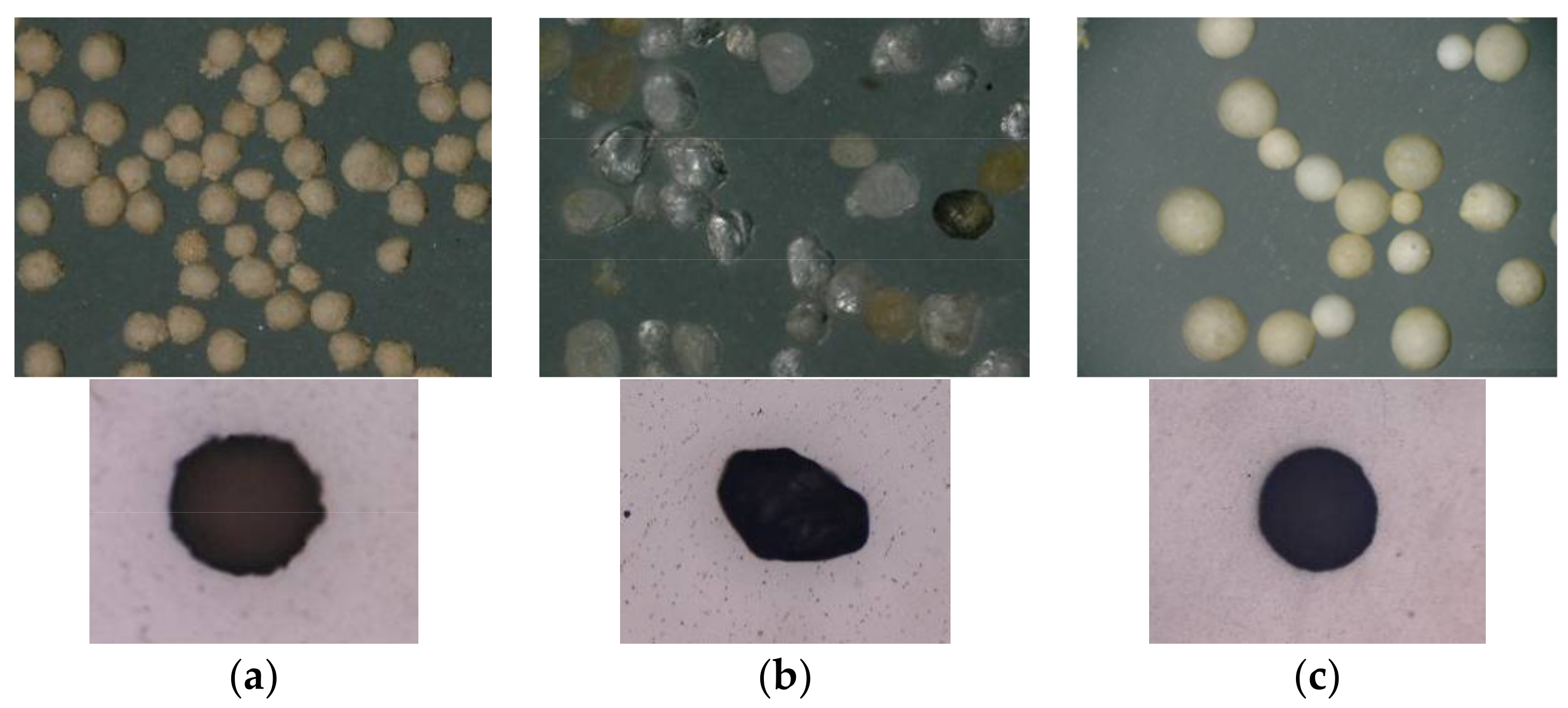
3.1.1. Proppant Morphology
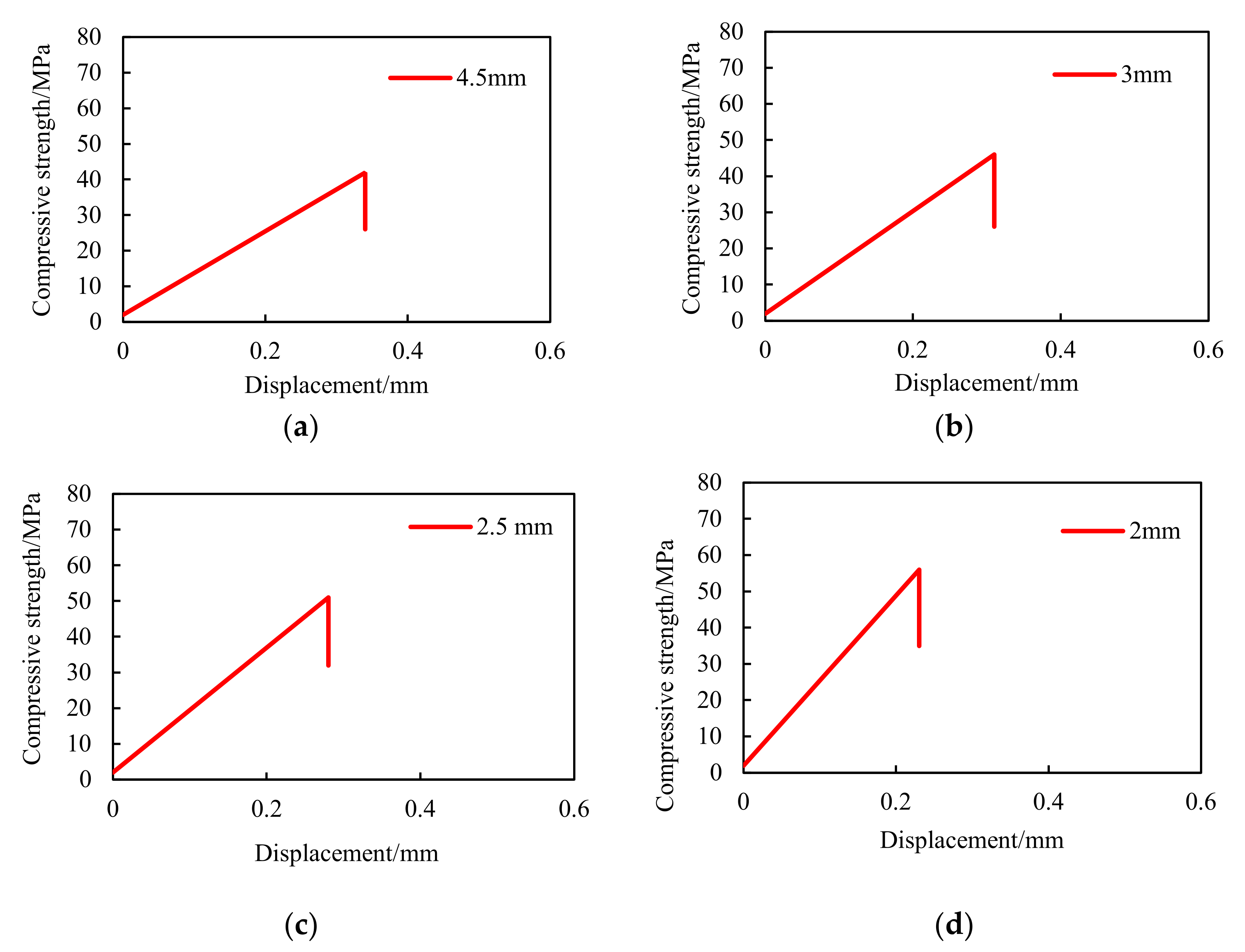
3.1.2. Compressive Strength
3.2. Application Performance Evaluation
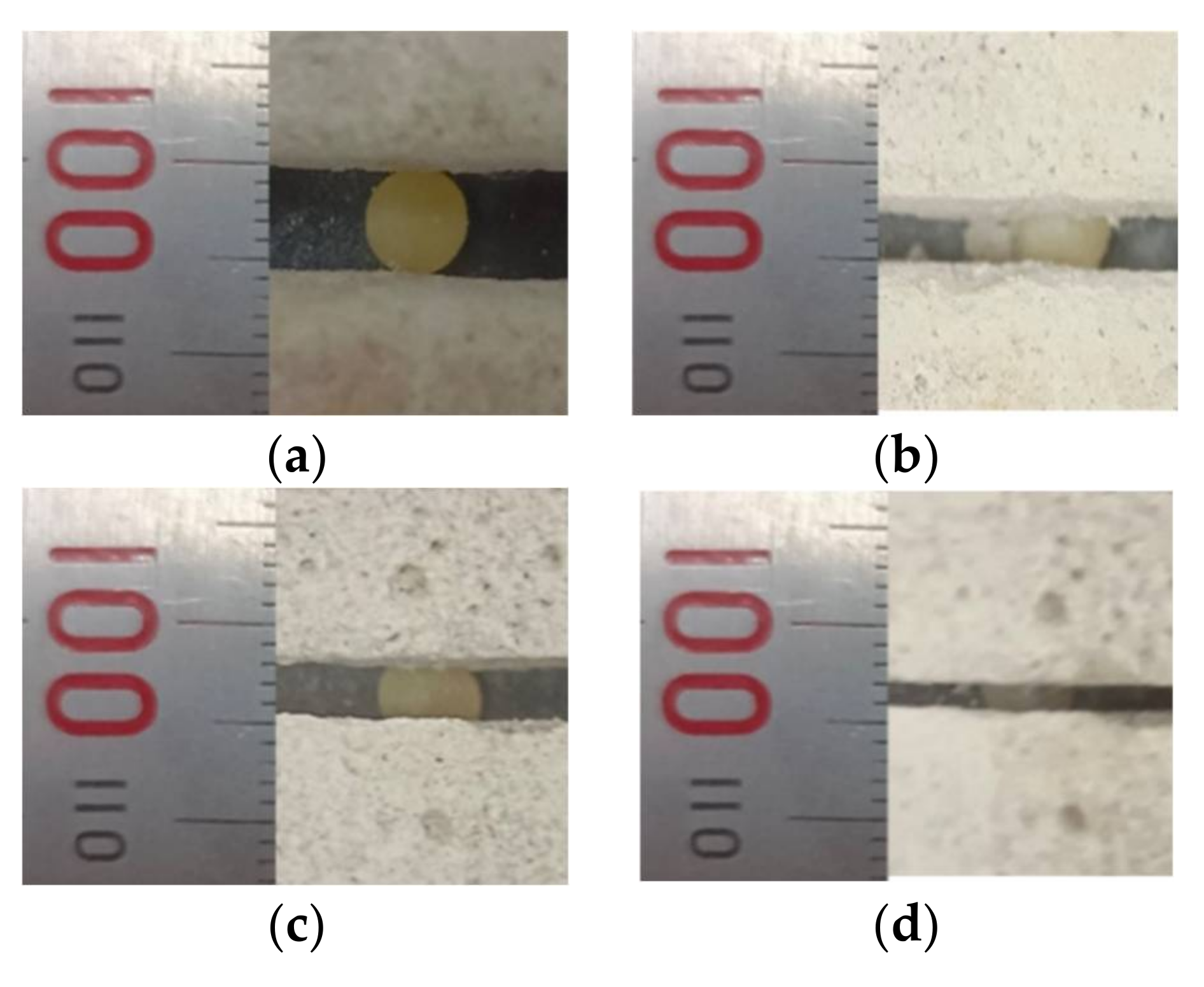
3.2.1. Analysis of Diversion Capacity and Proppant Embedment
- Mix montmorillonite, kaolinite and illite at a mass ratio of 7:2:1 as the clay component;
- Add quartz sand, clay and lime at the mass ratio of 8:1:1;
- Weigh a certain mass of the above-mentioned gravel into a beaker, and add the tetrahydrofuran solution of different masses into the beaker and stir the solution until the mixture is uniform;
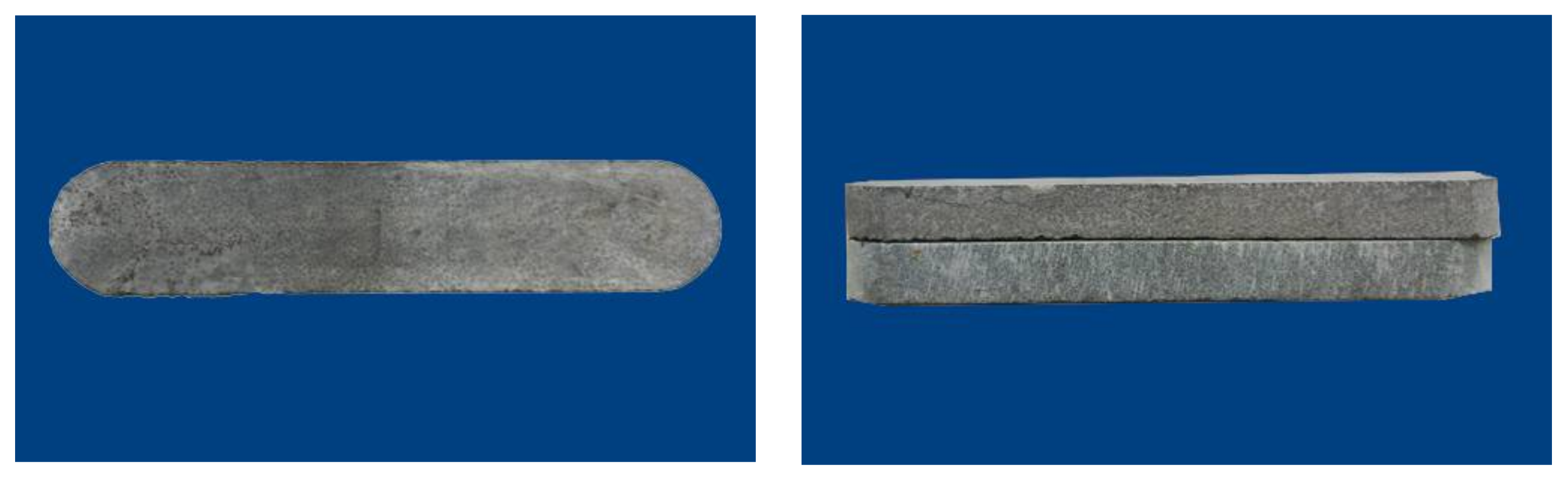
- Add the tetrahydrofuran-containing core sand and gravel into the abrasive tool in layers (Figure 12) and compact them layer by layer with a wooden rod. After filling, seal the abrasive tool to prevent volatilization, and let it stand for 7 days until the cement is cured.
3.2.2. Migration Ability
Experiment
Simulation
4. Results and Discussions
4.1. Physical Property Evaluation Results
4.1.1. Proppant Morphology
4.1.2. Compressive Strength
4.2. Application Performance Evaluation Results
4.2.1. Diversion Capacity and Proppant Embedment Evaluation Results
- a.
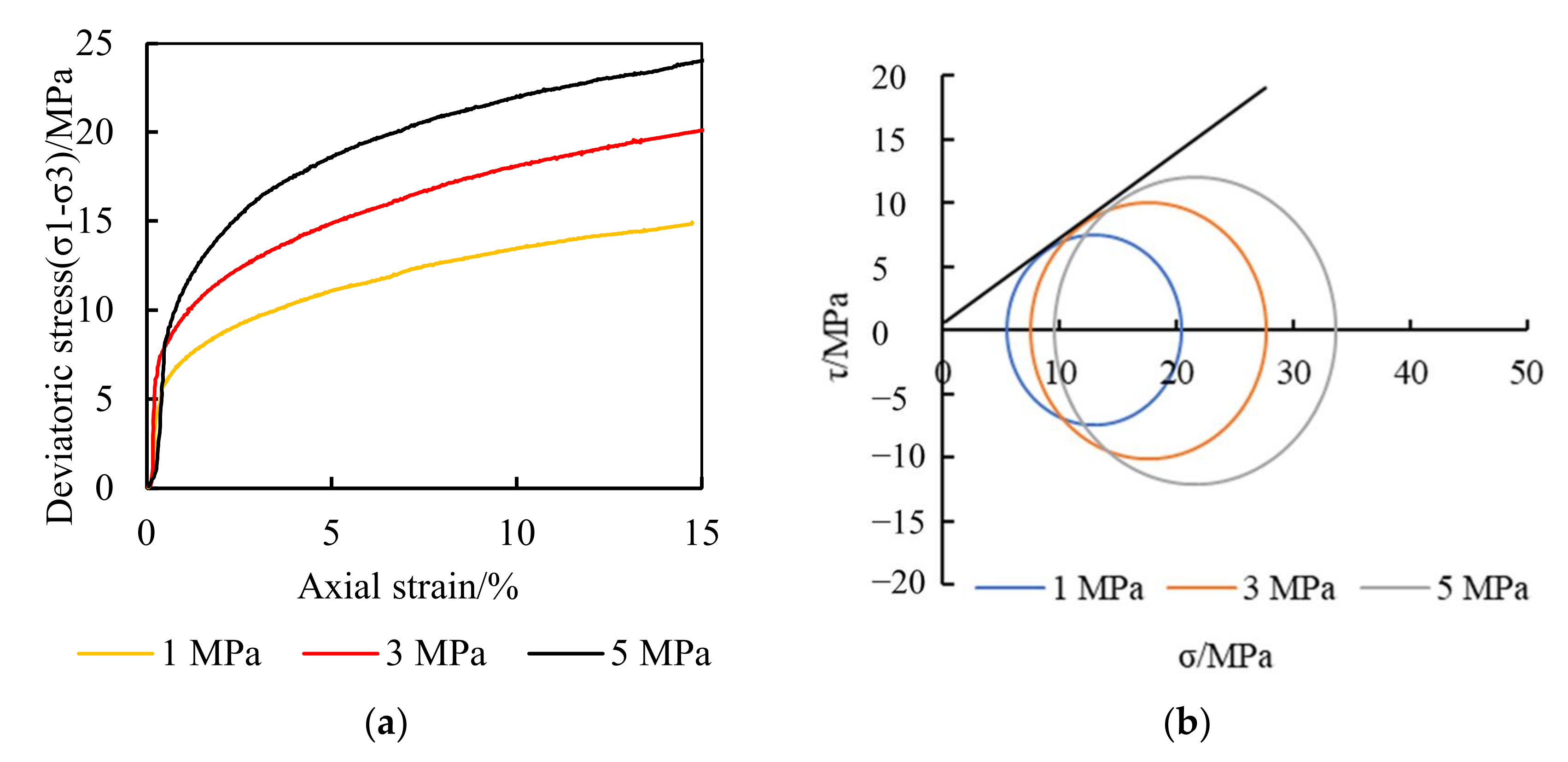
- Mechanical characteristics of the NGH reservoir rock samples
- b.
- Evaluation results of the proppant diversion capacity
- c.
- Analysis results of the influence of proppants embedding in branch cracks and micro cracks
4.2.2. Migration Ability Evaluation Results
Experiment
- a.
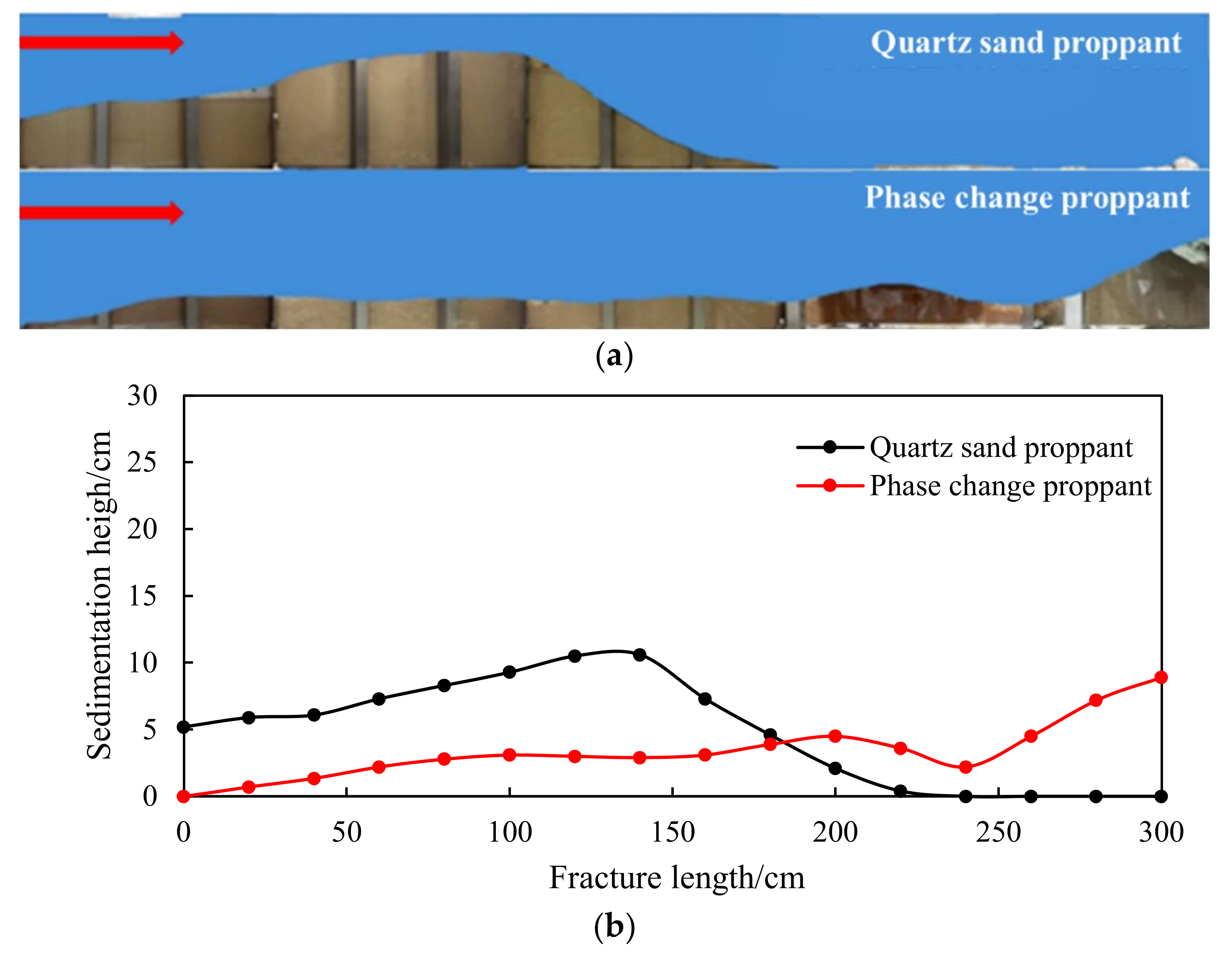
- The migration capacity of the quartz sand and the emulsion large-particle-size phase change proppants is compared, as shown in Figure 22.
- b.
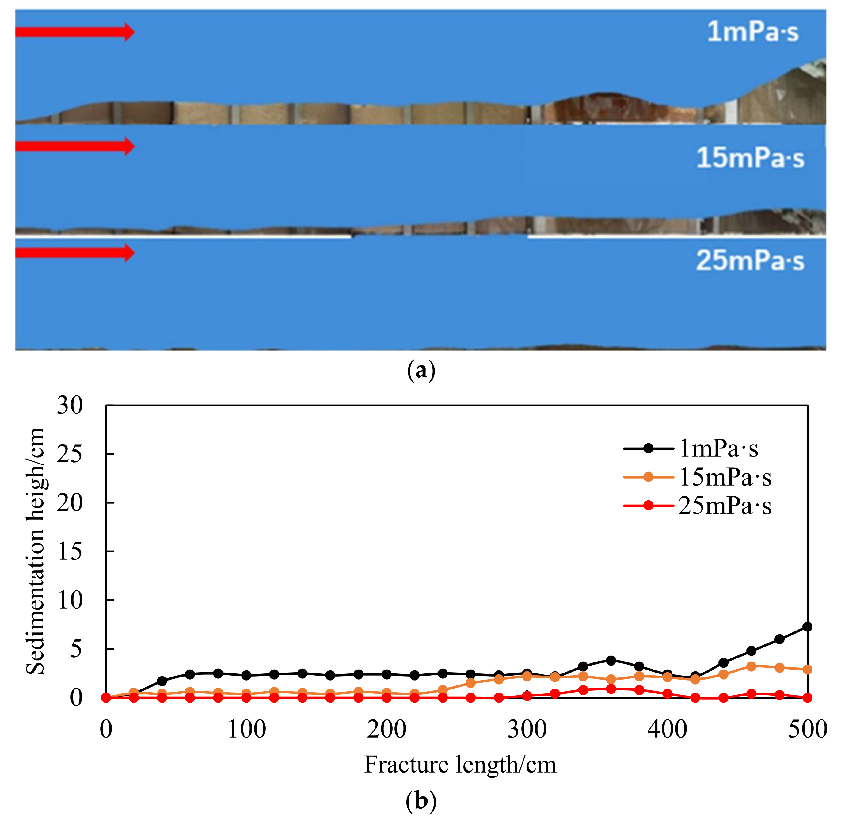
- The comparison results of the migration capacity of the emulsion-phase resin phase change proppant in the carrying fluid with different viscosities are shown in Figure 23.
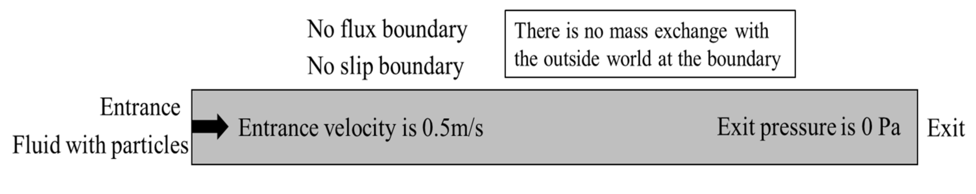
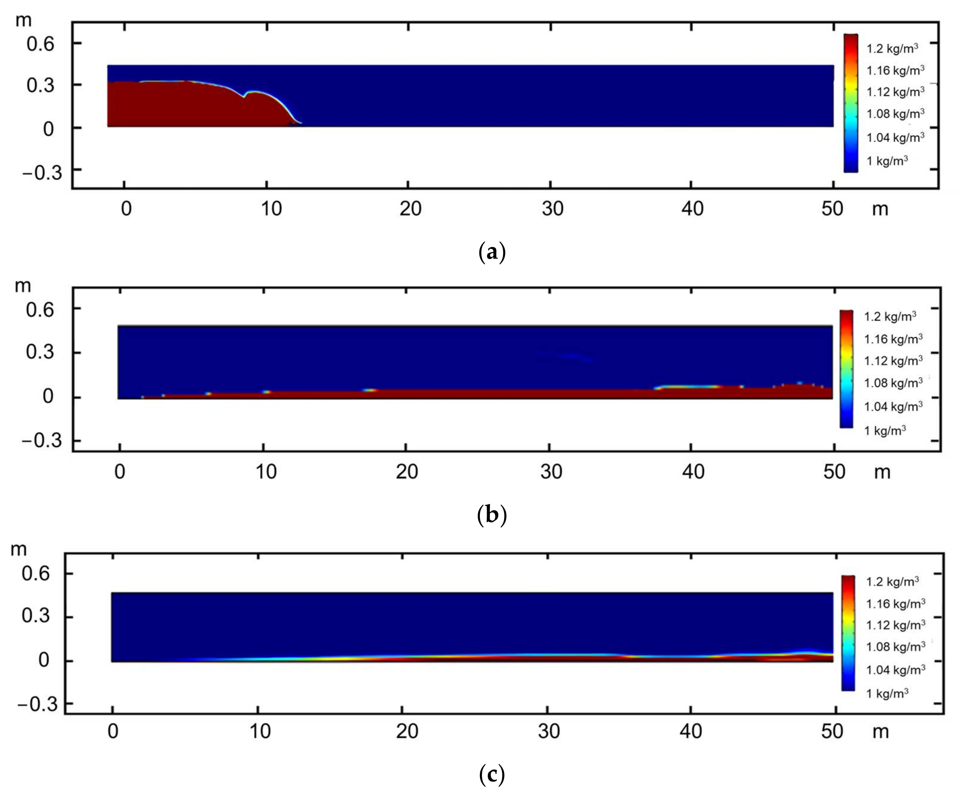
Simulation
5. Conclusions
- Polythiol curing agent was generated by adding the glycerol and mercaptopropionic acid with a molar ratio of 1:3 as the reactive monomer and through esterification with the concentrated sulfuric acid as the acid catalyst and dehydrating agent. The polythiol curing agent is compounded with the amine agent and the adduct of diethylene triamine and butyl glycidyl ether with a ratio of 6:4. The curing time is reduced to less than 40 min under a humid environment at a temperature of 5 °C.
- Large proppants with uniform size can be obtained by adding 0.05 μm SiO2 particles as the emulsifier with the dosage is 0.5% of the resin mass and the ratio of curing system to emulsifier solution as 5:1, with the 20% ethanol as the diluent, and stirring the solution at the rate of 150–200 rpm. The particle size of the obtained proppants is greater than 3 mm. The 100 μm SiO2 particles with the dosage of 0.5% of the resin mass were added for secondary adhesion, which can prevent particle aggregation during the standing of proppants.
- The solidified large-particle-size phase change proppants have more regular morphology than quartz sand and ceramsite, and the compressive strength of the particles decreases with an increase in the size. The compressive strength of 4.5 mm proppants reaches 42 MPa, which meets the needs in the development of NGH reservoirs.
- In the seriously embedded NGH reservoirs, the proppant with particle sizes greater than 3 mm can still maintain good conductivity under the closing pressure of 20 MPa and can also effectively support the branch fracture of the distal fracture. The migration capacity of liquid proppants is much higher than that of solid proppants with the same size, and the migration capacity increases significantly with an increase in the carrying fluid viscosity. The propping position can be controlled accurately by controlling the viscosity of the carrying fluid.
Author Contributions
Funding
Institutional Review Board Statement
Informed Consent Statement
Conflicts of Interest
References
- Liu, X.; Zhang, W.; Qu, Z.; Guo, T.; Sun, Y.; Rabiei, M.; Cao, Q. Feasibility evaluation of hydraulic fracturing in hydrate bearing sediments based on analytic hierarchy process-entropy method. J. Nat. Gas Sci. Eng. 2020, 81, 103434. [Google Scholar] [CrossRef]
- Feng, Y.; Chen, L.; Suzuki, A.; Kogawa, T.; Okajima, J.; Komiya, A.; Maruyama, S. Enhancement of gas production from methane hydrate reservoirs by the combination of hydraulic fracturing and depressurization method. Energy Convers. Manag. 2019, 184, 194–204. [Google Scholar] [CrossRef]
- Shi, S.S.; Chen, X.Z.; Ma, J. Natural Gas Hydrate Reservoir Classification and Characterization in the Well W19 of Shenhu Sea Area, Northern South China Sea. Spec. Oil Gas Reserv. 2019, 26, 24–29. [Google Scholar]
- Draper, E.R.; Adams, D.J. Low-molecular-weight gels: The state of the art. Chem 2017, 3, 390–410. [Google Scholar] [CrossRef] [Green Version]
- Wang, T.Y.; Shen, Z.C.; Liu, M.H. Supramolecular polymer gels. Acta Polym. Sin. 2017, 1, 50–62. [Google Scholar]
- Pei, Y.; Zhao, P.; Zhou, H.; Li, D.; Liao, X.; Shao, L.; Zhang, S.; Tian, F.; Zhao, Y.; Zhang, N.; et al. Development and latest research advances of self-propping fracturing technology. SPE J. 2021, 26, 281–292. [Google Scholar] [CrossRef]
- Kang, B.U.; Jho, J.Y.; Kim, J.; Lee, S.S.; Park, M.; Lim, S.; Choe, C.R. Effect of molecular weight between crosslinks on the fracture behavior of rebber-toughened epoxy adhesives. J. Appl. Polym. Sci. 2001, 79, 38–48. [Google Scholar] [CrossRef]
- Zhao, L.; Chen, Y.; Du, J.; Liu, P.; Li, N.; Luo, Z.; Zhang, C.; Huang, F. Experimental studyon a new type of self-propping fracturing technology. Energy 2019, 183, 249–261. [Google Scholar] [CrossRef]
- Luo, Z.; Zhang, N.; Zhao, L.; Pei, Y.; Liu, P.; Li, N. Thermore-sponsive in situ generated proppant based on liquid–solid transition of a supramolecular self-propping frac fluid. EnergyFuels 2019, 33, 10659–10666. [Google Scholar]
- Chen, L.; Chen, Q.; Xu, L. Preparation and volume stability of polythiol/amine compound modified bisphenol a epoxy resin. Colloids Polym. 2015, 33, 159–161. [Google Scholar] [CrossRef]
- Zhou, S.; Chen, W.; Li, Q. Green mining technology for solid-state sulphurization of deep-water and shallow natural gas hydrates. China Offshore Oil Gas 2014, 26, 1–7. [Google Scholar]
- Zhu, Z.; Yang, J.; Xu, X. Study on reducing viscosity of crude oil emulsions by Pickering emulsion from mineral powder. Mod. Chem. Ind. 2019, 39, 141–145. [Google Scholar]
- Guo, T.; Wang, X.; Li, Z.; Gong, F.; Lin, Q.; Qu, Z.; Lv, W.; Tian, Q.; Xie, Z. Numerical simulation study on fracture propagation of zipper and synchronous fracturing in hydrogen energy development. Int. J. Hydrogen Energy 2018, 44, 5270–5285. [Google Scholar] [CrossRef]
- Ritzenthaler, S.; Court, F.; David, L.; Girard-Reydet, E.; Leibler, L.; Pascault, J.P. ABC triblock copolymers/epoxy-diamine blends. 1. Keys to achieve nanostructured thermosets. Macromolecules 2002, 35, 6245–6254. [Google Scholar] [CrossRef]
- Horozov, T.S.; Binks, B.R.; Gottschalk-Gaudig, T. Effect of electrolyte in silicone oil-in-water emulsions stabilised by fumed silica particles. Phys. Chem. Chem. Phys. 2007, 9, 6398–6404. [Google Scholar] [CrossRef]
- Lee, G.J.; Son, H.A.; Cho, J.W.; Choi, S.K.; Kim, H.T.; Kim, J.W. Stabilization of pickering emulsions by generating complex colloidal layers at liquid-liquid interfaces. J. Colloid Interface Sci. 2014, 413, 100–105. [Google Scholar] [CrossRef] [PubMed]
- Xia, T.; Xue, C.; Wei, Z. Physicochemical characteristics, applications and research trends of edible Pickering emulsions. Trends Food Sci. Technol. 2021, 107, 1–15. [Google Scholar] [CrossRef]
- Wang, Y.Q.; Liu, S.; Liu, Z.P. Water isolation and protective performance of waterborne graphene-dopes epoxy coating. Electroplat. Finish. 2015, 34, 314–319. [Google Scholar]
- Ortiz, D.G.; Pochat-Bohatier, C.; Cambedouzou, J.; Bechelany, M.; Miele, P. Current trends in pickering emulsions: Particle morphology and applications. Engineering 2020, 6, 468–482. [Google Scholar] [CrossRef]
- Miao, C.; Atifi, S.; Hamad, W.Y. Properties and stabilization mechanism of oil-in-water Pickering emulsions stabilized by cellulose filaments. Carbohydr. Polym. 2020, 248, 116775. [Google Scholar] [CrossRef]
- Khedr, A.; Striolo, A. Self-assembly of mono- and poly-dispersed nanoparticles on emulsion droplets: Antagonistic vs. synergistic effects as a function of particle size. Phys. Chem. Chem. Phys. 2020, 22, 22662–22673. [Google Scholar] [CrossRef]
- Liu, X.; Guo, T.; Qu, Z. Feasibility evaluation model and application of hydraulic fracturing in hydrate reservoir. J. Cent. South Univ. 2022, 53, 1058–1068. [Google Scholar]
- Guo, T.; Gong, F.; Lin, X.; Lin, Q.; Wang, X. Experimental investigation on damage mechanism of guar gum fracturing fluid to low-permeability reservoir based on nuclear magnetic resonance. J. Energy Resour. Technol. 2018, 140, 072906. [Google Scholar] [CrossRef]
- Zhu, W.; Liu, Q.; Yue, M.; Zhang, L. Calculation of fracture conductivity considering proppant influence and simulation of proppant transport in fracture. Chem. Eng. Oil Gas 2019, 48, 75–78. [Google Scholar] [CrossRef]
- Koh, D.Y.; Kang, H.; Lee, J.W.; Park, Y.; Kim, S.J.; Lee, J.; Lee, J.Y.; Lee, H. Energy-efficient natural gas hydrate production using gas exchange. Appl. Energy 2016, 162, 114–130. [Google Scholar] [CrossRef]
- Chen, D.; Shi, J.Q.; Durucan, S.; Korre, A. Gas and water relative permeability in different coals: Model match and new insights. Int. J. Coal Geol. 2014, 122, 37–49. [Google Scholar] [CrossRef]
- Liu, X.; Qu, Z.; Guo, T.; Tian, Q.; Lv, W.; Xie, Z.; Chu, C. An innovative technology of directional propagation of hydraulic fracture guided by radial holes in fossil hydrogen energy development. Int. J. Hydrogen Energy 2018, 44, 5286–5302. [Google Scholar] [CrossRef]


| No | Dosage of Polythiol Curing Agent/% | Amine Curing Accelerator Dosage/% | Fully Cure Time/min |
|---|---|---|---|
| 1 | 100 | 0 | 124 |
| 2 | 90 | 10 | 92 |
| 3 | 80 | 20 | 69 |
| 4 | 70 | 30 | 42 |
| 5 | 60 | 40 | 38 |
| 6 | 50 | 50 | 49 |
| 7 | 40 | 60 | 63 |
| 8 | 30 | 70 | 84 |
| 9 | 20 | 80 | 96 |
| 10 | 10 | 90 | 107 |
| 11 | 0 | 100 | 116 |
| Emulsifier Dosage/% | Particle Morphology | Particle Surface Morphology | Surface Coverage/% |
|---|---|---|---|
| 0.15 | No emulsion formed | ||
| 0.25 |  |  | 48% |
| 0.5 | 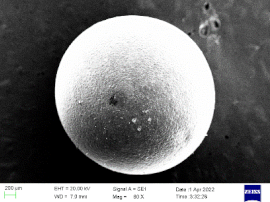 |  | 62% |
| 0.75 | 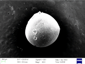 |  | 87% |
| 1 |  |  | 100% |
| Proppant Sizes/mm | Proppant Type | Closing Pressure/MPa | Sand Laying Concentration/kg/m2 |
|---|---|---|---|
| 4.5 | Solidified phase change proppantQuartz sand proppant | 0–20 | 10 |
| 3 | Solidified phase change proppantQuartz sand proppant | 0–20 | 10 |
| 2–2.5 | Solidified phase change proppantQuartz sand proppant | 0–20 | 10 |
| 0.5–1 | Solidified phase change proppantQuartz sand proppant | 0–20 | 10 |
| Proppant Types | Displacement/(m3/h) | Proppant Concentration/% | Frac Fluid Viscosity/mPa·s |
|---|---|---|---|
| Quartz sand proppant | 5.4 | 10 | 1 |
| Emulsion-phase proppant | 5.4 | 10 | 1 |
| Emulsion-phase proppant | 5.4 | 10 | 15 |
| Emulsion-phase proppant | 5.4 | 10 | 25 |
Publisher’s Note: MDPI stays neutral with regard to jurisdictional claims in published maps and institutional affiliations. |
© 2022 by the authors. Licensee MDPI, Basel, Switzerland. This article is an open access article distributed under the terms and conditions of the Creative Commons Attribution (CC BY) license (https://creativecommons.org/licenses/by/4.0/).
Share and Cite
Qu, Z.; Fan, J.; Guo, T.; Liu, X.; Hou, J.; Wang, M. Development and Evaluation of Large-Size Phase Change Proppants for Fracturing of Marine Natural Gas Hydrate Reservoirs. Energies 2022, 15, 8018. https://doi.org/10.3390/en15218018
Qu Z, Fan J, Guo T, Liu X, Hou J, Wang M. Development and Evaluation of Large-Size Phase Change Proppants for Fracturing of Marine Natural Gas Hydrate Reservoirs. Energies. 2022; 15(21):8018. https://doi.org/10.3390/en15218018
Chicago/Turabian StyleQu, Zhanqing, Jiacheng Fan, Tiankui Guo, Xiaoqiang Liu, Jian Hou, and Meijia Wang. 2022. "Development and Evaluation of Large-Size Phase Change Proppants for Fracturing of Marine Natural Gas Hydrate Reservoirs" Energies 15, no. 21: 8018. https://doi.org/10.3390/en15218018