Article

Effect of Compressor-Discharge-Cooler Heat-Exchanger Length Using Condensate Water on the Performance of a Split-Type Air Conditioner Using R32 as Working Fluid

by
Kasni Sumeru
1,
Triaji Pangripto Pramudantoro
1,
Andriyanto Setyawan
1,*,
Rizki Muliawan
1,
Toto Tohir
2 and
Mohamad Firdaus bin Sukri
3
1
Department of Refrigeration & Air Conditioning Engineering, Politeknik Negeri Bandung, Bandung 40559, Indonesia
2
Department of Electrical Engineering, Politeknik Negeri Bandung, Bandung 40559, Indonesia
3
Faculty of Mechanical Engineering, Universiti Teknikal Malaysia Melaka, Melaka 76100, Malaysia
*
Author to whom correspondence should be addressed.
Energies 2022, 15(21), 8024; https://doi.org/10.3390/en15218024
Submission received: 31 August 2022 / Revised: 3 October 2022 / Accepted: 20 October 2022 / Published: 28 October 2022

Abstract

:
The utilization of condensate water as a compressor-discharge cooler results in subcooling on the condenser outlet. On the other hand, a split-type air conditioner (A/C) with R32 as working fluid can provide higher compressor-discharge temperatures than other refrigerants used in the same A/C. Therefore, A/C working with R32, equipped with a heat exchanger by utilizing waste-condensate water as the compressor-discharge cooler, has promising potential to produce the largest subcooling effect in air-conditioning systems. The aim of this study is to investigate the effect of condensate water as the compressor-discharge cooler on the performance of an A/C using R32 as the working fluid with different sizes of heat exchanger. The experimental study was carried out on the A/C with a compressor capacity of 1.1 kW, using three different heat-exchanger lengths, i.e., 18, 20 and 22 cm. The results indicated that longer heat exchangers produced higher degrees of subcooling; the heat exchangers with lengths of 18, 20 and 22 cm produced average degrees of subcooling of 0.9, 1.5 and 4.5 K, respectively. Therefore, increments in the degree of subcooling generate improvements in cooling capacity, lowering the compressor-input power, and enhance the COP of the A/C. The average COP improvement of the A/C with heat-exchanger lengths of 18, 20 and 22 cm were 9.1, 14.4 and 27.3%, respectively.

1. Introduction

Air-conditioning systems consume the highest energy in typical commercial buildings, accounting for more than 50% of the total energy consumption of these buildings [1,2,3]. Therefore, performance improvements in the A/C systems will lead to significant energy saving for buildings. Several methods were developed by previous researchers to improve the performances of the A/C systems used in the building and transport sectors [4,5,6,7,8,9,10]. Qureshi and Tassou [4] investigated the use of variable speed control in A/C; the method can increase COP by up to 15% compared to conventional systems. Kwon et al. [5] reported that the use of VRF on an A/C in office space improved cooling performance by 8.5%. Saidur et al. [6] reported that using nanoparticles in refrigerants reduced power consumption by 9.6%, whereas Sabareesh et al. [7] reported that the nanoparticles in compressor lubricants increased the COP by up to 17%. The increase in COP using the ejector as an expansion device in a refrigeration system was reported by Elbel and Lawrence [8], Bilir and Ersoy [9] and Arsana et al. [10]. They reported that the increases in COP in the system were 7, 22.3 and 39%, respectively.
One of the established methods is the use of a liquid-suction heat exchanger (LSHX) to provide subcooling in the liquid line [11,12,13]. Navarro-Esbri et al. [11] and Pottker and Hrnjak [13,14] experimentally investigated the effects of the use of the LSHX subcooler on a refrigeration system, depending on the refrigerant. In general, this method produced higher cooling capacity and improved the performance of the system. However, previous studies found that these benefits depend on the type of refrigerant being used in the system [15,16,17,18].
Typically, the evaporating temperature of A/C systems is about 5 °C. However, the compressor-discharge temperature depends on the refrigerant being used, usually above 70 °C [19,20]. Due to strong legislative pressure to protect the environment from global warming by reducing greenhouse gases, the environmentally friendly refrigerant, R32, has been applied and commercialized in Asia Pacific countries since 2015. This refrigerant has been successfully used as an alternative to R22, R410A, R404A and R407C. Table 1 shows that, based on the thermodynamic properties, the discharge temperatures of R32 at various isentropic efficiencies are higher than those of R22, R290, R404A and R410A [21]. Therefore, as the condensate water temperature is the same for all A/Cs, the usage of R32 with higher discharge temperatures produces the greatest potential for high heat-transfer rejection rates from the discharge line to condensate water. As a result, it creates the highest subcooling effect on the condenser outlet.
Sumeru et al. [19] investigated the use of condensate water as a discharge cooler on a split-type A/C using R22 as a refrigerant, with a cooling capacity of 2.5 kW. They reported that the experiment resulted in a condenser-outlet temperature reduction of 2.2 °C compared to the baseline system without utilizing condensate water. In other words, utilizing condensate water generated a subcooling of 2.2 K. This subcooling caused an increase in cooling capacity. In addition to improving the cooling capacity, it also reduced the input power by 6.3%. A further investigation by Sumeru et al. [20] showed that the degree of subcooling for this A/C equipped with R32 was recorded at 4.5 K (105% higher than that of A/C with R22). The higher degree of subcooling was due to the higher discharge pressure of the A/C. This subcooling resulted in a cooling-capacity improvement of 13.8%. As with a previous study [19], in addition to gaining improvements in cooling capacity, the use of condensate water also reduced the input power by 10.9%. As a result of the increase in cooling capacity and decrease in input power, the COP of the A/C increased by 21.7% [20].
Other experimental studies using condensate water to enhance the performance of A/C systems were conducted by Delfani et al. [22], Sawant et al. [23], Britto and Vasanthanathan [24], Sawan et al. [25], Tissot et al. [26] and Ibrahim et al. [27]. The difference between these studies and the research conducted by Sumeru et al. [19,20] is in the manner in which the condensate water was utilized. These researchers employed condensate water as a working fluid for an evaporative cooler to decrease the air temperature before entering the condenser coil. Meanwhile, the studies by Sumeru et al. [19,20] used condensate water to reduce the compressor-discharge temperature using the heat exchanger. Delfani et al. [22], Sawant et al. [23], Britto and Vasanthanathan [24] and Ibrahim et al. [27] reported that their studies resulted in input-power reductions of up to 55%, 10%, 8% and 6.1%, respectively. In practical terms, the use of condensate as a compressor-discharge cooler is simpler and more in line with the concept of the closed system (which involves less heat loss and is thus more efficient), than the use of condensate water as the working fluid for an evaporative cooler to lower the air temperature entering the condenser coil.
Current trends show that refrigerant of R32 is widely used as the working fluid in split-type A/C, especially in South-East Asian countries, such as Singapore, Malaysia and Indonesia. This emergence of R32 as a future refrigerant started in 2015, when it replaced the less environmentally refrigerants R22, R410A, R404A and R407C. As shown in Table 2, R32 has lower global-warming potential (GWP) compared to these refrigerants (R22, R410A, R404A and R407C). Apart from having lower GWP, the R32 also has zero ozone depletion potential (ODP). Therefore, the aim of this research is to investigate the performance improvement of a split-type A/C using R32 as working fluid and condensate water as a compressor-discharge cooler. To obtain optimum results, the size of the heat exchanger was varied in lengths of 18, 20 and 22 cm.

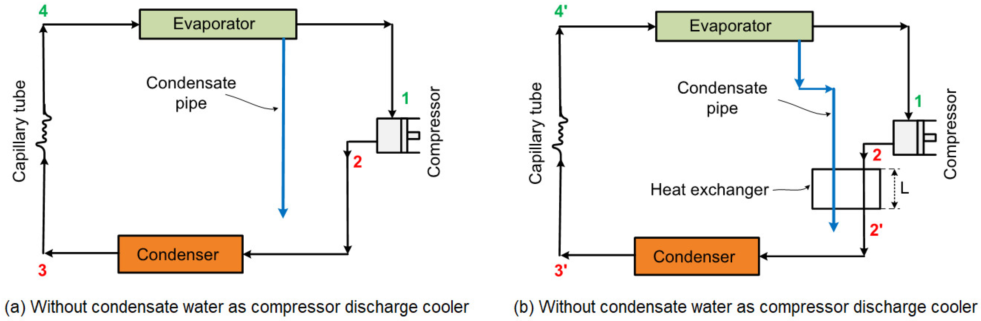
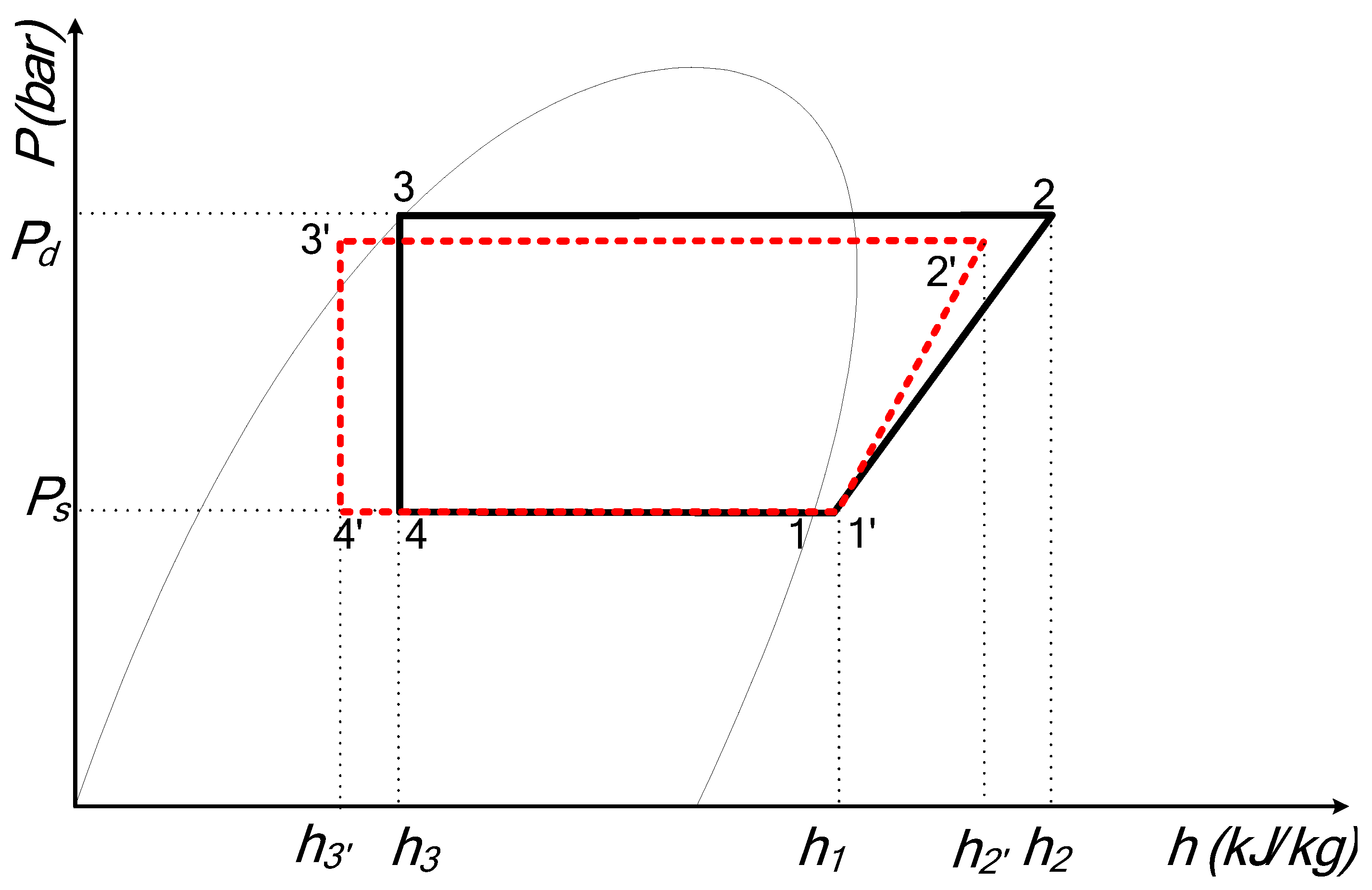
2. System and Configuration

A split-type air A/C has two units, namely indoor and outdoor units. The indoor unit consists of an evaporator, while the outdoor unit consists of a compressor, a condenser and a capillary tube. Generally, for human thermal comfort, the indoor temperature ranges from 20 to 26 °C with a relative humidity (RH) of around 50 to 60%. As a result, the dew-point temperatures of the indoor temperature are about 10–15 °C. Since the evaporator temperature of split-type A/C is about 5–9 °C, water droplets (condensation of water vapor from moist air) will be produced on the evaporator surface. Usually, the condensate water temperature ranges between 12 and 15 °C, above the evaporator temperature. On the other hand, the compressor-discharge temperature is much higher than that of the condensate water. As a result, contact between the condensate water and compressor discharge line/pipe results in subcooling on the condenser outlet. This is because the heat that should be released by the condenser to the ambient air is partially absorbed by the condensate water. The compressor-discharge temperatures of several refrigerants commonly used in split-type A/Cs in South-East Asian countries are illustrated in Table 1. It can be seen from the table that for the same η, the refrigerant R32 has the highest compressor-discharge temperature. As explained earlier, the higher temperature difference between the condensate water and the compressor discharge temperature creates huge potential for producing higher subcooling in the A/C system. In addition to thermodynamic point of view, lower discharge temperature also decreases the input power to the compressor and, therefore, increases the performance of the A/C system.
Schematic diagrams of A/C with and without condensate as compressor-discharge cooler are illustrated in Figure 1a,b, respectively. Figure 1b clearly shows that the condensate water is passed through the compressor-discharge line using a heat exchanger with a length of “L”. This method was applied by Sumeru et al. [19,20]. The refrigerant cycle in the split-type A/C without and with condensate water as a compressor-discharge cooler in Ph (pressure vs enthalpy) diagram is shown in Figure 2. The refrigerant cycle without discharge cooler is illustrated with continues line (process from 1–2–3–4–1). The refrigerant cycle in the A/C with condensate water as a compressor-discharge cooler is represented by dashed line (process 1’–2’–3’–4’–1’). Therefore, based on Figure 2, the cooling capacity, the input power and the COP of the A/C without compressor discharge cooler are calculated using Equations (1)–(3), where:
C C w o = m ˙ ( h 1 h 4 )
P w o = m ˙ ( h 2 h 1 )
C O P w o = C C w o P w o = ( h 1 h 3 ) ( h 2 h 1 )
Next, the cooling capacity, the input power and the COP of the A/C with condensate water as a compressor-discharge cooler are calculated using Equations (4)–(6), where:
C C w i = m ˙ ( h 1 h 4 )
P w i = m ˙ ( h 2 h 1 )
where:
C C w o = cooling capacity without discharge cooler;
C C w i = cooling capacity with discharge cooler;
P w o = input power without discharge cooler;
P w i = input power with discharge cooler;
m ˙ = mass flow rate of refrigerant;
h1 = specific enthalpy at point 1;
h1′ = specific enthalpy at point 1′;
h2 = specific enthalpy at point 2;
h2′ = specific enthalpy at point 2′;
h3 = specific enthalpy at point 3;
h3′ = specific enthalpy at point 3′.
Based on Figure 2, it can be seen that C C w i > C C w o   [ m ˙ ( h 1 h 4 ) > m ˙ ( h 1 h 4 ) ] and P w i < P w o   [ m ˙ ( h 2 h 1 ) < m ˙ ( h 2 h 1 ) ] . Therefore, the increment in cooling capacity and the decrement in input power when using compressor-discharge cooler will generate COP improvement. The cooling-capacity improvement and the input-power reduction of the system after using condensate water as a compressor-discharge cooler or subcooler are calculated using Equations (6) and (7) respectively, where:
C C i m p = ( C C w i C C w o ) C C w o × 100 %
P r e d = ( P w o P w i ) P w o × 100 %
where:
C C i m p = cooling capacity improvement;
P r e d = input power reduction.
In addition, the cooling capacity of the system without or with subcooler can be determined using air-side analysis [10], as in Equation (8):
C C = ρ v A ( h A h B )
where:
ρ = air density;
v = air velocity;
A = cross-sectional area of ducting;
h A = specific enthalpy of the air at the inlet evaporator (mixed air);
h B = specific enthalpy of the air at the outlet evaporator (supply air).
By ignoring small energy losses to the ambient air, with single-phase electrical circuit for the compressor, the power input to the compressor can be calculated as follows:
P = V I P F
where:
P = compressor input power;
V = electrical voltage;
P F = electrical power factor.

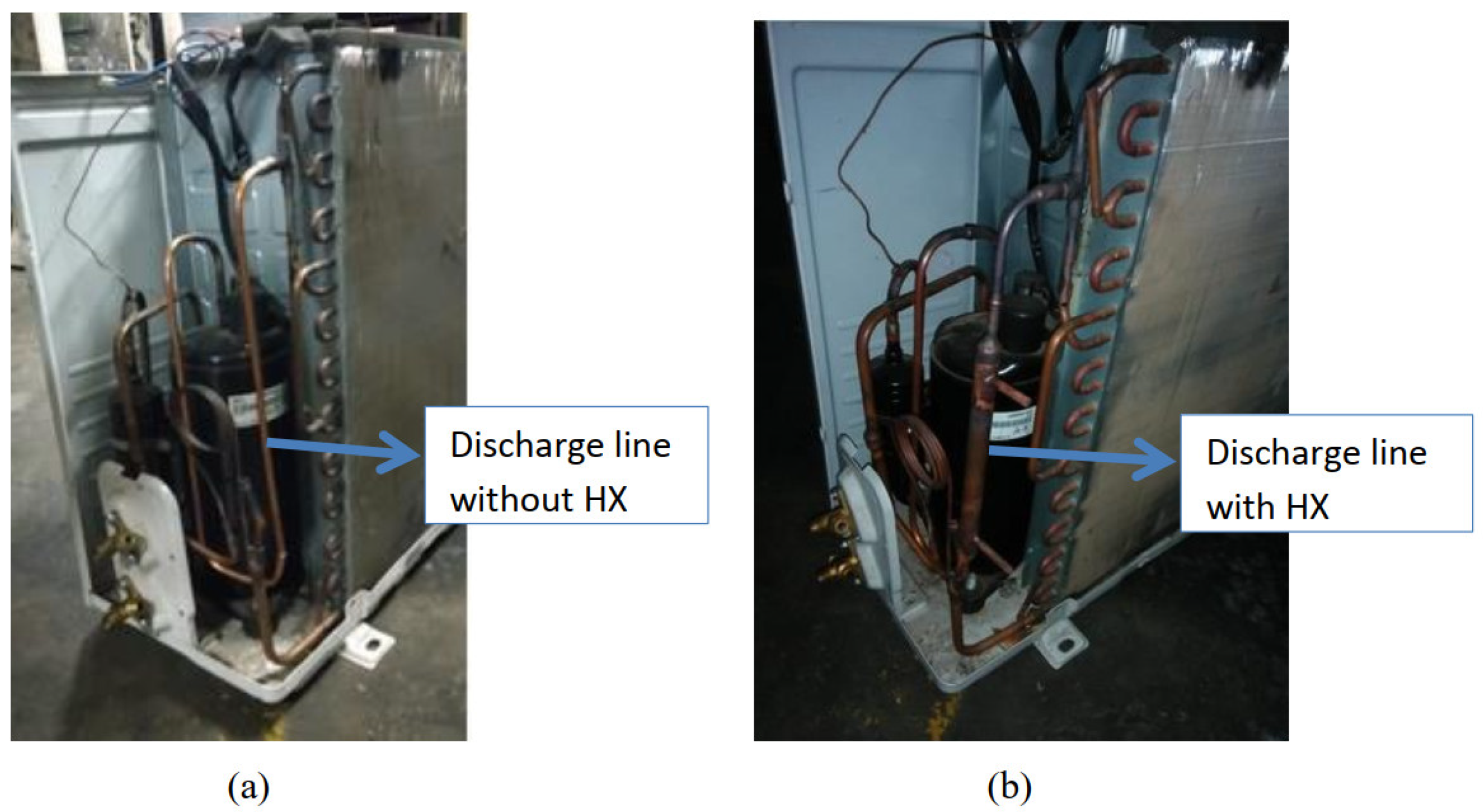
3. Experimental Facility and Method

A split-type A/C with compressor capacity of 1.1 kW with R32 as a working fluid was utilized in this experimental study. Figure 3 depicts the outdoor unit without and with compressor-discharge cooler. The compressor-discharge cooler is a subcooler or heat exchanger (HX) for condensate water to absorb the heat in the compressor-discharge line. The figure shows that type of HX is pipe-to-pipe, and the diameter of discharge pipe is smaller than the HX pipe. The outlet flow of condensate water inside the HX is arranged at the top (facing upward) in order to keep the HX filled with the condensate water. Therefore, parallel-flow HX is used. Experimental study and data measurement were conducted under steady-state conditions (in which condensate water is consistently produced by the A/C). As a result, the condensate water pipeline in the HX was always filled with condensate water. The length of HX was varied at 18, 20 and 22 cm.
Low and high pressurestats were installed in the suction and discharge line of the air conditioner. A pitot-tube manometer was used to measure air flow inside the duct installed in the indoor unit to obtain the cooling capacity of the A/C unit. To measure the input power, an ammeter and voltmeter were utilized.
All experiments were carried out in A/C test chamber which the indoor and outdoor temperatures can be controlled. The experiments were conducted in four stages, i.e.,:
  • Measurement of A/C performance without a heat exchanger standard).
  • Measurement of A/C performance using a heat exchanger with a length of 0.18 m.
  • Measurement of A/C performance using a heat exchanger with a length of 0.20 m.
  • Measurement of A/C performance using a heat exchanger with a length of 0.22 m.
The indoor and outdoor temperatures were controlled constantly at 24 and 34 °C, respectively. Firstly, to ensure steady-state conditions, the experimental test rig was operated 20 min prior to experimental data being recorded. Next, the data measurement was recorded for 180 min with 10-minute time interval for each data measurement. Five parameters were measured, i.e., temperature, pressure, air velocity at the outlet evaporator, electrical current and voltage. The accuracies of each item of measuring equipment are listed in Table 3.

4. Analysis of the Experimental Data

4.1. Effect on the Condenser Outlet Temperature

Figure 4 illustrates the impact of the condensate water as a compressor-discharge cooler on the condenser-outlet temperature, with three different lengths of HX (18, 20, 22 cm), compared to the standard A/C (without HX). It is clearly shown that the temperature of the condenser outlet for the standard system was higher than that of the A/C with condensate water as a subcooler. The average temperature of the condenser outlet for the standard system was 32.3 °C, whereas for the A/C using HX with lengths of 18, 20 and 22 cm, the average temperatures were 31.5, 30.9 and 27.8 °C, respectively. As expected, the use of condensate water as a compressor-discharge cooler led to a decrease in the condenser-outlet temperature. The decrement in temperature of the condenser outlet using HX with lengths of 18 cm and 20 cm was little different. The largest temperature drop in the condenser outlet occurred at the longest HX, of 22 cm. The temperature drop in the condenser outlet resulted in subcooling on the A/C. This led to an increase in cooling capacity. Due to isentropic expansion process, the HX 22 cm in length produced the largest cooling capacity improvement. The quantitative increase in cooling capacity is discussed in the Section 4.2.
The temperature difference of the outlet condenser with and without subcooler is defined as the degree of subcooling on the split-type A/C. The degree of subcooling in the A/C after using three different lengths of HX is shown in Figure 5. The figure depicts that the longer the HX, the higher the degree of subcooling. The highest increase in the degree of subcooling occurred in the HX with a length of 22 cm. The increase in the degree of subcooling from the HX with a length of 18 cm to a length of 20 cm was relatively small compared to the increase from the HX with a length of 20 cm to a length of 22 cm. The increment in the degree of subcooling before 60 min was greater than in the minutes after. The degree of subcooling was stable from 60 to 130 min. After 130 min, the subcooling increased again. The average degrees of subcooling for the HX with lengths 18, 20 and 22 cm were 0.9, 1.5 and 4.5 K, respectively. Compared to the study by Sumeru et al. [19], the decrease in condenser-outlet temperature in this study was slightly smaller. Sumeru et al. [20] also carried out a study on split-type A/C with a compressor capacity of 0.75 kW using HX with a length of 20 cm. They reported a better average degree of subcooling (2.2 K) during 60 min data measurement. This might have been caused by a smaller size of compressor-discharge pipe of A/C with a compressor capacity of 0.75 kW, compared to the compressor-discharge pipe of the A/C with a compressor capacity of 1.1 kW. As a result, the HX in the A/C with a small capacity absorbed more heat than the larger ones.

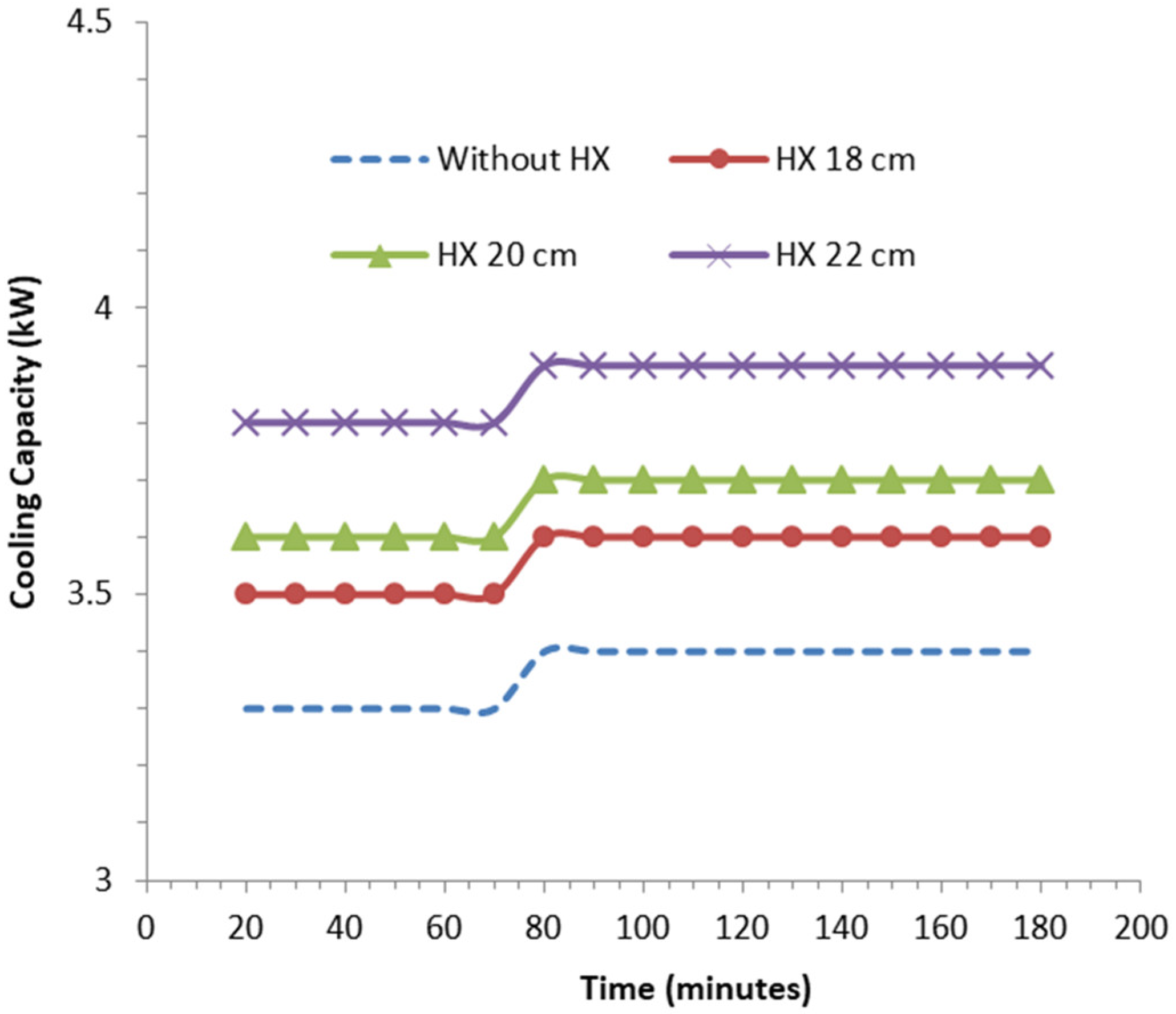
4.2. Effect on the Cooling Capacity

The decrease in condenser-outlet temperature produced a higher degree of subcooling in the A/C. Due to the isentropic expansion process, the increase in the degree of subcooling generated cooling-capacity improvement. Figure 6 shows that the longer the HX, the higher the cooling capacity of the A/C. The average cooling capacity of the A/C without the HX as a subcooler over 180 min was 3.4 kW. Meanwhile, the average of cooling capacities using the HX as a subcooler with lengths of 18, 20 and 22 cm were 3.6, 3.7 and 3.9 kW, respectively. The cooling-capacity increment of the A/C was quite significant for the 22-centimeter-long HX because it had the largest decrement in condenser-outlet temperature, as compared to the A/C equipped with 18- and 20-centimeter long HX. Therefore, it is highly recommended to use the 22-centimeter-long HX for the A/C with a compressor capacity of 1.1 kW.
Using Equation (6), the cooling-capacity improvement in the A/C using the subcooler is depicted in Figure 7. The figure shows that the average cooling-capacity improvements under 180 min operational time for subcoolers with sizes of 18, 20 and 22 cm were 5.9, 8.9 and 14.9%, respectively. Compared to the experimental study conducted by Sumeru et al. [20], the result in this study was slightly higher. Sumeru et al. [20] reported that the cooling-capacity improvement in the A/C with a compressor capacity of 0.75 kW was 13.8%, whereas, in this study, it was recorded at 14.9%. This means that the use of condensate water as the subcooler with a length of 22 cm can be applied to the split-type A/C with capacities of 0.75 and 1.1 kW, and it is expected that cooling-capacity improvements of about 13.8 to 14.9% can be achieved. The high increase in cooling capacity of the A/C with a capacity of 1.1 kW compared to 0.75 kW was due to the fact that the diameter of the A/C discharge line with a capacity of 1.1 kW was greater than 0.75 kW, namely 3/8 inch for 0.75 kW and 1/2 inch for 1.1 kW. The greater the diameter of the discharge line, the greater the absorption of heat by the condensate, causing the cooling capacity to increase. According to these results, it is possible that this condensate could be applied to larger-capacity air conditioners.

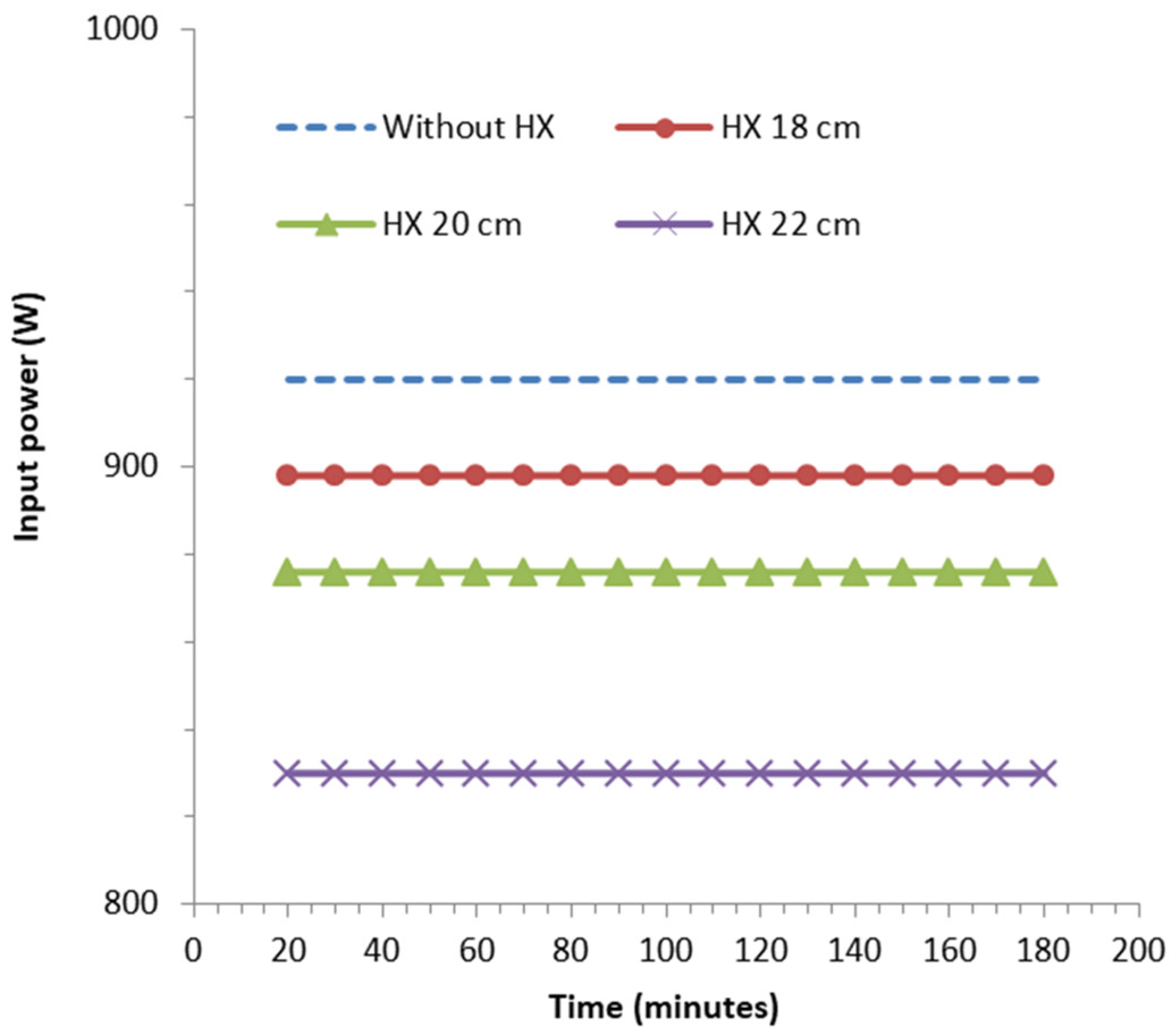
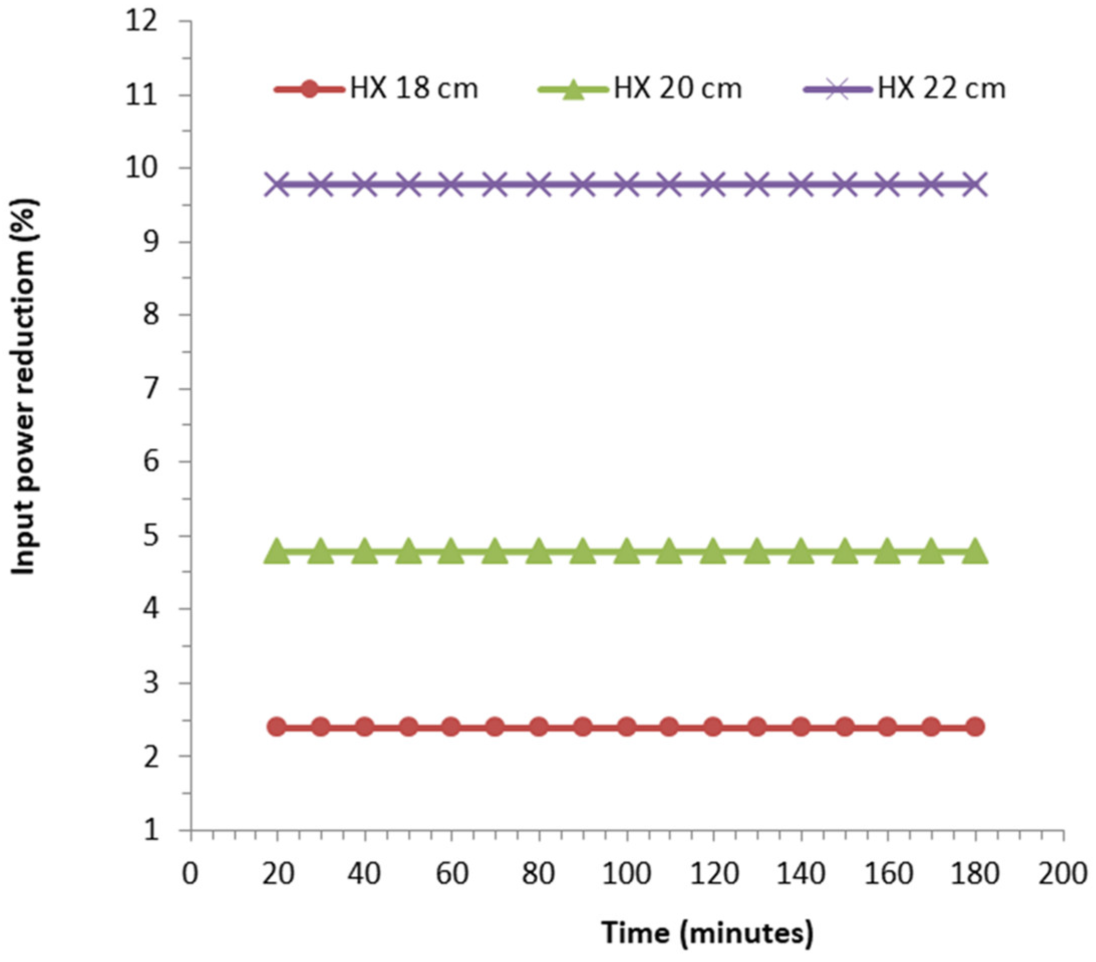
4.3. Effect on the Input Power

The input power is influenced by the pressure ratio between the suction and discharge pressures of the vapor-compression cycle of the A/C. Figure 8 depicts the discharge pressures for four conditions of the A/C without condensate water as a subcooler and with condensate water as a subcooler, at three different lengths of HX. It can be seen that the discharge pressure using the subcooler with three different lengths of HX is always lower than that without the subcooler. The longer the HX, the lower the discharge pressure. Comparing all the different lengths of the HX, the decrement in discharge pressure for the HX with a length of 20 cm was the lowest. Based on Figure 8, the average discharge pressures for the four conditions (with subcooler, with 18, 20 and 22 cm long of HX as a subcooler) were 26.8, 26.1, 25.8 and 25.1 bar, respectively.
Since the suction pressures for all four cases under 180 min of measurement were constant at 10.3 bar, the A/C equipped with the 22-centimeter-long HX as a subcooler results in the lowest pressure ratio. As the discharge pressure changes while the suction pressure remained constant, the pressure ratio became varied for these four cases (Figure 9). Consequently, the pressure ratio decreased as the length of the HX increased. The average pressure ratio of the A/C with the 22-centimeter-long HX installed as a subcooler was the smallest (2.43), followed by the A/C with the 20-centimeter-long HX (2.50), the A/C with the 18-centimeter-long HX (2.53), and the baseline A/C without HX (2.60).
Figure 10 shows the input-power variation for all four cases. It is clearly shown that the largest input power was for the baseline case of the A/C without HX as the subcooler (0.920 kW), followed by the A/C with 18-centimeter-long HX (0.898 kW), the A/C with the 20-centimeter-long HX (0.876 kW) and the A/C with the 22-centimeter-long HX (0.830 kW). A significant input-power reduction was obtained in the A/C with the 22-centimeter-long HX as this case featured a greater pressure-ration reduction compared to the other cases (Figure 9). In short, the pressure ratio is strongly correlated with the input power; a greater pressure ratio indicates that the compressor has to work harder, and vice versa.
The percentage of the input-power reduction due to the use of condensate water as a subcooler was calculated using Equation (7) and is illustrated in Figure 11. The figure shows that as a result of the variation in the pressure ratio and input power described above, the highest input-power reduction compared to the baseline case was 9.8% for the A/C with 22-centimeter-long HX, followed by 4.8% and 2.4% for the A/C with the 20-centimeter- and 18-centimeter-long HX, respectively. The input-power reduction in this study was slightly lower than that reported by Sumeru et al. [20]. It was reported that the input-power reduction on a split-type A/C with a compressor capacity of 0.75 kW, using the same type of refrigerant and 22-centimeter-long HX, was 10.9%. It is likely that the difference in capacity between 0.75 and 1.1 kW led to a higher percentage of input-power reduction for the lower-capacity A/C. As a result of the same size (length) of the HX and lower input power of the baseline case (the case without the subcooler), the HX equipped at a lower capacity of A/C produced a higher percentage of input-power reduction.

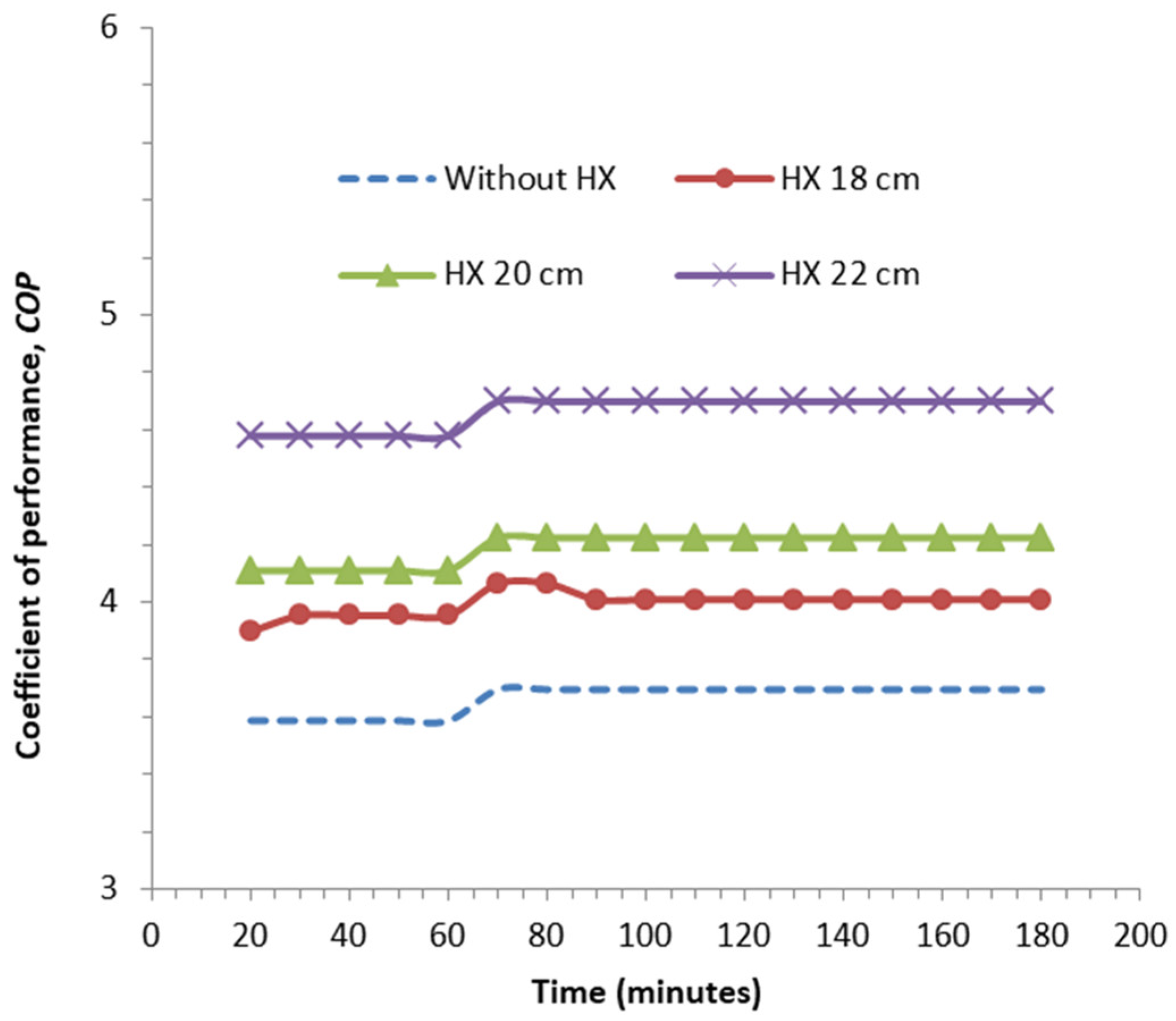
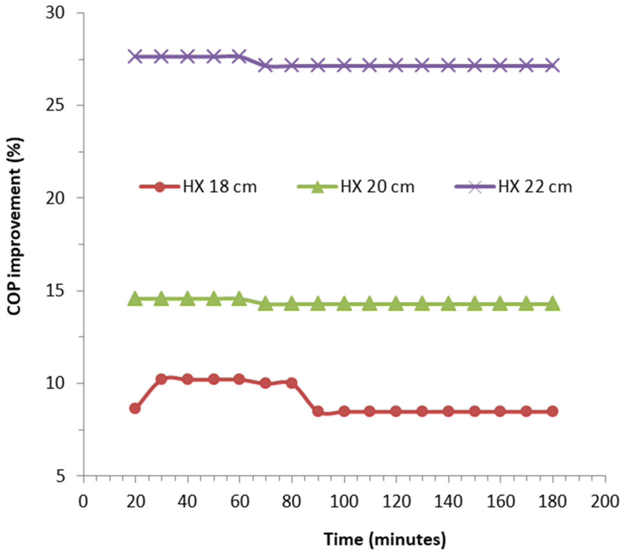
4.4. Effect on the Coefficient of Performance

As expressed in Equation (3), the COP is the ratio between the cooling capacity and the input power. Hence, the increase in cooling capacity and a reduction in input power by using condensate water as a subcooler led to a significant improvement in the COP. Figure 12 depicts the COP of the A/C for four different conditions. The COPs for four different conditions of A/C without HX, and A/C with HX with lengths of 18, 20 and 22 cm, were evaluated at 3.7, 4.0, 4.2 and 4.7, respectively. In this study, it was found that the longer HX works well as a subcooler to absorb heat from the compressor-discharge point and, thus, produces a better subcooling effect, which later leads to significant improvements in cooling capacity and input-power consumption. Therefore, longer HX produces a higher COP than shorter HX.
The concept that explains the COP improvement is similar to the concept of the cooling-capacity improvement. Figure 13 shows the variation in the COP improvements for the A/C equipped with HXs compared to the baseline case of the A/C without HX. In general, the average COP improvements for the A/C with HX 18, 20 and 22 cm in length were recorded at 9.1, 14.4 and 27.3%, respectively. The higher COP improvement, of 27.3%, achieved by the longest HX, was due to the highest cooling-capacity improvement and largest input-power reduction. However, compared to the results reported by Sumeru et al., who reported a COP improvement of 27.7% [20], the COP in this study was slightly lower. However, compared to the COP improvement reported by Ibrahim et al., of 21.4% [27], the COP improvement in the current study was better. In addition to superior energy efficiency, the method used in this study is also simpler and cheaper.

4.5. Regression Analysis

As shown in Figure 14, the required power, cooling capacity and COP of the A/C unit increased as the length of the HX increased. Using linear approximation, the power, cooling capacity and COP increased by 1.85%, 2.25% and 4.55%, respectively, for each cm of increase in the HX length. These correlations are valid for the predetermined range of the HX length from 18 to 22 cm and are presented in Equations (10)–(12).
P i n c = 185   L 31.33
C C i n c = 225   L 35.1
C O P i n c = 455   L 74.067
Here, Pinc, CCinc and COPinc represent the increase in power, cooling capacity and COP as percentages, respectively, while L represents the length of the HX in meters.
In terms of the degree of subcooling, the power increased by 1.91% for each 1 °C increase in the degree of subcooling. Meanwhile, the cooling capacity and the COP increased by 2.32% and 4.77%, respectively, for each 1 °C increase in subcooling. These correlations are expressed in Equations (13)–(15).
P i n c = 1.911   Δ T S C 1.312
C C i n c = 2.316   Δ T S C 4.624
C O P i n c = 4.766   Δ T S C 6.075
where Δ T S C is the degree of subcooling in °C due to the presence of the HX. Again, these correlations are valid only for the range of subcooling from 0.9 °C to 4.5 °C. As a comparison, Xu and Hrnjak [29] reported an increase in COP with subcooling in which the COP consistently increased at low subcooling, reached its maximum value at a subcooling of 6.5 °C and decreased at subcooling levels higher than 6.5 °C. Meanwhile, Pottker and Hrnjak [13] noted a maximum COP improvement when the subcooling reached 11.4 °C for R134a and 12 °C for R1234yf. However, these higher degrees of subcooling were obtained using a longer double-tube internal HX 1.5 m in length.

5. Conclusions

The performance of a split-type A/C using R32 as working fluid, equipped with different lengths of HX as a subcooler were experimentally evaluated. The HX or subcoolers with three different lengths, 18, 20 and 22 cm, were installed between the compressor and the condenser as compressor-discharge coolers. The HX utilized the waste-condensate water as a low-temperature fluid to absorb heat from a high-temperature refrigerant that extended from the compressor-discharge point. As a result, a better effect of subcooling was generated at the outlet condenser than at the A/C without the HX as the compressor-discharge cooler. Based on the experimental results, the following conclusions were drawn:
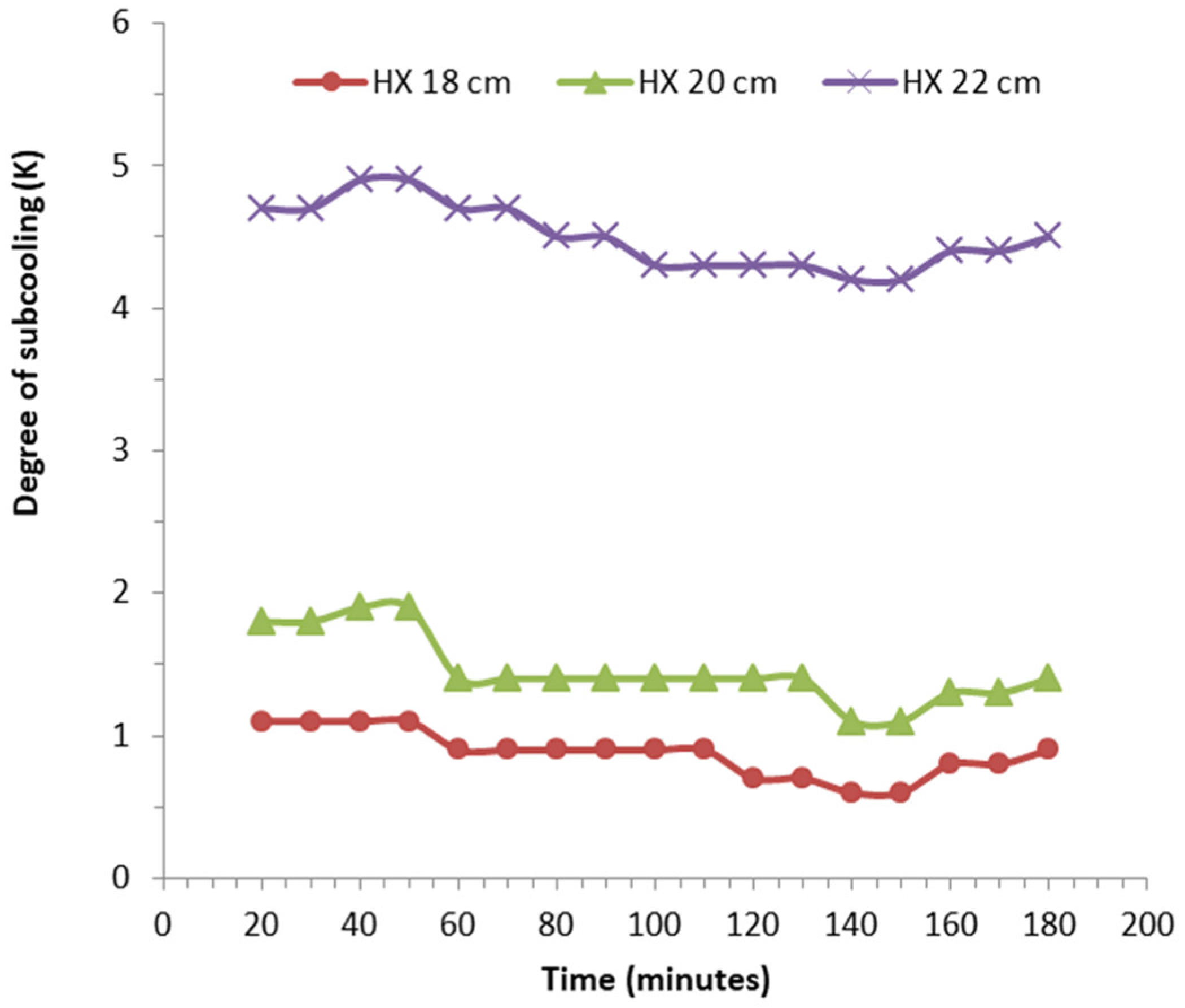
  • By applying HX as the subcooler, the degree of subcooling improved, with average improvements of 0.9, 1.5 and 4.5 K, at lengths of 18, 20 and 22 cm, respectively.
  • The improvement in the degree of subcooling led to an increase in cooling capacity.
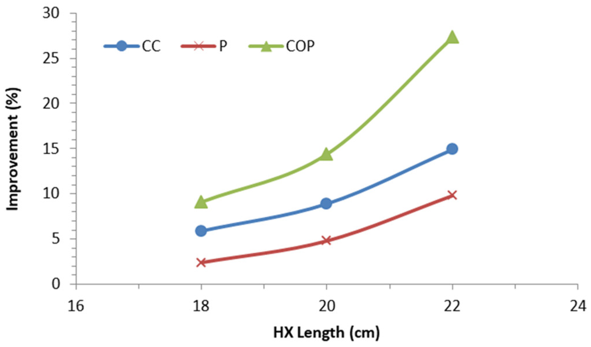
  • Compared to the A/C without a subcooler, average increments in cooling capacity of 5.9, 8.9 and 14.9% and average net-input-power reductions of 2.4, 4.8 and 9.8% were achieved for the A/C with 18-, 20- and 22-centimeter-long HX, respectively.
  • Compared to the method of evaporative cooling proposed by previous researchers, this method is superior in terms of its simplicity, its lack of requirement of additional input power and its ability to produce significant COP improvements of up to 27.3% (on average, for the longest HX, of 22 cm).
To obtain more comprehensive data, this research can be developed in locations that have different climatic conditions so that the effects of using the condensate on each environmental condition can be collected.

Author Contributions

Data curation, T.P.P.; Formal analysis, K.S. and A.S.; Funding acquisition, K.S.; Methodology, A.S., R.M. and M.F.b.S.; Supervision, T.P.P., R.M. and T.T.; Validation, T.T.; Writing—original draft, K.S.; Writing—review & editing, A.S. and M.F.b.S.. All authors have read and agreed to the published version of the manuscript.

Funding

This research and publication were funded by Kemendikbudristek Fund no. 079/SPK/D4/PPK.01.APTV/VI/2022.

Data Availability Statement

This study did not report any data.

Acknowledgments

The authors are grateful to the Department of Refrigeration and Air Conditioning, Politeknik Negeri Bandung, for the facilities and management support.

Conflicts of Interest

The authors declare no conflict of interest.

Abbreviations

Asurface area of the evaporator, m2
A/Cair conditioning
COPcoefficient of performance
C O P ¯ average coefficient of performance
h specific enthalpy, kJ/kg
HXheat exchanger
Ielectrical current, A
Llength of heat-exchanger pipe, m
ηisentropic efficiency, %
Δ T temperature difference, °C
GWPglobal-warming potential
ODPozone-depleting potential
m ˙ refrigerant-mass-flow rate, kg/s
ρair density, kg/m3
Prefrigerant pressure, bar
PFpower factor

References

  1. Llopis, R.; Nebot-Andrés, L.; Sánchez, D.; Catalán-Gil, J.; Cabello, R. Subcooling Methods for CO2 Refrigeration Cycles: A Review. Int. J. Refrig. 2018, 93, 85–107. [Google Scholar] [CrossRef]
  2. Pérez-Lombard, L.; Ortiz, J.; Pout, C. A Review on Buildings Energy Consumption Information. Energy Build. 2008, 40, 394–398. [Google Scholar] [CrossRef]
  3. Sukri, M.; Salim, M.A.; Mohd Rosli, M.A.; Azraai, S.; Dan, R.M. An Analytical Investigation of Overall Thermal Transfer Value on Commercial Building in Malaysia. Int. Rev. Mech. Eng. 2012, 6, 1050–1056. [Google Scholar]
  4. Qureshi, T.Q.; Tassou, S.A. Variable-Speed Capacity Control in Refrigeration Systems. Appl. Therm. Eng. 1996, 16, 103–113. [Google Scholar] [CrossRef]
  5. Kwon, L.; Hwang, Y.; Radermacher, R.; Kim, B. Field Performance Measurements of a VRF System with Sub-Cooler in Educational Offices for the Cooling Season. Energy Build. 2012, 49, 300–305. [Google Scholar] [CrossRef]
  6. Saidur, R.; Kazi, S.N.; Hossain, M.S.; Rahman, M.M.; Mohammed, H.A. A Review on the Performance of Nanoparticles Suspended with Refrigerants and Lubricating Oils in Refrigeration Systems. Renew. Sustain. Energy Rev. 2011, 15, 310–323. [Google Scholar] [CrossRef]
  7. Sabareesh, R.K.; Gobinath, N.; Sajith, V.; Das, S.; Sobhan, C.B. Application of TiO2 Nanoparticles as a Lubricant-Additive for Vapor Compression Refrigeration Systems—An Experimental Investigation. Int. J. Refrig. 2012, 35, 1989–1996. [Google Scholar] [CrossRef]
  8. Elbel, S.; Lawrence, N. Review of Recent Developments in Advanced Ejector Technology. Int. J. Refrig. 2016, 62, 1–18. [Google Scholar] [CrossRef]
  9. Bilir, N.; Ersoy, H.K. Performance Improvement of the Vapour Compression Refrigeration Cycle by a Two-Phase Constant Area Ejector. Int. J. Energy Res. 2009, 33, 469–480. [Google Scholar] [CrossRef]
  10. Arsana, M.E.; Kusuma, I.G.B.W.; Sucipta, M.; Suamir, I.N. Thermodynamic Analysis of Two-Phase Ejector as Expansion Device with Dual Evaporator Temperatures on Split Type Air Conditioning Systems. IOP Conf. Ser. Mater. Sci. Eng. 2019, 494, 12034. [Google Scholar] [CrossRef]
  11. Navarro-Esbrí, J.; Cabello, R.; Torrella, E. Experimental Evaluation of the Internal Heat Exchanger Influence on a Vapour Compression Plant Energy Efficiency Working with R22, R134a and R407C. Energy 2005, 30, 621–636. [Google Scholar] [CrossRef]
  12. Vijayan, R.; Srinivasan, P. Influence of Internal Heat Exchanger on Performance of Window AC Retrofitted with R407C. J. Sci. Ind. Res. 2009, 68, 153–156. [Google Scholar]
  13. Pottker, G.; Hrnjak, P. Experimental Investigation of the Effect of Condenser Subcooling in R134a and R1234yf Air-Conditioning Systems with and without Internal Heat Exchanger. Int. J. Refrig. 2015, 50, 104–113. [Google Scholar] [CrossRef]
  14. Pottker, G.; Hrnjak, P.S. Effect of Condenser Subcooling of the Performance of Vapor Compression Systems: Experimental and Numerical Investigation. In Proceedings of the International Refrigeration and Air Conditioning Conference, Purdue, IN, USA, 16–19 July 2012; p. 1328. [Google Scholar]
  15. Sumeru, K.; Sukri, M.F.; Falahuddin, M.A.; Setyawan, A. A Review on Sub-Cooling in Vapor Compression Refrigeration Cycle for Energy Saving. J. Teknol. 2019, 81, 155–170. [Google Scholar] [CrossRef] [Green Version]
  16. Klein, S.A.; Reindl, D.T.; Brownell, K. Refrigeration System Performance Using Liquid-Suction Heat Exchangers. Int. J. Refrig. 2000, 23, 588–596. [Google Scholar] [CrossRef]
  17. Rodríguez-Muñoz, J.L.; Pérez-García, V.; Belman-Flores, J.M.; Ituna-Yudonago, J.F.; Gallegos-Muñoz, A. Energy and Exergy Performance of the IHX Position in Ejector Expansion Refrigeration Systems. Int. J. Refrig. 2018, 93, 122–131. [Google Scholar] [CrossRef]
  18. Llopis, R.; Nebot-Andrés, L.; Cabello, R.; Sánchez, D.; Catalán-Gil, J. Experimental Evaluation of a CO2 Transcritical Refrigeration Plant with Dedicated Mechanical Subcooling. Int. J. Refrig. 2016, 69, 361–368. [Google Scholar] [CrossRef]
  19. Sumeru, K.; Sunardi, C.; Sukri, M.F. Effect of Compressor Discharge Cooling Using Condensate on Performance of Residential Air Conditioning System. AIP Conf. Proc. 2018, 2001, 020002. [Google Scholar] [CrossRef]
  20. Sumeru, K.; Margana, A.S.; Hidayat, S. Condensate Water as a Compressor Discharge Cooler to Generate Subcooling on the Residential Air Conditioning Using R32 as Refrigerant. J. Phys. Conf. Ser. 2019, 1295, 012044. [Google Scholar] [CrossRef]
  21. Lemmon, E.W.; Bell, I.H.; Huber, M.L.; McLinden, M.O. NIST Standard Reference Database 23: Reference Fluid Thermodynamic and Transport Properties-REFPROP, Version 10.0; National Institute of Standards and Technology: Gaithersburg, MD, USA, 2018.
  22. Delfani, S.; Esmaeelian, J.; Pasdarshahri, H.; Karami, M. Energy Saving Potential of an Indirect Evaporative Cooler as a Pre-Cooling Unit for Mechanical Cooling Systems in Iran. Energy Build. 2010, 42, 2169–2176. [Google Scholar] [CrossRef]
  23. Sawant, A.P.; Agrawal, N.; Nanda, P. Performance Assessment of an Evaporative Cooling-Assisted Window Air Conditioner. Int. J. Low-Carbon Technol. 2012, 7, 128–136. [Google Scholar] [CrossRef] [Green Version]
  24. Britto, J.J.J.; Vasanthanathan, A. Performance Evaluation of Window Air Conditioner by Incorporating Evaporative Cooling System on the Condenser. In Proceedings of the 2013 International Conference on Energy Efficient Technologies for Sustainability, Nagercoil, India, 10–12 April 2013; pp. 796–801. [Google Scholar]
  25. Sawan, R.; Ghali, K.; Al-Hindi, M. Use of Condensate Drain to Pre-Cool the Inlet Air to the Condensers: A Technique to Improve the Performance of Split Air-Conditioning Units. HVACR Res. 2012, 18, 417–431. [Google Scholar] [CrossRef]
  26. Tissot, J.; Boulet, P.; Trinquet, F.; Fournaison, L.; Lejeune, M.; Liaudet, F. Improved Energy Performance of a Refrigerating Machine Using Water Spray Upstream of the Condenser. Int. J. Refrig. 2014, 38, 93–105. [Google Scholar] [CrossRef]
  27. Ibrahim, N.I.; Al-Farayedhi, A.A.; Gandhidasan, P. Experimental Investigation of a Vapor Compression System with Condenser Air Pre-Cooling by Condensate. Appl. Therm. Eng. 2017, 110, 1255–1263. [Google Scholar] [CrossRef]
  28. Zhou, G.; Zhang, Y. Performance of a Split-Type Air Conditioner Matched with Coiled Adiabatic Capillary Tubes Using HCFC22 and HC290. Appl. Energy 2010, 87, 1522–1528. [Google Scholar] [CrossRef]
  29. Xu, L.; Hrnjak, P.S. Potential of Controlling Subcooling in Residential Air Conditioning System. In Proceedings of the International Refrigeration and Air Conditioning Conference, West Lafayette, IN, USA, 14–17 July 2014; p. 1465. [Google Scholar]
Figure 1. Schematic diagrams of the air-conditioning system.
Energies 15 08024 g001
Figure 2. Ph diagram of refrigerant cycle in air-conditioning system with and without condensate as compressor-discharge cooler.
Energies 15 08024 g002
Figure 3. The discharge line of the outdoor unit (a) without heat exchanger as subcooler and (b) with a heat exchanger as a subcooler (length, L = 22 cm).
Energies 15 08024 g003
Figure 4. Temperature of outlet condenser of air conditioner without and with condensate water as a subcooler at three different lengths of heat exchanger.
Energies 15 08024 g004
Figure 5. Degree of subcooling of air conditioner using condensate water as a subcooler for three different lengths of heat exchangers.
Energies 15 08024 g005
Figure 6. Cooling capacities of A/C using condensate water as a subcooler for three different lengths of heat exchangers.
Energies 15 08024 g006
Figure 7. Cooling-capacity improvements of air conditioner using condensate water as a subcooler for three different lengths of heat exchangers.
Energies 15 08024 g007
Figure 8. Discharge pressures of A/C using condensate as a subcooler for three different lengths of heat exchangers.
Energies 15 08024 g008
Figure 9. Pressure ratio of the air conditioner for four different cases.
Energies 15 08024 g009
Figure 10. Variation of input power of the air conditioner for four different cases.
Energies 15 08024 g010
Figure 11. Input-power reduction of the air conditioner using subcooler for three different lengths of heat exchanger.
Energies 15 08024 g011
Figure 12. Coefficient of performance of the air conditioner using subcooler for three different lengths of heat exchanger.
Energies 15 08024 g012
Figure 13. COP improvement of the air conditioner using subcooler for three different lengths of heat exchanger.
Energies 15 08024 g013
Figure 14. Cooling capacity, input power and COP improvements of the air conditioner using subcooler for three different lengths of heat exchanger.
Energies 15 08024 g014
Table 1. The compressor-discharge temperature of air-conditioning system with evaporating and condensing temperatures of 5 °C and 40 °C, respectively [21].
Working FluidThe Compressor Discharge Temperature (°C)
η = 0.50 η = 0.55 η = 0.60 η = 0.65 η = 0.70
R410A80.876.272.669.566.9
R404A60.257.254.752.651.0
R407C73.769.365.562.457.9
R2283.578.474.170.567.7
R3289.884.180.175.270.1
Table 2. The environmental properties of selected refrigerants [28].
Working FluidGWPODP
R410A20880
R404A33000
R2218100.055
R326750
Table 3. The accuracies of measuring-equipment items.
NoEquipmentMeasurementsAccuracyRange
1.K-type thermocoupleTemperature±0.1 °C−50 to 1300 °C
2.Pressure gauge High pressure±0.5 bar−1 to 38 bar
3.Pressure gaugeLow pressure±0.1 bar−1 to 55 bar
4.Pitot-tube anemometerAir velocity±0.05 m/s−15 to 15 in H2O
5.Clamp-on-ammeterElectrical current±0.1 A0 to 600 V
6.VoltmeterElectrical potential±1 V0 to 400 A
Publisher’s Note: MDPI stays neutral with regard to jurisdictional claims in published maps and institutional affiliations.

