Abstract
In this paper, the method and a control algorithm for detecting resonant destruction of a resonant auxiliary power supply for railway vehicle are proposed. It is essential to reduce the weight of the electric equipment attached to the lower part of the railway vehicle because it greatly affects the life of the railway vehicle, such as wheel and bearing. In order to reduce the weight and volume of the auxiliary power supply, in the case of windings, high-speed switching should be performed by lowering the input voltage. Therefore, in this paper, the auxiliary power supply control algorithm using an LLC resonant converter to reduce the weight of auxiliary power supply for railway vehicle is proposed, and the method of detecting resonant destruction due to device failure of a resonant converter is proposed. The proposed algorithm steps down the wire voltage using an input buck converter for high-speed switching, and the inverter input voltage is controlled through the LLC resonant converter. In addition, ZVS (Zero Voltage Switching) is operated to minimize the loss of the resonant converter, and the optimal design of the resonant tank is also proposed. In order to detect resonant destruction, a detection method formulated by analyzing the resonant current peak value for the load capacity is proposed. The algorithm proposed in this paper is verified by simulation and experiment.
1. Introduction
Auxiliary power supply for the railroad vehicle is an essential device because it supplies power to all devices except for the power supply of the propulsion system such as heating and cooling, lighting for rooms, charging batteries, and air compressors used for braking [1,2]. In the case of the conventional auxiliary power supply for railway vehicles, it is composed of a system using a 60 Hz low-frequency transformer at the output of the DC–AC inverter to insulate the input voltage of the temporary line and the three-phase load. An auxiliary power supply device having a system using a low-frequency transformer has a simple structure of the system and easy maintenance, but has a large volume and weight [3]. In addition, since the voltage at the input terminal of the inverter is used as the power line voltage, a large size of each element constituting the inverter is required, and a low switching frequency is needed.
Recently, regulations on carbon emissions have been strengthened around the world, and in Europe and North America, standards for legally regulating greenhouse gas emissions from railroad vehicles have been announced and applied. In Korea, high-efficiency/light-weight research is being actively conducted to improve energy efficiency and reduce carbon emissions of the electronic components of railway vehicles.
The size of the transformer is reduced through an insulated converter using a semiconductor element for high frequency kHz switching operation, instead of the 60 Hz, bulky transformer of the conventional auxiliary power supply for railway vehicles [4,5]. In addition, the resonant converter of the resonant auxiliary power supply operates ZVS to minimize the switching loss, and the optimum values of the resonant reactor (RL) and the resonant capacitor (RC) constituting the resonant tank are proposed. There is a problem in which the resonant frequency increases due to destruction and aging of the resonant reactor and resonant capacitor constituting the resonant tank [6,7]. If the resonant frequency is increased, secondary destruction may occur in the device of the resonant converter due to an increase in the resonant current, so a method for detecting and performing a protective operation is proposed.
In this paper, the auxiliary power supply control algorithm using an LLC resonant converter to reduce the weight of the auxiliary power supply for railway vehicles is proposed.
The proposed algorithm and resonant destruction detection method are verified by the simulation and experimental results.
2. Structure and Design of Resonant Auxiliary Power Supply
Figure 1 shows the conventional auxiliary power supply for railway vehicles. The conventional auxiliary power supply receives the rectified wire voltage 900∼1800 through the rectifier and forms the input voltage of inverter through the LLC filter. The inverter outputs 670 of 3-phase line voltage through voltage control. At this time, a low-frequency transformer of 60 Hz is used for the electrical insulation of the inverter and the output filter, and, finally, 380 line voltage is applied to the load side of the railroad vehicle through the voltage drop of the low-frequency transformer. There is a limit to the increase in the switching frequency of the inverter due to the voltage level at the input stage, and as the weight and size of the low-frequency transformer increases, the overall weight and size of the auxiliary power supply are inevitably increased.
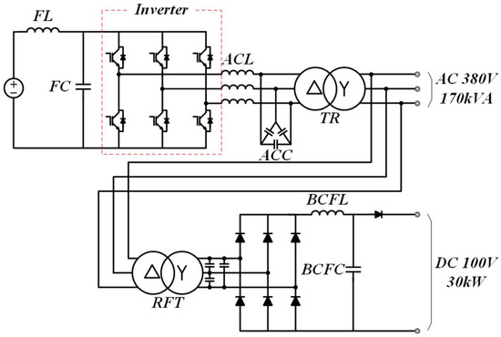
Figure 1.
Conventional auxiliary power supply for railway vehicles.
Figure 2 shows the proposed resonant auxiliary power supply for railway vehicles. The proposed resonant auxiliary power supply is composed of a buck converter, a resonant converter, an inverter, and a battery charger. Part of the buck converter operates to step down the unstable voltage input from the wire, and is designed in a double chopper type configuration to minimize heat generation and reduce device capacity. The resonant converter is a resonant converter part, and the weight and size of the transformer are reduced due to high frequency switching, and it is composed of a resonant capacitor and a resonant reactor. The inverter receives voltage from the resonant converter, outputs 380 between three-phase lines, and delivers the output voltage to the load. The battery charger part is composed of a DC–DC converter. Comparing Figure 1 and Figure 2, the composition and circuit of Figure 2 can be complicated, but due to the difference in weight and size of the windings constituting the main circuit, the proposed resonant auxiliary power supply unit of Figure 2 is a topology suitable for weight reduction. When comparing the weight of the type shown in Figure 1 and the type shown in Figure 2, it can be seen that the weight of Figure 2 is about 20% smaller for the inverter used in the actual electric equipment for railway vehicles (Component abbreviation of the resonant auxiliary power supply shows in Table 1).
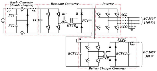
Figure 2.
Structure of the propulsion control system for resonant auxiliary power supply.

Table 1.
Component abbreviation of the resonant auxiliary power supply.
3. Resonant Tank Design of Resonant Auxiliary Power Supply
Figure 3 shows the equivalent circuit of an LLC resonant converter [8]. The resonant tank of the LLC resonant converter consists of a resonant reactor and a resonant capacitor. The selection of the capacity of the elements constituting the resonant tank determines the voltage gain curve and the characteristics of the converter corresponding to the switching frequency. Therefore, the optimal design of the LLC resonant converter resonant tank is essential.
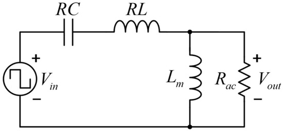
Figure 3.
Equivalent circuit of an LLC resonant converter.
Equation (1) is the voltage gain for the LLC resonant converter, and (2) is the equation for each variable, where K is the voltage gain, is the switching frequency, is the resonant frequency, is the magnetizing inductance, and is the ratio of and . is the resonant inductance, is the resonant capacitance, m is the ratio of and , Q is the quality factor, R is the output resistance, is the equivalent AC resistance on the primary side of R, and and are the number of windings on the primary and secondary sides of the transformer.
Figure 4 shows the voltage gain graph of resonant tank with different m value using the Matlab of Mathworks. Figure 4a shows the gain curve with relatively low m value, and (b) shows the gain curve with high m value. As can be seen in Figure 4, in the high m voltage gain curve, the voltage gain does not change significantly with the change of , and a voltage gain close to 1 is obtained over the entire load. Since the LLC resonant converter of the resonant auxiliary power supply in this paper has a fixed frequency control, it is required to design a high value that is not sensitive to the change of and has a voltage gain approximating 1 in the entire load range. The ratio between the switching frequency and the resonant frequency is an important variable that determines the operating range of the resonant converter. When is higher than 1, the phase of the resonant current operates in an inductive region that is slower than the phase of the resonant voltage. This is advantageous for the ZVS of the primary switch of the transformer because the phase of the resonant current is slow, so a larger resonant current can be secured when the switch is turned on as seen in Figure 5a If it is lower than 1, the phase of the resonant current operates in a capacitive region where the phase of the resonant current is faster than the phase of the resonant voltage. In this area, the resonant frequency is higher than the switching frequency, the secondary side current of the transformer converges to zero within a half cycle of the switching frequency, enabling ZCS operation of the secondary side switch of the transformer as seen in Figure 5b. The resonant converter of this paper has a voltage gain of 1 in the entire load range, and has a high value to enable the ZVS of the primary switch of the transformer and the ZCS of the secondary switch of the transformer, and designed to operate in the capacitive region where f is close to 1. Therefore, in order to design a device having a high value, the capacity of the resonant capacitor was designed as high as possible, and the capacity of the resonant reactor was designed to be the minimum value.
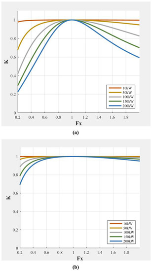
Figure 4.
Voltage gain graph of resonant tank with different m value (a) = 13 F, = 27 H, m = 112 (b) = 48 F, = 7.5 H, m = 400.
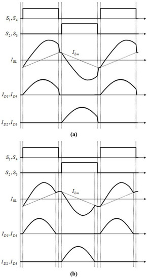
Figure 5.
LLC resonant converter current waveform (a) inductive mode; (b) capacitive mode.
Table 2 shows the LLC resonant converter design parameters. The resonant capacitor capacity was selected as 48 F, which is the maximum value that can operate in the capacitive region that is close to 1 and has a high value in the design with a switching frequency of 7 kHz.
Table 2.
LLC resonant converter design parameters.
4. The Control Algorithm of Resonant Auxiliary Power Supply
Figure 6 shows the control algorithm of the buck converter part of the resonant auxiliary power supply for railway vehicles. As shown in Figure 7, the buck converter is composed of a double chopper in consideration of the temperature rise of the device. The buck converter receives an input line voltage that fluctuates from 900 to 1800 and outputs a stable 722 . In addition, 722 output voltage control is performed by sensing the voltage of the primary side of the transformer, and current control is performed for stabilizing the voltage control. In addition, in order to compensate for the voltage imbalance caused by the voltage difference between the upper and lower phases of the double chopper, the duty ratio considering the voltage difference compensated for the output of the current controller.
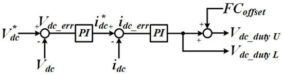
Figure 6.
Control block diagram of buck converter.
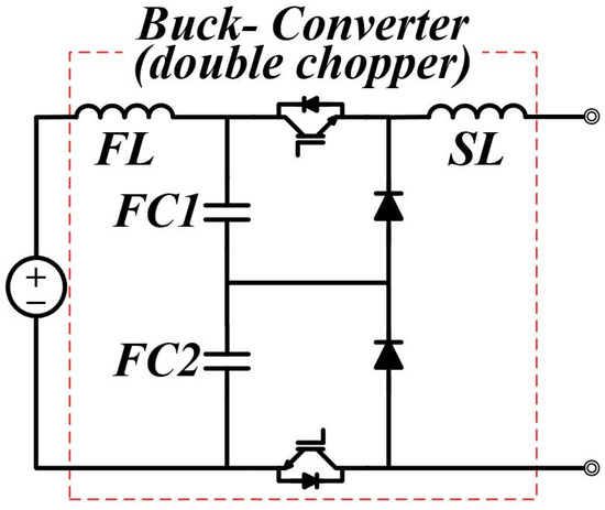
Figure 7.
Part of buck converter.
The resonant converter part (shows in Figure 8) controls the voltage with a switching frequency of 7 kHz and a fixed duty of 0.48. The buck converter output voltage, 722 , is used as the input voltage, and the voltage is transferred to the secondary side of the transformer through high-frequency switching.
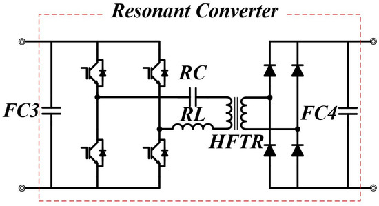
Figure 8.
Part of resonant converter.
At this time, it is stepped down to 670 by the turn ratio of the high frequency transformer to form an input voltage of the inverter input terminal and the converter side of the battery charger.
Figure 9 shows the losses according to the switching method. In the conventional hard switching method, switching loss occurs as much as the area of the overlapping part of voltage and current during on/off. At this time, if the switching frequency is high, a greater loss occurs, the volume of the heat sink increases, and the efficiency decreases.
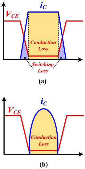
Figure 9.
The losses according to switching method (a) hard switching; (b) soft switching.
The resonant converter performs zero voltage switching (ZVS) using LLC resonant in order to reduce the loss that occurs during high frequency switching. In a resonant converter, since the magnetizing inductance acts in parallel with the load, a wide ZVS area can be realized. When the IGBT of the resonant converter is turned on, ZVS is operated to make the turn-on loss to zero. On the other hand, due to the magnetizing inductance of the high-frequency transformer, the turn-off loss cannot be ignored because switching cannot be performed when the current is 0 A. Therefore, the turn-off loss is minimized by using a transformer with a large magnetizing inductance value from a possible design point. Accordingly, the size of the heat pipe for cooling can be considerably reduced, and the volume of the auxiliary power supply can be reduced by insulating using a high-frequency transformer of the resonant converter.
Figure 10 shows the part of the inverter. Figure 11 shows the control block diagram of inverter. The voltage control and current control are performed in the synchronous coordinate system through conversion by sensing the three-phase output voltage and current. The inverter part receives a stable voltage of 670 and controls to supply the line voltage of 380 and 60 Hz to the load. The power factor is 0.85, and the AC load capacity is designed to be 170 kVA.
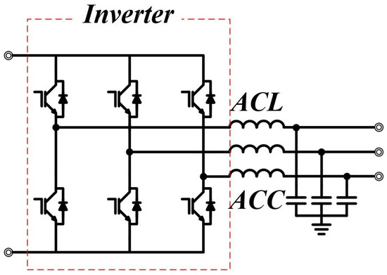
Figure 10.
Part of the inverter.
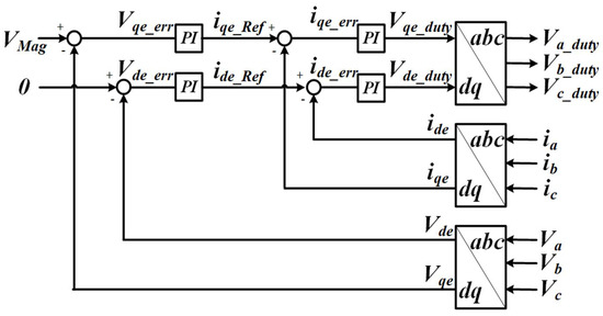
Figure 11.
Control block diagram of the inverter.
Figure 12 shows the part of the battery charger converter. Figure 13 shows the control block diagram of the battery charger converter. The battery charger controls the output voltage by sensing the voltage on the secondary side of the transformer. The error of the battery charger output voltage passes through the PI controller to generate an output current command and outputs the PWM duty of the single-phase full-bridge converter to obtain the output voltage through the internal current controller.
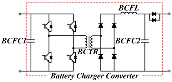
Figure 12.
Part of the battery charger converter.
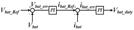
Figure 13.
Control block diagram of the battery charger converter.
The switching frequency of the battery charger part is 6 kHz, and the voltage is transferred to the secondary side through the transformer by complementary switching. The output voltage for charging the battery is controlled by 100 , and the capacity is 30 kW.
Figure 14 shows the control bock diagram of the overall resonant auxiliary power supply system. This is a control block diagram in which each control unit of the resonant type auxiliary power supply described above is combined.
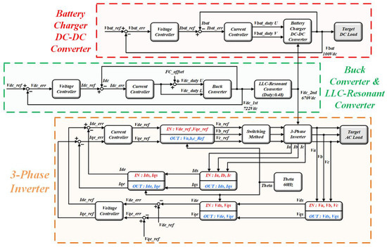
Figure 14.
Control block diagram of the overall resonant auxiliary power supply system.
The buck converter part is stepped down to 722 by receiving the wire voltage, passing through the resonant converter part, forming the inverter and the battery charger input 670 . The inverter part controls voltage to apply line voltage of 380 to the load. In addition, the battery charger unit performs voltage control for 100 output.
5. Resonant Destruction Detection of Resonant Auxiliary Power Supply
The resonant converter part of the resonant auxiliary power supply for railway vehicles has a resonant tank composed of a resonant reactor and a resonant capacitor. The resonant frequency of the resonant converter can be obtained by substituting the parameters of the elements constituting the resonant tank into Equation (1); the problem of increasing the resonant frequency may occur due to destruction of the resonant capacitor or burnout of the resonant reactor. As the resonant frequency increases, the peak value of the resonant current in the same load increases.
If the peak value of the resonant current increases, secondary destruction may occur in the elements constituting the resonant converter, and a temperature rise in the heat pipe and windings may occur. Therefore, it is essential to detect a resonant destruction phenomenon due to an abnormality in the elements constituting the resonant tank and perform a protective operation.
There are two ways to detect an abnormality in the resonant frequency. The first method is to measure the resonant frequency by sensing the point where the actual current on the primary side of the transformer of the resonant converter becomes zero (Zero Crossing Point) and the peak current point (Peak Current Point) in the MCU. An abnormality in the resonant frequency can be detected by comparing the element value of the resonant tank of the resonant converter with the resonant frequency calculated in of Equation (2). This method is suitable for a topology with few MCU-controlled objects because the current sensing period must be much larger than the resonant frequency.
The second method is to detect the resonant frequency abnormality by calculating the ratio of the maximum value of the DC current on the secondary side of the resonant converter transformer and the power at the input side of the resonant converter with the MCU. In this method, as the resonant frequency increases, the magnitude of the resonant current increases, and if the control period and the sensing period are the same and a common multiple, the sensing period may be slow. In the case of a railway system, various operations such as converter and inverter control, sequence control, protection operation control, fault recording, and external communication must be performed within the control cycle. Therefore, if the control period is accelerated, it may cause a problem due to the exceeding of the operation time. Therefore, we propose the second method to detect resonant destruction.
Figure 15 shows the current graph of the secondary side of the transformer at the same load and different resonant frequency. The load is the current area in the graph, and since the load is the same, the area A and the area B in Figure 15 must be the same.
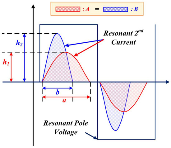
Figure 15.
Control block diagram of the overall resonant auxiliary power supply system.
Equation (3) is an expression for area A, and Equation (4) is an expression for area B. If the area A and the area B are the same, it can be seen that the rate of decrease of the lower side length of the area due to the increase of the resonant frequency and the rate of increase of the current are inversely proportional according to Equation (3):
Figure 16 shows the transformer secondary current peak value corresponding to the load capacity. Equations (6) and (7) represent the equations for each graph in Figure 16. In Figure 16, A shows the normal operation, and B shows the graph at resonant frequency increasing by about 20%. The B has an increased slope than A, and the slope of the graph can be expressed as Equation (7).
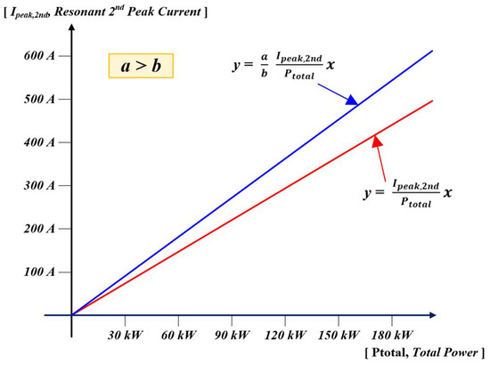
Figure 16.
Transformer secondary current peak value corresponding to the load capacity.
Therefore, in this paper, the fault is detected through the current at the secondary side of the transformer, which increases in case of resonant destruction through Equation (7). A fault is detected when a resonant current that is increased by 20% compared to the normal secondary resonant current of the transformer for the same load capacity is detected. The standard for 20% was selected based on the device specifications of the resonant capacitor constituting the resonant converter.
Figure 17 shows the results of the temperature rise test at 50% load in case of resonant destruction. The fault detection criterion is detected at 30% of the load, but considering the instantaneous peak value and margin factor, it is possible to check the result of whether the device operates normally even at a 50% load in case of resonant destruction.
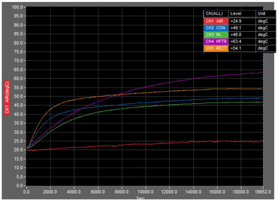
Figure 17.
The results of the temperature rise test at 50% load in case of resonant destruction.
6. Simulation Results
Table 3 shows the specification of resonant auxiliary power supply for railway vehicle, and figure shows the simulation circuit. Figure 18a shows the buck converter part, (b) the resonant converter part, (c) the inverter part, and (d) the battery charger part. As shown in Table 2, the simulation was configured with the same environment as the actual vehicle specifications, and Powersim’s Psim tool was used.
Table 3.
Specification of resonant auxiliary power supply for railway vehicles.
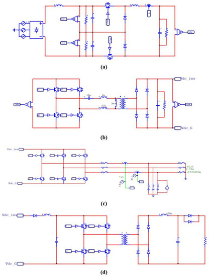
Figure 18.
Simulation circuit.
6.1. Resonant Auxiliary Power Supply Operation Simulation
Figure 19 shows the simulation results of the resonant auxiliary power supply for railway vehicles. Figure 19a shows the operation result at the rated load, and (b) shows the result of the sudden load change test of 0%→50%→100%→50%→0% under load conditions. The proposed resonant auxiliary power supply system is operated, as shown in the simulation result. DC-link voltage is generated by the input buck converter and LLC resonant converter, and the output inverter and battery charger converter operate to generate output voltages of 380 and 100 . In addition, it can be confirmed that the system is capable of normal operation even when the load fluctuates rapidly.
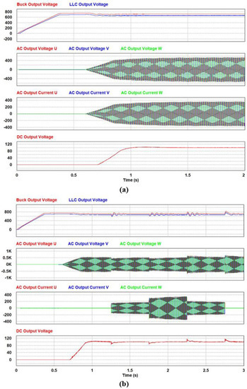
Figure 19.
Simulation results of resonant auxiliary power supply for railway vehicles.
6.2. Resonant Destruction Detection Simulation
Table 4 and Figure 20 show the simulation results of resonant destruction detection. The conditions for simulating resonant destruction were to increase the maximum value of the resonant frequency and resonant current by about 20%; the case when the resonant capacitor was changed from 48 F to 32 F and case 2 when the resonant inductance was changed from 7.5 H to 5 H were selected.
Table 4.
Simulation results of resonant destruction detection.
Figure 20a–c show the voltage and current waveforms of the secondary side of the transformer under the resonant destruction simulation conditions case 1 and case 2, when it is normal at 50% load. As can be seen from the simulation results, the maximum resonant frequency and resonant current in case 1 of the resonant destruction condition are 10.272 kHz and 265 A. Resonant frequency and maximum resonant current in case 2 of resonant destruction condition are 10.235 kHz and 267 A. It can be seen that, when compared with 8.312 kHz and 217 A, which are the results of normal resonant conditions; the average of the frequency increased by 23.36% and the average of the maximum current value increased by 22.58%. That is, it was confirmed by simulation that the maximum value of the resonant current changes as the resonant frequency is different at the same power. Through this result, the validity of the algorithm for detecting resonant destruction with the maximum value of the resonant current was verified.
Figure 20d,e show the simulation results of the operation of the resonant destruction algorithm. The simulation was conducted in case 1 and case 2, which are the simulation conditions for resonant destruction. As shown in the simulation result, it can be confirmed that the protection operation is performed by detecting the maximum resonant current value exceeding 20% compared with the maximum resonant current value of the power calculated when the output voltage increases and exceeds 30% of the rated output. The normal operation and reliability of the proposed resonant destruction detection algorithm were verified through simulation.

Figure 20.
Simulation results of resonant destruction detection.
Figure 20.
Simulation results of resonant destruction detection.

7. Experiment Results
7.1. Experimental Results of the Resonant Auxiliary Power Supply Operation
Figure 21 and Figure 22a show the operation result at the rated load. When the input buck converter operates and outputs 766 , the DC-link voltage of the LLC resonant converter, 670 , the DC-link voltage of the inverter on the secondary side of the transformer, is output. After that, it can be seen that the output inverter and the battery charger converter operate to generate output voltages of 380 and 100 .
Figure 21.
Experimental results of resonant auxiliary power supply for railway vehicles.
Figure 22b is the experimental result of a load sudden change test to verify the suitability of the auxiliary power supply for railway vehicles. There is a verification item that, in case of a sudden change in voltage corresponding to the load, it should converge within 5% of the rated voltage within 0.2 s. In order to verify this item, a load sudden change test of 0%→50%→100%→50%→0% was performed.
Figure 22c,d show the enlarged waveforms at 50%→100% and 100%→50% of sudden load change, respectively. It can be seen that the output voltage of the buck converter, LLC resonant converter, inverter, and battery charger converter performs within a normal range even if the load suddenly changes. The proposed resonant auxiliary power supply system, design method, and control algorithm were verified through experiments.
7.2. Experimental Results of Resonant Destruction Detection
Table 5 and Figure 23 show the experimental results of resonant destruction detection. Resonant destruction conditions were performed by changing the resonant capacitor from 48 F to 32 F to increase the maximum value of the resonant frequency and resonant current by about 20% based on the simulation results.
Table 5.
Experimental results of resonant destruction detection.
Figure 23a,b show the voltage and current waveforms of the secondary side of the resonant converter transformer under normal resonant conditions and resonant destruction conditions at 50% load, respectively. The maximum resonant frequency and resonant current of the normal operation test result in Figure 23a are 8.22 kHz and 204 A, respectively. The maximum resonant frequency and resonant current of the resonant destruction test result in Figure 23b are 9.92 kHz and 246 A. As a result of the test, it can be seen that the resonant frequency and the maximum resonant current increase by 20.68% and 20.58%, respectively, during resonant destruction, compared to the normal resonant conditions. At the same power, it was confirmed that the maximum value of the resonant current changes as the resonant frequency is different, and through this, the validity of the algorithm for detecting resonant destruction with the maximum value of the resonant current was verified.
Figure 23c shows the experimental results of the operation of the resonant destruction algorithm. The experiment was conducted under the conditions of resonant destruction simulation shown in Figure 23b, and the output voltage increases and then a destruction occurs in the part that is more than 30% of the rated output, and the protection operation is performed. It can be confirmed that the protection operation is performed by detecting a large current in which the maximum value of the actual resonant current exceeds 20% comparing the resonant current calculated based on the proposed resonant destruction detection algorithm. Through this experiment, the operation and reliability of the proposed resonant destruction detection algorithm were verified.

Figure 22.
Experimental results of resonant auxiliary power supply for railway vehicles.
Figure 22.
Experimental results of resonant auxiliary power supply for railway vehicles.


Figure 23.
Experimental results of resonant destruction detection.
Figure 23.
Experimental results of resonant destruction detection.

8. Conclusions
In this paper, the method and a control algorithm for detecting resonant destruction of a resonant auxiliary power supply for railway vehicle is proposed. The proposed resonant auxiliary power supply for railway vehicles uses a LLC resonant converter to improve the power density of the system. The power capacity of the proposed resonant auxiliary power supply is AC 170 and DC 30 . The LLC resonant converter of the resonant auxiliary power supply was designed to satisfy robustness to and a voltage gain variation close to 1 over the entire load range, since it performs fixed frequency control. Resonant destruction can be detected by the peak value of the resonant current according to the load capacity compared to the input power. The simulation and experiment were performed to verify the control algorithm and the resonant destruction detection algorithm of the resonant auxiliary power supply for railway vehicles. The conditions for resonant destruction were tested by changing the resonant capacitor so that the maximum values of the resonant frequency and the resonant current could be improved by about 20%.
Author Contributions
Conceptualization, A.-Y.K.; Data curation, A.-Y.K., S.-Y.K. and I.-K.W.; Formal analysis, A.-Y.K.; Methodology, S.-Y.K.; Software, A.-Y.K.; Supervision, A.-Y.K. and S.-Y.K.; Visualization, I.-K.W.; Writing—review & editing, J.Y. and C.-Y.W. All authors have read and agreed to the published version of the manuscript.
Funding
This research received no external funding.
Data Availability Statement
Not applicable.
Conflicts of Interest
The authors declare no conflict of interest.
References
- Zhang, L.; Yun, L.; Sun, M.; Peng, B. Simulation Research on Auxiliary Power Supply System of China Standard EMU. Electronics 2019, 8, 647. [Google Scholar] [CrossRef]
- Diao, L.; Du, H.; Shu, Z.; Xue, Y.; Li, M.; Sharkh, S.M. A Comparative Study Between AI-HM and SPD-HM for Railway Auxiliary Inverter With Pulsating DC Link. IEEE Trans. Ind. Electron. 2018, 65, 5816–5825. [Google Scholar] [CrossRef]
- Diao, L.; Wang, L.; Du, H.; Wang, L.; Liu, Z.; Sharkh, S.M. AI-HM Based Zero Portion Effects and Phase-Shift Optimization for Railway Auxiliary Inverter With Pulsating DC-Link. IEEE Access 2017, 5, 7444–7453. [Google Scholar] [CrossRef]
- Park, H.-P.; Kim, M.; Jung, J.-H. A Comprehensive Overview in Control Algorithms for High Switching-Frequency LLC Resonant Converter. Energies 2020, 13, 4455. [Google Scholar] [CrossRef]
- Youssef, M.; Qahouq, J.A.A.; Orabi, M. Analysis and design of LCC resonant inverter for the tranportation systems applications. In Proceedings of the 2010 Twenty-Fifth Annual IEEE Applied Power Electronics Conference and Exposition (APEC), Palm Springs, CA, USA, 21–25 February 2010; pp. 1778–1784. [Google Scholar] [CrossRef]
- Baek, S.; Kim, H.; Kang, J. Auxiliary Power Unit for Railway Vehicles Using Three-Level LLC Converter with Pulse Width Modulation Control. In Proceedings of the 2019 International Symposium on Electrical and Electronics Engineering (ISEE), Ho Chi Minh, Vietnam, 10–12 October 2019; pp. 232–236. [Google Scholar] [CrossRef]
- He, X.; Chen, Y.; Chen, C.; Zhao, Z.; Han, P. Resonance Parameter of Variable Mode LLC Converter for Auxiliary Converter. In Proceedings of the 2019 10th International Conference on Power Electronics and ECCE Asia (ICPE 2019—ECCE Asia), Busan, Korea, 27–31 May 2019; pp. 1–6. [Google Scholar] [CrossRef]
- Liu, C.-Y.; Liu, Y.-H.; Wang, S.-C.; Yang, Z.-Z.; Ye, S.-P. An Adaptive Synchronous Rectification Driving Strategy for Bidirectional Full-Bridge LLC Resonant Converter. Energies 2021, 14, 2298. [Google Scholar] [CrossRef]


Publisher’s Note: MDPI stays neutral with regard to jurisdictional claims in published maps and institutional affiliations. |
© 2022 by the authors. Licensee MDPI, Basel, Switzerland. This article is an open access article distributed under the terms and conditions of the Creative Commons Attribution (CC BY) license (https://creativecommons.org/licenses/by/4.0/).