Review

Evaluation, Analysis and Diagnosis for HVDC Transmission System Faults via Knowledge Graph under New Energy Systems Construction: A Critical Review

1
CSG EHV Power Transmission Company of China Southern Power Grid Co., Ltd., Guangzhou 510000, China
2
Maintenance and Test Center of CSG EHV Power Transmission Company of China Southern Power Grid Co., Ltd., Guangzhou 510663, China
3
CSG EHV Power Transmission Company of China Southern Power Grid Co., Ltd., Dali Bureau, Dali 671000, China
4
Faculty of Electric Power Engineering, Kunming University of Science and Technology, Kunming 650500, China
*
Author to whom correspondence should be addressed.
Energies 2022, 15(21), 8031; https://doi.org/10.3390/en15218031
Submission received: 7 October 2022 / Revised: 24 October 2022 / Accepted: 26 October 2022 / Published: 28 October 2022

Abstract

:
High voltage direct current (HVDC) transmission systems play a critical role to optimize resource allocation and stabilize power grid operation in the current power grid thanks to their asynchronous networking and large transmission capacity. To ensure the operation reliability of the power grid and reduce the outage time, it is imperative to realize fault diagnosis of HVDC transmission systems in a short time. Based on the prior research on fault diagnosis methods of HVDC systems, this work comprehensively summarizes and analyzes the existing fault diagnosis methods from three different angles: fault type, fault influence, and fault diagnosis. Meanwhile, with the construction of the digital power grid system, the type, quantity, and complexity of power equipment have considerably increased, thus, traditional fault diagnosis methods can basically no longer meet the development needs of the new power system. Artificial intelligence (AI) techniques can effectively simplify solutions’ complexity and enhance self-learning ability, which are ideal tools to solve this problem. Therefore, this work develops a knowledge graph technology-based fault diagnosis framework for HVDC transmission systems to remedy the aforementioned drawbacks, in which the detailed principle and mechanism are introduced, as well as its technical framework for intelligent fault diagnosis decision.

1. Introduction

At present, the world is experiencing energy structure reform to gradually form a new power system based on the large-scale integration of various renewable energies [1,2], in which the digital power grid is the core concept and component. A digital power grid can greatly improve the monitoring performance of the operation characteristics of renewable energy during the energy generation, which is conducive to support thousands of renewable energy technologies as the main energy to become involved in the supervision process of the power system. Thus, the digital grid lays the foundation for the new power system to achieve fully renewable energy absorption, safe and stable operation, and clean and low-carbon operation.
The digital grid is a new operation mode of power systems put forward by China Southern Power Grid Corporation according to the current energy development trend. The digital power grid is the process of digitalization, intelligence, and the internet of the traditional power grid. Digital transformation of the traditional power grid relies on the advanced digital technology platform to connect all links of the power system through the Internet of things and Internet technology. Based on this, grid companies must have super perception ability, wise decision-making ability, and rapid execution ability to promote the reform of energy structures and thus build a safe and reliable digital power grid [3].
At present, photovoltaic and wind power generation schemes are widely concerned by worldwide society, which look to become the main components of the new power system in the future. Meanwhile, since load centers and generation centers are often not in the same area, the generated power needs to be transmitted over long distances to meet the demand in high-load areas. High voltage direct current (HVDC) transmission systems are widely used to deal with the problem of uncoordinated energy distribution due to their large transmission capacity and asynchronous network operation [4,5,6]. Through HVDC transmission technology, renewable energy can be widely connected to the power grid according to local conditions, which improves the flexibility and initiative of the distribution network and promotes the consumption of distributed energy, which currently acts as an indispensable part of the construction of a new power system [7].
Generally, HVDC transmission systems mainly include converter stations, HVDC transmission lines, and the alternating current (AC) part of the converter station. HVDC systems can be classified as unipolar, bipolar, and back-to-back direct current (DC) systems. The failure of any part of the HVDC transmission system will impact the stable operation of the whole transmission system and even cause damage to power equipment [8,9,10]. The inverter side commutation fault is one of the most common faults in HVDC systems. From January to September 2017 alone, AC system failures caused 20 commutation failures in East China [11]. If the reversing fault continues to occur, it may lead to a DC lock, leading to a wide range of power outages, which seriously threatens the security and stable operation of the regional power grid. Therefore, it is very important to study the fault mechanism of the HVDC system and take reasonable and effective measures to ensure the safe and stable operation of the HVDC system for the construction of a digital power grid.
With the increase of DC projects and the continuous expansion of an AC-DC hybrid grid scale, the power grid shows complex characteristics of strong nonlinearity and strong coupling. Under such circumstances, it is necessary to summarize and analyze the possible faults of HVDC transmission systems and related fault analysis and diagnosis methods to ensure reliable operation of HVDC systems under vulnerable conditions. For instance, reference [11] analyzes and summarizes the influencing factors of commutation failure from three aspects: single-channel DC, multi-loop DC, and complex systems. In references [12,13], the evolution mechanism of commutation failures in HVDC transmission systems is analyzed, and the detection and treatment measures of commutation failure are summarized. In reference [14], the mechanism of commutation failure was analyzed from two aspects: device and system. Reference [15] introduces the basic concept of the HVDC transmission system and analyzes the mechanism, types, and hazards of HVDC transmission. In view of the research on fault diagnosis of HVDC lines, references [16,17] discuss the current fault location technologies applied in HVDC transmission lines in detail, including the traveling wave location method, natural frequency method, fault analysis method, and imprecise synchronous location method. In addition, reference [18] reviews the fault location technology of HVDC transmission systems from different perspectives. However, few articles summarize and analyze the specific types of faults of HVDC transmission systems in detail, as well as the research results of the application of artificial intelligence (AI) technology in the fault diagnosis of HVDC transmission systems.
Currently, some of the research on HVDC fault diagnosis is based on the DC transmission fault mechanism model. Reference [19] analyzes the fault mechanism of the system, then determines the fault current and threshold value through the fault equivalent circuit, and lastly classifies the single pole short circuit/double pole short circuit and single pole disconnection fault. In reference [20], the researcher has established a fault equivalent circuit and used the method of analyzing line inductance to locate the fault of the multi-terminal DC line. The aforementioned research mainly uses the method of fault mechanism model analysis to carry out mathematical derivation, obtain the expression of fault current or voltage, and finally make a fault diagnosis. However, when constructing the fault mechanism model to simplify the line expression, some system parameters are inevitably discarded. Meanwhile, the method is affected by parameter changes, load changes, and harmonic waves, which ultimately leads to the reduction of the accuracy of fault diagnosis. Thus, some researchers put forward the method of fault diagnosis based on line signal processing, which does not simplify the circuit model. Reference [21] applies the Fourier transform method to decompose the high-frequency signal of the current waveform and classifies and locates faults through spectrum analysis. References [22,23] use wavelet transform to diagnose HVDC system faults. However, the signal analysis method still needs manual determination of the fault threshold, leading to reduced accuracy. In addition, with the advancement and exploitation of AI technology, AI technology has also been extensively applied in the field of HVDC system fault diagnosis. The basic characteristics of the three types of fault diagnosis methods are demonstrated in Table 1. However, the research of AI technology in the field of power system fault diagnosis started late due to the particularity and secrecy of the power system. Meanwhile, there is no prior article to summarize and analyze the research achievements of the application of AI technology in the field of HVDC transmission system fault diagnosis.
The increasing complexity, intelligence, and large-scale integration of power system equipment mean that traditional fault diagnosis methods can basically no longer meet the development needs of the new power system. AI techniques can effectively simplify solutions’ complexity and enhance self-learning ability, which are ideal tools to solve this problem. As a key branch of AI, the knowledge graph has attracted research interests in recent years with the great progress of 5G technology, big data, and the Internet of Things. Knowledge graph technology is actually an intelligent database that incorporates AI techniques and traditional databases for large-scale knowledge-structured management [24,25]. In 2012, the probability of knowledge graphs was presented by Google for the first time. The core elements such as entities, attributes, and relations are formally described by triples, and the large-scale network information is effectively combined with the minimum cost, to better concatenate and present knowledge [26]. Currently, the research of knowledge graph technology in power systems is in its start-up phase, and the relevant literature mainly focuses on application exploration and macro framework design. In view of the research status of AI technology in the field of HVDC transmission system fault diagnosis, there has been no such state-of-art article to systematically summarize and discuss the research outcomes in detail in recent years. Therefore, this work aims to comprehensively summarize the current research status of AI technology-based HVDC transmission system fault diagnosis. The main contributions and innovations of this work are outlined as follows:
  • A variety of fault types and corresponding adverse effects of HVDC transmission system are summarized in detail;
  • Prior fault diagnosis strategies for HVDC transmission systems in recent years are systematically reviewed. Meanwhile, this work particularly focuses on the application of AI technology in fault diagnosis of HVDC transmission systems;
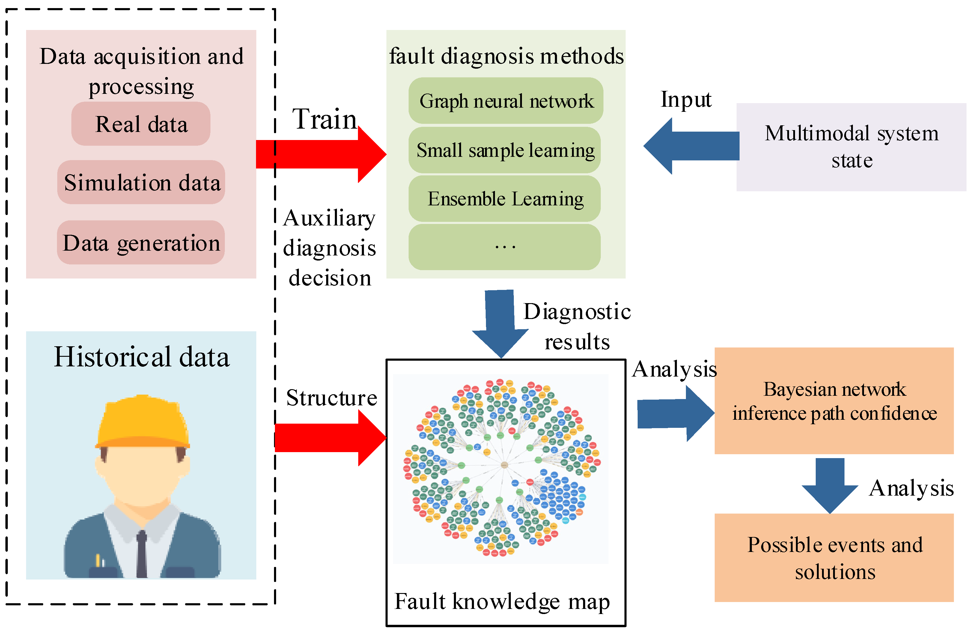
  • The knowledge graph technology is introduced in detail, along with its application in power systems. Inspiringly, a new fault diagnosis framework for HVDC transmission systems based on knowledge graph technology is proposed;
  • According to the current technical foundation and research direction of AI technology, the application of AI technology in HVDC transmission systems is prospected;
  • The main purpose of this work is to provide a one-stop manual for future researchers who may be involved in this field of research.
The overall structure of the work is as follows. In Section 2, the development status of HVDC transmission systems is briefly introduced, and the fault types and fault impact areas of HVDC transmission system are summarized. Section 3 summarizes the current research achievement of HVDC fault diagnosis technology in recent years with the focus on the application of AI technology. In Section 4, the knowledge graph technology is introduced in detail. Section 5 gives a brief discussion and a new fault diagnosis framework for HVDC transmission systems based on knowledge graph technology is proposed. Section 6 concludes the whole work and gives some promising perspectives.

2. Fault Types and Effects of HVDC Transmission Systems

2.1. Development of HVDC Transmission Technology

High voltage direct current (HVDC) transmission technology has been widely used in the world as a powerful complement to AC transmission because of its outstanding strengths in long-distance transmission, high-capacity transmission, asynchronous networking, and submarine cable transmission. According to the different stages of commutator development, the development of DC transmission technology can be divided into three stages: mercury arc valve, thyristor commutator, and voltage source commutator. The mercury arc valve was successfully developed in 1928. Relying on its features of rectifying and inverting, large-capacity DC power transmission was successfully realized. In 1954, the first 20 MW, 100 kV DC single-wire submarine cable was used for power transmission. However, mercury arc valves are complicated, have low reliability, and are difficult to maintain, so they have not been widely used [27].
Since the 1970s, HVDC transmission technology based on phased thyristors has become the main method of large-scale and long-distance power transmission. Compared with mercury arc valves, thyristors have a smaller volume, lower cost, and no reverse arc fault. They are simpler and more convenient to manufacture and maintain than mercury arc valves. Nowadays, most HVDC transmission systems are constructed with commutators. The commutator is intended to transfer the current flowing through the commutator from one current path to another by opening and closing the commutator valve. Line-commutated Converter HVDC (LCC HVDC) is not only the most mature HVDC transmission technology at present but also the mode mainly used in UHVDC transmission. The main converter device of LCC HVDC is the thyristor. LCC HVDC systems are mainly composed of a rectifying station, DC transmission lines, and inverter stations, where the converter, converter transformers, flat wave reactors, reactive power compensation devices, filters, DC grounding, and AC-DC switching equipment are located in the converter stations on both sides [28]. However, the operation of the LCC HVDC system requires the AC system to provide commutation support, which is limited by the system ratio [29].
In the 1990s, with the application of insulated gate bipolar transistors as converters and voltage source converters in power systems, voltage source converter-based HVDC (VSC-HVDC) technology was developed and promoted. Compared with the LCC-HVDC system, the VSC-HVDC system does not depend on the AC system and can control the active and reactive power independently and quickly. LCC-HVDC as the third generation of DC transmission technology combines a procession of power electronics, power systems, automatic control, and so on. It combines various advantages of advanced technology, which has good controllability and adaptability, a flexible operation mode, and applicable range. It plays a significant role in large-scale renewable energy integration in new power systems and digital power grid construction [30].

2.2. Fault Types of HVDC Transmission Systems

According to the different faulty devices, HVDC transmission system faults can be classified into DC faults and AC faults. DC faults [31] include converter faults, DC line faults, ground pole faults, etc. The converter is the core component of HVDC transmission systems, which controllability and single conduction characteristics constitute the important characteristics of faulty behavior of HVDC transmission systems. Generally, converter faults include control system faults and main circuit faults. The main circuit faults mainly include reversing faults and short circuits inside the converter station. Control system fault mainly refers to the valve being closed and opened by mistake [32]. The main failure points of a typical HVDC transmission system are shown in Figure 1 and Table 2.
The most serious fault of the converter is the short circuit fault; the short circuit will make the valve lose shut-off ability or the external insulation between the two ends of the valve is destroyed. When the reverse voltage peak has a large jump, the reversing valve is likely to reverse arc, resulting in a short circuit of the valve arm. In addition, when the lightning arrester short circuits or valve insulation is damaged due to cooling system leakage and gasification, this may also cause a short circuit of the valve [33]. In addition, the inverter valve arm during the blocking period is mostly under the forward voltage; if the voltage is too high or voltage rise rate is too fast, it will affect the insulation of the valve arm and make it damaged, and valve insulation damage after the valve arm will cause a short circuit.
The commutation failure is a failure to complete the commutation before the commutation voltage reverses. Commutation failures are common in inverters and occur during disturbances such as large tributary currents or low AC voltages. At present, the commutation process is mainly analyzed by the commutation voltage integral area theory, as shown in Equation (1) [34].
S demand = L c I d t 2 max + L c I d t 1 t 1 t 2 max U c U b d t = S max
where L c represents commutative reactance. t 1 and t 2 max are the trigger time and the time when the integral area of the commutation voltage is maximum. I d t 1 and I d t 2 max are the current values at t 1 and t 2 max , respectively. S demand is the integral demand area of commutation voltage, and S max is the maximum commutation voltage integral area. Commutation is successful only if inequality (1) is satisfied.
The DC outlet short circuit of the converter is also a common fault, which is a short circuit fault between DC terminals on the converter. The main distinction between the short circuit at the DC side of the rectifier and the short circuit at the valve end is that the valve end of the converter can maintain single-lead connectivity after the short circuit occurs at the outlet of the DC side. After the short circuit at the outlet of the DC side of the rectifier, the current on the conduction valve and converter transformer increases sharply, and it needs to withstand a much higher current value than normal. In addition, the fault point of the DC outlet short circuit of the inverter is similar to that of the DC outlet short circuit of the rectifier. However, under the action of the DC line and the flat wave reactor, the fault current of the DC line and the rising speed of the current are small, and the current on each bridge valve of the inverter will be reduced to zero in a short time, so the fault will not cause harm to the inverter and converter transformer. In addition to the above fault types, the converter faults also include the alternating short circuit of the converter and single-phase ground short circuit of the converter and so on.
HVDC transmission is mainly used for long-distance transmission, so the failure rate of transmission lines is high. The transmission line fault is a serious fault type that must be considered in the design process of HVDC transmission systems. It has an important impact on equipment parameters, control strategy, and protection configuration [35]. The control system of actual HVDC transmission projects adopts a hierarchical structure, including master control stage, station control stage, pole control stage, and valve control stage. The control system not only controls the transmission power during normal operation but can also reduce the impact of faults and quickly isolate faults. For the fast transient process of DC lines, only the functional link of the control system with fast dynamic characteristics can affect it [36]. It is a problem that both LCC-HVDC transmission technology and VSC-HVDC transmission technology need to face. Among the fault types of DC transmission lines, the short circuit faults account for the largest proportion, and most of the faults are from flashover discharge. Usually, the factors that result in transmission line ground flashover include lightning strikes, pollution, DC line air insulation breakdown, tree branches, and other factors leading to the reduction of insulation level. In addition, the fault current of the line is related to the fault type and the distance from the fault point to the rectifying station [37].
The lighting characteristic of the DC line has specific characteristics. The probability of both poles of the system being struck by lightning at the same place at the same time is almost zero. Generally, the DC line is struck by lightning for a short time, and the DC voltage will rise in a short time under the effect of lightning. If the insulation of the DC line cannot withstand the voltage at this time, the phenomenon of flashover discharge of the DC line to the ground will appear.
Meanwhile, if the insulation of the tower is damaged, ground flashover will also occur. After flashover occurs on transmission lines, changes in voltage and current will be transmitted to both ends. According to the traveling wave theory, the voltage and current at both ends are the superposition of forward and backward waves [38]. If a(t) represents the forward wave, b(t) represents the backward travelling wave, and Z represents the wave impedance, then the instantaneous increment is as follows:
Δ u t = a t b t / 2
Δ i t = a t b t / 2 Z
Moreover, interruptions in the DC line can bring open-circuit faults to the system. When a high-resistance ground fault such as a tree contact appears on the DC line, there is a current difference between the converter stations due to a DC short circuit, but the voltage and current changes caused by the fault cannot be detected by the traveling wave protection. There are also DC switching fields and ground pole faults and AC side faults of a converter station in the DC transmission system. These faults will also affect the operation of the DC transmission system.

2.3. Fault Effect of HVDC Transmission Systems

Generally, when a short circuit fault occurs, the DC bus voltage of the rectifier side converter will drop rapidly, even to 0; the current on the faulty valve arm will increase sharply in the opposite direction; the converter valve and transformer are affected by the sharp increase of AC side current, so they need to bear large fault current; and an AC two-phase short circuit and three-phase short circuit occur on the AC side of the rectifier [33].
The commutation faults often occur with the inverter. When commutation faults occur, the extinction angle is less than the time when the switching valve recovers the blocking ability. After the commutation failure, the DC voltage will continue to decrease until it reaches 0. Meanwhile, the DC increases sharply, while the AC side current decreases, and an open circuit occurs in a short time. In addition, DC current continuously flows through the converter transformer to generate magnetic bias. Magnetic bias refers to the presence of a DC component in the transformer excitation current, leading to the increase of excitation current, resulting in the loss and temperature rise, vibration and noise intensification, and other adverse consequences [39]. Generally, the causes of magnetic bias current include the unbalanced triggering angle of a DC converter valve, positive sequence second harmonic voltage of AC bus of the converter, fundamental frequency current induced by nearby AC line on DC line, and DC current flowing through the transformer neutral point when a DC system operates in single-pole earth loop mode. DC bias coefficient K dc can describe the magnitude of DC magnetic bias in transformer windings, which is defined as the ratio of peak DC current to peak no-load current, as shown in Equation (4) [40]. For other types of faults and the influence of HVDC transmission systems, see Table 3.
K dc = I dc I o
where I dc is the peak value of DC current in transformer winding; I o is the peak value of the rated no-load current of the transformer.

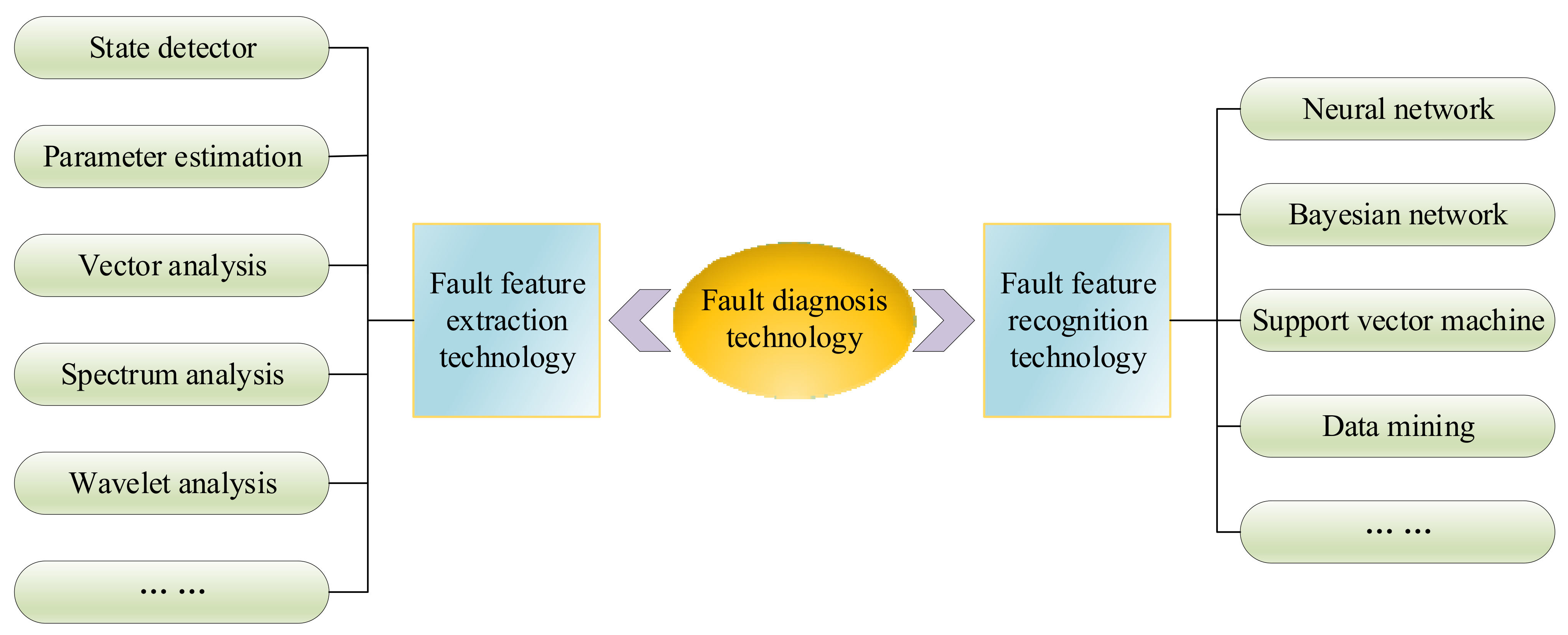
3. Fault Diagnosis of HVDC Transmission Systems

Although HVDC transmission systems have many advantages, it is always a challenge for researchers to provide fast and reliable protection. Efficient fault diagnosis will help to adopt reasonable measures to minimize the negative impact of faults. At present, HVDC operation and maintenance face constraints. There is a lack of effective technical support for operation and maintenance management. It is difficult to further improve the efficiency of traditional artificial means. It is urgent to find a new driving force to reach high-quality security and development by combining digital transformation and intelligent technology applications. Meanwhile, HVDC fault analysis lacks intelligent methods. The state assessment, fault analysis, and disposal of HVDC systems are highly dependent on the operation and maintenance experience and skill level of on-site disposal personnel. There is a lack of effective intelligent analysis means and expert support systems, and intelligent analysis and auxiliary decision-making means are seriously insufficient.
Fault diagnosis technology is divided into fault feature extraction technology and faults feature recognition technology. The classification structure diagram is shown in Figure 2. Compared to traditional troubleshooting methods, AI-based fault diagnosis methods are widely preferred by researchers because of their merits such as high reliability and small communication requirements, which is also a promising tool for solving HVDC fault diagnosis [41]. Therefore, this work mainly introduces and summarizes the fault diagnosis methods of HVDC systems based on AI.
With the increase in HVDC system scale and fault sample points, the operation reliability of HVDC systems is confronted with severe challenges. At present, the fast development of neural networks has strongly promoted the research of pattern recognition and data mining [42]. In reference [43], a fault diagnosis method based on spectral kurtosis deconvolution for air valve air coolers in UHVDC transmission is proposed, which solves the issue of it being challenging to effectively diagnose early composite faults of air cooler motors in the humid, corrosive, and external vibration environment. Reference [44] proposes a fault diagnosis approach based on a parallel convolutional neural network (PCNN). Reference [45] uses convolutional neural networks (CNN) to detect and classify DC faults. This method makes full use of the strengths of CNN in image feature extraction, and the recognition accuracy reaches 92.5%. Reference [46] proposes a method based on an artificial neural network (ANN) to achieve DC bus protection and line protection of the power grid. The discrete wavelet transform is used as the feature extractor at the input of the network. The input is the frequency range component and the time range component. The output of the network is used to trigger protection. The overall protection flow of this method is shown in Figure 3. However, compared with the traditional fault diagnosis technology, deep learning has its own distinctive shortcomings, for instance, it usually requires a lot of data and brings higher computing costs, which makes it difficult to extend to practical application. Meanwhile, the black box nature of the deep learning network makes it difficult to explain the fault diagnosis process and determine whether the fault diagnosis extraction is complete. Therefore, the current fault diagnosis method based on deep learning is more suitable for on-site personnel’s auxiliary judgment means in practical projects [47]. In addition, to solve the complex data preprocessing problem, a new fault detection and location approach based on the bidirectional gated recursive unit is proposed in reference [48]. This method has obvious advantages in bi-directional structure feature extraction and simplifies fault data preprocessing.
To more accurately extract fault features, it is often necessary to preprocess the features, such as the Fourier transform, wavelet transform, and so on. The function of the Fourier transform is to transform a signal from the time range to the frequency range. With different ranges, the perspective of interpreting the same thing will also change, thus making the problem easier to deal with. The Fourier transform is shown in Equation (5).
F w = f t e i w t d t
where w is the frequency, t is the time, and e i w t is the complex variable function.
The wavelet transform inherits the idea of localization of short-time Fourier transform. In particular, it can deal with the problem that the window does not change with frequency. The wavelet analysis is widely used in fault feature extraction because it can provide localization information of the fault signal in the time range and frequency range, which remedies the shortcoming that Fourier transform cannot describe the fault signal in the time range and frequency range simultaneously and Fourier transform has the same resolution in the whole time-frequency plane for a short period of time. Reference [49] studies the fault diagnosis based on wavelet packet decomposition. It performs one-dimensional wavelet packet decomposition on the original fault signal of the inverter, extracts the energy value of the fault signal in each frequency band as the feature information, and then forms an effective fault feature vector as the input vector of the fault classifier, which realizes fault location. At present, the main steps of applying the wavelet packet decomposition method to fault feature extraction are as follows:
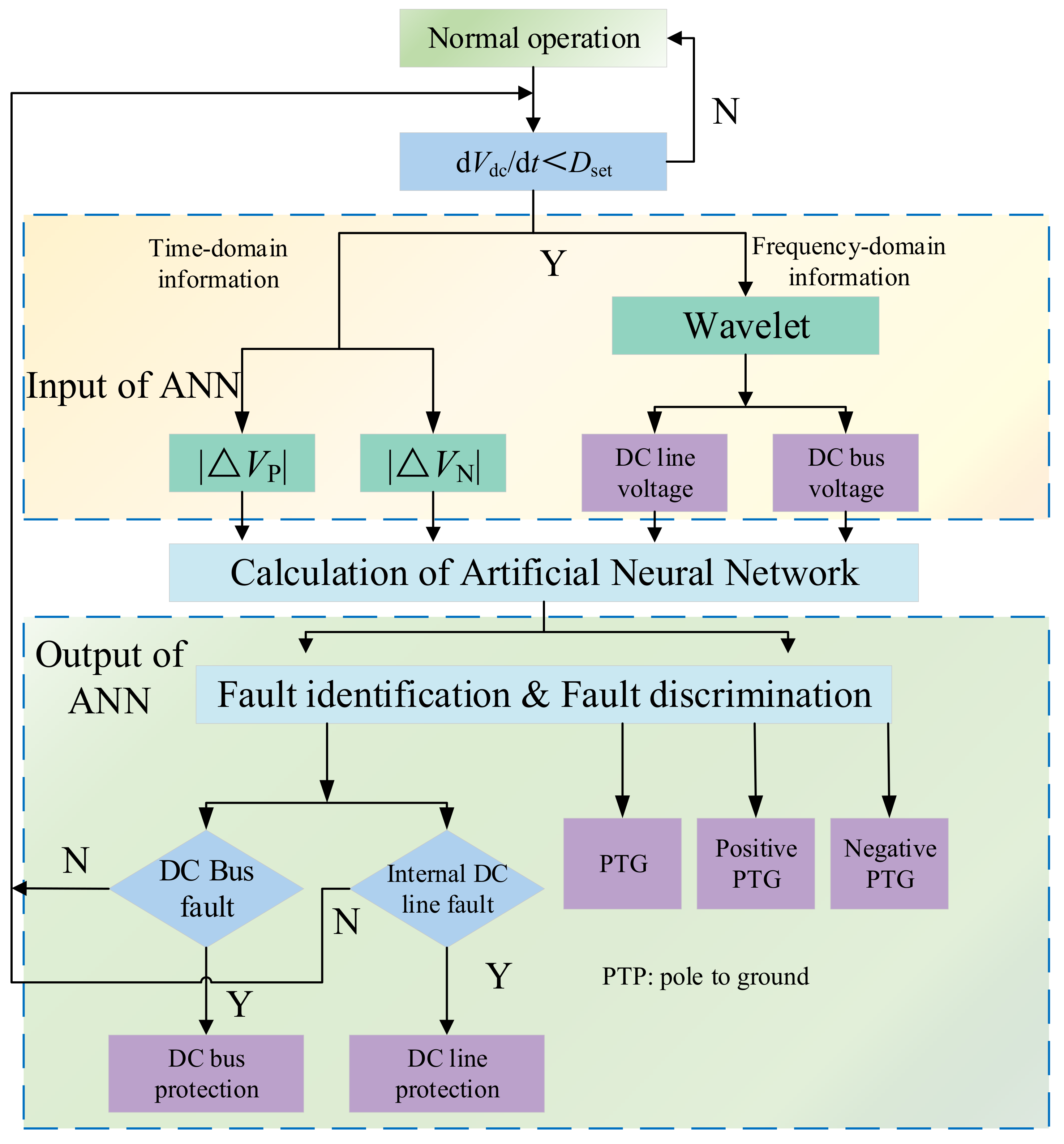
  • The three-phase current or voltage at the AC side of the inverter in one fundamental wave period is sampled as the fault signal;
  • The fault signal is decomposed by an n-layer wavelet packet, and the wavelet packet coefficients at the node (j + 1, p) are given by Equation (6), where h 0 (k) and h 1 (k) are a pair of conjugate orthogonal filters, which can be obtained by wavelet basis function calculation;
  • The wavelet packet coefficient d j p at the node (j, p) is reconstructed to obtain the reconstructed wavelet packet coefficient D j , p (k) of the node;
  • Calculate the energy value E n , p at the pth node of the nth layer according to Equation (7), where l is the number of data points sampled in one fundamental wave period;
  • Obtain the percentage T n , p of the energy value of each frequency interval in the total energy value according to Equation (8) and select the percentage of the energy value of the first s nodes (0 < s < 2 n ) of the nth layer as the fault characteristic quantity.
d j + 1 2 p k = d j p k × h ¯ 0 2 k = m = d j p m h 0 m 2 k d j + 1 2 p + 1 k = d j p k × h ¯ 1 2 k = m = d j p m h 1 m 2 k
E n , p = k = 1 l D n , p k 2
E total = p = 1 2 n E n , p T n , p = E n , p E total
At present, most fault diagnosis methods are often combined with AI to achieve automatic classification and fault diagnosis. Generally, the model is established offline, and the established model is used for online feature recognition. Meanwhile, the research on fault feature recognition methods mainly focuses on neural networks, Bayesian networks, fuzzy logic reasoning, data mining, and so on.

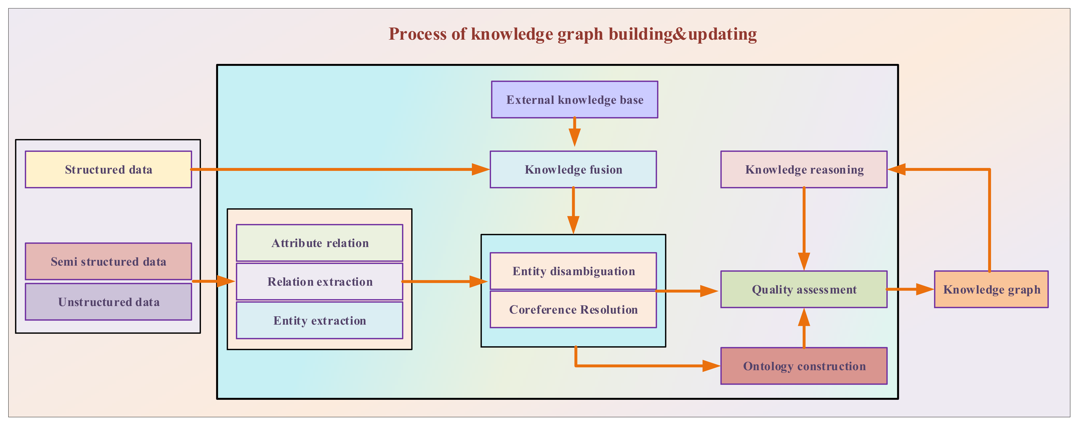
4. Fault Diagnosis Based on Knowledge Graph Technology

4.1. Knowledge Graph Technology

With the development of ultra-high pressure (UHV) power grids and renewable energy, power system faults are more complex and diverse, and the fault handling of the power system requires more and more comprehensive professional ability of operation personnel. Meanwhile, with the increasing volume of the power system and an increasing number of elements in the power system, the daily operation is not only satisfied with the application of data mining but it also faces a technical bottleneck in converting data into knowledge. Therefore, the power system needs to improve the experience and operation logic of the staff into knowledge through Internet technology, enrich the means of fault judgment and recovery decision, and help the regulator to control the key information of fault handling actively, rapidly, and comprehensively, and provide a corresponding subsidiarity decision for fault handling [50].
As a method of organizing and constructing knowledge based on AI technology, knowledge graphs are similar to the form of human cognition of the world, which can represent complex associative relationships at the semantic level and provide a higher ability to manage and understand huge amounts of information. By constructing the domain knowledge graph of power grid fault processing, the value of multivariate heterogeneous data in power grid fault processing can be fully explored to solve the problems of low accuracy and poor timeliness of fault processing caused by the difference and lack of knowledge reserves of control and operation personnel. The knowledge graph is an effective way to improve the accident-handling ability of power grid regulators [51,52,53]. Triplet is a normal delegate of the knowledge graph, namely G = (E, R, S), where E is the set of entities in the knowledge base, R is the set of relations, and S is the set of triples. Neo4j, FlockDB, and other graph databases are generally used as storage media.
According to the application areas, knowledge graphs can be divided into general knowledge graphs and industry knowledge graphs. The general knowledge graph covers a wide range of content, focusing on a large number of entities, mainly for search, question answering, and other fields. The industry knowledge graph is only for a specific domain, according to the needs and characteristics of the domain, to provide business functions or solve specific problems [54]. The architecture of the knowledge graph includes its logical structure and the technical architecture adopted in the construction process, as shown in Figure 4 [55]. The knowledge graph framework consists of the following four processes.
Knowledge extraction: Knowledge extraction is divided into three main steps: term extraction, relationship extraction, and concept extraction. The implementation of term extraction mainly includes four-term extraction methods based on dictionaries, rules, statistics, and machine learning. The technical difficulty of relationship extraction lies in the extraction of synonymous relationships. At present, the mainstream concept extraction methods are based on linguistics or statistics [24,56].
Knowledge representation learning: Knowledge must be reasonably represented before it can be processed by the computer [57]. Thereafter, many scholars improved and suggested PTransE, RotatE, and RDF attribute graph models. Furthermore, several novel approaches have been proposed by scholars to address the difficulties of some specific conditions in particular areas, such as the JAPE model, ConvE model, MTransE model, and BootEA model [24].
Knowledge mining: Knowledge mining refers to the use of link prediction, neural network technology, and the decision tree method of knowledge map implicit knowledge mining and supplement, which is the technical foundation of knowledge reasoning and fusion. It is essential in the process of large-scale knowledge map construction technology, which mainly can be divided into three branches: clues to mining, inference, and prediction [58].
Knowledge reasoning and fusion: It refers to the operation of improving and expanding knowledge graphs and updating knowledge graphs in real-time by deep mining the implicit relationship between old knowledge and new knowledge within the same knowledge graph or between different knowledge graphs, which is the most core step in the construction of knowledge graphs. In the process of building a knowledge graph, it is often necessary to obtain data from multiple sources, and these data from different sources may be crossed, overlapped, and repeated. The purpose of knowledge fusion is to extract useful knowledge and insights from massive data, so as to fuse the knowledge from different sources into a knowledge base [59].

4.2. Knowledge Graph Technology in Power System

Currently, the application of knowledge graphs in the electric power field has been explored at home and abroad. Meanwhile, knowledge graph technology is mainly used in power system regulation operation and fault diagnosis [60]. Reference [61] builds the knowledge graph of power equipment through the data of power equipment to improve the management efficiency of power equipment. Reference [62] puts forward the construction method of knowledge graphs in the direction of power grid regulation to be applied in the scenario of fault disposal. Reference [63] proposed a knowledge graph construction method for the topology structure of low-voltage distribution networks. By integrating and mining the information system data of multiple low-voltage distribution networks, the identification of the household variation relationship of low-voltage distribution networks in the system was realized. Reference [64] builds a knowledge graph of dispatching automation system, to help operation and maintenance personnel understand the internal structure and business logic of the scheduling automation system.
In terms of the research of fault diagnosis and fault analysis of power systems, reference [65] built the knowledge graph of power equipment defects through the text of power equipment defect records to realize the retrieval of similar fault records. Reference [51] puts forward a multi-level and multi-category knowledge graph application framework for power grid fault processing auxiliary decision-making and preliminarily expounds the key technologies and solutions of functions within the framework. Reference [55] analyzed historical cases of cable faults and processed structured data, extracted relevant fault characteristic information, constructed a cable fault knowledge graph, and then used AI technology to establish a cable fault diagnosis system to achieve rapid analysis and diagnosis of cable line faults. Reference [24] puts forward an approach for building a fault knowledge graph of substation alarm information. The constructed grid accident behavior graph is shown in Figure 5. This method introduces knowledge graph technology to knowledge mining of substation alarm information.
In addition, in recent years, equipment fault diagnosis technology based on the deep learning model has also received a wide range of concerns and research efforts [66,67]. In reference [68], a multi-modal semantic model based on deep learning and knowledge graph is proposed by combining knowledge graph technology with the deep learning model. The overall framework of the model is shown in Figure 6, which mainly includes the construction and application of a multi-modal knowledge graph and the application of the YOLOv4 target detection algorithm. Simulation results show that this approach can achieve the goal of intelligent fault diagnosis decisions and improve the efficiency of daily operation, maintenance, and management of power grids.
At present, the HVDC transmission system still largely relies on equipment monitoring and manual analysis, and the fault anomaly analysis lacks intelligent means. The status assessment, fault analysis, and disposal of the DC system highly depend on the operation and maintenance experience and skill level of on-site disposal personnel [69]. With the intelligent upgrading and digital transformation of power equipment, advanced information transmission, widely deployed sensors, and various management platforms have accumulated a large amount of DC system-related data. On this basis, an AI-assisted decision service platform for operation and maintenance of DC equipment based on this knowledge base is developed. By preprocessing the data, the fault characteristic signal is extracted, and then the fault characteristic signal is judged by the knowledge base, so as to determine whether the power equipment is faulty and feed back to the service platform [70].

5. Discussion

At present, with the larger scale of HVDC transmission systems in the current power system, there are a variety of challenges, such as the lack of effective management of massive data, insufficient intelligent fault analysis methods, etc. In order to realize the knowledge graph technology-based intelligent fault diagnosis of HVDC transmission systems, the following requirements should be satisfied.
  • Data acquisition: (a) Reliable data quality; (b) High data accuracy; (c) Large data volume; (d) Sufficient data type.
  • Data transmission: (a) High data transmission speed; (b) Low data lost during transmission; (c) Low transmission noises.
  • Data processing: (a) Online processing capability; (b) Fast processing rate; (c) Secure processing environment.
It is necessary to build a large number of knowledge bases according to the characteristics of knowledge graph technology. However, since the safe and reliable operation should always be the first and foremost demand due to the particularity of HVDC transmission engineering, the actual fault data of HVDC systems are hard to collect to build sufficient knowledge bases. In order to obtain enough data, various types of HVDC fault data must be obtained through a large number of simulation experiments and hardware-in-the-loop (HIL) experiments. When analyzing the behavior characteristics of HVDC systems in a fault state, an appropriate simulation model will be beneficial to balance its accuracy and complexity. Generally, the LCC-HVDC simulation model can be divided into quasi-steady state model, dynamic phasor model, and electromagnetic transient model. The quasi-steady state model has the least amount of calculation, but its accuracy is relatively low. The accuracy of dynamic phasor model and electromagnetic transient model is higher, but also brings an increasing computation burden. The simulation model of VSC-HVDC can be divided into the device detailed model, device simplified model, variable resistance model, and average value model. The device detailed model has the highest accuracy; however, it is too complex to be applied to large system scenarios. The calculation amount of the simplified device model, variable resistance model, and average model are all comparatively reduced, which is more suitable for most scenarios [71,72].
In addition, with the increasing number of sensors equipped in the power system, the monitoring data of power equipment sensors are characterized by unstable sample quality and few fault samples. Digital twin technology can be used to comprehensively monitor the operation status of equipment [73,74,75]. Digital twin is actually a simulation process that makes full use of the physical model, sensor update, operation history, and other data, and then integrates multidisciplinary, multi-physical quantity, multi-scale, and multi-probability factors. Then, it completes mapping in virtual space, thus reflecting the full life cycle process of corresponding physical equipment [76,77]. Digital twin technology is based on the dynamic and real-time physical entities of power equipment, and thus constructs a virtual digital model that is fully mapped with its spatial range and time scale. Combined with the multi-source monitoring data of power equipment, the virtual model can simulate the dynamic and real-time changes of large-scale power equipment and monitor the operation status of power equipment in the power system in a panoramic way to improve the ability of fault perception and fault diagnosis under fault conditions [78].
At present, the research of HVDC transmission systems based on knowledge graph technology is relatively blank. Meanwhile, the application of knowledge graphs in power systems is still in its infancy stage, the application scenarios are not clear, and the key technologies such as the construction of knowledge graphs, knowledge reasoning, and graph completion lack in-depth research. In this work, a new fault diagnosis method for HVDC transmission systems is proposed based on knowledge graph technology. The overall framework is shown in Figure 7. According to the fault information, this approach studies DC system state identification and fault inference analysis technology based on a small sample and graph neural network, and then builds an interpretable DC fault inference model combined with a DC knowledge package to realize typical fault analysis, fault location inference, risk analysis, and recommendation push. The data used for this framework are mainly from both the actual operation data and simulation data. The simulation data are mainly generated based on power systems computer-aided design (PSCAD) software. According to the actual engineering design structure, number of groups, and parameters, the components of PSCAD are used to build in detail. This paper considers that a Bayesian network can deal with uncertainty problems well and it also can effectively express and fuse multi-source information. Therefore, the fault diagnosis framework proposed in this work incorporates various components of fault diagnosis and solutions into the network structure through the Bayesian network and performs unified processing and integration based on the relevance of the content [79,80].

6. Conclusions and Prospects

The safe operation of HVDC systems plays a crucial role in solving the imbalance of resource distribution and realizing the maximum efficiency of energy utilization. Meanwhile, fast and accurate fault diagnosis is the key to ensure the continuous power supply of long-distance HVDC transmission lines. The current fault diagnosis methods for HVDC transmission systems are comprehensively summarized and analyzed in this work, which contribution is concluded as follows:
(1)
Converter station fault and DC line fault of HVDC transmission systems are summarized and analyzed, respectively. The adverse effects that can be caused by all fault types are also discussed;
(2)
With the rapid development of AI technology, it has been widely concerned and applied in the areas of fault diagnosis. The prior fault analysis and diagnosis of power systems based on knowledge graph technology are summarized and analyzed comprehensively;
(3)
Finally, based on knowledge graph technology, a new fault diagnosis framework for HVDC transmission systems is proposed.
With the intelligent upgrading and digital transformation of equipment in power systems, there will be great changes in equipment operation inspection, maintenance, production command, and decision making. A large number of intelligent terminals and massive amounts of new data have brought new challenges to the technical skills of production personnel. The role of production personnel needs to be changed and their ability needs to be improved. Future research on fault diagnosis of HVDC can be carried out in the following directions.
(1)
Knowledge graphs can be used to construct the whole system to establish the whole life cycle analysis and evaluation of the power grid;
(2)
Digital twin technology can be used to simulate the operation state of the whole system to analyze and estimate the potential faults;
(3)
More equipment state measurement devices can be added to achieve the construction of transparent power grids;
(4)
Accelerated integration of various advanced AI algorithms for fault diagnosis to satisfy specific requirements, and thus to achieve the construction of digital power grids;
(5)
The industrial knowledge graph needs to make further breakthroughs in the deep semantic representation of logical relations, causal relations, and turning relations;
(6)
Since AI techniques can effectively simplify solutions’ complexity and enhance self-learning ability, they can be used to deal with highly nonlinear and multiple correlation problems. Meanwhile, the time series or correlation prediction model is established to improve the efficiency and accuracy of the operation state prediction of power equipment;
(7)
An HVDC fault diagnosis network based on a cloud computing service platform is one feasible and promising application to diagnose fault data in the “cloud”, which can improve the data and information processing speed.

Funding

The authors gratefully acknowledge the support of Key Science and Technology Projects of China Southern Power Grid Company Limited (CGYKJXM20210309).

Conflicts of Interest

The authors declare no conflict of interest.

References

  1. Electricity Market Report. International Energy Agency. Paris. 2022. Available online: https://www.iea.org/reports/electricity-market-report-january-2022 (accessed on 2 September 2022).
  2. Shrestha, A.; Mustafa, A.A.; Htike, M.M.; You, V.; Kakinaka, M. Evolution of energy mix in emerging countries: Modern renewable energy, traditional renewable energy, and non-renewable energy. Renew. Energy 2022, 199, 419–432. [Google Scholar] [CrossRef]
  3. Digital grid promotes the construction of a new power system with new energy as the main body of the white paper. In Proceedings of the China Southern Power Grid Corporation, Guangzhou, China, 1 August 2021–31 July 2022.
  4. Li, P.P.; Zhou, H.Y.; Yao, W.; Wang, L.R.; Yang, C.X.; Li, C.H.; Wen, J.Y. Review of commutation failure on HVDC transmission system under background of multi-infeed structure. Power Syst. Technol. 2022, 46, 834–850. [Google Scholar] [CrossRef]
  5. Wang, D.; Fu, J.H.; Hou, M.Q.; Qiao, F.; Gao, M.Y. Novel travelling wave fault location principle for VSC-HVDC transmission line. Electr. Power Syst. Res. 2021, 196, 107226. [Google Scholar] [CrossRef]
  6. Benasla, M.; Allaoui, T.; Brahami, M.; Denaï, M.; Sood, V.K. HVDC links between north Africa and Europe: Impacts and benefits on the dynamic performance of the European system. Renew. Sustain. Energy Rev. 2018, 82, 3981–3991. [Google Scholar] [CrossRef] [Green Version]
  7. Wang, W.S.; Li, G.H.; Guo, J.B. Large-scale renewable energy transmission by HVDC: Challenges and proposals. Engineering 2022. [Google Scholar] [CrossRef]
  8. Pierri, E.; Binder, O.; Hemdan, N.G.A.; Kurrat, M. Challenges and opportunities for a European HVDC grid. Renewable and Sustain. Energy Rev. 2017, 70, 427–456. [Google Scholar] [CrossRef]
  9. Stefanidou-Voziki, P.; Sapountzoglou, N.; Raison, B.; Dominguez-Garcia, J.L. A review of fault location and classification methods in distribution grids. Electr. Power Syst. Res. 2020, 209, 108031. [Google Scholar] [CrossRef]
  10. Song, W.H.; Lin, L.; Xu, C.; He, Z. Characteristics of single-pole to ground fault of a two-terminal hybrid HVDC system. South. Power Syst. Technol. 2018, 12, 44–51. [Google Scholar] [CrossRef]
  11. Tang, Y.; Zheng, C.Y. Review on influencing factors of commutation failure in HVDC systems. Proc. CSEE 2019, 39, 499–513. [Google Scholar] [CrossRef]
  12. Lin, S.; Liu, J.; Liu, L.; Lei, Y.Q.; Fu, C. A review of commutation failure suppression methods for HVDC systems based on control protection measures. Proc. CSEE 2020, 40, 6045–6058. [Google Scholar] [CrossRef]
  13. Jing, L.M.; Wang, B.; Dong, X.Z.; Wang, H.G.; Yu, B.; Xie, M.; Chen, S. Review of consecutive commutation failure research for HVDC transmission system. Electr. Power Autom. Equip. 2019, 39, 116–123. [Google Scholar] [CrossRef]
  14. Song, J.Z.; Li, Y.L.; Zeng, L.; Zhang, Y.K. Review on commutation failure of HVDC transmission system. Autumation Electr. Power Syst. 2020, 44, 2–13. [Google Scholar] [CrossRef]
  15. Zhu, H.Y.; Yao, W.; Ai, X.M.; Li, D.H.; Wen, J.Y.; Li, C.H. Comprehensive review of commutation failure in HVDC transmission systems. Electr. Power Syst. Res. 2022, 205, 107768. [Google Scholar] [CrossRef]
  16. Lei, Z.Y.; Hao, L.S.; Dai, J.S.; Zhang, L.; Wang, X.; Cui, C.; Qi, J.; Tang, X. A review of fault location methods in HVDC transmission lines. Power Syst. Prot. Control 2022, 50, 178–187. [Google Scholar] [CrossRef]
  17. Yang, L.; Wang, B.; Dong, X.Z. Overview of fault location methods in high voltage direct current transmission lines. Autom. Electr. Power Syst. 2018, 42, 185–191. [Google Scholar] [CrossRef]
  18. Peng, T.; Tzelepis, D.; Dysko, A.; Glesk, I. Assessment of fault location techniques in voltage source converter based HVDC systems. In Proceedings of the IEEE Texas Power and Energy Conference (TPEC), College Station, TX, USA, 9–10 February 2017. [Google Scholar]
  19. Yang, H.Q.; Wang, W.; Jing, L.; Wu, X.Z. Analysis on transient characteristic of dc transmission line fault in mmc based HVDC transmission system. Power Syst. Technol. 2016, 40, 40–46. [Google Scholar] [CrossRef]
  20. Ikhide, M.; Tennakoon, S.; Griffiths, A.; Subramanian, S.; Ha, H.X. Fault detection in multi-terminal modular multilevel converter (MMC) based high voltage DC (HVDC) transmission system. In Proceedings of the 2015 50th International Universities Power Engineering Conference (UPEC), Stoke on Trent, UK, 1–4 September 2015. [Google Scholar] [CrossRef] [Green Version]
  21. Li, J.W.; Yang, Q.Q.; Mu, H.; Blond, S.L.; He, H.W. A new fault detection and fault location method for multi-terminal high voltage direct current of offshore wind farm. Appl. Energy 2018, 220, 13–20. [Google Scholar] [CrossRef]
  22. Wang, S.; Bi, T.S.; Jia, K. Wavelet entropy based pole grounding fault detection approach for MMC-HVDC overhead lines. Power Syst. Technol. 2016, 40, 2179–2185. [Google Scholar] [CrossRef]
  23. Hong, G.; Lian, S.T.; Guo, M.F.; Gao, W. Application of empirical wavelet transform in fault detection of DC distribution system. Electr. Mach. Control 2021, 25, 65–74. [Google Scholar] [CrossRef]
  24. Lin, L.Y.; Chen, Q.; Jin, L.; Wang, L. Research and application of substation alarm signal fault knowledge representation based on knowledge graph. Power Syst. Prot. Control 2022, 50, 90–99. [Google Scholar] [CrossRef]
  25. Ma, A.; Yu, Y.H.; Yang, S.L.; Shi, C.; Li, J.; Cai, X.X. Survey of knowledge graph based on reinforcement learning. J. Comput. Res. Dev. 2022, 59, 1694–1722. [Google Scholar] [CrossRef]
  26. Li, G.; Li, Y.Q.; Wang, H.T.; Xie, Q.; Huang, W.Q.; Hou, J.X. Knowledge graph of power equipment health management: Basic concepts, key technologies and research progress. Autom. Electr. Power Syst. 2022, 46, 1–13. [Google Scholar] [CrossRef]
  27. Wang, L.L.; Cao, Y. Review of HVDC transmission technology. Sci. Technol. Innov. 2018, 10, 50–51. [Google Scholar]
  28. Tang, G.F.; Pang, H.; He, Z.Y. R&D and application of advanced power transmission technology in China. Proc. CSEE 2016, 36, 1760–1771. [Google Scholar] [CrossRef]
  29. Ni, X.J.; Zhao, C.Y.; Guo, C.Y.; Liu, Y.C. The effects of VSC-HVDC on the system strength of LCC-HVDC in dual-infeed hybrid HVDC system. Proc. CSEE 2015, 35, 4052–4061. [Google Scholar] [CrossRef]
  30. Zou, C.Y.; Wei, R.H.; Feng, J.J.; Zhou, Y.B. Development status and application prospect of VSC-HVDC. South. Power Syst. Technol. 2022, 16, 1–7. [Google Scholar] [CrossRef]
  31. China Southern Grid Ultra High Voltage Transmission Co. Typical Fault Analysis of HVDC Transmission System Equipment; China Electric Power Press: Beijing, China, 2009; Volume 12. [Google Scholar]
  32. Li, X.Y. High Voltage Direct Current Transmission System; Science Press: Beijing, China, 2010; Volume 2. [Google Scholar]
  33. Qi, Y. The Fault Analysis of HVDC System and the Study of It’s Transmission Line Protection Scheme; East China Jiaotong University: Nanchang, China, 2012. [Google Scholar]
  34. Liu, L.; Lin, S.; He, Z.Y. A novel method based on virtual commutation area insufficient to mitigate the continuous commutation failure for HVDC. Proc. CSEE 2018, 38, 5361–5368. [Google Scholar] [CrossRef]
  35. Guo, J.M. Research on Fault Analysis and Protection of High-Voltage Direct Current Transmission Lines; South China University of Technology: Guangzhou, China, 2016. [Google Scholar]
  36. Li, A.M. A Study on Fault Analysis and Protection of the HVDC Transmission Line; South China University of Technology: Guangzhou, China, 2010. [Google Scholar]
  37. Zhang, F.G.; Wen, M.H.; Liu, T.; Wang, X.Z.; Yang, D.X.; Wu, T. Establishment of dynamic physical model of three-terminal UHV DC transmission line. High Volt. Eng. 2020, 46, 2064–2071. [Google Scholar] [CrossRef]
  38. Zhang, C.H.; Song, G.B.; Dong, X.Z. Principle of non-unit traveling wave protection for VSC-HVDC transmission line using fault current initial traveling wave fitting. Proc. CSEE 2021, 41, 2651–2660. [Google Scholar] [CrossRef]
  39. Wang, Z.Z.; Liu, K.; Li, M.Y.; Li, B.; Xu, J.W.; Zhao, J.C. Co-simulation and analysis of “Three Transformers” for UHV transformer under DC-bias. High Volt. Eng. 2020, 46, 4097–4105. [Google Scholar] [CrossRef]
  40. Tong, Y.; Zhu, Q.L.; He, L.; Zhao, X.J. Analysis on DC bias impact on converter transformers operation. High Volt. Eng. 2021, 47, 2206–2213. [Google Scholar] [CrossRef]
  41. Fahim, S.R.; Sarker, S.K.; Muyeen, S.M.; Das, S.K.; Kamwa, I. A deep learning based intelligent approach in detection and classification of transmission line faults. Int. J. Electr. Power Energy Syst. 2021, 133, 107102. [Google Scholar] [CrossRef]
  42. Wu, Z.H.; Pan, S.R.; Chen, F.W.; Long, G.D.; Zhang, C.Q.; Yu, P.S. A comprehensive survey on graph neural networks. IEEE Trans. Neural Netw. Learn. Syst. 2021, 32, 4–24. [Google Scholar] [CrossRef] [PubMed] [Green Version]
  43. Li, Y.; Li, J.; Guo, C.H.; Dang, J. Fault diagnosis method of converter valve air cooler based on spectral kurtosis deconvolution. Power Syst. Clean Energy 2021, 37, 48–61. [Google Scholar]
  44. Wang, H.; Yang, D.S.; Zhou, B.W.; Gao, X.T.; Pang, Y.H. Fault diagnosis of multi-terminal HVDC transmission line based on parallel convolutional neural network. Autom. Electr. Power Syst. 2019, 44, 84–92. [Google Scholar] [CrossRef]
  45. Wang, J.; Zheng, X.D.; Tai, N.L. DC fault detection and classification approach of MMC-HVDC based on convolutional neural network. In Proceedings of the 2018 2nd IEEE Conference on Energy Internet and Energy System Integration (EI2), Beijing, China, 20–22 October 2018. [Google Scholar] [CrossRef]
  46. Wang, X.; Yang, S.Z.; Wen, J.Y. ANN-based robust DC fault protection algorithm for MMC high-voltage direct current grids. IET Renew. Power Gener. 2019, 14, 199–210. [Google Scholar] [CrossRef] [Green Version]
  47. Zhao, J.Q.; Xie, X.; Xu, C.L.; Hu, W.; Shang, X.W. Review on application of new generation artificial intelligence technology in power system dispatching and operation. Autom. Electr. Power Syst. 2020, 44, 1–9. [Google Scholar] [CrossRef]
  48. Wang, Y.T.; Zheng, D.K.; Jia, R. Fault diagnosis method for MMC-HVDC based on Bi-GRU neural network. Energies 2022, 15, 994. [Google Scholar] [CrossRef]
  49. Jiang, C.; Wang, Q.; Gong, C.Y. Inverter power switch fault diagnosis technique research based on wavelet and concordia transform. Proc. CSEE 2015, 35, 3110–3116. [Google Scholar] [CrossRef]
  50. Lu, G.H.; Yu, T.; Chen, J.B.; Ding, M.S.; Yang, H.B. Application and prospective of knowledge graph in power system dispatching operation. Electr. Power ICT 2022. Available online: https://kns.cnki.net/kcms/detail/10.1164.TK.20220909.1407.009.html (accessed on 20 September 2022).
  51. Qiao, J.; Wang, X.Y.; Min, R.; Bai, S.H.; Yao, D.; Pu, T.J. Framework and key technologies of knowledge-graph-based fault handling system in power grid. Proc. CSEE 2020, 40, 5837–5848. [Google Scholar] [CrossRef]
  52. Yang, N.; Zhang, G.G.; Wang, J. Research on knowledge graph and Bayesian network in fault diagnosis of steam turbine. In Proceedings of the 2020 Global Reliability and Prognostics and Health Management (PHM-Shanghai), Shanghai, China, 16–18 October 2020. [Google Scholar] [CrossRef]
  53. Feng, Y.; Zhai, F.; Li, B.F.; Cao, Y.F. Research on intelligent fault diagnosis of power acquisition based on knowledge graph. In Proceedings of the 2019 3rd International Conference on Electronic Information Technology and Computer Engineering (EITCE), Xiamen, China, 18–20 October 2019. [Google Scholar] [CrossRef]
  54. Tian, L.; Zhou, X.; Wu, Y.P.; Zhou, W.T.; Zhang, J.H.; Zhang, T.S. Knowledge graph and knowledge reasoning: A systematic review. J. Electron. Sci. Technol. 2022, 20, 159–186. [Google Scholar] [CrossRef]
  55. Deng, X.B.; Fei, W.L. Analysis of cable fault diagnosis based on knowledge map. Mod. Inf. Technol. 2022, 4, 148–151. [Google Scholar] [CrossRef]
  56. Huang, H.Q.; Yu, J.; Liao, X.; Xi, Y.J. Review on knowledge graphs. Comput. Syst. Appl. 2019, 28, 1–12. [Google Scholar] [CrossRef]
  57. Hu, X.Y.; Wang, Z.Z.; Sun, Y.Y.; Xu, B.; Lin, H.F. Knowledge graph representation method combined with semantic parsing. J. Comput. Res. Dev. 2022. [Google Scholar] [CrossRef]
  58. Wang, Y.Z.; Jia, Y.T.; Liu, D.W.; Jin, X.L.; Cheng, X.Q. Open web knowledge aided information search and data mining. J. Comput. Res. Dev. 2015, 52, 456–474. [Google Scholar] [CrossRef]
  59. Nguyen, H.L.; Vu, D.T.; Jung, J.J. Knowledge graph fusion for smart systems: A survey. Inf. Fusion 2020, 61, 56–70. [Google Scholar] [CrossRef]
  60. Guo, R.; Yang, Q.; Liu, S.H.; Li, W.; Yuan, X.; Huang, X.H. Construction and application of power grid fault handing knowledge graph. Power Syst. Technol. 2021, 45, 2092–2100. [Google Scholar] [CrossRef]
  61. Tang, Y.C.; Liu, T.T.; Liu, G.Y.; Li, J.; Dai, R.C.; Yuan, C. Enhancement of power equipment management using knowledge graph. In Proceedings of the 2019 IEEE Innovative Smart Grid Technologies-Asia (ISGT Asia), Chengdu, China, 21–24 May 2019. [Google Scholar] [CrossRef]
  62. Yu, J.M.; Wang, X.H.; Zhang, Y.; Liu, Y.; Zhao, S.A.; Shan, L.F. Construction and application of knowledge graph for intelligent dispatching and control. Power Syst. Prot. Control 2020, 48, 29–35. [Google Scholar] [CrossRef]
  63. Gao, Z.P.; Zhao, Y.; Yu, Y.L.; Luo, Y.J.; Xu, Z.W.; Zhang, L.M. Low-voltage distribution network topology identification method based on knowledge graph. Power Syst. Prot. Control 2020, 48, 34–43. [Google Scholar] [CrossRef]
  64. Li, X.P.; Xu, J.H.; Guo, Z.M.; Li, J.L.; Ning, W.Y.; Wang, Z.X. Construction and application of knowledge graph of power dispatching automation system. Electr. Power 2019, 52, 70–77, 157. [Google Scholar] [CrossRef]
  65. Liu, Z.Q.; Wang, H.F. Retrieval method for defect records of power equipment based on knowledge graph technology. Autom. Electr. Power Syst. 2018, 42, 158–164. [Google Scholar] [CrossRef]
  66. Lin, W.S.; Wang, X.J.; Sun, Q.K.; Liu, Z.; He, J.H.; Pu, T.J. Dynamic dispatch of an integrated energy system based on deep reinforcement learning in an uncertain environment. Power Syst. Prot. Control 2022, 50, 50–60. [Google Scholar] [CrossRef]
  67. Wang, K.; Yao, J.G.; Yu, P.Y.; Yang, S.C.; Zhong, H.W.; Yan, J.H. Architecture and key technologies of intelligent decision-making of power grid look-ahead dispatch based on deep reinforcement learning. Proc. CSEE 2022, 42, 5430–5438. [Google Scholar] [CrossRef]
  68. Xiao, F.L.; Wu, Y.Z.; Shen, X.H.; He, Z.K.; Qin, Y. Intelligent fault diagnosis of substation equipment on the basis of deep learning and knowledge graph. Electr. Power Constr. 2022, 43, 66–74. [Google Scholar]
  69. Pu, T.J.; Qiao, J.; Han, X.; Zhang, G.B.; Wang, X.Y. Research and application of artificial intelligence in operation and maintenance for power equipment. High Volt. Eng. 2020, 46, 369–383. [Google Scholar] [CrossRef]
  70. Fan, S.X.; Li, L.X.; Wang, S.Y.; Liu, X.W.; Yu, Y.J.; Hao, B.W. Application analysis and exploration of artificial intelligence technology in power grid dispatch and control. Power Syst. Technol. 2020, 44, 401–411. [Google Scholar] [CrossRef]
  71. Zheng, W.; Guo, J.B.; Yang, G.Y.; Cao, R.B.; Nie, S.X.; Li, G.Y. A practical model suitable for DC fault simulation of a multi terminal DC transmission system. Power Syst. Prot. Control 2022, 50, 180–187. [Google Scholar] [CrossRef]
  72. Yu, Y.X.; Liu, T.Q.; Wang, S.L.; Peng, Q.; Wang, F. Small signal modeling of two-terminal MMC-HVDC based on AVM model. Proc. CSEE 2018, 38, 2999–3007. [Google Scholar] [CrossRef]
  73. Jia, W.J.; Wang, W.; Zhang, Z.Z. From simple digital twin to complex digital twin Part I: A novel modeling method for multi-scale and multi-scenario digital twin. Adv. Eng. Inform. 2022, 53, 101706. [Google Scholar] [CrossRef]
  74. Zhao, P.; Pu, T.J.; Wang, X.Y.; Han, X. Key technologies and perspectives of power internet of things facing with digital twins of the energy internet. Proc. CESS 2022, 42, 447–457. [Google Scholar] [CrossRef]
  75. Xiang, C.M.; Zeng, S.M.; Yan, P.; Zhao, J.L.; Jia, B.Y. Typical application and prospect of digital twin technology in power grid operation. High Volt. Eng. 2021, 47, 1564–1575. [Google Scholar] [CrossRef]
  76. Qi, B.; Zhang, P.; Zhang, S.Q.; Zhao, L.J.; Wang, H.B.; Huang, M.; Tang, Z.G.; Ji, M.; Li, C.R. Application status and development prospects of digital twin technology in condition assessment of power transmission and transformation equipment. High Volt. Eng. 2021, 47, 1522–1538. [Google Scholar] [CrossRef]
  77. Wang, Z.R.; Gupta, R.; Han, K.; Wang, H.X.; Ganlath, A.; Ammar, N.; Tiwari, P. Mobility digital twin: Concept, architecture, case study, and future challenges. IEEE Internet Things J. 2022, 9, 17452–17467. [Google Scholar] [CrossRef]
  78. Gao, S.G.; Zhou, M.; Zheng, W.; Zhang, L.X.; Zhang, B. Intelligent operation and maintenance for advanced equipment based on digital twin Challenges and future. Comput. Integr. Manuf. Syst. 2022, 28, 1953–1965. [Google Scholar] [CrossRef]
  79. Ma, M.Y.; Feng, L.; Sun, Y.R.; Li, F.; Zhang, X. Review of intelligent fault diagnosis methods for three-phase voltage-mode inverters. Proc. CESS 2020, 40, 7683–7698. [Google Scholar] [CrossRef]
  80. Hu, Y.C.; Li, T.; Cao, S.; Su, J.G.; Zhang, Y.H.; Li, Y.M. Research and application of parallel simulation of a UHVDC system based on PSCAD/EMTDC. Power Syst. Prot. Control 2021, 49, 178–186. [Google Scholar] [CrossRef]
Figure 1. Major fault points of a typical HVDC system.
Energies 15 08031 g001
Figure 2. Classification of fault diagnosis method.
Energies 15 08031 g002
Figure 3. Flow chart of fault detection.
Energies 15 08031 g003
Figure 4. Schematic of the knowledge graph architecture.
Energies 15 08031 g004
Figure 5. Construction process of power grid accident behavior graph.
Energies 15 08031 g005
Figure 6. Technical framework of the overall research.
Energies 15 08031 g006
Figure 7. Fault diagnosis flow chart.
Energies 15 08031 g007
Table 1. Characteristics of various fault diagnosis methods.
TypesAdvantageDisadvantageRobustness
Fault diagnosis based on analytical modelThis method can go deep into the nature of dynamic system. It can detect and diagnose faults in real time.It is difficult to establish an accurate mathematical model;
The simplification of the model can bring negative effects due to the limitations of the data itself.
General
Fault diagnosis based on signal processingThe difficulty of system modeling is avoided;
Strong practicability;
High sensitivity.
There is a time delay under certain conditions;
It is relatively difficult to analyze and interpret the fault.
Relatively strong
Fault diagnosis based on AIThe difficulty of system modeling is avoided;
Real-time fault detection;
High running speed.
Large demand for data.Strong
Table 2. Major fault points of a typical HVDC system.
Fault PointNumberFault Type
AC side1Converter transformer inlet failure
2Converter transformer outlet failure
3Converter valve AC side phase to phase failure
4Single-phase grounding fault on the AC side of the commutation valve
5Low voltage fault on the AC side of the converter valve
Converter valve6, 7, 8, 10, 11, 12Short circuit fault of converter valve
9, 13Ground fault of converter valve
DC side14, 15, 17DC line ground fault
16DC line positive grounding fault
18, 19Break-line fault
20Ground fault
21DC grounding electrode failure
22DC filter ground fault
23Capacitor fault
Table 3. Various faults and effects of HVDC transmission systems.
NameFault TypeLocation of FaultInfluence
AC system of rectifier sideOne-wire groundAC lineAn asymmetrical drop of AC voltage; the DC voltage and current may decrease accordingly and the non-characteristic harmonics increase.
Two-phase groundAC lineAn asymmetrical drop of AC voltage; the DC voltage and current may decrease accordingly and the non-characteristic harmonics increase.
Three-phase groundAC lineAn asymmetrical drop of AC voltage; the DC voltage and current may decrease accordingly.
Rectifier bridgeFalse firingBridge armDC voltage slightly rises (type I false firing) or decreases (type II false firing).
Not openBridge armDC voltage drop.
Component failureValve elementThe voltage applied to the element of the valve increases.
Bridge arm short circuitBridge armAC increases and DC goes down.
Outlet short circuitDC busAC increases and DC decreases to zero
DC lineOne-wire groundDC lineDC increases and an overvoltage occurs.
Two wire short circuitDC lineDC increases and an overvoltage occurs.
Switching overvoltageDC lineOvervoltage
Inverter bridgeFalse firingBridge armVoltage decreases and current increases.
Not openBridge armVoltage decreases and current increases.
Component failureValve elementThe voltage applied to the element of the valve increases.
Bridge arm short circuitBridge armVoltage decreases and current increases.
Outlet short circuitBridge armVoltage decreases and current increases.
AC system of inverter sideOne-wire groundAC lineWhen AC voltage drops asymmetrically, the commutation may fail and the non-characteristic harmonics may increase.
Two-phase short circuitAC lineWhen AC voltage drops asymmetrically, the commutation may fail and the non-characteristic harmonics may increase.
Three-phase short circuitAC lineWhen AC voltage drops asymmetrically, the commutation may fail.
Publisher’s Note: MDPI stays neutral with regard to jurisdictional claims in published maps and institutional affiliations.

