Article

Study on Critical Parameters of Nitrogen Injection during In Situ Modification in Oil Shale

1
School of Petroleum Engineering, China University of Geosciences, Wuhan 430074, China
2
State Key Laboratory of Shale Oil and Gas Enrichment Mechanisms and Effective Development, SINOPEC, Beijing 102206, China
3
Petroleum Exploration and Production Research Institute, SINOPEC, Beijing 102206, China
4
The First Oil Production Plant of Daqing Oilfield Corporation Limited, CNPC, Daqing 163000, China
*
Authors to whom correspondence should be addressed.
Energies 2022, 15(21), 8034; https://doi.org/10.3390/en15218034
Submission received: 20 September 2022 / Revised: 21 October 2022 / Accepted: 25 October 2022 / Published: 28 October 2022

Abstract

:
During in situ modification, inappropriate thermal insulation measures applied in annulus of injection wells will cause injection technical problems such as tremendous heat loss, wellhead lifting, serious casing damages, and corrosion. Continuous nitrogen injection into annulus is an effective measure to realize thermal insulation of injection wells. The critical displacement parameters of nitrogen injection in annulus are a key factor in the process of continuous nitrogen injection. However, the critical nitrogen injection rate under various working conditions, such as different well types, different wellhead steam parameters, and insulation pipe parameters, was not fully considered and studied. In this paper, the annular critical nitrogen injection displacement model was established based on the completion structure of injection well by applying the basic principles of heat transfer and fluid mechanics comprehensively. The influencing factors of critical nitrogen injection displacement were calculated and analyzed. The results show that the annular thermal resistance of horizontal wells is larger than that of directional wells for different well types, and the critical nitrogen injection displacement required is higher. The parameter sensitivity analysis shows that with the increase of pressure, steam displacement, and steam dryness, the required critical nitrogen injection displacement rate increases nearly quadratically. However, with the increase of the length and thermal conductivity of insulation pipe, the critical nitrogen injection displacement decreases cubically. The critical nitrogen injection can be reduced by reducing the annular area of the casing annulus and lowering the string deeply. The research results can provide key basic theoretical guidance for improving the heat utilization efficiency of in situ modified wells and reducing the casing damage rate for hot injection wells.

1. Introduction

The thermal insulation method used in the in situ thermal injection well has a great influence on the thermal injection efficiency; however, the continuous nitrogen supplement and heat insulation in annulus are the most economical and efficient [1,2,3]. The field monitoring results of the pilot test of the hot injection wells by the high-temperature optical fiber show that the continuous nitrogen annulus injection can keep the casing annulus sealed by the packer at a lower temperature range of 100–150 °C. Meanwhile, the temperature of casing annulus sealed by the packer can reach 200–250 °C when continuous nitrogen annulus injection is absent. Therefore, the continuous injection of quantitative nitrogen can reduce the decrease of accumulated injection heat due to the radial heat loss of formation [4,5]. Moreover, the wellhead lifting hazards due to the free section of casing caused by continuous high temperature can be reduced [6,7,8], the casing creep damage because of thermal stress concentration also can be depressed [9,10]. Moreover, it can also reduce the corrosion of the casing annulus [11,12].
The optimal design and calculation of the optimal nitrogen injection displacement are the key influencing factors, which directly affect the heat insulation effect when the continuous nitrogen injection heat insulation method is applied. If the nitrogen injection displacement is too low, part of the heat will return to the casing annulus above the injection port or the packer, which will increase wellbore heat loss and reduce injection heat utilization efficiency in result. However, if the nitrogen injection displacement is too high, it will cause unnecessary waste of nitrogen, and excessive cold nitrogen entering the wellbore will waste part of steam heat injected. The nitrogen insulation method in the annulus during steam injection was studied a lot. Valbuena et al. [13] studied the influence law on steam dryness, oil recovery, and gas–oil ratio of injection wells under the condition that the casing annulus insulation medium is nitrogen or water in the steam-assisted gravity drainage (SAGD) thermal recovery process. Teodoriu et al. [14] designed a self-expanding packer, which injected small discharge of nitrogen into the annulus to reduce the heat dissipation of the tubing and increase the steam dryness. Zhu [4], Sun [15], and Gao et al. [16] built a model of supercritical steam injection in the wellbore of heavy oil reservoir, and also the temperature, steam dryness, and steam pressure injected into general string, concentric double pipe string, and horizontal well were predicted and calculated respectively. Bo et al. [17] established a quantity demanded model of different fluids for casing annular injection, aiming at the problem of casing damage caused by the accumulation of annulus pressure in deep water wells, which control the accumulation of annulus pressure by injecting appropriate fluids. Ju et al. [18] constructed the steam quality variation model in the vertical section and horizontal section of steam-assisted gravity drainage (SAGD) horizontal injection gas well, and analyzed the influence of the vertical section, horizontal section and reservoir parameters on the steam quality. Gu et al. [19] proposed a new semi analytical model to predict the thermodynamic parameters of steam in the annulus, and compared it with the models of Sagar et al. [20], Alves et al. [21], Hasan et al. [22]. However, the previous researchers mainly studied the changes of steam thermodynamic parameters in the insulation pipe under static air insulation conditions. The influence of different insulation conditions in the annulus between the casing and the first injection string on the steam heat loss was not considered. At the same time, the model also does not systematically consider the impact of various working conditions such as different well types, different wellhead steam parameters, and insulation pipe parameters on the critical nitrogen injection displacement. Hence, in this paper, a model of critical nitrogen injection displacement was established, which was according to the completion structural characteristics of thermal recovery wells and based on the basic principles of heat transfer and fluid mechanics. Different influencing factors were analyzed and the process method of reducing nitrogen injection volume was defined. It can provide an important theoretical basis for high-efficiency nitrogen injection and heat insulation in the field application.

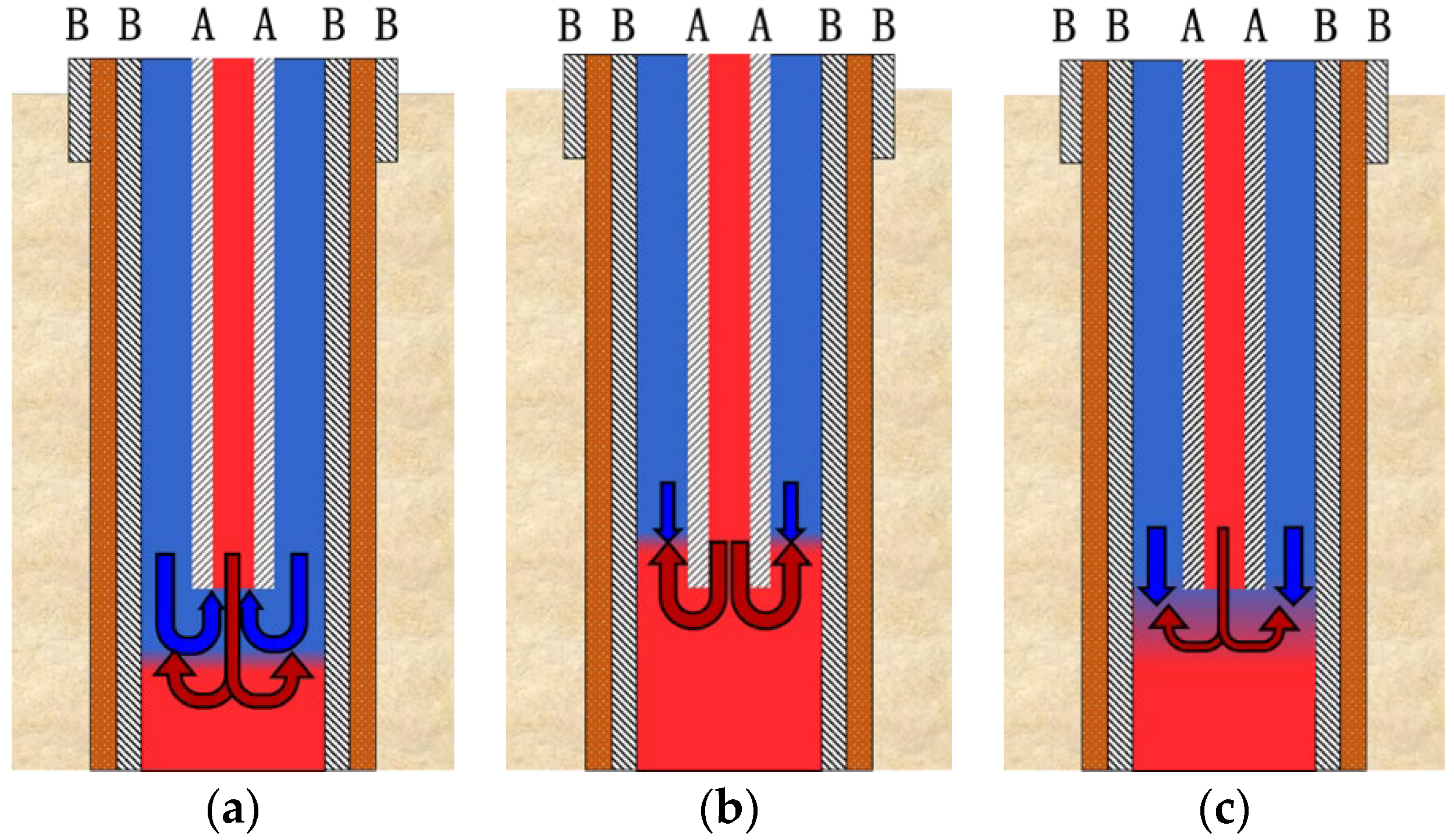
2. The Critical Injection of Nitrogen

The continuous nitrogen injection process in the casing annulus of hot injection well can effectively ensure that the casing protection section at the upper part of the wellbore is at a low temperature (<150 °C). However, the nitrogen injection displacement is affected and restricted by several factors, mainly including, reservoir porosity and permeability characteristics, well type, thermal insulation performance of thermal insulation pipe, and injected steam parameters. Therefore, a continuous nitrogen injection displacement calculation model was constructed considering the influence of multiple factors based on the theoretical analysis of critical nitrogen injection displacement.
Under ideal conditions, the nitrogen injected from the casing annulus and the steam injected from the insulation pipe will be mixed at the outlet of the insulation pipe when the annulus steam injection displacement was constant. There may be three mixing modes as shown in Figure 1. As shown in Figure 1a, nitrogen injection displacement is too large. The steam nitrogen interface is at the lower part of the outlet of the heat insulation pipe. Part of the nitrogen flows back into the heat insulation pipe and mixes with the steam, which results in a decrease in the steam temperature. At this time, the casing pipe at the upper part of the outlet of the heat insulation pipe is always in a low-temperature nitrogen atmosphere when the nitrogen injection displacement is too small, as shown in Figure 1b. At this time, the steam nitrogen interface is above the outlet of the insulation pipe, and the steam in the insulation pipe returns and condenses on the casing annulus. Hence, part of the casing section above the outlet of the heat insulation pipe is in the high-temperature environment of steam. Furthermore, when the nitrogen injection displacement is reasonable, as shown in Figure 1c, an interface where steam and nitrogen are mixed is formed at the outlet of the heat insulation pipe. The part above the interface is mainly nitrogen continuously injected into the casing annulus, and the part below the interface is the mixed gas of nitrogen and steam. At this time, the casing at the upper part of the outlet of the insulation pipe is in a low-temperature nitrogen atmosphere.
Among the three injection conditions, Figure 1c shows the critical injection amount of nitrogen insulation. Under this working conditions, the dryness of the injected steam is improved, and the casing is kept in a low temperature environment, which effectively improves the heat insulation effect of the injected string annulus. In this situation, in order to ensure that the interface is located at the outlet of the heat insulation pipe stably, theoretically, the position of the interface can be relatively stable only when the momentum of nitrogen in the casing annulus and the momentum of steam returning from the annulus are in equal motion. The critical nitrogen injection displacement model of the annulus is related to the pressure at the outlet of the insulation pipe, the temperature of casing annulus, dryness of steam, the mass flow rate of steam, and other factors. Therefore, it is necessary to establish the steam parameter prediction model in the heat insulation pipe and the nitrogen parameter prediction model in the casing annulus respectively, then build the momentum balance model of nitrogen and steam at the outlet of the heat insulation pipe.

3. Model for Critical Nitrogen Injection

(1)
Steam parameter prediction model
In order to simplify the model calculation, the basic assumptions of the steam parameter prediction model are:
a.
Wellbore heat transfer is one-dimensional unsteady heat transfer, which follows Ramey’s dimensionless time function [23,24];
b.
The velocity, pressure, and temperature of steam in the insulated pipe only change along the axial direction, which is one-dimensional steady flow and heat transfer;
c.
Neglecting formation heat conduction;
d.
Ignoring the variation of geothermal gradient along the well depth direction;
e.
The sealing condition of the heat insulation pipe is intact and the coupling is free of leakage.
Steam pressure model in insulated pipe:
The steam injected into the insulation pipe is composed of steam and water, and its pressure drop is the result of the comprehensive influence of potential energy, kinetic energy, and friction loss.
Taking micro element sections along the wellbore direction, which can be obtained based on energy conservation [25]:
d p d l = ρ l H l + ρ g 1 H l g s i n θ + f m G v m 2 d A 1 ρ l H l + ρ g 1 H l v m v s g p  
where, p is the pressure of steam in the heat insulation pipe, MPa; dl is the micro segment of the heat insulation pipe; ρ l is the liquid phase density, kg/m3; ρ g is the gas phase density, kg/m3; H l is liquid holdup, %; A is the cross-sectional area of the heat insulation pipe, m2; g is gravitational acceleration, m/s2; v m is the flow rate of the multiphase mixture, m/s; f m is the coefficient of friction resistance when the multiphase mixture flows; d is the pipe diameter of the insulation pipe, m; θ is the residual angle of the well deviation angle, degrees; G is the mass flow of injected steam, kg/s; v s g is the apparent flow rate of gas, m/s.
Steam temperature model in insulated pipe:
The steam temperature under certain dryness is only related to the pressure. The temperature model in the insulated pipe is obtained by fitting the physical parameters of steam [26]. The fitting formula is:
T = 33.325 P 0.2427
where, T is the steam temperature in the insulation pipe, T; P is the steam pressure in the insulation pipe, Pa.
Steam dryness model in insulation pipe:
According to the principle of energy conservation, the formula for calculating the dryness of saturated steam is derived as [27]:
x = e b c 3 c 2 e k + x 0 + c 3 c 2  
wherein
k = c 2 c 1 l b = c 2 c 1 l  
c 1 = G h s h w c 2 = G d p d l d h s d p d h w d p c 3 = d q d l + G d h w d p d p d l + G 3 A 2 ρ m d 1 ρ m d l G g  
where x is the dryness of steam in the heat insulation pipe,%; G is the mass flow of injected steam, kg/s; l is the selected length of the heat insulation pipe, m; dq is the heat loss on the micro segment of the insulation pipe, kJ; h w is the enthalpy of saturated water, kJ; h s is the enthalpy of dry saturated steam, kJ; A is the cross-sectional area of the heat insulation pipe, m2; g is the acceleration of gravity, m/s2; ρ m is the density of the multiphase mixture, kg/m3; p is the pressure of steam in the heat insulation pipe, Pa.
(2)
The pressure change of steam from the wellhead to the bottom of the well were calculated by the two-phase flow pressure drop calculation method of Beggs–Brill method. At the same time, the temperature distribution of the inner and outer walls of the insulation pipe along the wellbore direction, the temperature, and dryness of the inner wall of the casing can be obtained by combining with the wellbore heat transfer calculation. Nitrogen parameter prediction model
The nitrogen injected into the annulus is a single-phase gas flow. The energy obtained by the unit mass gas in the flow process is equal to the sum of its kinetic energy increase, expansion work, and friction work. Cullender Smith formula [28] is applied to calculate the pressure field distribution of nitrogen in the annulus. Its mathematical expression is:
P t f P w f P T Z 1.324 × 10 18 f q S C 2 d t 5 P T Z H L 2 d P = 0.03415 γ g L  
where γ g is the relative density of the annulus gas, kg/m3; P w f is the pressure of the annulus gas at the lower part of the calculation node, Pa; P t f is the pressure of the annulus gas above the calculation node, Pa; Z is the compression coefficient at the calculation node; P is the average pressure of the annulus gas at the calculation node, Pa; T is the temperature of the annulus gas at the calculation node, °C; d t is the inner diameter of the sleeve, mm; q S C is the flow rate of the annulus gas, m3/s; f is moody friction coefficient; L is the distance between the calculation node and the casing hole, m.
According to the fluid energy balance, the nitrogen temperature field in the annulus is derived, and the mathematical expression is:
d T f d l = 1 C p m d H d l + C J d p h d l = 1 C p m g sin θ g c J + v g c J d v d l d q d l + C J d p h d l  
where
d q = T o T c i 2 π h c + h r r o d l  
where g c , J represent the conversion factors; C J is Joule-Thomson coefficient; C p m is the specific heat capacity of the fluid at constant pressure, J/(kg·K); H is the specific enthalpy of the fluid, kJ/kg; v is the flow rate of the fluid, m/s; g is the acceleration of gravity, m/s2; p h is the pressure of annulus gas, Pa; θ is the residual angle of the well deviation angle, (°); T f is the temperature of the annulus gas, K; T c i is the temperature of the inner wall of the casing pipe, K; h r is the annular radiation heat transfer coefficient; h c is the natural convection heat transfer coefficient of annulus; r o is the radius of the outer wall of the outer pipe of the heat insulation pipe, m; T o is the temperature of the outer wall of the heat insulation pipe, K; dl is a micro segment of the heat insulation pipe, m.
(3)
Prediction model of critical nitrogen injection displacement
When the interface between steam and nitrogen is located at the outlet of the insulation pipe, it is the minimum injection displacement of nitrogen. At the interface, the momentum of steam and nitrogen is equal and opposite. According to the principle of conservation of momentum, there is:
Q = 163 , 800 A 1 P J G A 1 + A 2 T J 1 ρ g x 2 ρ s + 1 x 2 ρ w  
where Q is the critical gas injection displacement of annulus gas under critical conditions, m3/s; ρ g is the gas phase density, kg/m3; G is the mass flow rate of injected steam, kg/s; P x is the pressure at the mixing interface of steam and annulus gas, Pa; P x is the temperature at the mixing interface of steam and annulus gas, K; x is the dryness of steam at the mixing interface, %; A 1 is the cross-sectional area of the annulus between the casing pipe and the heat insulation pipe, m2; A 2 is the inner cross-sectional area of the casing, m2; ρ s is the density of saturated dry steam under the conditions of temperature of T x and pressure of P x , kg/m3; ρ w is the density of water under the conditions of temperature of T x   and pressure of P x , kg/m3.
The temperature field and pressure field in the annulus affect each other. When equation (6) is applied to calculate the annular pressure field, the average temperature at this node is required. Meanwhile the annular pressure is required to calculate the annular temperature field with Equation (7). Therefore, set the initial annulus temperature to the initial value T f 0 , first ( T f 0 = T c i + T 0 2 , T c i   is the temperature of the inner wall of the casing, K; T o   is the temperature of the outer wall of the insulated pipe, K). Then, calculate the annulus pressure P through Equation (6), and then calculate the annulus temperature T f through Equation (7), and if the T f T f o < ε = 0.01 is established, end the calculation cycle step.

4. Influencing Factors of Critical Nitrogen Injection

The simulation calculation was carried out under the conditions of different well types, different steam parameters, and different insulation pipe parameters, based on the calculation model of critical nitrogen injection displacement. The simulation scheme is shown in Table 1.

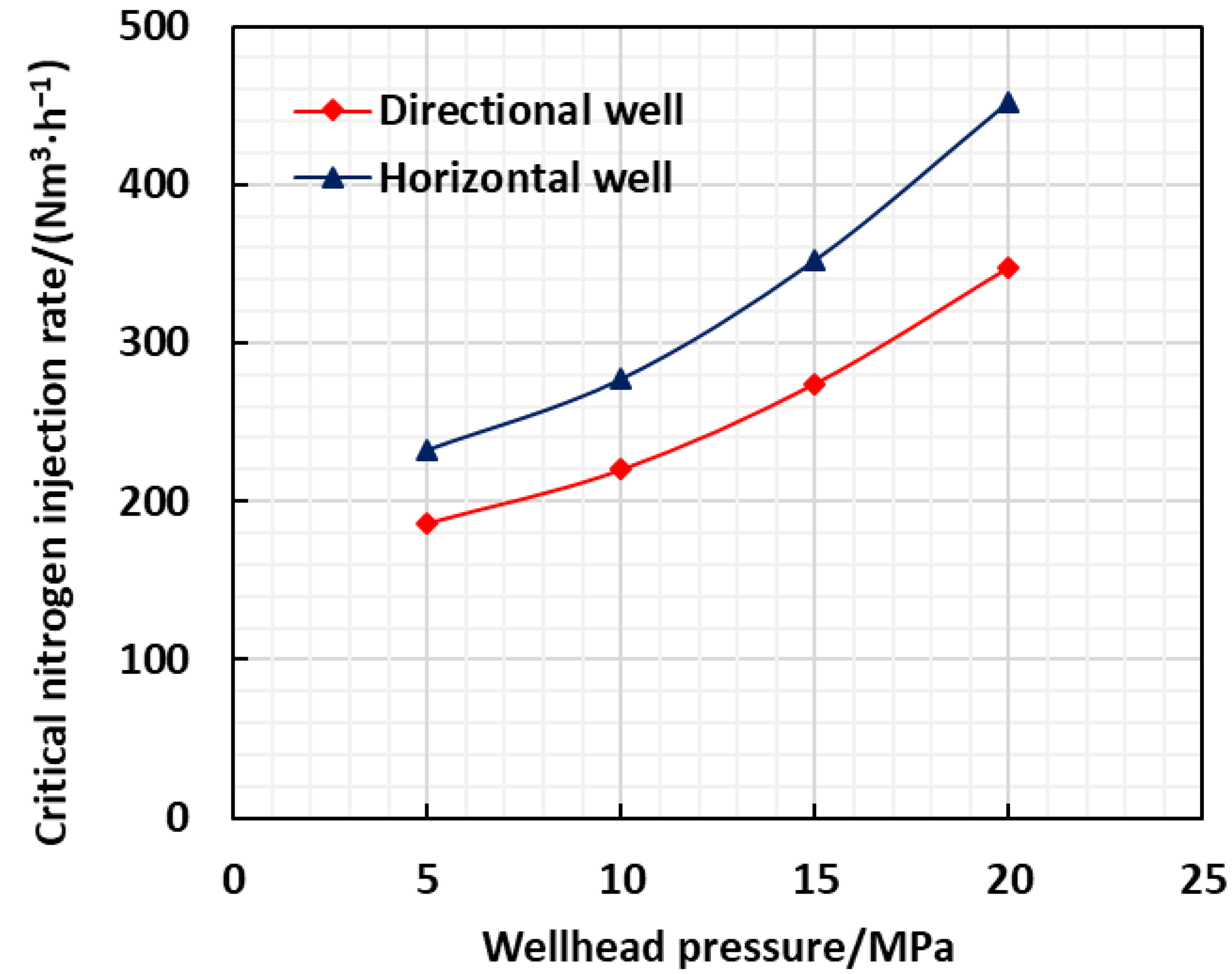
4.1. Influence of Wellhead Steam Injection Parameters

Reservoir parameters mainly include reservoir pressure, steam absorption capacity and reservoir burial depth, which directly affect the wellhead pressure of steam and the length of well completion insulation pipe. The influence of different wellhead pressure and insulation pipe length on the critical nitrogen injection rate was simulated and studied based on the influence of reservoir parameters for directional wells and horizontal wells. The simulation results are shown in Figure 2.
It can be seen from Figure 2 that the critical nitrogen injection displacement required will increase at the rate of nearly quadratic function for both the directional wells and horizontal wells with the increase of steam injection pressure. The main causes are: the higher the steam pressure at the outlet of the insulation pipe, the higher the steam density, and the higher the steam mass per unit volume. Then, the greater the momentum of the steam returning under the same steam injection displacement. Therefore, the critical nitrogen displacement required for casing pipe annulus insulation is also larger. Because of a larger annular space between the insulation pipe and casing in the horizontal well, the annulus thermal resistance is greater when nitrogen is continuously injected into the annulus with a certain displacement. In this case, the annular insulation effect of horizontal well is better than that of directional well. In this case, higher steam dryness can be obtained at the bottom of the horizontal well, and the volume of upward returning steam increases, so the convective heat transfer capacity of steam and nitrogen increases. Therefore, the critical nitrogen injection displacement required by the annulus is also larger.
The injected steam parameters mainly include steam injection displacement and steam dryness. For directional wells and horizontal wells, simulation research on the influence of different steam injection displacement and steam dryness on the critical nitrogen injection displacement was carried out. The simulation results are shown in Figure 3 and Figure 4.
It can be seen from Figure 3 and Figure 4 that with the increase of steam injection displacement and steam dryness, the critical nitrogen injection displacement required for both well types increases rapidly. The reason is that with the increase of steam injection displacement, the heat loss along the steam path decreases, and the dryness and displacement of the upstream steam increase, so the heat exchange capacity and momentum of the upstream steam increase, and the critical nitrogen displacement required to be supplemented in the annulus also increases. With the increase of steam dryness, the volume of upward returning steam increases, and gas has stronger convection heat transfer capacity than liquid, so the critical nitrogen displacement required in the annulus also increases. Similarly, under the same steam injection parameters, the critical nitrogen displacement of horizontal wells is slightly greater than that of directional wells.

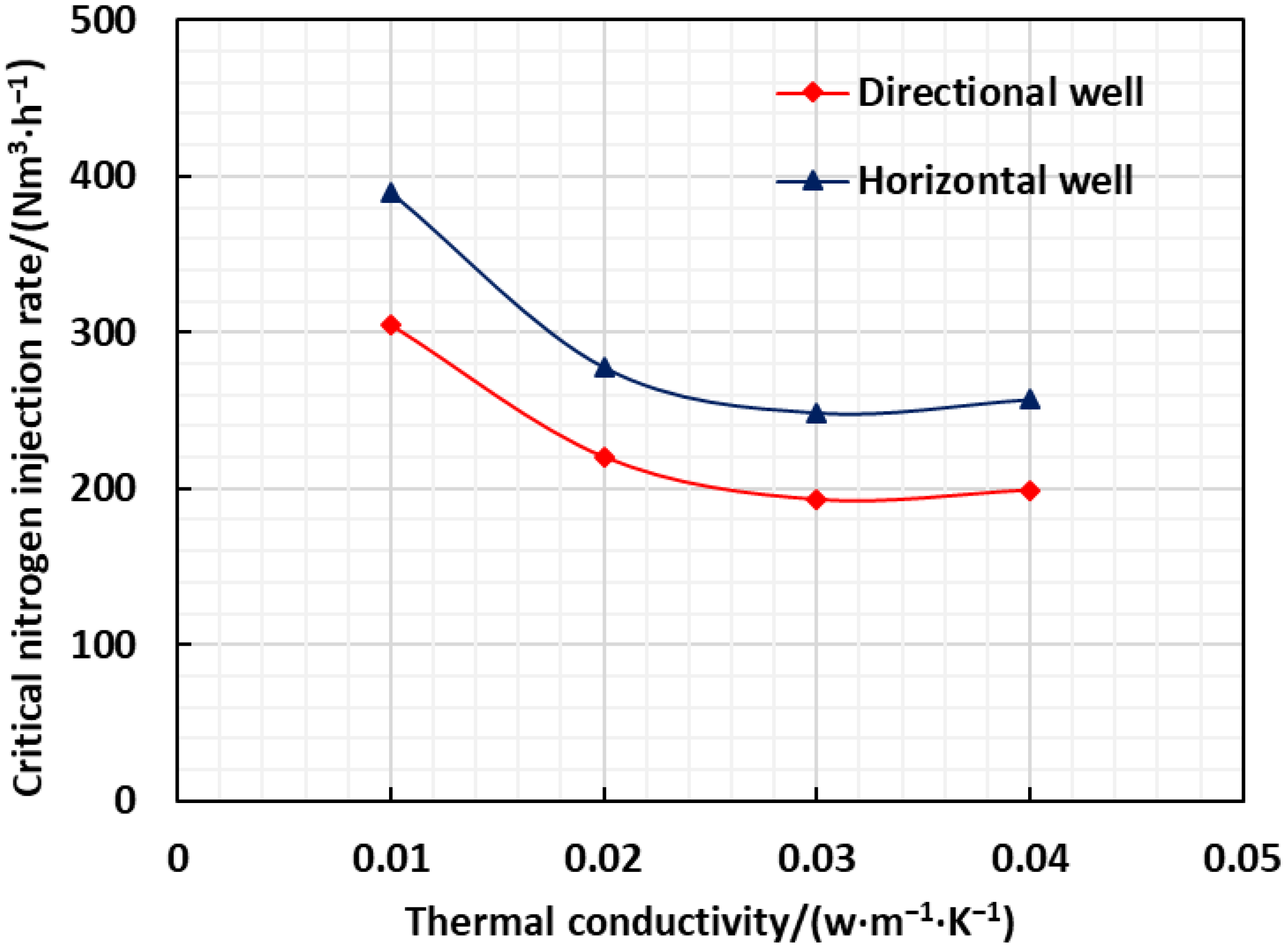
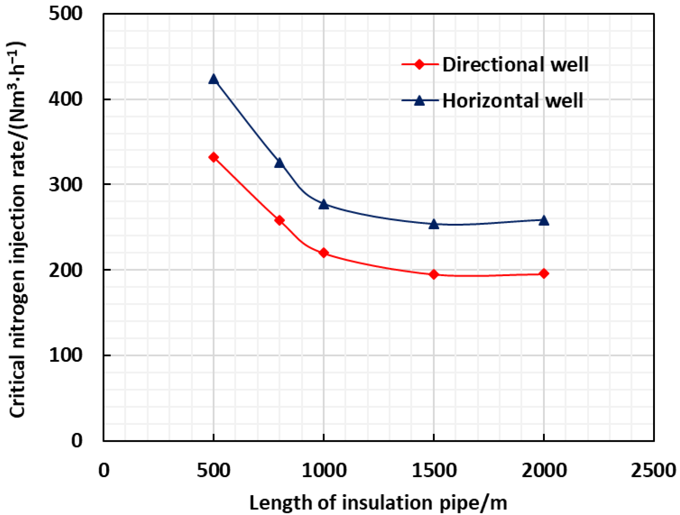
4.2. Effect of Thermal Insulation Pipe Performance

For the field application of thermal insulation pipe, the simulation calculation of critical nitrogen injection displacement under different thermal insulation levels of two well types were carried out, and the simulation results are shown in Figure 5.
It can be seen from Figure 5 that the critical nitrogen injection capacity decreases rapidly with the increase of thermal conductivity of the insulation pipe. This is mainly because: the greater the thermal conductivity of the heat insulation pipe, the greater the heat loss along the way of the steam injected into the heat insulation pipe, and the lower the dryness and displacement of the upward return steam. As a result, the heat exchange capacity and momentum of the upward return steam are reduced, and the critical nitrogen displacement required for the annulus is also reduced. Compared with the annulus temperature test data on site, the thermal conductivity of on-site applied insulation pipe is generally about 0.02 W/(m·K). Similarly, under the same thermal conductivity of insulated pipe, the critical nitrogen displacement required by horizontal well is slightly greater than that of directional well.
It can be seen from Figure 6 that the critical nitrogen injection displacement required decreases rapidly for both well types with the increase of the length of the insulation pipe. When the length of insulated pipe is greater than 1000 m, the reduction rate of critical nitrogen injection capacity slows down. This is mainly because with the increase of the well depth, the length of the insulation pipe of the completion string increases, and the steam dryness at the outlet of the insulation pipe decreases. As a result, the volume of steam returned decreases, reducing the convective heat transfer capacity of steam and nitrogen. Therefore, the critical nitrogen displacement required for annulus insulation also decreases. Under the same insulation pipe length, the critical nitrogen displacement required by horizontal wells is slightly larger than that of directional wells.

4.3. Effect of Annulus Sealing

It can be seen from Formula (9) that the critical nitrogen injection displacement is directly related to the annulus sealing diameter. Based on the existing simulation methods, the critical nitrogen injection displacement under different well types and different annular sealing outer diameters is simulated and calculated, and the results are shown in Figure 7.
It can be seen from Figure 7 that the critical nitrogen injection displacement decreases linearly and rapidly with the increase of the outer diameter of the casing annulus, and the reduction rate of directional wells is faster than that of horizontal wells. The reason is that the inner diameter of directional well casing is 159 mm and that of horizontal well casing is 220 mm, so the casing section area (A1 + A2) corresponding to the smaller casing inner diameter is smaller, which is known from the corresponding Formula (9). The critical nitrogen injection displacement decreases rapidly when the outer diameter of the sealing trap space increases. The decrease range of the outer diameter of 150 mm packer for directional wells is 75%, and that of 210 mm packer for horizontal wells is as high as 88%.

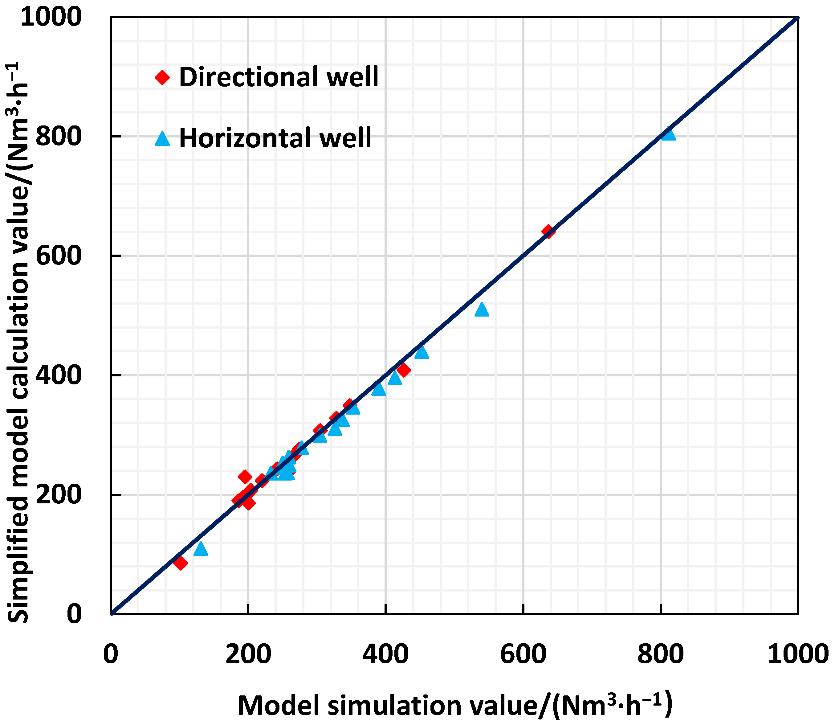
5. Simplified Model of Critical Nitrogen Injection Rate

In order to obtain the optimal value of critical nitrogen injection displacement conveniently, a correlation model is formed based on the simulation results of influencing factors of critical nitrogen injection displacement, as shown in Table 2. The mathematical method of multiple regression analysis is applied to build the numerical model between the critical nitrogen injection rate and the wellhead steam parameters and the insulation pipe parameters on the directional well and the horizontal well.
The simplified model of directional well is:
Q = 160 2 d 2 12 , 604 506.76 + 0.39 P 2 + 0.87 P + 0.94 q 2 + 13.53 q + 0.084 X 2 6.53 X 4.91 × 10 8 L 3 + 2.8 × 10 4 L 2 0.454 L 3.95 × 10 6 α 3 + 5.19 × 10 5 α 2 2.12 × 10 4 α  
The simplified model of horizontal well is:
Q = 220 2 d 2 35 , 404 753.8 + 0.51 P 2 + 0.84 P + 1.26 q 2 + 14.9 q + 0.11 X 2 9.56 X 6.41 × 10 8 L 3 + 3.21 × 10 4 L 2 0.583 L 6.86 × 10 6 α 3 + 7.42 × 10 5 α 2 2.74 × 10 4 α  
where Q is the critical nitrogen injection volume in the annulus, Nm3·h−1; P is the reservoir pressure, MPa; L represents the burial depth of the reservoir, m; X is steam injection dryness, %; q is the steam injection displacement, t·h−1; α is the thermal conductivity of the insulation pipe, w·m−1·K−1; d is the diameter of annulus packer, mm.
The simulation results and the calculation results of the simplified model were compared, as shown in Figure 8. It can be seen from the figure that the prediction error rate of the simplified model for directional wells is 3.24%, and the prediction error rate of the simplified model for horizontal wells is 3.17%. The results show that the simplified model can better predict the critical nitrogen injection rate of steam injection thermal recovery wells under different operating conditions.
It can be seen from the simplified model that with the increase of pressure, steam displacement, and steam dryness, the required critical nitrogen injection displacement increases at the rate of nearly quadratic function. Moreover, with the increase of the length and thermal conductivity of the insulation pipe, the required critical nitrogen injection capacity decreases at a nearly cubic function rate. Therefore, the critical nitrogen injection can be reduced by reducing the annular area of the oil pipe and lowering the string deeply.
The optimization method of annulus nitrogen thermal injection process was applied in three wells in heavy oil reservoir for the in situ modification of shale oil, which was not yet used in the field test. Basic parameters are shown in Table 3. Four parameters of wellbore steam were tested after nitrogen injection, and the measured results are shown in Table 4.
It can be seen from Table 4 that the error rate of bottom hole pressure prediction is 3.32% and the error rate of bottom hole dryness prediction is 1.75% from the comparison between model prediction and actual working conditions. After the optimization of nitrogen insulation injection process, the nitrogen consumption was reduced. The temperature of the annulus decreases under nitrogen insulation, which reduces the heat dissipation rate of steam to the reservoir in the insulation pipe, and the steam dryness at the bottom of the well increases. The average bottom hole dryness of the three wells increased by 3.9%. The optimized nitrogen thermal insulation injection parameters reduce the temperature of the oil casing annulus, reduce the thermal stress concentration of the casing, and effectively slow down the occurrence of casing damage.

6. Conclusions

(1)
The steam parameter prediction model in the insulated pipe string and the nitrogen parameter prediction model in the casing annulus were constructed, which according to the completion structure characteristics of thermal injection wells were based on the basic principles of heat transfer and fluid mechanics. According to the modified model of field test data, the influence of different well types, reservoir parameters, steam parameters, and annulus sealing conditions on the critical nitrogen injection rate was studied.
(2)
Under the different well type conditions, the annulus thermal resistance of horizontal wells is larger than that of directional wells, and the critical nitrogen injection displacement required is higher accordingly. The analysis of influencing factors shows that with the increase of pressure, steam displacement, and steam dryness, the required critical nitrogen injection displacement increases at a quadratic function rate.
(3)
With the increase of the length and thermal conductivity of the insulated pipe, the required critical nitrogen injection rate decreases cubically. However, with the increase of annulus sealing, the required critical nitrogen injection displacement decreases linearly. The research results are of great significance for improving steam quality and string life in thermal injection wells.

Author Contributions

Data curation, C.K.; Methodology, X.Y.; Resources, J.H.; Writing—original draft, S.T.; Writing—review & editing, X.C. All authors have read and agreed to the published version of the manuscript.

Funding

The authors gratefully acknowledge the financial support of the National Science Foundation of China (Grant No. 52004259).

Conflicts of Interest

The authors declare no conflict of interest.

References

  1. Han, X.; Zhong, L.; Liu, Y.; Wang, Q.; Chen, C.; Wu, X. Study and Optimization of the First Horizontal Well Steam flooding Pilot for Offshore Oilfield. In Proceedings of the Offshore Technology Conference, Houston, TX, USA, 4–7 May 2020. [Google Scholar]
  2. Vargo, R.F.; Payne, M.; Faul, R.; LeBlanc, J.; Griffith, J.E. Practical and Successful Prevention of Annular Pressure Buildup on the Marlin Project. Spe Drill. Complet. 2003, 18, 228–234. [Google Scholar] [CrossRef]
  3. Zou, J.; Han, X.; Liu, Y.; Wang, Q.; Zhang, H.; Liu, H.; Wang, H.; Han, C. Research and Application of the Optical Fiber Technology for Real-time Temperature Test of Offshore Thermal Wells. In Proceedings of the Abu Dhabi International Petroleum Exhibition & Conference, Abu Dhabi, United Arab Emirates, 11–14 November 2019. [Google Scholar]
  4. Xu, A.; Mu, L.; Fan, Z.; Zhao, L. New findings on heatloss of superheated steam transmitted along the wellbore and heating enhancement in heavy oil reservoirs. In Proceedings of the IPTC 2013: International Petroleum Technology Conference, Beijing, China, 26–28 March 2013. [Google Scholar]
  5. Xu, A.; Mu, L.; Fan, Z.; Zhao, L.; Bo, B. Mechanism of heavy oil recovery by cyclic superheated steam stimulation. J. Petro. Sci. Eng. 2013, 111, 197–207. [Google Scholar] [CrossRef]
  6. Zheng, S.; Li, W.; Cao, C.; Wang, C. Prediction of the wellhead uplift caused by HT–HP oil and gas production in deep-water wells. Energy Rep. 2021, 7, 740–749. [Google Scholar] [CrossRef]
  7. Zheng, S.; Zhang, C. Influence of Cement Return Height on the Wellhead Uplift in Deep-Water High-Pressure–High-Temperature Wells. ACS Omega 2021, 6, 2990–2998. [Google Scholar] [CrossRef] [PubMed]
  8. Hu, Y.I.N.; Menghan, S.I.; Qian, L.I.; Hongwei, J.A.N.G.; Liming, D.A.I. Mechanism and prevention method of drill string uplift during shut-in after overflow in an ultra-deep well. Pet. Explor. Dev. 2018, 45, 1139–1145. [Google Scholar]
  9. Kaldal, G.S.; Jónsson, M.Þ.; Pálsson, H.; Karlsdottir, S.N. Using Probabilistic Analysis with Finite Element Modeling of High Temperature Geothermal Well Casings. In Proceedings of the Sims Conference, Bergen, Norway, 16–18 October 2013. [Google Scholar]
  10. Kaldal, G.S.; Jonsson, M.T.; Palsson, H.; Karlsdottir, S.N. Structural modeling of the casings in the IDDP-1 well: Load history analysis. Geothermics 2016, 62, 1–11. [Google Scholar] [CrossRef]
  11. Case, R.; Mahajanam, S.; Dunn, J.; Joosten, M.; Achour, M.; Marchebois, H.; Bonis, M. Evaluation of corrosivity of produced fluids during SAGD operations. In Proceedings of the Nace International Corrosion Conference, San Antonio, TX, USA, 9–13 March 2014. [Google Scholar]
  12. Wen, X.; Bai, P.; Luo, B.; Zheng, S.; Chen, C. Review of recent progress in the study of corrosion products of steels in a hydrogen sulphide environment. Corros. Sci. 2018, 139, 124–140. [Google Scholar] [CrossRef]
  13. Valbuena, E.; Bashbush, J.L.; Rincon, A.C. Energy Balance in Steam Injection Projects Integrating Surface-Reservoir Systems. In Proceedings of the SPE Latin American and Caribbean Petroleum Engineering Conference, Cartagena, Colombia, 31 May–3 June 2009. [Google Scholar]
  14. Teodoriu, C.; Falcone, G. Labyrinth Packer Lowers the Costs for Steam Injections Wells: Theoretical and Experimental Results. In Proceedings of the SPE/DOE Improved Oil Recovery Symposium, Tulsa, OK, USA, 3–5 April 2008. [Google Scholar]
  15. Sun, F.; Yao, Y.; Li, X.; Tian, J.; Zhu, G.; Chen, Z. The flow and heat transfer characteristics of superheated steam in concentric dual-tubing wells. Int. J. Heat Mass Transf. 2017, 115 Pt B, 1099–1108. [Google Scholar] [CrossRef]
  16. Cao, R.; Gu, H. A comprehensive mathematical model for predicting thermophysical properties of superheated steamin horizontal injection wells considering phase change. In Proceedings of the SPE Latin American and Caribbean Petroleum Engineering Conference, Quito, Ecuador, 18–20 November 2015. [Google Scholar]
  17. Zhang, B.; Guan, Z.; Wang, Q.; Xuan, L.; Liu, Y.; Sheng, Y. Appropriate Completion To Prevent Potential Damage of Annular Pressure Buildup in Deepwater Wells. In Proceedings of the IADC/SPE Asia Pacific Drilling Technology Conference, Singapore, 22–24 August 2016. [Google Scholar]
  18. Ju, N. A Calculation Model for Steam Property Variation Along Wellbore Trajectory in SAGD Process. In Proceedings of the SPE Latin American and Caribbean Petroleum Engineering Conference, Lima, Peru, 19–20 October 2016. [Google Scholar]
  19. Gu, H.; Cheng, L.; Huang, S.; Zhang, H.; Lin, M.; Hu, C. A New Semi-analytical Model for Predicting Steam Pressure and Temperature in Annuli. In Proceedings of the SPE Latin American and Caribbean Petroleum Engineering Conference, Maracaibo, Venezuela, 21–23 May 2014. [Google Scholar]
  20. Sagar, R.; Doty, D.R.; Schmidt, Z. Predicting Temperature Profiles in a Flowing Well. SPE Reserv. Eng. Novemb. 1991, 6, 441–448. [Google Scholar] [CrossRef]
  21. Alves, I.N.; Alhanatl, F.J.S.; Shoham, O. A Unified Model for Predicting Flowing Temperature Distribution in Wellbores and Pipelines. SPE Prod. Eng. Novemb. 1992, 7, 363–367. [Google Scholar] [CrossRef]
  22. Hasan, A.R.; Kabir, C.S. A Basic Approach to Wellbore Two-phase Flow Modeling. Paper SPE 109868. In Proceedings of the SPE Annual Technical Conference and Exhibition, Anaheim, CA, USA, 11–14 November 2007. [Google Scholar]
  23. Ramey, H.J. Wellbore Heat Transmission. J. Pet. Technol. 1962, 14, 427–435. [Google Scholar] [CrossRef]
  24. Satter, A. Heat Losses During Flow of Steam Down a Wellbore. J. Pet. Technol. 1965, 17, 845–851. [Google Scholar] [CrossRef]
  25. Beggs, D.H.; Brill, J.P. A Study of Two-Phase Flow in Inclined Pipes. J. Pet. Technol. 1973, 25, 607–617. [Google Scholar] [CrossRef]
  26. Kretzschmar, H.J. Mollier h-s Diagram for Water and Steam: Calculated from the IAPWS Industrial Formulation 1997 for the Thermodynamic Properties of Water and Steam IAPWS-IF97, 2nd ed.; Springer: Berlin/Heidelberg, Germany, 2008; ISBN 10:3642033210. [Google Scholar]
  27. Hussein, I.B.; Owen, I.; Amini, A.M. Energy metering system for high quality saturated steam. Flow Meas. Instrum. 1992, 3, 235–240. [Google Scholar] [CrossRef]
  28. Aziz, K. Calculation of Bottom-Hole Pressure in Gas Wells. J. Pet. Technol. 1967, 19, 897–899. [Google Scholar] [CrossRef]
Figure 1. Mixing modes of nitrogen and steam under different nitrogen injection rates. Note: A represents the heat insulation oil pipe, B represents the sleeve, and the red area between A-A represents the injection of steam into the heat insulation pipe. The blue area in A-B indicates that nitrogen is injected into the oil jacket annulus. B-B indicates the cement sheath between the first and second split casings. (a) the nitrogen injection displacement is too large; (b) the nitrogen injection displacement is too small; (c) the nitrogen injection displacement is reasonable.
Energies 15 08034 g001
Figure 2. Relationship between wellhead pressure and critical nitrogen injection displacement.
Energies 15 08034 g002
Figure 3. Relationship between steam injection displacement and critical nitrogen injection displacement.
Energies 15 08034 g003
Figure 4. Relationship between steam quality and critical nitrogen injection displacement.
Energies 15 08034 g004
Figure 5. Relationship between thermal conductivity of heat insulation pipe and critical nitrogen injection displacement.
Energies 15 08034 g005
Figure 6. Relationship between heat insulation pipe length and critical nitrogen injection displacement.
Energies 15 08034 g006
Figure 7. Relationship between annular packing outer diameter and critical nitrogen injection displacement.
Energies 15 08034 g007
Figure 8. Comparison between the simulated values of the model and the calculated values of the simplified model.
Energies 15 08034 g008
Table 1. Simulation scheme of influencing factors of critical nitrogen injection displacement.
Influence FactorsDirectional WellHorizontal Well
Reservoir parametersPressure/MPa5–205–20
Depth/m500–2000500–2000
Steam parametersDisplacement/(t·h−1)5–205–20
Dryness/%50–8050–80
Insulation pipe parametersThermal conductivity/(w·m−1·K−1)0.01–0.100.01–0.10
Table 2. Impact model of different influencing factors on critical nitrogen injection rate.
Influence FactorsWell TypesFitting Formula
Wellhead steam parametersPressure/MPaDirectional wellQ = 0.3959 P2 + 0.8807 P + 171.81R2 = 1
Horizontal wellQ = 0.551 P2 + 0.8866 P + 214.36R2 = 1
Displacement, t/hDirectional wellQ = 0.92 q2 + 13.244 q + 8.06R2 = 0.9979
Horizontal wellQ = 1.2512 q2 + 14.797 q + 20.43R2 = 0.9979
Dryness/%Directional wellQ = 0.0874 X2 − 6.8416 X + 316.91R2 = 0.9994
Horizontal wellQ = 0.1223 X2 − 10.368 X + 461R2 = 0.9992
Insulation pipe parametersThermal conductivity, w/(m·K)Directional wellQ = −4 × 10⁶ α3 + 526,000α2 − 21,459α+ 470.7R2 = 1
Horizontal wellQ = −8 × 10⁶ α3 + 864,750α2 − 31,910α+ 629.9R2 = 1
Length/mDirectional wellQ = −7 × 10⁸ L3 + 0.0004 L2 − 0.6473 L + 574.49R2 = 0.9982
Horizontal wellQ = −107 L3 + 0.0005 L2 − 0.9096 L + 759.06R2 = 0.9977
Table 3. Basic data for on-site implementation of nitrogen insulation.
ParametersValueParametersValue
Formation thermal conductivity/[w·(m·°C)−1]1.73Inner diameter of insulated pipe/m0.076
Thermal conductivity of cement/[w·(m·°C)−1]0.993Outer diameter of inner pipe of heat insulation pipe/m0.0889
Geothermal gradient/[°C·(100 m)−1]3.8Inner diameter of outer pipe of heat insulation pipe/m0.1016
Outer diameter of technical casing/m0.1778Outer diameter of outer pipe of heat insulation pipe/m0.1143
Inside diameter of technical casing/m0.159Outer diameter of packer/m0.155
Depth of heat insulation pipe of Shu 1-X well/m852.7Gas injection velocity/(t·h−1)5
Depth of heat insulation pipe of Shu 1-Y well/m860.9Steam injection time/d15
Depth of heat insulation pipe of Shu 1-Z well/m869.6Nitrogen concentration/%99.9
Wellhead steam dryness/%65Nitrogen velocity/(Nm3/h)35
Table 4. Comparison of wellbore steam dryness before and after optimization of nitrogen insulation process.
Well No.Before optimizationAfter optimization
Injection Pressure/
MPa
Bottom Hole Pressure/
MPa
Bottom Hole Dryness/
%
Injection Pressure/
MPa
Bottom Hole Pressure Prediction/MPaMeasured Bottom Hole Pressure/MPaBottom Hole Dryness Prediction/%Measurement of Bottom Hole Dryness/%
Shu1-X7.584.1347.37.974.724.6049.550.5
Shu1-Y6.154.2755.27.035.355.1358.159.3
Shu1-Z5.843.5258.36.134.224.0962.963.7
Publisher’s Note: MDPI stays neutral with regard to jurisdictional claims in published maps and institutional affiliations.

