Abstract
The Francis hydro-turbine is a typical nonlinear system with coupled hydraulic, mechanical, and electrical subsystems. It is difficult to understand the reasons for its operational failures, since the main cause of failures is due to the complex interaction of the three subsystems. This paper presents an improved dynamic model of the Francis hydro-turbine. This study involves the development of a nonlinear dynamic model of a hydraulic unit, given start-up and emergency processes, and the consideration of the effect of water hammer during transients. To accomplish the objectives set, existing models used to model hydroelectric units are analyzed and a mathematical model is proposed, which takes into account the dynamics during abrupt changes in the conditions. Based on these mathematical models, a computer model was developed, and numerical simulation was carried out with an assessment of the results obtained. The mathematical model built was verified on an experimental model. As a result, a model of a hydraulic unit was produced, which factors in the main hydraulic processes in the hydro-turbine.
1. Introduction
Currently, stochastic renewable (wind and solar) energy sources are rapidly developing in the world, and hydropower plays a key role in ensuring the security and stability of the energy system with a high share of renewable energy sources. Global hydropower continues to increase with relatively higher rates of total installed capacity in the last 10 years alone. This expansion means that it is becoming increasingly more important to investigate various hydropower plants (HPPs). A significant number of studies examine the dynamics of the Francis turbine. In particular, the work by E.Vagnonia, et al. [1] focuses on the study of the dynamics of the Francis turbine under the action of a voltage regulator. The paper presents the results of the studies on the behavior of the generator operating as a synchronous compensator, given the pressure fluctuations in the turbine. The study presented in [2] is devoted to the minimization of fluctuations in the rotation speed at the idle start of the turbine and the optimization of starting the unit with the turbine control algorithm based on the theory of fuzzy logic. This approach provides the flexibility of the regulator settings and reduces vibration during unit start-up. Article [3] provides an analysis of the algorithms and their impact on the turbine operating conditions and the effects of disturbances from the load side. Article [4] presents the construction of dynamic models of the turbine and their transfer functions, which affect the quality of the transient process in the case of various auxiliary systems during the hydraulic unit operation, but do not take into account emergency processes in the power system. There are studies focusing on the modeling of power fluctuation that occurs during the start-up of the unit [5]. However, the authors of this work do not provide a condition for the emergency shutdown of the unit. The authors of [6] analyze the dynamics of the HPP pump-turbine in terms of an improvement of the model of the Francis turbine. Article [7] addresses quantitative analysis and identification of the mechanism of influence of hydraulic damping of low-frequency oscillations in power systems. In [8], the authors present the results of the analysis of complex power systems, which have a large number of various energy sources, and the dynamic simulation of their electromechanical transients. Article [9] presents various transfer functions for turbine models used in pumped-storage plants, given the process constraints. The authors of [10] present some simulation models of a hydro-turbine governing system with different water diversion system topologies, which make it possible to calculate the damping of low-frequency oscillations. The focus of [11] is on the analysis of various nonlinear dynamic characteristics of regulation systems, which ensure the stability of the control system. Article [12] performs an analysis of the stability of the hydro-turbine controller, which is the most important stage in the design of the prime mover operating in the power system, since it is essential for the safety of both the power plant and the power system. Given the nonlinearity of the hydro-turbine, a comprehensive analysis of the stability of the hydro-turbine control system was carried out for the cases of frequency control and power control. However, the algorithms of emergency scenarios are not provided. In [13], authors consider a nonlinear modal method, which was introduced to analyze the dynamic modal interactions between the subsystems of the HPP hydraulic unit, and compare the results obtained by different methods to check the feasibility of the method. There are studies of the multi-frequency dynamic characteristics of a hydropower plant under the coupling effect of the power grid and the turbine regulating system with a surge tank [14]. In article [15], the study examines the hydraulic oscillations between two pump-turbines after the water flow rate is reduced to zero for the parallel operation of the two units. The findings indicate that two pump-turbine units have the same oscillation cycle, but their transient processes are significantly different. In [16], the influence of the conduit geometry on the dynamic parameters of the unit is analyzed. The finite element method is used to evaluate the performance of the turbine. Article [17] analyzes the influence of backlash nonlinearity on the stability of island power systems, where the Nyquist stability criterion and the numerical modeling method are used to control hydraulic turbines. Another focus of the study is on the mechanism of the influence of four important hydromechanical time constants on the stability of a nonlinear system of a hydraulic unit. Article [18] considers simplified mathematical models to help in monitoring the vibration of hydro-generators and illustrates this proposal by modeling a hydro-generator with a capacity of 700 MW. In [19], fluctuations between two hydroelectric power plants in a separate power system of China are investigated, where different excitation systems are considered. Article [20] considers quaternary storage hydropower technology as one of the new advanced technologies, which combines a variable speed pumping unit and a conventional hydropower turbine in a four-component configuration, which allows it to have a greater competitive ability to provide fast power support in a future system with a high degree of penetration of renewable energy sources. The above studies do not take into account the transient processes associated with emergency processes during load shedding. There is a study investigating transient processes during fast unloading of the turbine [21]. The findings suggest that the output real power characteristic is highly dependent on the guide vane opening speed in both field and simulation tests, however, the studies consider load shedding without analyzing different load ranges. The development of such a model would make it possible to create a system of automatic diagnostics in real time. The study [22] focuses on the development of turbine models for wider ranges of hydraulic unit start-up. The contribution of this article is that an accurate real-time equivalent circuit model of HPP with error compensation is proposed to resolve the conflict between real-time online simulation and accuracy under various operating conditions. In the future, this can help build a system for the automatic distribution of operating units, taking into account the model implemented by the station [23,24]. Article [25] is devoted to modeling the turbine of pumped-storage plants operating in a wide range of power. The finite element method is applied to simulate the pulsation. Numerical transient simulation can support the operation of hydropower plants and help avoid hazardous operating conditions, thereby indirectly extending plant run time and improving economic effect.
Currently, there is a whole host of works constructing mathematical models to study a wide variety of processes from electromechanical oscillations to the influence of hydrodynamic processes on the behavior of the unit. According to the analysis of the literature, many previous studies use the finite element method and the construction of transfer functions for modeling individual main components of hydroelectric power plants, but the developed models are simplified and cannot simulate some complex transients during the emergency unloading of the turbine. The design of a modern hydroelectric power plant or theoretical research in the field of hydropower are unthinkable without the widespread use of mathematical modeling at all stages of development [26,27,28,29]. Therefore, this paper develops a nonlinear dynamic model of a hydraulic unit, given start-up and emergency processes, and considers the effect of water hammer during transients. To analyze transient processes, a model is implemented in the SimInTech simulation environment, which allows dynamic simulation for a huge number of various technical systems and automatic control devices.
2. Construction of a Mathematical Model
Figure 1 shows a block diagram of a hydroelectric power plant (HPP) [3]. Running water from the upstream enters the spiral chamber after passing through the guide vanes, thus contributing to the rotation of the turbine connected to the generator through the shaft. Hydro-generator speed is maintained by changing the opening angle of the guide vanes, which are regulated by an oil servomotor. The system consists of four main parts: piping system, water turbine, servosystem, and generator. In recent years, linear and nonlinear dynamic models of the main parts have been proposed [3,30], but modeling with these models is carried out in ideal situations or is too simplified.
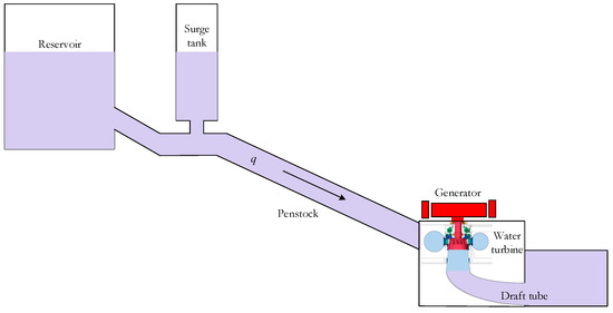
Figure 1.
A general layout scheme of a hydropower plant. An HPP conduit model (Conduit penstock model).
According to the theory of hydrodynamics, the flow equation is as follows:
where the subscripts q and p are the designations of the conduit sections for the upper and lower pools of the HPP, Δx = L is the conduit length, and r and zc are HPP the conduit equation components.
3. The Mathematical Model Development
3.1. Model of a Water Turbine with Elastic Water Hammer
The turbine equation for a small perturbation around the target point is:
Partial derivatives of the turbine torque and flow with respect to the turbine speed have the form [30]:
Transfer function of the turbine and conduit [3] are:
where are Francis turbine performance parameters.
3.2. Generator Model
This paper considers the operation of a hydroelectric power plant for an isolated load. The mathematical model can be represented as follows:
where:
δ is the rotor angle, me is the output electric moment, D is the damper factor, Ta is the generator mechanical time constant, Ef is the field voltage, is the generator voltage, is the positive sequence reactance, is the positive sequence transient impedance, Td is the field winding time constant, id is the positive sequence current, vs. is the network voltage, and Zq is the generator reactance.
4. Francis Turbine Control Dynamics
The main expression, which takes into account the control dynamics of the unit, can be represented by an integrating factor that describes the inertia of the water flow in the turbine conduit [27]:
where q is the turbine flow, h0 is the full head of the hydraulic turbine, h is the turbine inlet head, p.u.; is the water hammer time constant (s) calculated from:
where is conduit length, m; A is the conduit area, m2; g = 9.81 m2/s is the gravitational acceleration, or:
To study the behavior of a hydraulic unit, a simplified mathematical model (Figure 2) is usually used [27]. Its derivation is provided in [31,32]. All formulas are provided for parameters reduced to per units.
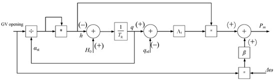
Figure 2.
A simplified model of a hydraulic turbine.
To calculate the flow through the unit, a simplified equation is used for the liquid outflow through a surface area S, which depends on the opening of the guide vane. This study assumes a linear dependence of change in the flow rate on opening. In actuality, the dependence is not linear and depends on the geometry of the guide vane; however, such an assumption will not affect the quality of the transient process.
where a0 is the guide vane opening, p.u.
Figure 3 shows the model according to the block diagram shown in Figure 1 and Figure 2. To verify the correctness of the resulting model, numerical modeling at the initial stage was carried out with the following conditions: Δw = 0.05, qnl = 0.05, H0 = 1, TR = 0.1, β = 1.
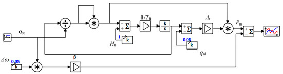
Figure 3.
The proposed model of the hydraulic turbine.
To test the model, the response of the system to the step input that occurs at the time of 10 s was investigated. A graph of the turbine transient process, with a sharp step change in the opening of the guide vane (GV) (αst) from 0.5 to 0.9, is provided in Figure 4. The graph shows a dip at the time of GV opening (t = 10 s), which is explained by a sharp change in the water flow rate in the penstock conduit, causing water hammer. Thus, at the initial moment, most of the flow energy is applied to increase the pressure, and the turbine power drops.
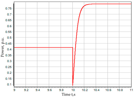
Figure 4.
Change in power for the guide vane opening from 0.5 to 0.9 p.u.
In practice, such a sharp dip does not occur, due to the inertia of the control system. The movement of the guide vanes takes a few seconds but does not happen instantly. The servomotor can be simulated aperiodically by an expression with time constant Ts:
The diagram of a hydro-turbine with an aperiodic inertia element, which takes into account the servomotor, is shown in Figure 5. The result is shown in Figure 6. The power dip caused by the change in setpoint (at the time t = 10 s) is much less compared with the previous result. At the same time, the time of the transient process increased. Such a response of the turbine to a stepped input is more adequate and closer to the behavior of a real-world turbine, in contrast to the transient process shown in Figure 4. All this proves the need to take into account the inertia of the control element, in addition to the inertia of the impeller itself.
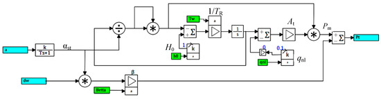
Figure 5.
A hydraulic turbine diagram with the servomotor.
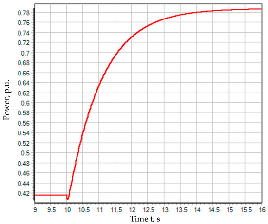
Figure 6.
Transient process with a smooth opening of the guide vane.
5. Comparison of Results with Experimental Data
The modeling results allow the conclusion that the behavior of the model is adequate; however, to make sure of this, it is necessary to compare the results obtained by calculation with real data. To this end, the data obtained in the experiment [33] for the Francis radial–axial turbine are used.
5.1. Simulated Plant
The object of simulation in the work is an experimental stand with a radial–axial turbine, provided by the Norwegian Hydropower Centre for open-source access [34] The stand consists of two tanks simulating the upstream and downstream; the penstock conduit is represented by a pipe closed by a valve. The model turbine diameter is 0.35 m. A magnetic system flow meter is used to measure the water flow. The nominal head of the plant is 12 m. The nominal flow rate at the optimum point is 0.2 m3/s. The nominal power of the hydraulic unit is 24 kW. To measure the water flow parameters, several pressure sensors are placed on the stand: at the turbine inlet (between the guide vanes and the impeller blades), on the turbine blades, and at the turbine outlet (in the suction pipe cone). The sampling frequency of the sensors is 2 KHz. The diagram of this plant is shown in Figure 7.
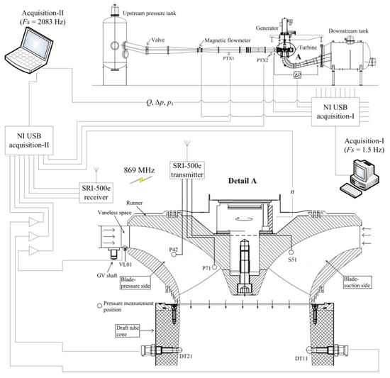
Figure 7.
Experimental stand of a hydro-turbine plant [34].
This experiment involved the investigation of the processes during the turbine acceleration from the minimum opening to the optimal one and the turbine deceleration from the optimal opening angle to the minimum one.
The initial data for the experiment are shown in Table 1.

Table 1.
Limiting parameters of the experiment.
5.2. Braking Process
The study examines the process of braking, in which the opening angle of the guide vane changes from 9.84 to 0.8 degrees. Changing the opening angle of the guide vane is shown in Figure 8.
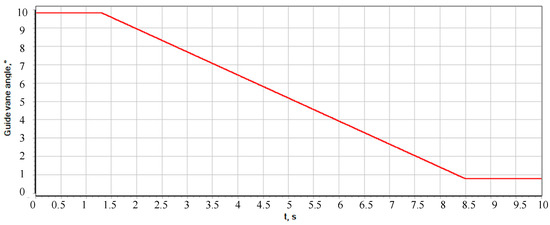
Figure 8.
The opening angle of the GV versus time (α).
The change in the flow through the turbine, in time, causes a head surge. This can be seen from the pressure measured at the turbine inlet in Figure 9. When the guide vane reaches the minimum opening angle, the change in the flow stops and the inlet pressure begins to recover. The difference between the steady-state pressure before and after the opening of the guide vanes is explained by a decrease in the speed losses in the conduit, which are virtually absent at the turbine idling.
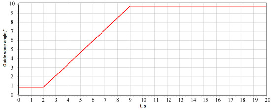
Figure 9.
The GV opening angle versus time (α).
5.3. Acceleration Process
For the case with turbine acceleration, the opening angle changes from 0.8 degrees to 9.84, as shown in Figure 9. The graph of the inlet pressure is shown in Figure 10.
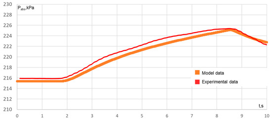
Figure 10.
Transient process in the case of closing the guide vane and the pressure value before the turbine.
To set the opening of the guide vane, the model employs a piecewise linear approximation. The base value of the guide vane opening is taken to be 12.5°. The maximum and minimum opening values are 9.84 and 0.8, respectively. The opening value is fed to the input of the hydro-turbine model; the results are shown in Figure 10 and Figure 11. Closing the guide vane within 6 s leads to an increase in pressure due to a decreasing flow. When the turn of the guide vanes ends, the pressure value reaches its original value. The basic head value is 12.14 m, and the working head is 11.80 m.
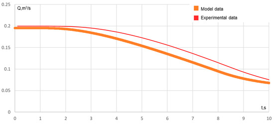
Figure 11.
Transient process in the case of closing the guide vane and the value of the flow through the turbine.
The results of the load increase modeling are shown in Figure 12 and Figure 13. When the guide vane is opened, the flow energy is used to increase the flow rate and the pressure drops. In contrast to the model characteristic, the steady-state value of the head is different for measurements before and after the guide vane opening. The pressure at the turbine inlet decreases with an increase in the flow, which is caused by water speed losses in the conduit.
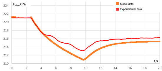
Figure 12.
Transient process in the case of opening the guide vane before opening the optimum point and the value of the pressure before the turbine.
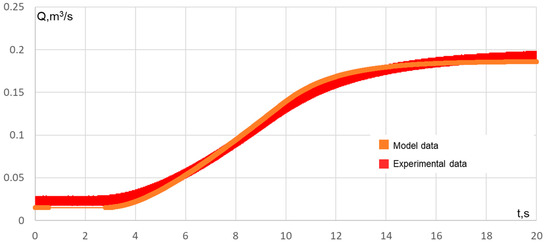
Figure 13.
Transient process for the case of opening the guide vane before opening the optimum point and the value of the flow through the turbine.
Based on the modeling and comparison of the modeling results with empirical data, we can conclude that the behavior of the model is not only adequate, but also corresponds to the behavior of a real-world turbine.
After the successful verification of the mathematical model, we will model a hydro-turbine as part of a hydroelectric unit. The modeling object will be the above-described radial–axial turbine impeller operating on a shaft with a hydro-generator for an isolated load.
The “bidirectional bus” block (which transmits the values of the power on the shaft, the speed setting, and the actual speed) is used to relate the turbine model with the generator model. The internal structure of the “hydro-turbine” block is shown in Figure 14.
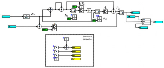
Figure 14.
A diagram of the hydro-turbine block.
The above-described mathematical model is used to build an electrical circuit (Figure 15). The circuit simulates the energy block “hydraulic unit—transformer” operating for the load.
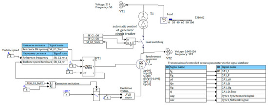
Figure 15.
Model of the block “hydraulic unit—transformer” operating for the isolated load.
To set the current operating conditions of the hydraulic unit and provide feedback, automatic control circuits are used, which, based on an array of input signals, generate output signals according to a given algorithm.
The following conditions are considered:
- Shutdown of the hydraulic unit
- No-load conditions of the hydraulic unit
- No-load conditions of the generator
- Generator normal operating conditions
Switching to another operating condition is performed on an appropriate command. The described algorithm is shown in Figure 16.
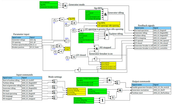
Figure 16.
An algorithm of automatic control of the hydraulic unit operating conditions.
To control the power of the hydraulic turbine and maintain a given speed, it is necessary to use a controller. Therefore, we use a feedback PID controller. The diagram of such a controller is described in [34].
PID controller maintains the speed of the hydraulic turbine (Figure 17), and, in addition to speed control, implements mechanisms for limiting the maximum and minimum opening of the guide vane. The minimum and maximum opening setpoints depend on the operating conditions of the turbine. For example, when the speed rises from 0 to 100%, the opening limit is 40%, which does not allow the controller to force the opening of the guide vane because of a large speed deviation from the setpoint. Such action of the controller would lead to a significant overshoot and an increase in the time necessary to reach a steady-state value [35,36,37].
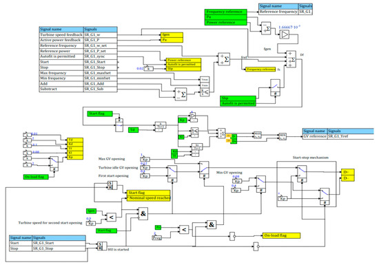
Figure 17.
Model of the speed controller.
6. Analysis of Results
6.1. Turbine and Generator No-Load Operating Conditions
Based on the comparative studies, the mathematical models were verified for various operating conditions of the hydraulic turbine. Relying on the comparative data obtained, we built a model of the hydraulic unit operating for an isolated load. The calculation for a generator with known parameters can be carried out and the previously modeled hydro-turbine can be scaled using known similarity formulas. The similarity equations for hydraulic machines are used to switch from a model turbine to a turbine of a different power [36]:
Thus, a hydraulic unit with an active power of 42 MW, a nominal voltage of 10.5 kV, and a rotation speed of 100 rpm was chosen as an object to be simulated.
First of all, we check the no-load operation of the unit. When the “generator no-load operation” command is given, the unit sequentially switches to the turbine no-load operation mode, and then to the generator no-load operation mode, supplying the field current to the rotor winding. Figure 18 shows the parameters of this transient process. At the first time instant, the guide vane (GV) opens for start-up (40%), then, when approaching the nominal speed, it is closed to the opening of no-load conditions. At the same moment, the excitation of the synchronous machine is turned on and the stator voltage rises to the nominal value (10.5 kV). Rotation speed deviation is less than 2%.
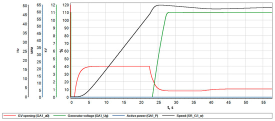
Figure 18.
Parameters of the transient process during the turbine acceleration to idle speed.
6.2. On-Load Operation and Load Increase
Another operating condition to explore is an increase in the load. Figure 19 shows the transient process during the acceleration of the hydraulic unit to the nominal speed under no load, which is followed by the connection of a 12 MW load [38,39,40].
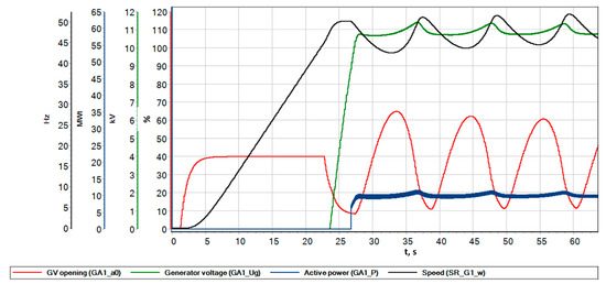
Figure 19.
Parameters of the transient process during the load surge.
When the turbine unit is started and generator reaches the idle speed, the generator breaker is turned on. In this case, a slowly damping oscillatory process occurs with a swing of 12.5 Hz (25%).
In real-world control systems, the controller coefficients are often changed for different operating conditions. Figure 20 presents the frequency response characteristic for the current PID controller (Table 2) and for the desired controller operating under load.
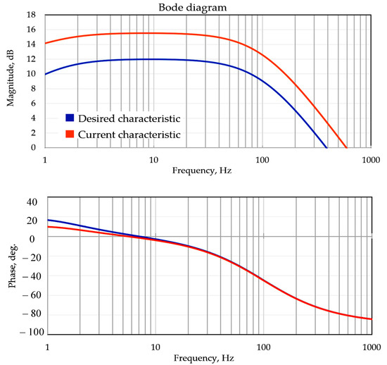
Figure 20.
Logarithmic amplitude and phase–frequency response curves for the current and desired controllers.
Table 2.
Final controller settings.
Analysis of the diagrams indicates that in order to obtain the desired response, it is enough to reduce the proportional coefficient of the PID controller [41,42,43]. Therefore, we made a proportional change in the coefficient of the controller from 4 to 2. The result of this change is shown in Figure 21. After load surge, the frequency dropped to 43 Hz and recovered to the nominal value within 50 s.
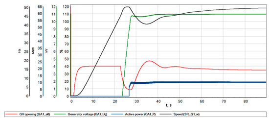
Figure 21.
Parameters of the transient process.
6.3. Emergency Load Shedding
Compared to load surge, load shedding is much more dangerous. To simulate load shedding, we increased the load to the nominal value and when the generator reached the nominal conditions, the load was shed. As soon as the transient process ended and the frequency was nominal, the generator circuit breaker was turned off. The time of tripping corresponds to the simulation time, i.e., 90 s (Figure 22).
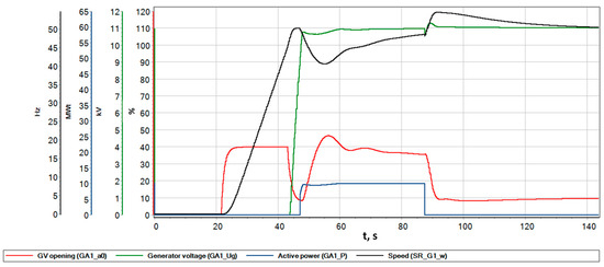
Figure 22.
Parameters of the transient process during emergency load shedding.
When the load dropped to 12 MW, the unit accelerated to a frequency of 57 Hz (114%); at the same moment, the controller operated and closed the guide vane to the minimum opening. It took approximately a minute for the frequency to recover. The controller responded instantly, at the moment of load shedding, by “landing” the guide vane on the lower opening limit, thereby preventing further acceleration of the rotor of the unit.
7. Conclusions
The paper presents a model developed to simulate the electromechanical transient processes of a hydraulic unit operating for an isolated load. With the constructed model, numerical modeling was carried out and the characteristics of transient processes were obtained for various operating conditions of the unit (no-load, load surge, and load shedding). Similar results can be used to study and analyze the operation of existing systems.
The modeling results can be used not only to examine but also to tune the controllers and debug automatic systems used at hydropower plants. Moreover, such real-time simulations can be used to build simulators for the plant personnel to study all the nuances of the process control systems of a hydroelectric unit and its auxiliary equipment.
Author Contributions
Conceptualization, A.A., S.K. and K.S.; methodology, S.K. and A.A.; software, A.A.; validation, P.I., A.A., S.K. and K.S.; formal analysis, A.A. and S.K.; investigation, P.I., A.A., S.K. and K.S.; resources, K.S.; data curation, S.K.; writing—original draft preparation, A.A.; writing—review and editing, P.I., A.A., S.K. and K.S.; visualization, A.A.; supervision, K.S.; project administration, P.I. and K.S.; funding acquisition, P.I. and K.S. All authors have read and agreed to the published version of the manuscript.
Funding
The research was carried out within the state assignment of Ministry of Science and Higher Education of the Russian Federation (project code: FZZS-2020-0039).
Data Availability Statement
Data sharing is not applicable. No new data were created or analyzed in this study. Data sharing is not applicable to this article.
Conflicts of Interest
The authors declare no conflict of interest.
References
- Vagnonia, E.; Valentinb, D.; Avellana, F. Dynamic Behaviour of a Francis Turbine during Voltage Regulation in the Electrical Power System. Available online: https://www.semanticscholar.org/paper/Dynamic-behaviour-of-a-Francis-turbine-during-in-Vagnonia-Valentinb/b13f7e64e0c79538d11552a84bd9e7fbe3f71951 (accessed on 12 May 2022).
- Xu, Y.; Zheng, Y.; Du, Y.; Yang, W.; Peng, X.; Li, C. Adaptive Condition Predictive-Fuzzy PID Optimal Control of Start-up Process for Pumped Storage Unit at Low Head Area. Energy Convers. Manag. 2018, 177, 592–604. [Google Scholar] [CrossRef]
- Chen, Z.; Yuan, X.; Yuan, Y.; Lei, X.; Zhang, B. Parameter Estimation of Fuzzy Sliding Mode Controller for Hydraulic Turbine Regulating System Based on HICA Algorithm. Renew. Energy 2019, 133, 551–565. [Google Scholar] [CrossRef]
- Huang, Y.; Yang, W.; Liao, Y.; Zhao, Z.; Ma, W.; Yang, J.; Yang, J. Improved Transfer Function Method for Flexible Simulation of Hydraulic-Mechanical-Electrical Transient Processes of Hydro-Power Plants. Renew. Energy 2022, 196, 390–404. [Google Scholar] [CrossRef]
- Brezovec, M.; Kuzle, I.; Krpan, M.; Holjevac, N. Improved Dynamic Model of a Bulb Turbine-Generator for Analysing Oscillations Caused by Mechanical Torque Disturbance on a Runner Blade. Int. J. Electr. Power Energy Syst. 2020, 119, 105929. [Google Scholar] [CrossRef]
- Zhang, H.; Chen, D.; Wu, C.; Wang, X.; Lee, J.-M.; Jung, K.-H. Dynamic Modeling and Dynamical Analysis of Pump-Turbines in S-Shaped Regions during Runaway Operation. Energy Convers. Manag. 2017, 138, 375–382. [Google Scholar] [CrossRef]
- Yang, W.; Norrlund, P.; Bladh, J.; Yang, J.; Lundin, U. Hydraulic Damping Mechanism of Low Frequency Oscillations in Power Systems: Quantitative Analysis Using a Nonlinear Model of Hydropower Plants. Appl. Energy 2018, 212, 1138–1152. [Google Scholar] [CrossRef]
- Wang, L.X.; Zheng, J.H.; Li, Z.G.; Jing, Z.X.; Wu, Q.H. Order Reduction Method for High-Order Dynamic Analysis of Heterogeneous Integrated Energy Systems. Appl. Energy 2022, 308, 118265. [Google Scholar] [CrossRef]
- Zhao, Z.; Yang, J.; Chung, C.Y.; Yang, W.; He, X.; Chen, M. Performance Enhancement of Pumped Storage Units for System Frequency Support Based on a Novel Small Signal Model. Energy 2021, 234, 121207. [Google Scholar] [CrossRef]
- Lu, X.; Li, C.; Liu, D.; Zhu, Z.; Tan, X. Influence of Water Diversion System Topologies and Operation Scenarios on the Damping Characteristics of Hydropower Units under Ultra-Low Frequency Oscillations. Energy 2022, 239, 122679. [Google Scholar] [CrossRef]
- Guo, W.; Yang, J. Dynamic Performance Analysis of Hydro-Turbine Governing System Considering Combined Effect of Downstream Surge Tank and Sloping Ceiling Tailrace Tunnel. Renew. Energy 2018, 129, 638–651. [Google Scholar] [CrossRef]
- Liu, D.; Wang, X.; Peng, Y.; Zhang, H.; Xiao, Z.; Han, X.; Malik, O.P. Stability Analysis of Hydropower Units under Full Operating Conditions Considering Turbine Nonlinearity. Renew. Energy 2020, 154, 723–742. [Google Scholar] [CrossRef]
- Xu, B.; Luo, X.; Egusquiza, M.; Ye, W.; Liu, J.; Egusquiza, E.; Chen, D.; Guo, P. Nonlinear Modal Interaction Analysis and Vibration Characteristics of a Francis Hydro-Turbine Generator Unit. Renew. Energy 2021, 168, 854–864. [Google Scholar] [CrossRef]
- Liu, Y.; Guo, W. Multi-Frequency Dynamic Performance of Hydropower Plant under Coupling Effect of Power Grid and Turbine Regulating System with Surge Tank. Renew. Energy 2021, 171, 557–581. [Google Scholar] [CrossRef]
- Hu, J.; Yang, J.; Zeng, W.; Zhao, Z.; Yang, J. Hydraulic Interaction of Two Parallel Pump-Turbines in Constant-Speed Oscillation: Measurement, Simulation, and Sensitivity Analysis. Renew. Energy 2021, 176, 269–279. [Google Scholar] [CrossRef]
- Cao, J.; Tian, H.; Ahn, S.-H.; Duo, W.; Bi, H.; Zhao, L.; Zhao, G.; Gao, H.; Wang, M.; Ma, G.; et al. Fatigue Analysis in Rotor of a Prototype Bulb Turbine Based on Fluid-Structure Interaction. Eng. Fail. Anal. 2022, 132, 105940. [Google Scholar] [CrossRef]
- Liao, Y.; Yang, W.; Zhao, Z.; Li, X.; Ci, X.; Alizadeh Bidgoli, M.; Yang, J. Influence Mechanism of Backlash Nonlinearity on Dynamic Regulation Stability of Hydropower Units. Sustain. Energy Technol. Assess. 2022, 51, 101917. [Google Scholar] [CrossRef]
- Brito Junior, G.C.; Machado, R.D.; Chaves Neto, A. Using Simplified Models to Assist Fault Detection and Diagnosis in Large Hydrogenerators. Int. J. Rotating Mach. 2017, 2017, e9258456. [Google Scholar] [CrossRef]
- Liu, X.; Liu, C.Q. Analysis on Oscillations between Two Generators in a Hydro Power Plant and Development of Math Model for a Compound Excitation System. In Proceedings of the Proceedings. International Conference on Power System Technology, Kunming, China, 13–17 October 2002; Volume 2, pp. 1254–1258. [Google Scholar]
- Dong, Z.; Tan, J.; Muljadi, E.; Nelms, R.M.; St-Hilaire, A.; Pevarnik, M.; Jacobson, M.D. Developing of Quaternary Pumped Storage Hydropower for Dynamic Studies. IEEE Trans. Sustain. Energy 2020, 11, 2870–2878. [Google Scholar] [CrossRef]
- Giosio, D.R.; Henderson, A.; Walker, J.; Brandner, P. Rapid Reserve Generation from a Francis Turbine for System Frequency Control. Energies 2017, 10, 496. [Google Scholar] [CrossRef]
- Zhou, J.; Zhao, Z.; Zhang, C.; Li, C.; Xu, Y. A Real-Time Accurate Model and Its Predictive Fuzzy PID Controller for Pumped Storage Unit via Error Compensation. Energies 2018, 11, 35. [Google Scholar] [CrossRef]
- Liao, S.; Zhao, H.; Li, G.; Liu, B. Short-Term Load Dispatching Method for a Diversion Hydropower Plant with Multiple Turbines in One Tunnel Using a Two-Stage Model. Energies 2019, 12, 1476. [Google Scholar] [CrossRef]
- Duan, C.; Minglu, Z.; Changbing, Z.; Mengjiao, Y.; Cheng, M.; Chunhe, S. Research on Hydraulic–Electric Interference and Optimisation of Multi-Turbine Hydropower System Based on the Dual Control Mode. IET Renew. Power Gener. 2019, 13, 1096–1104. [Google Scholar] [CrossRef]
- Kong, L.; Cao, J.; Li, X.; Zhou, X.; Hu, H.; Wang, T.; Gui, S.; Lai, W.; Zhu, Z.; Wang, Z.; et al. Numerical Analysis on the Hydraulic Thrust and Dynamic Response Characteristics of a Turbine Pump. Energies 2022, 15, 1580. [Google Scholar] [CrossRef]
- Zhao, J.; Wang, L.; Liu, D.; Wang, J.; Zhao, Y.; Liu, T.; Wang, H. Dynamic Model of Kaplan Turbine Regulating System Suitable for Power System Analysis. Math. Probl. Eng. 2015, 2015, e294523. [Google Scholar] [CrossRef]
- Nanaware, R.A.; Sawant, S.R.; Jadhav, B.T. Modeling of Hydraulic Turbine and Governor for Dynamic Studies of HPP. In Proceedings of the IJCA Proceedings on International Conference on Recent Trends in Information Technology and Computer Science 2012 ICRTITCS 2012, Florence, Italy, 10–14 September 2012pp. 6–11. [Google Scholar]
- Guo, P.; Zhang, H.; Gou, D. Dynamic Characteristics of a Hydro-Turbine Governing System Considering Draft Tube Pressure Pulsation. IET Renew. Power Gener. 2020, 14, 1210–1218. [Google Scholar] [CrossRef]
- Choo, Y.C.; Muttaqi, K.M.; Negnevitsky, M. Modelling of Hydraulic Governor-Turbine for Control Stabilisation. ANZIAM J. 2007, 49, C681–C698. [Google Scholar] [CrossRef]
- Yuan, X.; Chen, Z.; Yuan, Y.; Huang, Y. Design of Fuzzy Sliding Mode Controller for Hydraulic Turbine Regulating System via Input State Feedback Linearization Method. Energy 2015, 93, 173–187. [Google Scholar] [CrossRef]
- Mover, W.G.P.; Supply, E. Hydraulic Turbine and Turbine Control Models for System Dynamic Studies. IEEE Trans. Power Syst. 1992, 7, 167–179. [Google Scholar] [CrossRef]
- De Jaeger, E.; Janssens, N.; Malfliet, B.; Van De Meulebroeke, F. Hydro Turbine Model for System Dynamic Studies. IEEE Trans. Power Syst. 1994, 9, 1709–1715. [Google Scholar] [CrossRef]
- Trivedi, C.; Gandhi, B.; Michel, C.J. Effect of Transients on Francis Turbine Runner Life: A Review. J. Hydraul. Res. 2013, 51, 121–132. [Google Scholar] [CrossRef]
- NTNU and LTU Francis-99 Workshop. Available online: https://www.ntnu.edu/nvks/f99-test-case1 (accessed on 13 June 2022).
- Dynamic Models for Turbine-Governors in Power System Studies. Available online: https://resourcecenter.ieee-pes.org/publications/technical-reports/PESTR1.html (accessed on 5 August 2022).
- Bao, H.; Yang, J.; Fu, L. Study on Nonlinear Dynamical Model and Control Strategy of Transient Process in Hydropower Station with Francis Turbine. In Proceedings of the 2009 Asia-Pacific Power and Energy Engineering Conference, Wuhan, China, 27–31 March 2009. [Google Scholar] [CrossRef]
- Suslov, K.; Shushpanov, I.; Buryanina, N.; Ilyushin, P. Flexible Power Distribution Networks: New Opportunities and Applications. In Proceedings of the 9th International Conference on Smart Cities and Green ICT Systems (SMARTGREENS 2020), Online, 2–4 May 2020; pp. 57–64. [Google Scholar]
- Karamov, D.N.; Ilyushin, P.V.; Suslov, K.V. Electrification of Rural Remote Areas Using Renewable Energy Sources: Literature Review. Energies 2022, 15, 5881. [Google Scholar] [CrossRef]
- Rylov, A.; Ilyushin, P.; Kulikov, A.; Suslov, K. Testing Photovoltaic Power Plants for Participation in General Primary Frequency Control under Various Topology and Operating Conditions. Energies 2021, 14, 5179. [Google Scholar] [CrossRef]
- Ilyushin, P. Emergency and Post-Emergency Control in the Formation of Micro-Grids. In E3S Web Conferences; EDP Sciences: Les Ulis, France, 2017; Volume 25, p. 02002. [Google Scholar] [CrossRef]
- Ilyushin, P.V.; Shepovalova, O.V.; Filippov, S.P.; Nekrasov, A.A. Calculating the Sequence of Stationary Modes in Power Distribution Networks of Russia for Wide-Scale Integration of Renewable Energy Based Installations. Energy Rep. 2021, 7, 308–327. [Google Scholar] [CrossRef]
- Lavrik, A.; Zhukovskiy, Y.; Tcvetkov, P. Optimizing the Size of Autonomous Hybrid Microgrids with Regard to Load Shifting. Energies 2021, 14, 5059. [Google Scholar] [CrossRef]
- Zhukovskiy, Y.; Tsvetkov, P.; Buldysko, A.; Malkova, Y.; Stoianova, A.; Koshenkova, A. Scenario Modeling of Sustainable Development of Energy Supply in the Arctic. Resources 2021, 10, 124. [Google Scholar] [CrossRef]


Publisher’s Note: MDPI stays neutral with regard to jurisdictional claims in published maps and institutional affiliations. |
© 2022 by the authors. Licensee MDPI, Basel, Switzerland. This article is an open access article distributed under the terms and conditions of the Creative Commons Attribution (CC BY) license (https://creativecommons.org/licenses/by/4.0/).