Abstract
A novel hammer-impact-driven power generator that uses a buzzer-type piezoelectric energy converter (BPEC) for wind-power-generator applications was designed, and the dynamic motions and output characteristics were analyzed. As the active material, Sm0.025-Pb0.9625[(Mg1/3Nb2/3)0.71Ti0.29]O3 (Sm-PMN-PT)ceramic was used; this material has a high piezoelectric charge constant of 1100 pC/N and an electromechanical coupling factor of 58%. A rotational impeller triggered an impact between one end of the bar-type hammer, and, thereby, impact energy transferred to the BPECs. The manufactured power generator was tested from 50 RPM to 250 RPM, using the handmade evaluation system; it was able to operate with small impact force and greatly improved output performance as rotation speed increased. The maximum output of the generator was 10.4 W at a load resistance of 500 Ω and rotation speed of 250 RPM. For improvement of the output characteristics, the generators were arranged such that they could operate simultaneously. Moreover, the proposed model was applied to a Savonius–Darrieus turbine, and the output performance was evaluated at various wind conditions in a wind tunnel.
1. Introduction
Power-generation systems based on fossil fuels have problems of resource depletion and environmental pollution. To overcome these problems, various energy-harvesting technologies using reusable energy sources such as solar [1], thermal [2], and vibration energy [3] have been studied. Among them, power generation using vibration energy has usually been demonstrated by specifically devised piezoelectric cantilever structures, which are structurally optimized in harmony with ambient vibration. In addition, the piezoelectric ceramic material is required to show high performance power generation. In general, soft-type piezoelectric ceramics with high piezoelectric charge constant (d33), determined on the basis of their figure of merit (d × g) of piezoelectric energy conversion [4,5], have been utilized for piezoelectric energy harvesting. A typical piezoelectric material with good piezoelectric properties has a lead-based composition, such as lead zirconate titanate (PZT) [6]. Many researchers have tried to improve the piezoelectric properties by changing the composition of lead-based piezoelectric ceramics, resulting in new materials such as PZT-Pb(Zn1/3/Nb2/3)O3 [7,8], PZT-Pb(Ni1/3Nb2/3)O3 [9,10], and PZT-Pb(Yb1/2N1/2)O3 [11,12]. Recently, based on an effect of local structural heterogeneity, a rare-earth-element-substituted piezoelectric relaxor-PbTiO3 ceramic with morphotropic phase boundary (MPB) composition achieved excellent performance [13,14,15]. The improvement of d33 was particularly clear when Sm ions were substituted for A-sites in the ABO3-type perovskite structure [16,17].
In general, to achieve a superior piezoelectric energy harvester for wind-power generation, an efficient piezoelectric structure for large energy conversion and good piezoelectric material are important, along with a low loss electrical circuit. In the research field of wind-energy harvesters that use piezoelectric energy conversion, a variety of piezoelectric converter structures, such as flutters [18,19], bluff bodies [20,21], airfoils [22,23], etc. (see [24,25]), have been introduced and have shown efficient power output performance for practical wind-power-generator applications. These are generally regarded as potential energy-converter structures for wind-energy-harvesting technology, considering the dynamic fluid mechanism of wind: it is hard to predict wind direction and magnitude in the time and space domains. Nevertheless, flexible piezoelectric converters for wind-power generation seem less attractive for practical energy device applications due to their inferior level (~mW) of power output, which is converted from wind energy.
In the case of using a turbine, a high output performance can be obtained by using strong kinetic energy. Paulo e Silva et al. presented a wind turbine that used piezoelectric transducers for low power (mW) devices that produced a maximum power of 3.78 mW [26]. Kan et al. proposed turbine-based piezoelectric wind-energy harvesters that use an axially retractable bracket-shaped piezoelectric vibrator excited by magnetic force that produced a maximum power of 2 mW [27]. Akbari et al. proposed the piezomagnetic cantilever beam energy harvester connected to the Savonius vertical axis wind turbine that produced the maximum power of 0.482 mW [28]. In our lab, we have also conducted research on small-scale wind turbines and piezoelectric-wind-power generators with magneto-piezo-elastic structures [29,30]. Recently, a study reported a maximum output of 2.6 W by attaching a piezoelectric cantilever to the bottom of a turbine and generating electricity by using the load generated during the rotation [31]. However, most recent studies have been of fairly small size; in this study, a piezoelectric power generator was applied to a larger-scale wind turbine to obtain large output.
In addition, piezoelectric elements of various structures have been applied to piezoelectric-energy-generating systems. Typical structures of piezoelectric elements include piezoelectric cantilevers and buzzers. The piezoelectric cantilever has a structure in which a piezoelectric film is attached to a metal plate and one end is fixed. Due to its structural characteristics, it operates at a specific vibration frequency. The piezoelectric buzzer, composed of a piezoelectric ceramic layer attached to a metallic disc with a larger diameter, has been in constant use for a long time because of its simple structure and mechanical endurance. Regardless, its usage in piezoelectric-energy-device applications has been extremely limited. Therefore, in this work, a piezoelectric buzzer is considered as an attractive potential energy-converting structure for wind-power generation.
In this study, a novel hammer-impact-driven power generator by using buzzer-type piezoelectric energy converter (BPEC) for wind-power-generator applications was designed and dynamic motions and output electrical characteristics were studied under various conditions. For the BPEC, Sm-PMN-29PT thick film ceramic was used as active material. The hammer-impact-driven power generator was designed such that it can respond to various wind-speed environments, and the dynamic motions of the generator were analyzed at various rotation speeds. The output performance of the generator, which was applied to a wind-power generator with a hybrid Savonius–Darrieus turbine, was evaluated under various conditions and improved the output performance by using a generator array.
2. Experimental Procedures
The active material used for piezoelectric energy conversion in this work is Sm0.025-Pb0.9625[(Mg1/3Nb2/3)0.71Ti0.29]O3 (Sm-PMN-29PT) ceramic [17], which was fabricated by a conventional solid-state reaction. The dielectric and piezoelectric properties of the Sm-PMN-29PT ceramic, fabricated in disk shape with diameter of 10 mm and thickness of 0.8 mm, are summarized in Table 1. Its piezoelectric charge constants were evaluated by a piezo d33 meter (ZJ-6B, ALPHA Corp., Guangzhou, China); the dielectric properties were determined by using an impedance analyzer (E4990A, Keysight, Colorado Springs, CO, USA). After confirming the electrical characteristics, a buzzer-type piezoelectric energy converter (BPEC) was successfully fabricated for wind-power-generator applications. Its schematic and photo images are shown in Figure 1. A 200 μm–thick brass metallic disc with a diameter of 65 mm was used as a substrate and an Sm-PMN-29PT piezoelectric disk with a diameter of 35 mm and thickness identical to that of the brass disk was used as an active material for piezoelectric energy conversion. To extract electrical output signals, on both sides of the Sm-PMN-29PT piezoelectric disk, approximately 4 μm–thick Ag electrodes were uniformly coated by a conventional screen-printing method. Both the brass disk and the piezoelectric ceramic disk were tightly bonded with a conductive adhesive epoxy. After curing at 65 °C under 0.35 MPa for 20 min in an autoclave (PO1-700-20, PHOS-ENTECH, Busan, Korea), a monolithic BPEC, in which the center points of both disks were on the same axis, was successfully fabricated. Table 2 summarizes the geometries of the BPEC depicted in Figure 1.

Table 1.
Dielectric and piezoelectric properties of Sm-PMN-29PT piezoelectric ceramic.
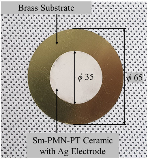
Figure 1.
Photo images of fabricated buzzer-type piezoelectric energy converter.
Table 2.
Summary of components of the buzzer-type piezoelectric energy converter.
A novel power generator, impact-driven by a bar-type hammer, was devised; its detailed structure is described in the following section. The hammer-impact-driven power generator was designed to generate electric power by using two BPECs in slots that are perpendicularly aligned. Geometric details of the designed power generator are provided in the following section. A bar-type plastic hammer with dimensions of 15 mm, 15 mm, and 90 mm in width, height, and length, respectively, was fabricated by using a 3D printer (3DWOX 1, Sindo, Daegu, Korea).
To evaluate the electrical characteristics of the hammer-impact-driven power generator, the output voltage of the open circuit was measured by using an oscilloscope (DSOX 4022A, Keysight, Santa Rosa, CA, USA). Output voltage from the piezoelectric material is derived from the coupled electromechanical dynamic model. Dynamic coupling of the electromechanical systems was defined by Hagood et al. [32]; if the motion of the system is dominated by a single mode, the state-space model can be used to transform this mode to a scalar formulation [33,34]:
where M, C, K, and θ are the mass, damping, stiffness, and coupling matrices of the system, respectively. In addition, w is the displacement, v is the voltage, q is the charge of piezoelectric material, Cp is the capacitance, and f is the applied external force. Therefore, the output voltage is determined by the strength, damping, capacitance, and load resistance of the piezoelectric buzzer, and by the external force. For variables excluding external force, when the same material is used as an internal element, it can be treated as a constant. Therefore, it can be seen from Equations (1) and (2) that the output voltage is determined by an external impact force. Most of the impact force in this system is determined by kinetic energy of the rotating impeller, which can be expressed as Equation (3):
where E is the rotational kinetic energy, I is the rotational momentum, and ω is the angular velocity. Since the rotational momentum of the impeller at the time of striking under various rotational speed conditions is the same, the kinetic energy is determined by the angular velocity of the impeller. Since the magnitude of the kinetic energy is proportional to the square of the speed, an increase in the rotational speed can rapidly increase the impact force.
The generated output power (P) was experimentally determined by using Equation (4):
where Vrms is the measured output root-mean-square voltage under load resistance, R. The performance of the fabricated hammer-impact-driven power generator was systematically assessed by using a handmade evaluation system, which was devised to provide impact of a rotating impeller to the bar-type hammer. The rotation speed of the impeller, which was attached to an electronic motor, was controlled in a maximum range of 500 RPM by a digital controller (S9I180GB-V12, Samyang Moter, Incheon, Korea). The hammer-impact-driven power generator, which was tightly clamped to a large acrylic plate with 600 mm diameter and 15 mm thickness, was connected to a rectifying circuit and a variable resistor to measure the electrical output power characteristics.
To assess its potential for use in a wind-power generator, the power generator, assembled on a large disk plate, was mounted on a commercial hybrid Savonius–Darrieus wind turbine (DS-300, Hienergy, Incheon, Korea). The velocity of wind generated by commercial electric fans (DTV-500CA, Dongkun Ind., Seoul, Korea) was measured with an anemometer (AVM-03, PROVA, Shenzhen, China).
3. Results and Discussion
Figure 2 provides an illustration of the hammer-impact-driven power generator, using the buzzer-type piezoelectric energy converter. The novel power generator is functionally composed of two parts of bar-type hammer and L-shaped housing case with two slots: each slot has a different direction, one vertical and the other horizontal. The two fabricated BPECs were put in the slots and one side of each BPEC received one end of the bar-type hammer. However, it was not possible for contact between the BPEC and the hammer to happen simultaneously because the rotation shaft of the swinging hammer, marked by a dashed line, was located near the cross line of the L-shaped housing case, and both ends of the bar-type hammer moved in opposite directions, one clockwise and one anticlockwise. Although not shown in Figure 2, a ball-bearing was set inside the tab of the L-shaped housing case to allow smooth swinging of the bar-type hammer. Moreover, the hammer, with rounded tip-masses on both ends, can only rotate within an angle of 90 degrees because the BPECs in each slot play the role of hurdles. Periodic movements of the hammer-impact-driven power generator were analyzed in consideration of impact degree; the results are displayed schematically in Figure 3a,b.
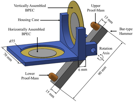
Figure 2.
Illustration of hammer-impact-driven power generator using buzzer-type piezoelectric energy converter.
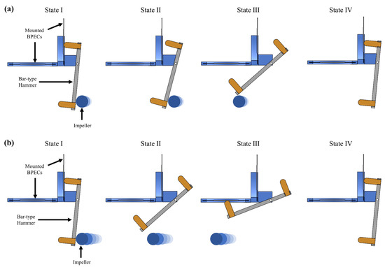
Figure 3.
Schematic images of periodic movements for hammer-impact-driven power generator under conditions of (a) weak impact and (b) strong impact.
Figure 3a shows schematic images of periodic movement for the hammer-impact-driven power generator under the condition of weak impact. All the images depict the side view, showing a direction of rotation axis vertical to the sheet. In the initial state, without any exterior force, the bar-type hammer was leaning against the face of the vertically aligned BPEC because the hammer’s rotation axis was not placed in a central position of the bar along the longitudinal direction and both tip-masses on the bar faced apart in different directions, as shown in State I of Figure 3a. If it is assumed that the stiff circular body moves slowly from right to left, as shown in States I, II, and III of Figure 3a, the proof-mass on the lower end of the bar-type hammer is steadily lifted up, while the proof-mass on the upper end of the bar-type hammer remains apart until the circular body completely departs from the hammer body. However, that lower proof-mass can never contact the surface of the horizontally aligned BPEC because of the relatively weak force transferred from the slowly moving body. Thereafter, the lower proof-mass was finally restored to the original state due to gravity and the upper proof-mass touched the surface of the vertically aligned BPEC, as shown in State IV of Figure 3.
On the other hand, it is expected that more dynamic movement, totally different from the case shown in Figure 3a, will happen to the hammer-impact-driven power generator under the assumption of strong impact transferred by a powerful and speedy circular body. Figure 3b provides schematic images of periodic movement for the hammer-impact-driven power generator under the condition of strong impact. Although the initial and final states, as shown in States I and IV in Figure 3a, were similar to those of the case of strong impact, the powerful and speedy circular body can lead the lower tip-mass to reach and impact the surface of the horizontally aligned BPEC, unlike the case of weak impact, as shown in State III in Figure 3b. The strong energy transmitted to the BPEC can form strain and, subsequently, generate electrical energy via the piezoelectric conversion mechanism. Thereafter, the lower tip-mass comes downward to the original state and the opposite upper tip-mass hits the surface of the vertically aligned BPEC with lessened impact.
Figure 4a shows an illustrated scheme of the handmade evaluation system to demonstrate power-generation performance of the hammer-impact-driven power generator as a function of the rotation speed of the impeller. Aside from the device under testing, the evaluation system comprising an electronic motor for which the rotations per minute (RPM) can be adjusted by an RPM controller. The rotation axis of the electronic motor is connected to a single impeller vertical to the rotation axis. This impeller is made of stainless steel with ϕ6 diameter; it has a length of approximately 270 mm. The electronic motor can also control the rotation speed of the impeller from 50 RPM to 1000 RPM. As can be seen in Figure 4a, the fabricated hammer-impact-driven power generator, assembled with the BPEC, is placed on the top surface of a large circular board 600 mm in diameter and 15 mm in thickness. When the impeller hits the backside of the bottom part of the bar-type hammer during rotation, which is opposite to the side of the lower tip-mass, the hammer imparts impact to the bottom surface of the BPEC in the horizontal slot, or not, depending on the impact intensity, as already shown in the simulation results presented in Figure 3a,b. Figure 4b provides a photo image of the handmade rotor system. It can be seen that a rectifying electric circuit is connected in parallel with the two BPECs to obtain the electrical output signal during operation. Although not shown in Figure 4a, several wide slits to clamp the power generator were formed along the radial direction of the transparent acrylic disk plate. In this work, demonstration of the performance of the impact-driven power generator was carried out at the outermost position of the slit in the disk plate. Snapshots taken by a high-speed camera are provided in Figure 5a–d, exhibiting side-views of the dynamic hammer-impact-driven power generator when the impeller rotates at speeds of 50, 100, 150, and 200 RPM, respectively. When the impeller moves at speeds less than 150 RPM, the bottom part of the bar-type hammer is forced up by the rotating impeller, but the two devices are still connected to each other due to the relatively weak rotational force (see Figure 5a,b). On the other hand, it was found that the collision condition of the lower tip-mass and the horizontal BPEC requires a rotation speed of at least 150 RPM, as shown in Figure 5c,d. More systematic experiments to achieve output electrical signals of the hammer-impact-driven power generator were conducted, and the results are introduced as a function of resistive load.
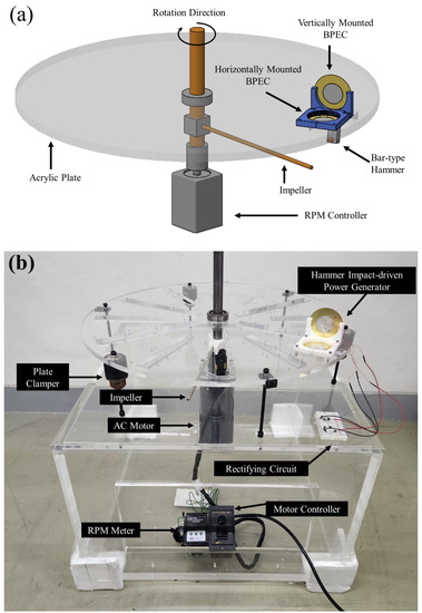
Figure 4.
(a) Schematic and (b) photo image of handmade evaluation system to demonstrate power-generation performance of hammer-impact-driven power generator as a function of the rotation speed of the impeller.
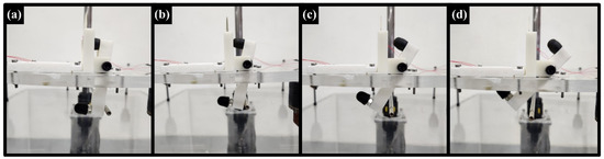
Figure 5.
Side views of dynamic hammer-impact-driven power generator when the impeller rotates at speeds of (a) 50, (b) 100, (c) 150, and (d) 200 RPM.
Figure 6a,b show the output-voltage and output-power characteristics of the hammer-impact-driven power generator, depending on the alignment direction of the buzzer-type piezoelectric energy converter. All output electric properties were evaluated in a range of resistive load of 10 Ω to 2 kΩ, at a constant impeller rotation speed of 150 RPM. Variations of the output voltage depending on the resistive load were similar in plot shape for both cases, irrespective of the alignment direction. The output voltage showed a tendency to increase with increasing load resistance. In detail, the output voltage increased drastically until the resistive load reached approximately 500 Ω, but it showed a saturated characteristic when the load resistance exceeded 500 Ω, as shown in Figure 6a. As shown in Figure 3, the impact occurring between the lower tip-mass and the horizontal BPEC, which is defined as the primary impact in this study, was expected to provide much higher power than impact by collision of the upper tip-mass and the vertical BPEC, defined as secondary impact in this study. The blue dotted line plots the primary impact, clearly showing higher values (approximately three times) of output voltage over the resistive load ranged of 500 Ω to 2 kΩ; this is in stark contrast to the secondary impact, represented by the red dotted line. In piezoelectric energy harvesting, according to the characteristics of the piezoelectric material, an impedance matching process, using a load resistor or an inductor, is required to obtain optimal output characteristics. In impedance matching, there is an optimal load resistance that can represent the maximum output power by the internal resistance of the piezoelectric material and the impedance of the circuit. One simple method of impedance matching is to produce an optimal output by changing the load resistance. Thus, it was considered that successful impedance matching in this system was probably achievable at a resistive load near 500 Ω. The output power of the hammer-impact-driven power generator showed a maximum value over the range of measured resistive load for both alignment directions. The maximum output power was commonly obtained at 500 Ω, as expected, thus indicating optimal load resistance. In particular, the maximum output power was as high as 670 mW at the optimal resistive load for the horizontal case, while a maximum power of 110 mW was achieved for the vertical case, as shown in Figure 6b. This magnitude of primary impact was almost six times higher than that of the secondary impact at the rotation speed of 150 RPM. However, since the impact difference can be dependent on the rotational velocity of the impeller, further experiments were performed to evaluate device power generation as a function of RPM.

Figure 6.
(a) Output-voltage and (b) output-power characteristics of hammer-impact-driven power generator, depending on alignment direction of buzzer-type piezoelectric energy converter, at 150 RPM, under various resistive loads, from 10 Ω to 2 kΩ.
Figure 7 shows variation of output voltage for the hammer-impact-driven power generator under optimal load resistance as a function of impeller rotation speed. Once the primary impact occurred between the lower tip-mass and the horizontal BPEC, the electrical output voltage signals were recorded during a half second for the given conditions of rotation speed, which ranged from 50 RPM to 250 RPM, at an interval of 50 RPM. Interestingly, only a single peak appeared when the rotation speed was less than 150 RPM. This implies that the primary impact did not occur, and only the secondary impact formed the voltage signal. The output voltage induced by the secondary impact was relatively low at approximately 7.5 V, which corresponds to approximately 110 mW of output power. However, whenever the rotation speed reached 150 RPM, a sharper and larger peak of output voltage started to appear prior to the formation of the small peak caused by the secondary impact. The increase of rotation speed to 250 RPM resulted in the appearance of an even higher peak output voltage delivered by the primary impact. Although the secondary impact was slightly enhanced by the increased rotation speed, this increase was not significant, because the difference between the primary and secondary impact expanded dramatically on the basis of the output voltage, as shown in Figure 7. Additionally, it was evident that the difference between the primary and secondary impact steadily increased as the rotation speed increased from 150 RPM to 250 RPM. The highest output voltages for only the primary impact were 18 V, 42 V, and 71 V at 150 RPM, 200 RPM, and 250 RPM, respectively. Therefore, it was notable that the rapid velocity of the rotating impeller was dominantly responsible for the enhancement of output voltage for this device. Nevertheless, the contribution of secondary impact to electric power generation should not be neglected, considering that the resultant output power was more frequent and had a steady-state value, being independent of the hammer’s rotation speed, along with having non-negligible values as large as 110 mW.
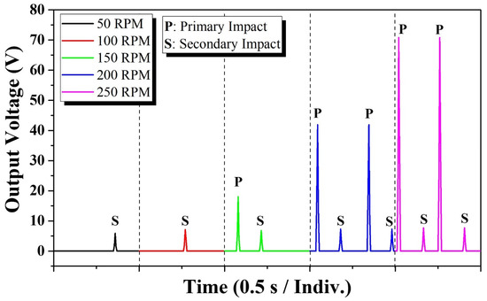
Figure 7.
Variation of output voltage for hammer-impact-driven power generator under optimal load resistance as a function of impeller rotation speed.
The output-voltage and output-power characteristics provided by the primary impact for the hammer-impact-driven power generator were also evaluated with the variation of the impeller rotation speed and resistive load, as shown in Figure 8a,b. Similar to the plots of output voltage and power for the rotation speed of 150 RPM, as already shown in Figure 6a,b, variations of output voltage and power in cases of increased rotation speeds of 200 RPM and 250 RPM showed similar tendencies toward the dependence on the resistive load. In all cases, the optimal resistive load was 500 Ω. However, the highest output power dramatically increased from 670 mW for 150 RPM to 3.3 W for 200 RPM to 10.4 W for 250 RPM, as shown in Figure 8b. Even rotation speeds faster than 250 RPM were experimented with, but the resultant data are not included in Figure 8 because the exceedingly strong impact transferred to the horizontal BPEC could badly damage the durability of the hammer-impact-driven power generator. The output-power performance obtained from the developed hammer-impact-driven power generator was highly notable compared to the previously reported performances (sub-W levels) of various piezoelectric energy converters for wind-energy-harvester applications [26,27,28,29,30]. However, the massive power generation originated from the extremely high voltage and low current (not shown), which are typical characteristics in piezoelectric energy conversion. Thus, usage of more BPECs in electrically parallel connection can be beneficial, broadening the peak sharpness of the output voltage and subsequently facilitating excellent electrical current, allowing the use of the developed hammer-impact-driven power generator for practical applications in wind-power generators.
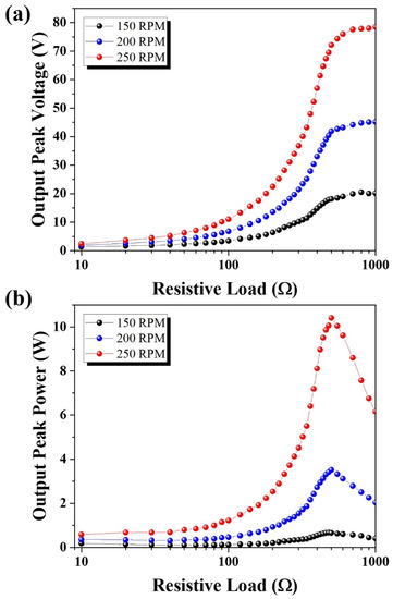
Figure 8.
(a) Output voltage and (b) output power characteristics provided by primary impact for hammer-impact-driven power generator with variation of impeller rotation speed and resistive load.
Figure 9 shows plots of resistive load-dependent output power provided by the primary impact for the hammer-impact-driven power generator array at an impeller rotation speed of 250 RPM. The output power characteristics were individually evaluated for a single power generator and an array of two and four generators, as shown in Figure 9a–c, respectively. Each inset image in those figures also includes a schematic top-view image representing the distribution of the hammer-impact-driven power generators, which were loaded on the top disk plate of the wind-power generator. Figure 9c provides an image of the wind-power generator assembled with the hammer-impact-driven power generator array in this study. In Figure 9b, it can be seen that the two power generators are exactly opposite each other on a line crossing the center on the disk plate. For the array in Figure 9c, four power generators were set regularly apart with internal angles of 90°. As already shown in Figure 8b, the output power of the single generator was as high as 10.4 W at 500 Ω, which is shown again to allow a comparison with the power performance of the arrays. As the number of power generators in the arrays increased, the optimal load resistance slightly decreased, implying improvement of the total electrical current. It was found that the value of load resistance at the highest output power declined from 500 Ω to 100 Ω with the increasing of the number of power generators. The output power did not linearly increase with the increasing of the number of power generators; this could be due to the enlarged resistance torque induced by the bar-type hammers, which are resistant to the rotational impellers during wind power generator operation. Nevertheless, in comparison to the case of the single power generator, a significantly enhanced output power of 14.4 W was obtained at a resistive load of 300 Ω for the array of two power generators. When the number of generators increased to four, approximately 18.8 W of output power was achievable.
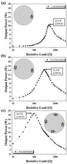
Figure 9.
Plots of resistive load-dependent output power provided by primary impact for hammer-impact-driven power generator array at impeller rotation speed of 250 RPM, with various numbers of power generators. (a) one generator; (b) two generators; (c) four generators.
Using a conventional hybrid Savonius–Darrieus turbine, further experiments were carried to demonstrate the performance of the hammer-impact-driven power generator. Figure 10 shows a photograph of the wind-power generator used for the demonstration; the experimental results are summarized in Table 3. As can be seen in Figure 10, wind speed is generated by commercial electric fans, and the generated wind energy activates the rotation of the hybrid Savonius–Darrieus turbine. The wind speed was controlled at 2.5 m/s, 5 m/s, and 7.5 m/s, and the estimated values of RPM for the hybrid turbines were 46, 132, and 276, respectively. In each condition, the output power of the developed device was evaluated for three cases of one, two, and four devices. Similar to the tendency of output power, which depends on the RPM and number of devices, as shown in Figure 8 and Figure 9, the improved output power performance depended on the corresponding parameters. In particular, when the wind speed and rotation of the turbine were 7 m/s and 276 RPM, the array of four power generators showed a significantly strong power output of 22 W, twice the generated power of the single generator. Table 4 provides a summary of output performance found in research on wind-power generators, using piezoelectric material similar to that used in this study.
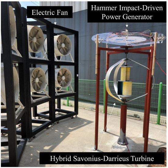
Figure 10.
Photograph of hammer-impact-driven power generator using conventional hybrid Savonius–Darrieus turbine.
Table 3.
Summary of output performance of hammer-impact-driven power generator with various wind conditions.
Table 4.
Performance comparison of various wind-energy harvesters using a piezoelectric material with wind turbines.
The designed hammer-impact-driven piezoelectric generator has the advantages of operating with a low impact force and greatly improving the output performance as rotation speed increases. However, when the rotation speed is high (300 RPM or more), mismatch caused a restoration cycle of the hammer body and the impact cycle of the rotation body, such that impact was unstable and the output performance slightly decreased.
4. Conclusions
A novel hammer-impact-driven power generator that uses a buzzer-type piezoelectric energy converter for wind-power-generator applications was designed, and dynamic motions were studied at various rotation speeds. As the active material, Sm-PMN-29PT ceramic, which has a high piezoelectric charge constant of 1100 pC/N and an electromechanical coupling factor of 58%, was used. When the rotating impeller collided with the bar-type hammer, the proof-masses at both ends of the bar-type hammer stroked the BPECs. At low-speed rotation, a vertically assembled converter dominantly operated. When the rotational speed increased, the output characteristics increased slightly because of the limitation of potential energy. At a high speed, a horizontally assembled device dominantly operated; the output performance increased significantly as the rotation speed increased. The developed device showed excellent energy-harvesting characteristics: the output power was 10.4 W at a resistive load of 500 Ω and rotation speed of 250 RPM. The generators were arrayed to improve the output characteristics. As the number of power generators in the array increased, the optimal load resistance slightly decreased; the output power did not linearly increase with the increasing number of power generators. The two-generator array exhibited an output performance of up to 14.4 W at a load resistance of 300 Ω and 250 RPM. For the four-generator array, the output power was 18.8 W at a load resistance of 100 Ω and 250 RPM. Hammer-impact-driven power generators were applied to wind power generators with a hybrid Savonius–Darrieus turbine to evaluate the output performance according to the wind speed. Using electric fans, the wind turbine was controlled to maintain a constant wind speed. At the starting wind speed of 2.5 m/s, the output power was 1.8 W; in the case of a strong wind of 7 m/s, the maximum output power was 22 W.
Author Contributions
Conceptualization, Y.H.J. and Y.N.; methodology, Y.H.J. and Y.N.; software, Y.N.; validation, S.N. and Y.H.J.; formal analysis, S.N., Y.N. and Y.H.J.; writing—original draft preparation, Y.N. and Y.H.J.; writing—review and editing, S.N. and Y.H.J.; visualization, Y.N.; supervision, Y.H.J.; project administration, Y.H.J.; funding acquisition, Y.H.J. All authors have read and agreed to the published version of the manuscript.
Funding
This research was financially supported by a New & Renewable Energy Technology Development Program (No. 20203030020280) of the Korea Institute of Energy Technology Evaluation and Planning (KETEP) grant funded by the Korea Government Ministry of Trade, Industry and Energy.
Data Availability Statement
Not applicable.
Conflicts of Interest
The authors declare no conflict of interest.
References
- Vasiliev, M.; Nur-E-Alam, M.; Alameh, K. Recent Developments in Solar Energy-Harvesting Technologies for Building Integration and Distributed Energy Generation. Energies 2019, 12, 1080. [Google Scholar] [CrossRef]
- Kishore, R.A.; Priya, S. A Review on Low-Grade Thermal Energy Harvesting: Materials, Methods and Devices. Materials 2018, 11, 1433. [Google Scholar] [CrossRef] [PubMed]
- Shin, Y.-H.; Choi, J.; Kim, S.J.; Kim, S.; Maurya, D.; Sung, T.-H.; Priya, S.; Kang, C.-Y.; Song, H.-C. Automatic resonance tuning mechanism for ultra-wide bandwidth mechanical energy harvesting. Nano Energy 2020, 77, 104986. [Google Scholar] [CrossRef]
- Yu, X.; Hou, Y.; Zhao, H.; Fu, J.; Zheng, M.; Zhu, M. The role of secondary phase in enhancing transduction coefficient of piezoelectric energy harvesting composites. J. Mater. Chem. C 2019, 7, 3479–3485. [Google Scholar] [CrossRef]
- Song, H.-C.; Kim, S.-W.; Kim, H.S.; Lee, D.-G.; Kang, C.-Y.; Nahm, S. Piezoelectric Energy Harvesting Design Principles for Materials and Structures: Material Figure-of-Merit and Self-Resonance Tuning. Adv. Mater. 2020, 32, 2002208. [Google Scholar] [CrossRef]
- Pu, T.; Chen, H.; Xing, J.; Luo, Y.; Fan, S.; Liu, H.; Chen, Q.; Zhu, J. Ultra-high-temperature piezoelectric responses and ultra-high thermal stability of piezoelectricity in ceramic PbZr0.54Ti0.46O3. J. Am. Ceram. Soc. 2022, 105, 4152–4160. [Google Scholar] [CrossRef]
- Chen, H.; Pu, T.; Luo, Y.; Fan, S.; Chen, Q.; Liu, H.; Zhu, J. Enhancement of Piezoelectric Properties in Low-Temperature Sintering PZN–PZT Ceramics by Sr2+ Substitution. J. Electron. Mater. 2022, 51, 1261–1271. [Google Scholar] [CrossRef]
- Luo, Y.; Pu, T.; Fan, S.; Liu, H.; Zhu, J. Enhanced piezoelectric properties in low-temperature sintering PZN-PZT ceramics by adjusting Zr/Ti ratio. J. Adv. Dielectr. 2022, 12, 2250001. [Google Scholar] [CrossRef]
- Gao, X.; Wu, J.; Yu, Y.; Chu, Z.; Shi, H.; Dong, S. Giant Piezoelectric Coefficients in Relaxor Piezoelectric Ceramic PNN-PZT for Vibration Energy Harvesting. Adv. Funct. Mater. 2018, 28, 1706895. [Google Scholar] [CrossRef]
- Zhang, J.; Zhang, Y.; Yan, Z.; Wang, A.; Jiang, P.; Zhong, M. Fabrication and performance of PNN-PZT piezoelectric ceramics obtained by low-temperature sintering. Sci. Eng. Compos. Mater. 2020, 27, 359–365. [Google Scholar] [CrossRef]
- Chang, Y.; Wu, J.; Liu, Z.; Sun, E.; Liu, L.; Kou, Q.; Li, F.; Yang, B.; Cao, W. Grain-Oriented Ferroelectric Ceramics with Single-Crystal-like Piezoelectric Properties and Low Texture Temperature. ACS Appl. Mater. Interfaces 2020, 12, 38415–38424. [Google Scholar] [CrossRef] [PubMed]
- Brova, M.J.; Watson, B.H.; Walton, R.L.; Kupp, E.; Fanton, M.A.; Meyer, R.J.; Messing, G.L. Relationship between composition and electromechanical properties of CuO-doped textured PYN-PMN-PT Ceramics. J. Eur. Ceram. Soc. 2021, 41, 1230–1235. [Google Scholar] [CrossRef]
- Li, K.; Sun, E.; Zhang, Y.; Song, Z.; Qi, X.; Sun, Y.; Li, J.; Yang, B.; Liu, J.; Cao, W. High piezoelectricity of Eu3+-doped Pb(Mg1/3Nb2/3)O3–0.25PbTiO3 transparent ceramics. J. Mater. Chem. C 2021, 9, 2426–2436. [Google Scholar] [CrossRef]
- Wang, P.; Guo, Q.; Li, F.; Xia, F.; Hao, H.; Sun, H.; Liu, H.; Zhang, S. Modified Pb(Mg1/3Nb2/3)O3-PbZrO3–PbTiO3 ceramics with high piezoelectricity and temperature stability. J. Am. Ceram. Soc. 2021, 104, 5127–5137. [Google Scholar] [CrossRef]
- Han, F.; Qin, Y.; Zhang, Y.; Yan, P.; Wang, Y.; Guo, P.; Li, F. Domain configuration and domain switching in Dy-doped 0.72PMN-0.28PT Piezoceramics with high d33 coefficient. Ceram. Int. 2022, 48, 23061–23071. [Google Scholar] [CrossRef]
- Li, F.; Lin, D.; Chen, Z.; Cheng, Z.; Wang, J.; Li, C.; Xu, Z.; Huang, Q.; Liao, X.; Chen, L.Q.; et al. Ultrahigh piezoelectricity in ferroelectric ceramics by design. Nat. Mater. 2018, 17, 349–354. [Google Scholar] [CrossRef]
- Gao, B.; Yao, Z.; Lai, D.; Guo, Q.; Pan, W.; Hao, H.; Cao, M.; Liu, H. Unexpectedly high piezoelectric response in Sm-doped PZT ceramics beyond the morphotropic phase boundary region. J. Alloys Compd. 2020, 836, 155474. [Google Scholar] [CrossRef]
- Lee, M.-S.; Na, Y.-H.; Park, J.-W.; Jeong, Y.H. Aeroelastic flutter energy harvesting performance from piezoelectric fiber composite array using Pb(Zr,Ti)O3-Pb(Ni,Nb)O3 laminates. Jpn. J. Appl. Phys. 2020, 59, 106505. [Google Scholar] [CrossRef]
- Liu, J.; Zuo, H.; Xia, W.; Luo, Y.; Yao, D.; Chen, Y.; Wang, K.; Li, Q. Wind energy harvesting using piezoelectric macro fiber composites based on flutter mode. Microelectron. Eng. 2020, 231, 111333. [Google Scholar] [CrossRef]
- Yang, K.; Wang, J.; Yurchenko, D. A double-beam piezo-magneto-elastic wind energy harvester for improving the galloping-based energy harvesting. Appl. Phys. Lett. 2019, 115, 193901. [Google Scholar] [CrossRef]
- Zhang, H.; Song, R.; Meng, J.; Li, X.; Sui, W.; Yang, X. A direction adaptive hybrid piezo-electromagnetic energy harvester based on vortex-induced vibration. Ferroelectrics 2021, 584, 113–120. [Google Scholar] [CrossRef]
- Bolat, F.C.; Basaran, S.; Sivrioglu, S. Piezoelectric and electromagnetic hybrid energy harvesting with low-frequency vibrations of an aerodynamic profile under the air effect. Mech. Syst. Signal Process. 2019, 133, 106246. [Google Scholar] [CrossRef]
- Bao, C.; Dai, Y.; Wang, P.; Tang, G. A piezoelectric energy harvesting scheme based on stall flutter of airfoil section. Eur. J. Mech. B/Fluids 2019, 75, 119–132. [Google Scholar] [CrossRef]
- Orrego, S.; Shoele, K.; Ruas, A.; Doran, K.; Caggiano, B.; Mittal, R.; Kang, S.H. Harvesting ambient wind energy with an inverted piezoelectric flag. Appl. Energy 2017, 194, 212–222. [Google Scholar] [CrossRef]
- Kan, J.; Fan, C.; Wang, S.; Zhang, Z.; Wen, J.; Huang, L. Study on a piezo-windmill for energy harvesting. Renew. Energy 2016, 97, 210–217. [Google Scholar] [CrossRef]
- Paulo e Silva, A.G.; Basílio Sobrinho, J.M.; da Rocha Souto, C.; Ries, A.; de Castro, A.C. Design, modelling and experimental analysis of a piezoelectric wind energy generator for low-power applications. Sens. Actuators A Phys. 2021, 317, 112462. [Google Scholar] [CrossRef]
- Kan, J.; Wang, J.; Wu, Y.; Chen, S.; Wang, S.; Jiang, Y.; Zhang, Z. Energy harvesting from wind by an axially retractable bracket-shaped piezoelectric vibrator excited by magnetic force. Energy 2022, 240, 122495. [Google Scholar] [CrossRef]
- Akbari, A.M.; Yaghoubirad, M.; Zareie, Z.; Azizi, N.; Goodini, M.J.; Tahmouresi, R.; Soleimani Khoshru, A.R.; Eghbali, P.; Farajollahi, M. Piezomagnetic cantilever stator energy harvester using Savonius wind rotor. Sustain. Energy Technol. Assess. 2022, 50, 101826. [Google Scholar] [CrossRef]
- Na, Y.; Lee, M.-S.; Lee, J.W.; Jeong, Y.H. Wind energy harvesting from a magnetically coupled piezoelectric bimorph cantilever array based on a dynamic magneto-piezo-elastic structure. Appl. Energy 2020, 264, 114710. [Google Scholar] [CrossRef]
- Na, Y.; Lee, M.-S.; Lee, J.W.; Jeong, Y.H. Horizontally Assembled Trapezoidal Piezoelectric Cantilevers Driven by Magnetic Coupling for Rotational Energy Harvester Applications. Energies 2021, 14, 498. [Google Scholar] [CrossRef]
- Wang, J.; Gu, S.; Abdelkefi, A.; Zhang, M.; Xu, W.; Lai, Y. Piezoelectric energy harvesting from flow-induced vibrations of a square cylinder at various angles of attack. Smart Mater. Struct. 2021, 30, 08LT02. [Google Scholar] [CrossRef]
- Hagood, N.W.; Chung, W.H.; Von Flotow, A. Modelling of Piezoelectric Actuator Dynamics for Active Structural Control. J. Intell. Mater. Syst. Struct. 1990, 1, 327–354. [Google Scholar] [CrossRef]
- Liao, Y.; Sodano, H.A. Model of a single mode energy harvester and properties for optimal power generation. Smart Mater. Struct. 2008, 17, 065026. [Google Scholar] [CrossRef]
- Yabin, L.; Sodano, H.A. Structural Effects and Energy Conversion Efficiency of Power Harvesting. J. Intell. Mater. Syst. Struct. 2008, 20, 505–514. [Google Scholar] [CrossRef]


Publisher’s Note: MDPI stays neutral with regard to jurisdictional claims in published maps and institutional affiliations. |
© 2022 by the authors. Licensee MDPI, Basel, Switzerland. This article is an open access article distributed under the terms and conditions of the Creative Commons Attribution (CC BY) license (https://creativecommons.org/licenses/by/4.0/).