Article

Implementation and Validation for Multitasks of a Cost-Effective Scheme Based on ESS and Braking Resistors in PMSG Wind Turbine Systems

1
Faculty of Engineering Technology and Science, Higher Colleges of Technology, Dubai P.O. Box 16062, United Arab Emirates
2
Faculty of Computer Information Systems, Higher Colleges of Technology, Dubai P.O. Box 16062, United Arab Emirates
3
Department of Electrical and Electronics Engineering, Ho Chi Minh City University of Food Industry, 140 Le Trong Tan, Ho Chi Minh City P.O. Box 760310, Vietnam
*
Author to whom correspondence should be addressed.
Energies 2022, 15(21), 8282; https://doi.org/10.3390/en15218282
Submission received: 26 August 2022 / Revised: 25 October 2022 / Accepted: 29 October 2022 / Published: 5 November 2022
(This article belongs to the Special Issue Advances in Renewable Energy Research and Applications)

Abstract

:
This study deals with fault ride-through (FRT) capability and output power fluctuation suppression of wind turbine systems (WTS) having PMSG (permanent-magnet synchronous generator) for mitigating grid frequency variation and voltage flicker in the distribution system. The coordinated control of a cost-effective scheme based on energy storage supercapacitors (ESSs) and braking resistors (BR) is introduced to perform the multiple tasks of the WTS. In this hybrid scheme, the ESSs are initially used to absorb the fluctuated power component with the constraints of their ratings during the grid faults and wind speed variation conditions prior to the activation of the BRs when the ESSs cannot fully consume the mismatched power between the PMSG and grid during severe grid faults. With the additional BRs, the capacity of the costly ESSs is remarkably reduced, while the performance of the fault ride-through capability and power smoothening for the WTS are still kept satisfactory and in compliance with the requirements of advanced grid codes. Detailed experimental implementation and its results for a down-scaled prototype in a laboratory are shown to verify the effectiveness of the introduced scheme along with the simulation results with the high-power rating WTS.

1. Introduction

Nowadays, renewable energy has attracted considerable attention since fossil fuels are being exhausted and environmental issues have become more serious. Wind energy is one of the most important renewable energy sources [1,2,3,4,5], where the significant penetration of wind power capacity may cause some problems in the power systems, such as grid instability, unbalance, and frequency variation [6,7].
The first issue is that a large amount of electrical power generated by the WTS may lead to adverse effects on the power quality of the network due to randomly varying wind speeds. In this condition, the output power fluctuation of the WTS incurs an imbalance of power between generation and consumption, which results in a deviation of the line frequency from its rated value. Therefore, suppressing the fluctuating components of WTS output power is essential. Another concern is the FRT capability of the WTS under grid fault conditions, where the WTS are required to remain in service and be able to provide reactive power to the network.
In the published literature, in order to mitigate the power fluctuation of the WTS, several power smoothening strategies have been suggested. By exploiting the high inertia effect of the WTS, the turbine power fluctuation can be smoothened to support the frequency regulation for the network [8,9], where no extra apparatus is required. However, its response is slow due to the high rotor inertia, and the smoothened power capacity is limited. Another method using a flywheel system was presented in [10,11], which utilizes simple control schemes. However, the flywheel system is bulky and costly. The pitch angles of the wind turbine blades with the rotor velocity can be regulated to smooth the output power of the WTS, but the WTS loses the maximum power-point tracking operation [12]. With the development and current availability of the energy storage systems, utilization of the energy storage systems to improve the power quality of the WTS has been introduced, where the battery energy storage systems or the hybrid system combining the batteries and supercapacitors are both suggested [13,14]. The main issues of using energy storage systems are high capital investment and maintenance costs.
In order to comply with the requirements of advanced grid codes under grid faults, a braking chopper has been considered a preferred and practical solution, which provides a lower cost and a simple control [15,16]. However, this scheme is used only for the FRT, which is not capable of improving the power quality. Other methods with modification of the control algorithms, such as the current feed-forward method, sliding mode control scheme, and robust adaptive PI controller, have been introduced to improve the response of the WTS during the grid faults [17,18]. Installing the energy storage systems at the connection point of the wind plants can achieve many objectives such as fluctuated power smoothing and providing the FRT capability etc. [19]. Other solutions with the ESSs distributed to single WTS at the back-to-back (B2B) converters through a bidirectional DC/DC converter (BDCC) were introduced [20], which can offer both an FRT capability and power fluctuation mitigation for the WTS. However, the required capacity of the ESS is still high to handle extremely severe grid faults, such as full interruptions of two or three phases of grid voltages, which rarely occur in practice compared to phase-to-phase or phase-to-ground short-circuit faults. Under such faults, the grid can partly absorb real power from the WTS. So, the mismatched power between the wind generator and grid under the common grid faults is less than the rated power of the system. For this scenario, employing the ESSs with a full rating is costly and unnecessary. The required rating of the ESS can be reduced by the de-loaded operation of the WTS, where the output power of the wind turbine generator is reduced [21]. This algorithm can be acceptable, but the WTS is not operating at the MPPT control. A hybrid scheme of the ESS and BR in the WTS was suggested [22,23], where the power capacity of the ESS was lowered. However, the improvement of power quality by installing ESS was not fully investigated, and a control mode switch for the grid-side converter and the BDCC between the normal and fault conditions may cause a current overshot in the system. These issues have not been presented in any of the literature so far.
This paper presents a coordinated control of the ESS and BR for improving the power quality as well as riding through the PMSG WTS, which guarantees a secure and smooth operation of the WTS during normal and severe grid fault conditions. The ESSs are utilized to absorb the fluctuation component of turbine power before injecting it into the grid under the wind speed variation, which smoothens the grid power. Under the grid sags, the ESSs consume a certain level of mismatched power between the PMSG and the network, and the rest is then dissipated by the BRs. A cascaded control of the outer power loop and inner current loop is applied for the BDCC, and a control strategy associated with the ESSs is used for the BRs, was compensation for a phase shift caused by the high-pass filter is employed to obtain an effective power reference of the ESS. With this control scheme, the required capacity of the ESSs is significantly reduced, while both the performances of the power fluctuation mitigation and the FRT under severe faults of the grid are still kept well.
The detailed experimental implementation for a down-scaled prototype in the laboratory is presented to validate the multiple tasks of PMSG WTS, where the squirrel-cage induction motor is used to simulate the characteristics of the wind turbine with the output power depending on the wind speed. The DSP TMS320VC33 chips are used as the main controller boards in the experimental test systems. The experimental results also demonstrate the simulation results for a 2-MW PMSG WTS. The additional contributions of this work are that a switching control mode of the grid-side converter and the BDCC between the normal and fault conditions are not required, and a phase-shift delay compensation for obtaining the power reference of the ESS is employed.

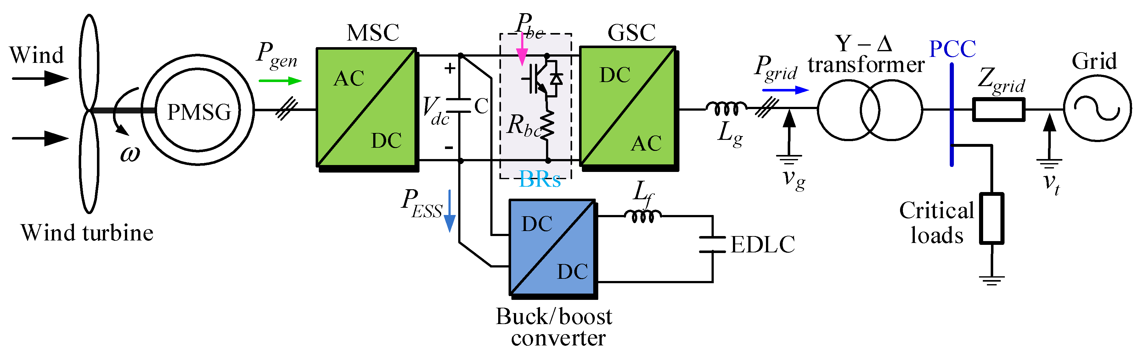
2. Control Scheme of PMSG Wind Turbine Systems

The ESS can be installed in the wind power plants by either a distributed connection to the single WTS or a centralized connection at the wind power plant terminal, where the distributed ESS can not only smoothen the output power of the WTS but also provide an FRT capability under the grid faults. A typical configuration of a direct-drive PMSG WTS with the hybrid scheme of the distributed ESS and BR is shown in Figure 1 [23]. The ESS in this work adopts electric double-layer capacitors (EDLC), which are linked to the DC link of the B2B converters through a BDCC. The BR is connected in parallel with the DC link through a switch. With this configuration, the hybrid scheme of the ESS and BR is well fit for the wind turbine systems with full-scale capacity converters such as PMSG-based wind turbine systems, while this scheme is not suitable to apply for the DFIG-based wind turbine systems because the rating of the converters in the rotor side is already as low as 30% of the system rating.

2.1. Turbine Inertial Effect for Absorbing Power under Grid Faults

When grid faults occur, the real power injected into the grid will be restricted due to the limited current rating of the power converters. In order to reduce the mismatch of power between the PMSG and grid, which is to be absorbed by the ESS and BR, the wind turbine is accelerated to reduce the turbine output power since a part of the amount of energy due to inertial effect is required for the acceleration action.
A torque equation for a two-mass model of WTS is expressed as [20,24,25]
T t T g = ( J t + J g ) d ω d t  
where Tt, Tg, and Jt, Jg are the torques and inertias of the turbine and PMSG, respectively, and ω is the turbine speed.
For storing the inertial energy, the speed of the turbine is increased by controlling the PMSG. A time interval of the fault and a gradient of the speed is defined as Δ T and Δ k (%), respectively. An inertial power, PJ, due to a speed change is given based on the constant inertia definition and (1) as [26]
P J = 2 · P r a t e d ( H T + H G ) Δ k Δ T  
where HT and HG are the turbine and generator inertia constants, respectively, and Prated is the power rating.

2.2. Control of Grid-Side Converter

The grid-side converter (GSC) is used to control the DC-link voltage and the currents flowing into the network. Figure 2 depicts the control scheme of the GSC, where a cascaded control scheme with the main loop of DC-link voltage and an inner loop of grid currents is employed [27,28]. Initially, the positive- and negative-sequence components (PSC and NSC) of dq-axis grid voltages and currents, E d q e p , n     and     I d q e p , n , respectively, are decomposed by digital all-pass filters and Park’s transformation, which then a decouple synchronous reference frame PLL (phase-locked loop) for the three-phase system is applied to detect the grid phase angle [29,30]. The phase angle of the negative-sequence voltage component is set as the opposite of the positive-sequence one.
The typical PI (proportional integral) regulators are employed for the DC-link voltage controllers, which determine the amount of real power delivered to the grid. The control algorithm is applied for both symmetrical and asymmetrical faults of grid voltages, where the PSC and NSC of the grid currents are regulated. To guarantee the active power of PMSG delivered to the grid fully, which keeps the DC-link voltage unchanged, along with the PSC of the grid currents, NSC is also required to be injected into the grid, where the dq-axes current reference of the PSC and NSC, I d e p * ,   I q e p * ,   I d e n * ,   I q e n * , respectively, are determined as below:
I q e p * = V d c * × I d c * 2 E q e p 3 D   and   I d e p * = V d c * × I d c * 2 E d e p 3 D I q e n * = V d c * × I d c * 2 E q e n 3 D   and   I d e n * = V d c * × I d c * 2 E d e n 3 D
V d c * is the DC-link voltage reference, I d c * is the output of the DC-link voltage controller, E d e p ,   E q e p ,   E d e n ,   E q e n are the dq-axes voltage components of the PSC and NSC of the grid voltage, respectively and D = ( E d e p ) 2 + ( E q e p ) 2 ( E d e n ) 2 ( E q e n ) 2 .
The PI regulators are also applied for the current controllers for all components, as shown in Figure 2. The controller gains are designed following the guidelines in [27,28], which are listed in Figure 2 as K v c = K p v c = 0.82   ;     K i v c = 0.82   ; τ v c = 0.013 for the DC-link voltage controller and K c c = K p c c = 1.5   ;     K i c c = 930   ; τ c c = 0.0016 for the grid current controllers. It is noted that by absorbing the PMSG power in the ESS and BR under the grid faults, the GSC remains at a margin to provide reactive power to the grid as required by the grid code [23,31,32], even though this issue is not investigated in this work.

2.3. Control of Machine-Side Converter (MSC)

Figure 3 shows a control scheme of PMSG under both normal and fault conditions. A vector control method is applied for the PMSG, where the dq axes of generator currents are regulated. An operation of maximum torque per ampere method for the PMSG is utilized, where the d-axis generator current is regulated to zero. So, the q-axis generator current is used to adjust the generator’s real power, where the reference of the q-axis component is determined from the generator speed controller. The PI controller gains of the machine speed and currents are depicted in Figure 3 as K s c = K p s c = 10,125   ;     K i s c = 81,000   ; τ s c = 0.125 and K c c = K p c c = 0.518   ;     K i c c = 388   ; τ c c = 0.00133 , respectively, which are designed based on the pole-placement technique [33]. Under the normal grid condition, the maximum power point tracking (MPPT) operation of the WTS is applied [34,35], which sets the generator speed reference at the optimal value for the speed controller, as shown in Figure 3. However, when the grid sag occurs, to reduce the output power of WTS, the MPPT operation is deactivated, and the turbine is accelerated. The acceleration rate of the turbine depends on the inertia constant of the system and the speed control parameters, where the selection procedure of the acceleration rate has been described in detail in [23].
In this work, the acceleration rate, k, is chosen as 1.0005 [23]. The acceleration of the turbine causes a reduction in the output power of WTS according to two following reasons. Firstly, when the MPPT operation is not maintained due to increasing the turbine speed, the tip-speed ratio, λ, is not kept at the optimal value, λopt. So, the power conversion coefficient, Cp, is lower than the maximum one, Cpmax, which can be expressed as
ω > ω o p t { λ > λ o p t C p < C p max P t < P t , max
where Pt is the turbine power and Pt,max is the optimal turbine power at a certain speed.
Secondly, a portion of the power extracted from wind is stored in the turbine inertia as in (2) during the acceleration of the turbine, so the generator output power, Pgen, is reduced according to the acceleration of the turbine expressed as:
P g e n = P t P J

3. Power Smoothing Operation and FRT Control

In a weak distribution system with a low X/R ratio, the fluctuation of the WTS output power may cause a voltage flicker at the point of common coupling, which has negative effects on critical loads [8]. By smoothing the output power of WTS associated with the reactive power injection, the voltage flicker, as well as the frequency variation, would be mitigated. In this work, the power smoothening operation and FRT control for the PMSG WTS in the distribution system are mainly investigated.

3.1. Calculation of Power References for the ESS

During the voltage dips, the real power injected into the network by the GSC is limited, which can be lowered than that of PMSG due to a reduction in grid voltage and a fixed current rating of GSC. The differential power is absorbed by the ESSs and BRs to avoid an overvoltage in the DC-link capacitors, which can be described as
P d i f f = P g e n P g r i d | max   p o s i b i l i t y
where Pdiff is the surplus power of the PMSG and grid, and Pgrid is the power injected into the power line through the GSC. In this operation, the GSC is controlled to inject the generator power into the network as high as possible with consideration of its current constraint.
It has been reported that the fluctuated power of the WTS in a frequency range of (0.05~1) Hz results in a deviation of the line frequency [8]. So, in order to improve the quality of the WTS power under normal conditions, the fluctuated component of the WTS output power should be suppressed, where the ESSs are utilized to absorb these components caused by random wind speed conditions. The high-frequency power component of PMSG, Pfluc, is extracted by the high-pass filter (HPF), which is expressed as
P f l u c = s 2 s 2 + 2 ξ ω c s + ω c 2 P g e n  
where in this work, the lowest frequency or cut-off frequency of the HPF is chosen as 0.05 Hz and ξ = 0.707 and ω c = 2 × π × 0.05 = 0.314 rad/s, which makes sure that the higher frequency components are also extracted for compensating by the ESS.
To improve the real power injected into the grid and the performance of the ESS, the phase shift of the second order HPF should be compensated. A lead-lag compensator is utilized for a phase-shift compensation at the cut-off frequency, where its transfer function, G c o m p ( s ) , is expressed as
G c o m p ( s ) = K c o m p 1 + a 1 s 1 + a 2 s
where the pole of the lead-lag compensator is selected according to the cut-off frequency of the HPF as a 2 = 1 ω c 2 = 1 0.314 10 , and the zero is chosen by placing it 10 times further from the pole as a1 = 1. Kcomp is selected as 10 to obtain a unity gain for high-frequency operation range.
Finally, the power reference of the ESSs is determined as
P f l u c = 10 1 + s 1 + 10 s · s 2 s 2 + 2 ξ ω c s + ω c 2 P g e n
Utilizing the above power reference of the ESSs, the main objective of controlling the ESSs is to suppress the fluctuation component of the WTS output power. The optimal charge and discharge of the ESSs for minimizing the operational cost and power losses and prolonging the lifetime of the ESSs are beyond the scope of this work.

3.2. Control of the ESS

The real power is stored or released from the ESSs by controlling the BDCC, where its control scheme diagram is depicted in Figure 4. Under both normal and voltage sag conditions, the real power is a control target of the ESSs, where the power references are determined in (8) and (5) for the two cases, respectively. A cascaded control scheme is adopted for the BDCC, which consists of an outer PI loop for the power and an inner PI loop for the inductor current. From Figure 4, the output of the power controller, which is the inductor current reference, I E S S * , is given as
I E S S * = K p p c ( P E S S * P E S S ) + K i p c s ( P E S S * P E S S )
and   P E S S = V E S S I E S S
where P E S S is the ESS power, V E S S     and     I E S S are the ESS voltage and current, respectively, K p p c     and     K i p c are the power controller gains.
Then, the transfer function for the power controller is expressed as
P E S S P E S S * = K p p c s + K i p c ( 1 V E S S + K p p c ) s + K i p c 1       for     all     s
In this work, the power controller gains are selected by a trial-and-error method as K p p c = 0.005 ,     K i p c = 0.472 ,     and     τ p c = 0.0106 . Note that the bandwidth of the power controller is low, which is about 100 Hz.
It is seen from Figure 4 the output of the current controller, V L f * , is expressed as [36]
V L f * = K p c c ( I E S S * I E S S ) + K i c c s ( I E S S * I E S S )
where K p c c     and     K i c c are the ESS current controller gains, which are selected following the pole-placement technique as K p c c = 0.89 ,     K i c c = 840 ,     and     τ c c = 0.00106 [36].
Based on the output of the current controller, which is the inductor voltage reference, the duty cycle, DESS, for the DC/DC converter is determined by
D E S S = V E S S + V L f * V d c
where Vdc is the DC-link voltage.
The duty cycle is compared to a carrier signal to generate the gating signals for switches S1 and S2 of the BDCC. In this work, the carrier frequency is selected as 2 kHz.

3.3. Control of the BRs

The braking chopper is only operated when the ESSs cannot absorb fully a surplus power between the PMSG and the grid, which is shown in Figure 4. The switch S3 is allocated to adjust the power consumed by the BR, where its duty cycle is determined from the required power and the braking resistance, Rbc, expressed as
D S 3 = R b c V d c 2 P b c
where Pbc is the power command for the BRs, which is calculated as
P b c = { P d i f f P E S S _ r a t e d 0           :         fault     condition P f l u c P E S S _ r a t e d   0           :         normal     condition   .
It is worth noting that the pole-placement technique is adopted to design the controller gains, where the PI gains of all controllers have been obtained for the studied systems. For the field deployment system, this method can be used to obtain the gain with fine-tuning to achieve good performance.

4. Ratings of the ESSs and the BRs

The ESS is utilized to consume the fluctuated power components of the WTS in the normal grid condition, where the capacity of the ESS is selected appropriately in terms of power and energy ratings to mitigate the output power fluctuation for a certain frequency range. It is noted that this work does not target to forecast or model the accurate wind speed patterns, so a simple time-period model of randomly varying wind speed, which causes the fluctuated power of WTS; is used as expressed below [37]:
v ( t ) = A 0 + Δ A i sin ( 2 π f i t )
where A0 is the mean wind speed, ∆Ai is the magnitudes of turbulences of wind speed, and fi is the frequencies (fi = 0.05~10 Hz).
For a short-term fluctuation of wind power, the output power variation is low, where the power fluctuation is mostly within 30% of its average [8]. So, the power rating of the ESSs is selected as
P E S S _ r a t e d = 0.3 P r a t e d .
Then, the energy rating of the ESS is selected depending on turbulent components of wind speed and frequency range, where the ESSs can absorb the fluctuated power component. The energy stored in the ESSs is expressed as
E E S S _ r a t e d = 0 1 / 2 f i P E S S _ r a t e d sin ( 2 π f i t ) .
The EDLC capacitance, C, is selected from its ratings of the voltage and energy as
C = 2 · E E S S _ r a t e d Δ V c a p · V c a p r a t e d
where V c a p r a t e d and Δ V c a p are the ratings of EDLC voltage and its allowable variation, respectively.
A decreased amount of the grid power under grid voltage sag conditions, PLVRT, for the worst case, can be determined from the grid codes as
P L V R T = ( 1 V min , p u ) P r a t e d
where Vmin,pu is a lower limit level of the grid voltage determined from the grid codes.
Finally, the power rating and resistance of the BRs are determined as
P b c _ r a t e d = P L V R T P E S S _ r a t e d P J   and   R b c = V d c 2 P b c _ r a t e d .
Based on the rating design above, an approximate cost comparison between using only ESS and the hybrid scheme of ESS and braking resistors is carried out applying to 2 MW wind turbine system, which is shown in Table 1. The power rating of the ESS is selected as 2 MW if only ESS is used, while the power ratings of the ESS and braking resistor are chosen as 0.6 MW and 1.4 MW, respectively, for the hybrid scheme. It is shown in Table 1 that the total cost of the hybrid system is about 36.24% compared to that of the system using only the ESS.
It is stated that the main concerns of the research are on the FRT capability and output power fluctuation suppression. However, it is worth noting that the PMSG-based WTSs with the hybrid scheme of the ESSs and the BRs, as shown in Figure 1, are able to operate in a standalone mode instead of grid connection, where the control targets of the GSC and the buck/boost DC-DC converter need to be changed, and the MSC is still controlled to track the maximum power from wind. For the standalone mode, the BDCC is allocated to maintain the DC-link voltage, while the GSC is used to regulate the AC voltages of the loads or the PCC.

5. Simulation Results

PSIM simulation tests were carried out for a PMSG WTS with a rating of 2 MW to verify the effectiveness of the presented scheme. The specifications of the WTS and PMSG are listed in Table 2, and the parameters of the ESSs and the BRs are listed in Table 3, which are designed as per the guidelines described in Section 4. The terminal voltage of BTB converters is 0.69-kV/60-Hz.

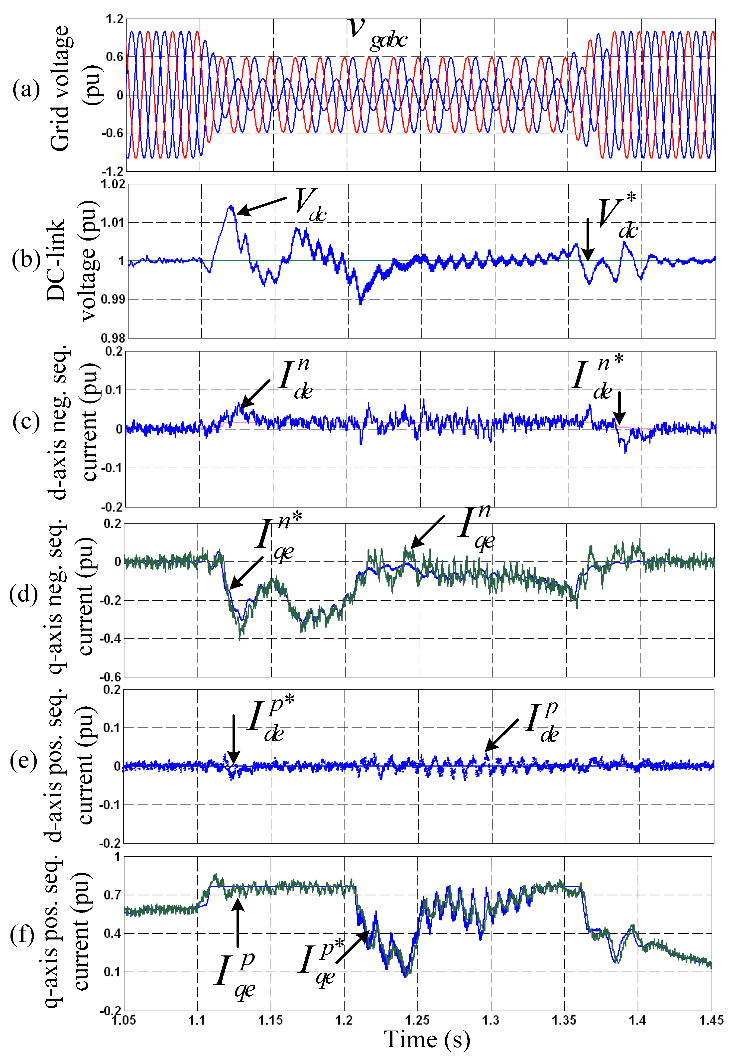
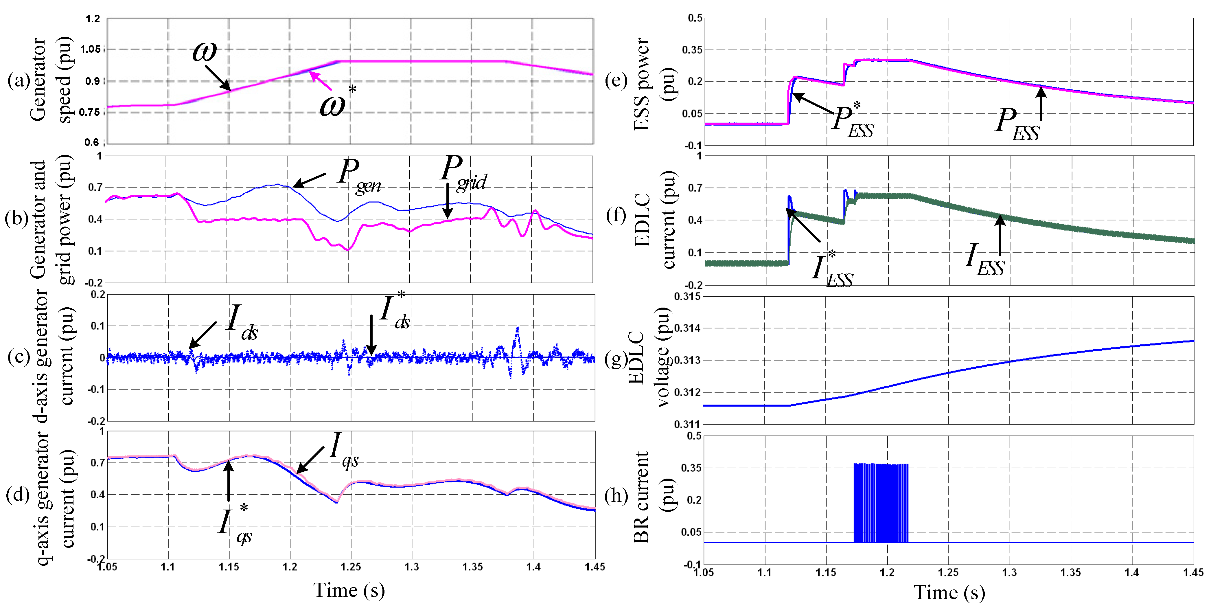
5.1. Test for a Fault Ride-Through Capability

The control performance of the GSC under the unbalanced voltage sag condition is illustrated in Figure 5. Figure 5a shows the three-phase grid voltages, which drop to 60%, 60%, and 25%, respectively, for three-phase voltages, for 250 ms. Figure 5b shows the DC-link voltage, which is maintained close to its rating of 1.2 kV with an overshoot value of less than 1.5%. It is illustrated in Figure 5c–f that the control performances of dual-current controllers for the P_NSC of the dq-axis grid currents, respectively, are satisfactory. Under unbalanced sag, the NSC of grid currents exists, as shown in Figure 5c,d. It is also demonstrated in Figure 5 that before and after the sag, the GSC works well.
Figure 6 shows the response of the WTS and the control response of PMSG, ESS, and BR under the fault. The speed of WTS is shown in Figure 6a, where the turbine speed starts increasing at the instant of the fault detected, which causes a reduction in the turbine output power. The PMSG and grid powers are shown in Figure 6b, where the grid power is lower than the generator power. The mismatch power is absorbed by the ESSs and BRs. The dq-axis PMSG currents are shown in Figure 6c,d, respectively, which show that the current controllers work satisfactorily. The operation of the ESSs and BRs is also illustrated in Figure 6e,f, where the performances of the ESS controls for its power and current, respectively, are good, in which the actual values follow their references well. Figure 6g shows the voltage of EDLC, which is increased due to a charge of the ESS during the fault. The current of the BRs is shown in Figure 6h.

5.2. Power Fluctuation Mitigation Tests

Figure 7 demonstrates the performances of the whole WTS in the case of varying wind speeds but under normal grid conditions. The varying wind speed patterns applied to the turbine blades are shown in Figure 7a, which contains 8 terms as expressed in (16). The terms consist of DC, 0.05 Hz, 0.1 Hz, 0.2 Hz, 0.5 Hz, 1 Hz, 5 Hz, and 10 Hz components. Figure 7b shows the PMSG speed. It is apparent in Figure 7c–e that the controllers of grid currents and DC-link voltage, respectively, are satisfactory. Figure 7f,g shows the dq-axis components of the generator currents, respectively, which are also controlled well. Figure 7h demonstrates that even though the power of PMSG fluctuates, the grid power does not contain high-frequency components. By operating the ESSs and the BRs to absorb the variation power component, the power injected into the network is much mitigated, where the less than 0.1-Hz frequency components appear only. The response of the ESSs and BRs for improving the power quality of WTS is also demonstrated, in which the high-frequency fluctuation components of the PMSG power are absorbed by the ESSs, as shown in Figure 7h. Figure 7i shows the ESS currents, whose waveforms are almost the same as the power waveform. The control performances of the ESS power and current are also verified. Figure 7j shows the EDLC voltage, which is either increased or reduced depending on the ESS power direction. The BR current is shown in Figure 7k, in which the BR operates shortly.

6. Experimental Implementation and Results

6.1. Experimental Implementation of the Studied System

The experimental bench for a down-scale prototype was developed in the laboratory to validate the introduced scheme. Figure 8 shows an experimental setup where an M-G set was built. A 3-kW SCIM (squirrel-cage induction motor) was emulated as a wind turbine system, which adopts a motor torque control according to the turbine characteristic depending on given wind speed patterns. A separate B2B converter was used to drive the SCIM. The investigated PMSG was coupled with the SCIM, where another B2B converter associated with a bidirectional DC/DC converter and a braking resistor controlled by an IGBT was used to control the PMSG. The specifications of the experimental system are listed in Table 4. Supercapacitor, which is a product of LS Mtron, was adopted for the ESSs. A grid simulator was used to generate voltage conditions.
Semikron IGBT dual modules (SKM75GB128D) with the ratings of 1200 V and 75 A are realized for all the switches of the GSC, MSC, ESSs, and BRs, where the gate drivers of Semikron SKHI 22 are used to control the switches. Transducers using the Hall effects are employed for the current and voltage measurements, which are LA-25 NP and LV-25.
NP, respectively. Incremental encoders with 1024 ppr (pulse per revolution) are used for obtaining the machine speed and rotor position. DSP TMS320VC33 chips are used to implement the digital controllers for the converters [40], where the count/comparator unit of the pulse-width modulator is implemented in an erasable programmable logic device (EP1K50-EPLD). The gate pulse generation scheme is shown in Figure 9, where the digital controllers are implemented on the DSP. The output of controllers is the voltage references, which are the inputs of the space vector pulse-width modulation (SVPWM). The switching times calculated from the SVPWM technique are transferred into the numbers of pulses, which then the gating signals are generated by the count/comparator unit of EPLD.
In this work, a bilinear transform is applied to discretize the controllers, filters, and measurements for digital implementation. The current controller sampling time is 100 µs, and the sampling time of the speed controller is 2 ms. The switching frequency of converters is 5 kHz. The gains of the controllers for the GSC, MSC, and BDCC in the experimental system are listed in Table 5, which are designed following the guidelines mentioned in Section 2 and Section 3.

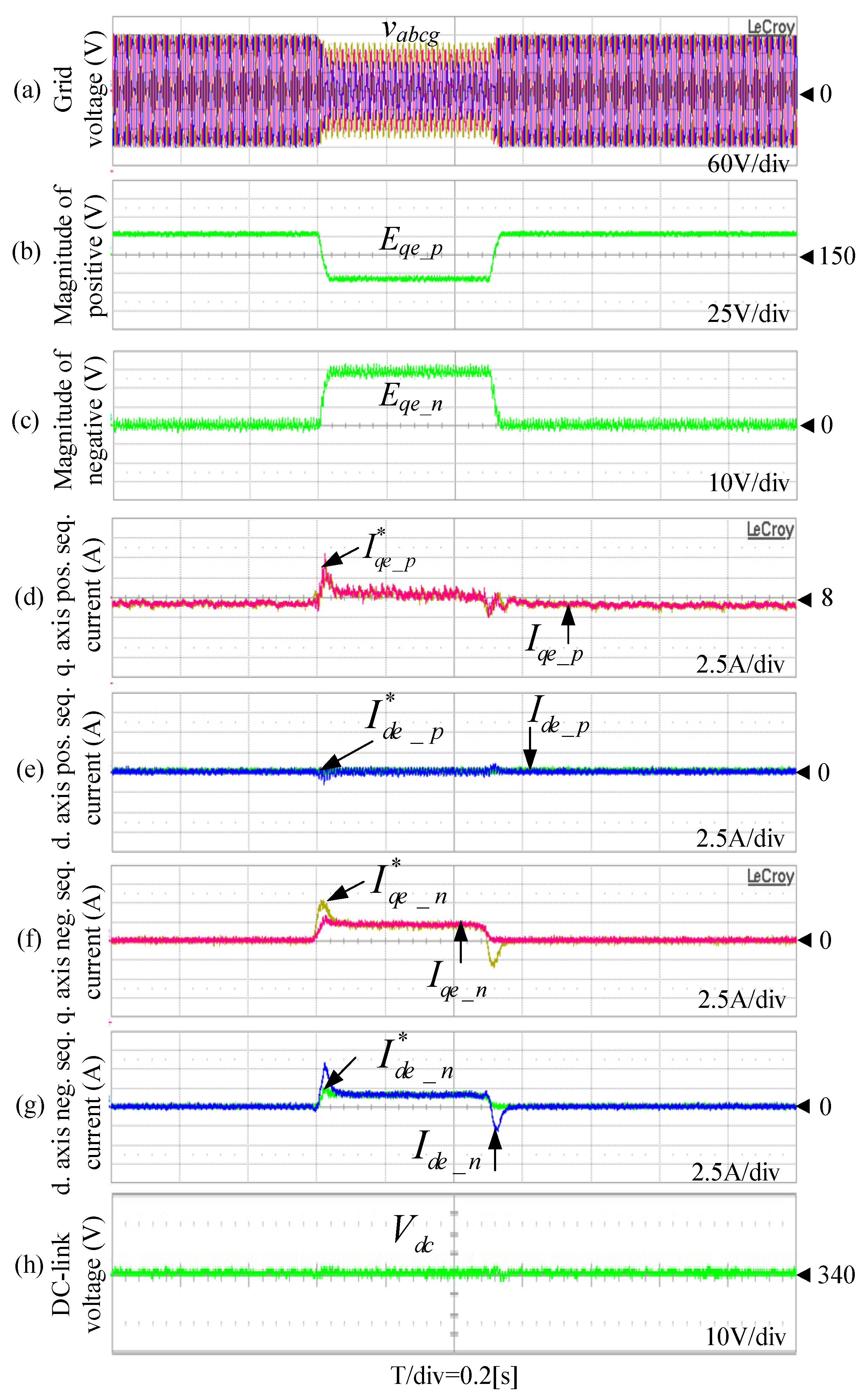
6.2. FRT Tests for an Unbalanced Voltage Sag

Firstly, the FRT capability of the WTS is investigated under the unbalanced voltage sag, where the three grid-phase voltages are reduced to 80%, 60%, and 40%, respectively, applying for the test as shown in Figure 10a–c for the phase voltages and magnitudes of its P_NSC, respectively. The control performance of the GSC is mainly demonstrated in Figure 10. From Figure 10d,e, it is known that the performance of the current controllers is good for the dq-axis grid currents of PSC, respectively, in which the actual values follow reference one well. It is apparent from Figure 10f,g the q- and d-negative-sequence grid current components exist under the unbalanced sag condition, and the performance control is good. The transients for these components appear at the beginning and the end of fault but within the allowable region. Figure 10h shows the DC-link voltage, which is kept constant at 340 V as in the normal grid condition.
A response of the turbine simulator is shown in Figure 11, which also demonstrates the turbine inertia effect. When a sag occurs, the power conversion coefficient and turbine power are decreased, as shown in Figure 11a,b, respectively, since the turbine speed is increased, as seen in Figure 11c. The power match of the whole WTS is investigated, in which the acceleration of the turbine and the operation of ESSs and BRs are activated. Due to a decrease in turbine power, where kinetic energy is stored in the system inertia, the generator power is reduced, as shown in Figure 11d. Figure 11e shows the power flowing into the grid, which is much reduced due to a deep drop in the grid voltage. The amount of mismatch power between the PMSG and network is consumed by the ESSs and BRs, where the ESSs absorb the amount of 400 W equal to its rating as shown in Figure 11f, while the rest is dissipated on the BR as shown in Figure 11g. According to Figure 11h, the EDLC voltage is increased due to charging, and the effect of ESR (equivalent series resistance) of the super-capacitor is also shown in this figure. At the beginning of voltage sag, the EDLC voltage is increased fast due to an increase in EDLC current from zero. Inversely, the EDLC voltage is decreased at the end of sag due to a decrease in EDLC current down to zero. The control performance of the ESS is also demonstrated. Figure 11i shows that the power control performance is good, in which the ESS power follows its reference closely. Under normal conditions, the ESS is deactivated where its power is zero. Figure 11j shows the boost inductor currents, which demonstrates that the controller works satisfactorily.

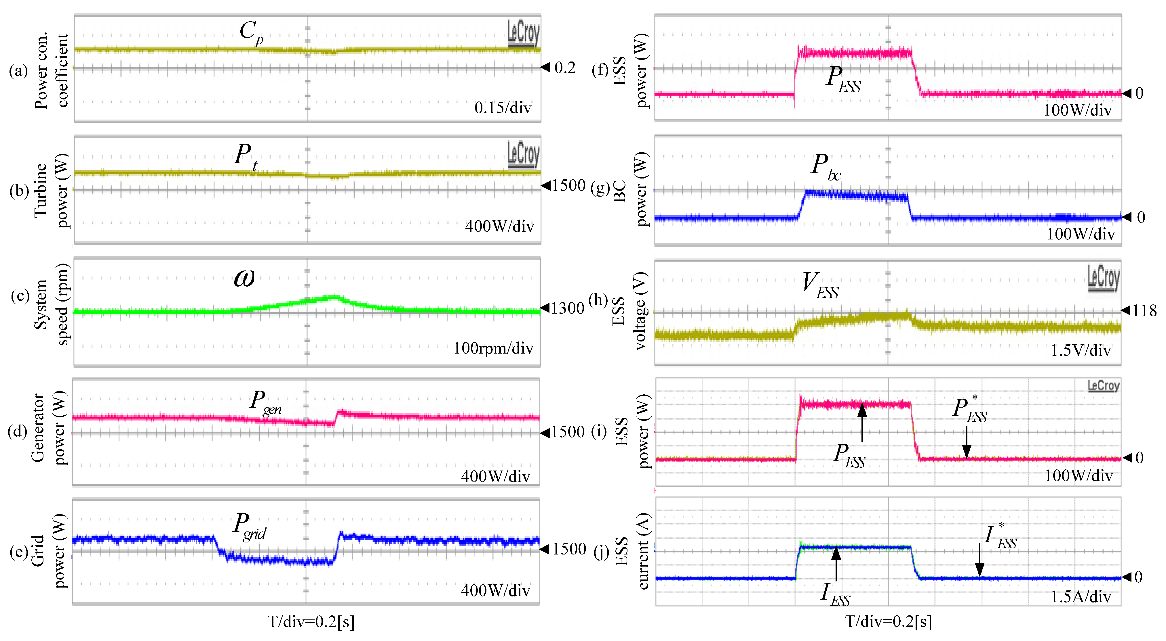
6.3. Power Fluctuation Mitigation Tests

Improvement of the output power quality of the WTS in the condition of varying wind speed is investigated in these tests. Figure 12a shows the wind speed, where its peak value is about 17% higher than the mean value of 9.5 m/s. The generator speed varies similarly to the wind speed pattern, as shown in Figure 12b. According to the MPPT control, the generator power also fluctuates as shown in Figure 12c, where the peak power is about 45% higher than the average power. It is shown in Figure 12d that the grid power can be smoothened with less than 10% variation due to the operation of the ESS and the BR to extract the fluctuated component of the generator power. When the ripple component of PMSG power exceeds the ESS rating, the BR is activated and dissipates the extra power, as illustrated in Figure 12e. As seen from Figure 12f,g, the controllers of the ESS power and current work satisfactorily, respectively. Figure 12h shows the super-capacitor voltage, which varies depending on their charging or discharging powers. Figure 12i shows the DC-link voltage, which is regulated well at 340 V.

7. Conclusions

This paper demonstrates the multiple task performance of a coordinated control scheme utilizing the hybrid of the ESS and BR for the PMSG-based WTS in distribution systems, where a fault ride-through capability under both symmetrical and non-symmetrical grid sags and output power fluctuation mitigation were achieved. Adding the BRs helps to reduce the capacity of the costly ESSs, while the performance of FRT capability is still kept well even under the most serious condition of three-phase grid voltage corruption, and the ESSs are able to perform the power smoothening. In the hybrid scheme, a trade-off between the rating of the ESSs and grid power fluctuation mitigation capacity can be made depending on the system operators, and the rating of the BRs can be further reduced when proper control of the PMSG speed is performed. The detailed experimental implementation for the laboratory-scaled PMSG-based WTS utilizing the SCIM drive as the wind turbine has been presented, where the experimental results for the FRT capability and output power fluctuation suppression have been shown to validate the effectiveness of the scheme and demonstrate the simulation results for the 2-MW PMSG-based WTS.
This work has sufficiently covered its salient objectives of applying a cost-effective scheme of the ESS and braking resistor in the PMSG-based WTS for the LVRT and power smoothing capability, but the state-of-charge and lifetime effect of the ESS has not been discussed. In further research, an optimally coordinated control scheme of the ESS with braking resistors and PMSG wind turbine will be studied, which considers the ESS lifetime and optimal power management for the whole system.

Author Contributions

Conceptualization, T.H.N. and A.N. (Asif Nawaz); methodology, T.H.N. and P.S.; software, T.H.N., A.N. (Asif Nawaz), P.S., A.N. (Ammar Natsheh), V.A. and T.L.V.; validation, T.H.N., P.S. and A.N. (Ammar Natsheh); formal analysis, T.H.N., A.N. (Ammar Natsheh) and V.A.; investigation, T.H.N., A.N. (Asif Nawaz), P.S., A.N. (Ammar Natsheh), V.A. and T.L.V.; resources, A.N. (Asif Nawaz) and P.S.; data curation, V.A. and T.L.V.; writing—original draft preparation, T.H.N.; writing—review and editing, A.N. (Asif Nawaz), P.S., A.N. (Ammar Natsheh), V.A. and T.L.V.; visualization, A.N. (Asif Nawaz), P.S. and A.N. (Ammar Natsheh); supervision, T.H.N.; project administration, T.H.N.; funding acquisition, T.H.N. All authors have read and agreed to the published version of the manuscript.

Funding

This research was funded by Higher Colleges of Technology under Interdisciplinary Grant_212294-Fund code 113166 dated 24 February 2022.

Informed Consent Statement

Not applicable.

Conflicts of Interest

The authors declare no conflict of interest.

References

  1. Huynh, P.; Tungare, S.; Banerjee, A. Maximum power point tracking for wind turbine using integrated generator-rectifier systems. IEEE Trans. Power Electron. 2021, 36, 504–512. [Google Scholar] [CrossRef]
  2. Nguyen, T.H.; Van, T.L.; Nawaz, A.; Natsheh, A. Feedback Linearization-Based Control Strategy for Interlinking Inverters of Hybrid AC/DC Microgrids with Seamless Operation Mode Transition. Energies 2021, 14, 5613. [Google Scholar] [CrossRef]
  3. Nguyen, T.H.; Quach, N.T. A hybrid HVDC converter based on M2C and diode rectifiers without DC capacitors for offshore wind farm integration. Int. J. Electr. Power Energy Syst. 2021, 133, 107260. [Google Scholar] [CrossRef]
  4. Ramasamy, T.; Abdul Basheer, A.; Tak, M.-H.; Joo, Y.-H.; Lee, S.-R. An Effective DC-Link Voltage Control Strategy for Grid-Connected PMVG-Based Wind Energy Conversion System. Energies 2022, 15, 2931. [Google Scholar] [CrossRef]
  5. Prince, M.K.K.; Arif, M.T.; Gargoom, A.; Oo, A.M.T.; Haque, E. Modeling, parameter measurement, and control of PMSG-based grid-connected wind energy conversion system. J. Mod. Power Syst. Clean Energy 2021, 9, 1054–1065. [Google Scholar] [CrossRef]
  6. do Nascimento, T.F.; Nunes, E.A.D.F.; Villarreal, E.R.L.; Pinheiro, R.F.; Salazar, A.O. Performance analysis of an electromagnetic frequency regulator under parametric variations for wind system applications. Energies 2022, 15, 2873. [Google Scholar] [CrossRef]
  7. Yuan, H.; Xin, H.; Huang, L.; Wang, Z.; Wu, D. Unified power quality conditioner with advanced dual control for performance improvement of DFIG-based wind farm. IEEE Trans. Energy Convers. 2019, 34, 838–848. [Google Scholar] [CrossRef]
  8. Luo, C.; Banakar, H.; Shen, B.; Ooi, B.T. Strategy to smooth wind power fluctuation of wind turbine generator. IEEE Trans. Energy Convers. 2007, 22, 341–349. [Google Scholar] [CrossRef]
  9. Wang, D. Utilisation of kinetic energy from wind turbine for grid connections: A review paper. IET Renew. Power Gener. 2018, 12, 615–624. [Google Scholar] [CrossRef]
  10. Carrasco, J.M.; Franquelo, L.G.; Bialasiewicz, J.T.; Galvan, E.; Guisado, R.C.P.; Prats, M.A.M.; Leon, J.I.; Alfonso, M. Power-electronic system for the grid integration of renewable energy sources: A survey. IEEE Trans. Ind. Electron. 2006, 53, 1002–1016. [Google Scholar] [CrossRef]
  11. Cardenas, R.; Asher, G.; Pena, R.; Clare, J. Power smoothing control using sensorless flywheel drive in wind–diesel generation system. In Proceedings of the IEEE 28th Annual IEEE IECON, Seville, Spain, 5–8 November 2002; pp. 3303–3308. [Google Scholar]
  12. Magnus, D.; Scharlau, C.C.; Pfitscher, L.L.; Costa, G.C.; Silva, G.M. A novel approach for robust control design of hidden synthetic inertia for variable speed wind turbines. Electr. Power Syst. Res. 2021, 196, 107267. [Google Scholar] [CrossRef]
  13. Barra, P.; de Carvalho, W.C.; Menezes, T.S.; Fernandes, R.A.S.; Coury, D.V. A review on wind power smoothing using high-power energy storage systems. Renew. Sustain. Energy Rev. 2021, 137, 110455. [Google Scholar] [CrossRef]
  14. Eydi, M.; Alishahi, M.; Zarif, M. A novel output power determination and power distribution of hybrid energy storage system for wind turbine power smoothing. IET Electric Power Appl. 2022, 1–17. [Google Scholar] [CrossRef]
  15. Gencer, A. Analysis and Control of Fault Ride Through Capability Improvement PMSG Based on WECS Using Active Crowbar System During Different Fault Conditions. Elektron. Elektrotechnika 2018, 24, 64–69. [Google Scholar] [CrossRef] [Green Version]
  16. Nasiri, M.; Arzani, A. Roust control scheme for the braking chopper of PMSG-based wind turbines—A comparative assessment. Int. J. Electr. Power Energy Syst. 2022, 134, 107322. [Google Scholar] [CrossRef]
  17. Jeong, D.H.; Kim, C.H.; Gui, Y.H.; Chung, C.C. Sliding mode control for LVRT of a PMSG wind turbine using stored energy in rotor inertia. In Proceedings of the IEEE Power and Energy Society General Meeting, Boston, MA, USA, 17–21 July 2016; pp. 1–5. [Google Scholar]
  18. Alhejji, A.; Bouzid, Y. Robust Adaptive PI Controller of Low Voltage Ride-Through For PMSG-Based Wind Turbine. In Proceedings of the 2019 6th International Conference on Control, Decision and Information Technologies (CoDIT), Paris, France, 23–26 April 2019; pp. 1233–1237. [Google Scholar]
  19. Kim, C.; Kim, W. Coordinated Fuzzy-Based Low-Voltage Ride-Through Control for PMSG Wind Turbines and Energy Storage Systems. IEEE Access 2020, 8, 105874–105885. [Google Scholar] [CrossRef]
  20. Shen, Y.-W.; Ke, D.-P.; Qiao, W.; Sun, Y.-Z.; Kirschen, D.S.; Wei, C. Transient reconfiguration and coordinated control for power converters to enhance the LVRT of a DFIG wind turbine with an energy storage device. IEEE Trans. Energy Convers. 2015, 30, 1679–1690. [Google Scholar] [CrossRef]
  21. Kim, C.; Kim, W. Low-Voltage Ride-Through Coordinated Control for PMSG Wind Turbines Using De-Loaded Operation. IEEE Access 2021, 9, 66599–66606. [Google Scholar] [CrossRef]
  22. Nguyen, T.H.; Lee, D.-C.; Song, S.-H.; Kim, E.-H. Improvement of power quality for PMSG wind turbine systems. In Proceedings of the IEEE-ECCE, Atlanta, GA, USA, 12–16 September 2010; pp. 2763–2770. [Google Scholar]
  23. Nguyen, T.H.; Lee, D.-C. Advanced fault ride-through technique for PMSG wind turbine systems using line-side converter as STATCOM. IEEE Trans. Ind. Electron. 2013, 60, 2842–2850. [Google Scholar] [CrossRef]
  24. Lubosny, Z. Wind Turbine Operation in Electric Power System; Springer-Verlag: Berlin/Heidelberg, Germany, 2003; Chapter 5. [Google Scholar]
  25. Shaker, M.S.; Kraidi, A.A. Robust fault-tolerant control of wind turbine systems against actuator and sensor faults. Arab. J. Sci. Eng. 2017, 42, 3055. [Google Scholar] [CrossRef]
  26. Akhmatov, V. Induction Generators for Wind Power; Multi-Science Publishing Company: Essex, UK, 2005; Chapter 3. [Google Scholar]
  27. Jang, J.-I.; Lee, D.-C. High performance control of three-phase PWM converters under non-ideal source voltage. In Proceedings of the IEEE ICIT, Mumbai, India, 15–17 December 2006; pp. 2791–2796. [Google Scholar]
  28. Song, H.-S.; Nam, K. Dual current control scheme for PWM converter under unbalanced input voltage conditions. IEEE Trans. Ind. Appl. 1999, 46, 953–959. [Google Scholar]
  29. Rodriguez, P.; Pou, J.; Bergas, J.; Candela, J.I.; Burgos, R.P.; Boroyevich, D. Decoupled double synchronous reference frame PLL for power converters control. IEEE Trans. Power Electron. 2007, 22, 584–592. [Google Scholar] [CrossRef]
  30. Rodriguez, P.; Luna, A.; Aguilar, R.S.M.; Otadui, I.E.; Teodorescu, R.; Blaabjerg, F. A stationary reference frame grid synchronization system for three-phase grid-connected power converters under adverse grid conditions. IEEE Trans. Power Electron. 2012, 27, 99–112. [Google Scholar] [CrossRef]
  31. Ibrahim, A.O.; Nguyen, T.H.; Lee, D.-C.; Kim, S.-C. A fault ride-through technique of DFIG wind turbine systems using dynamic voltage restorers. IEEE Trans. Energy Convers. 2011, 26, 871–882. [Google Scholar] [CrossRef]
  32. Fernández, G.; Martínez, A.; Galán, N.; Ballestín-Fuertes, J.; Muñoz-Cruzado-Alba, J.; López, P.; Stukelj, S.; Daridou, E.; Rezzonico, A.; Ioannidis, D. Optimal D-STATCOM Placement Tool for Low Voltage Grids. Energies 2021, 14, 4212. [Google Scholar] [CrossRef]
  33. Sul, S.-K. Control of Electrical Machine Drive Systems; Wiley: Hoboken, NJ, USA, 2011. [Google Scholar]
  34. Data, R.; Ranganathan, V.T. A method of tracking the peak power points for a variable speed wind energy conversion system. IEEE Trans. Energy Convers. 2003, 18, 163–168. [Google Scholar] [CrossRef]
  35. Sharma, S.; Chandra, A.; Saad, M.; Lefebvre, S.; Asber, D.; Lenoir, L. Voltage flicker mitigation employing smart loads with high penetration of renewable energy in distribution systems. IEEE Trans. Sust. Energy 2017, 8, 414–424. [Google Scholar] [CrossRef]
  36. Camara, M.B.; Gualous, H.; Gustin, F.; Berthon, A. Design and new control of DC/DC converters to share energy between supercapacitors and batteries in hybrid vehicles. IEEE Trans. Veh. Tech. 2008, 57, 2721–2735. [Google Scholar] [CrossRef]
  37. Wang, J.; Xiong, X.; Li, H.; Lu, X. Time-periodic model of wind speed and its application in risk evaluation of wind-power-integrated power systems. IET Renew. Power Gener. 2019, 13, 46–54. [Google Scholar] [CrossRef]
  38. Available online: https://www.amazon.ae/Maxwell-DuraBlue-Capacitor-3000farad-ultracapacitor/dp/B081LBMNH2/ref=sr_1_4?crid=S8K48G97H0M1&keywords=super+capacitor&qid=1665136325&qu=eyJxc2MiOiI0LjQyIiwicXNhIjoiMy43NSIsInFzcCI6IjAuMDAifQ%3D%3D&sprefix=supercapacito%2Caps%2C234&sr=8-4 (accessed on 8 October 2022).
  39. Available online: https://ae.wiautomation.com/siemens/drives-motors-circuits-protection/sinamics/6SL30001BE313AA0?utm_source=shopping_free&utm_medium=organic&utm_content=AE50617&gclid=Cj0KCQjwnP-ZBhDiARIsAH3FSReMDOWHKVbC6VEdM0KUlGzyPw3MqflDOLICsMR2KF62a50nwJ3P2EwaAngdEALw_wcB (accessed on 8 October 2022).
  40. Texas Instruments. TMS320C3x User’s Guide; Texas Instruments: Dallas, TX, USA, 1997. [Google Scholar]
Figure 1. WTS with PMSG utilizes a hybrid scheme of ESSs and BRs in the distribution system [17].
Energies 15 08282 g001
Figure 2. The control scheme of GSC [27,28].
Energies 15 08282 g002
Figure 3. The control scheme of PMSG.
Energies 15 08282 g003
Figure 4. Power and current controllers of the ESSs and the braking chopper operation.
Energies 15 08282 g004
Figure 5. GSC performance at unbalanced voltage dip. (a) Grid phase voltages. (b) The DC-link voltage of B2B converters. (c) NSC d-axis currents. (d) NSC q-axis currents. (e) PSC d-axis currents. (f) PSC q-axis currents.
Energies 15 08282 g005
Figure 6. Control performances of the PMSG, ESS, and BRs at the fault. (a) WTS speed. (b) Grid and PMSG powers. (c) d-axis components of PMSG current. (d) q-axis components of PMSG current. (e) ESS powers. (f) EDLC currents. (g) EDLC voltage. (h) Current of BRs.
Energies 15 08282 g006
Figure 7. Power fluctuation mitigation performance. (a) Wind velocity pattern. (b) PMSG speed. (c) d-axis grid currents. (d) q-axis grid currents. (e) DC-link voltages. (f) d-axis currents of PMSG. (g) q-axis currents of PMSG. (h) Generator and grid powers. (i) ESS power. (j) EDLC current. (k) EDLC voltage. (l) BR current.
Energies 15 08282 g007
Figure 8. Experimental setup. (a) Configuration. (b) Apparatus.
Energies 15 08282 g008
Figure 9. Gate pulse generation scheme based on the DSP and EPLD.
Energies 15 08282 g009
Figure 10. Performance of the grid-side converter at unbalanced voltage dip. (a) Grid phase voltages. (b) The magnitude of PSC. (c) The magnitude of NSC. (d) q-axis currents of PSC. (e) d-axis currents of PSC. (f) q-axis currents of NSC. (g) d-axis currents of NSC. (h) The DC-link voltage of B2B converters.
Energies 15 08282 g010
Figure 11. Response of WTS under unbalanced sag. (a) Power coefficient. (b) Turbine power. (c) Turbine speed. (d) PMSG power. (e) Power flows into the grid. (f) Power charging to EDLC. (g) Power consuming by BRs. (h) EDLC voltage. (i) Power controller. (j) Current controller.
Energies 15 08282 g011
Figure 12. Power fluctuation mitigation for varying wind velocity. (a) Wind velocity. (b) Generator speed. (c) PMSG power. (d) Power flows into the grid. (e) Power of BRs. (f) Power of supercapacitor. (g) Supercapacitor current. (h) Voltage of supercapacitor. (i) DC-link voltage.
Energies 15 08282 g012
Table 1. Cost comparison of the ESS only and hybrid scheme.
SystemOnly ESSHybrid Scheme
Specification ESSBraking Resistor
Power rating2 MW0.6 MW1.4 MW
Unit rating4.8 kW [38]4.8 kW [38]125 kW [39]
Unit price$526 [38]$526 [38]$1145 [39]
Number of units41712512
Total cost$219,342$79,490
Table 2. Specifications of turbine and PMSG.
ParametersValues
Power rating2 MW
Turbine rotor radius42 m
Turbine inertia constant4.2 s
Generator voltage690 V
Resistance/inductance8.56 mΩ/3.59 mH
Number of pole pairs60
Generator inertia0.75 s
Table 3. Specifications of ESS and BR.
ParametersValues
Ratings 6.37 MJ/0.6 MW
Capacitance of EDLC200 F
Inductor (Lf)0.5 mH
Operating voltage (VESS)0.4 kV
Pbc-rated1.133 MW
Rbc1.49 Ω
Table 4. Specifications of PMSG, ESSs, and BRs.
ParametersValues
Power rating2.68 kW
Number of pole pairs3
Speed rating1200 rpm
Inertia of WTS0.071 kg.m2
Stator resistance/inductance0.49 Ω /5.35 mH
Boost inductance3.17 mH
Capacitance of ESSs2.92 F
Operating voltage120 V
BR resistance23 Ω
Table 5. Controller gains for the experimental system.
Converters and ControllersGains
GSCDC-link voltage controller K p v c = 0.605     and     K i v c = 44.1
Current controllers K p c c = 2.7     and     K i c c = 430
MSCSpeed controller K p s c = 1.052     and     K i s c = 8.42
Current controllers K p c c = 2.41     and   K i c c = 220.5
DC/DC converterPower controller K p p c = 0.005     and     K i p c = 0.472
Current controller K p c c = 2.67     and     K i c c = 1141.2
Publisher’s Note: MDPI stays neutral with regard to jurisdictional claims in published maps and institutional affiliations.

