Article

Interaction between Droplets and Particles as Oil–Water Slurry Components

Heat Mass Transfer Laboratory, National Research Tomsk Polytechnic University, 634050 Tomsk, Russia
*
Author to whom correspondence should be addressed.
Energies 2022, 15(21), 8288; https://doi.org/10.3390/en15218288
Submission received: 23 September 2022 / Revised: 24 October 2022 / Accepted: 3 November 2022 / Published: 6 November 2022

Abstract

:
The characteristics of the collisions of droplets with the surfaces of particles and substrates of promising oil–water slurry components (oil, water and coal) were experimentally studied. Particles of coals of different ranks with significantly varying surface wettability were used. The following regimes of droplet–particle collisions were identified: agglomeration, stretching separation and stretching separation with child droplets. The main characteristics of resulting child droplets were calculated. Droplet–particle interaction regime maps in the B = f(We) coordinates were constructed. Equations to describe the boundaries of transitions between the droplet–particle interaction regimes (B = nWek) were obtained. The calculated approximation coefficients make it possible to predict threshold shifts in transition boundaries between the collision regimes for different fuel mixture components. Differences in the characteristics of secondary atomization of droplets interacting with particles were established. Guidelines were provided on applying the research findings to the development of technologies of composite liquid fuel droplet generation in combustion chambers with the separate injection of liquid and solid components, as well as technologies of secondary atomization of fuel droplets producing fine aerosol.

1. Introduction

High concentrations of the main gaseous anthropogenic emissions (oxides of sulfur, nitrogen and carbon) are key air pollutants in regions with active combustion of coal and coal processing waste [1,2,3]. The economic and energy benefits of solid fuels contribute to their strong position in the global energy sector, thus worsening the environmental problems [1,4]. Some countries (China, India, Japan, Germany, France, the USA, etc.) have placed severe restrictions on the rates of direct combustion of coal [5,6,7]. It is a relevant task to optimize coal combustion to maintain minimal negative impact on the environment. Coal pyrolysis and gasification [8,9,10], as well as combustion in the form of slurries [11,12,13] are generally accepted as the most promising approaches to the corresponding tasks. The slurries in question are often referred to as coal–water slurries with or without petrochemicals. The economic indicators of technologies relying on coal pyrolysis and gasification are not very high at the moment [14,15]. This prevents their wide application in the economy of most countries concerned [14,16]. The combustion of coal and coal processing waste in the slurry fuel composition is generally considered promising [12,17,18]. Comprehensive studies [19,20,21] taking the environmental, economic, energy and social indicators into account justify the potential of these fuels compared to different solid and liquid fuels (fuel oil, coal, slime, filter cake, etc.) and, under certain conditions, to natural gas [22,23].
Yet the technologies of combustion of composite fuels containing coal particles and coal processing waste present some challenges that have not been adequately addressed so far. One of these challenges is stable (in terms of the flow rate and resulting droplet distributions) spraying of slurries with nozzles [17,24]. Nozzles come with different modifications [25,26,27]. The need for a longer service life of nozzles calls for developing new designs that minimize the effect of flow channel clogging with solid particles, wear of wall materials due to friction with solid particles and instability of the fuel component composition. Tackling each of the formulated problems necessitates considerable financial investments. At the same time, these difficulties can be overcome by injecting slurry fuel components (e.g., coal particles, water and oil droplets) separately into combustion chambers. There are not enough data now on what collision regimes of slurry fuel components (droplets and particles) occur in combustion chambers when they are fed separately. The modern theory of the droplet–particle interaction, whose main postulates are presented in the review [28], is still unable to reliably and efficiently predict the conditions of the fuel component (particles and droplets) agglomeration and the conditions of their separation that forms an aerosol cloud. Moreover, the number of components mixing in a combustion chamber may not be limited to just two. Therefore, it is an important task to experimentally study the collision regimes and outcomes of droplets and particles of promising slurry fuel components.
Previous research findings [29,30,31] indicate that the main components of promising slurry fuels are coals of different ranks, water and combustible liquids (such as various industrial oils, namely, turbine, transformer, motor, castor, etc.). The studies [32,33,34] present the experimental results illustrating significant differences in the interaction regimes of different slurry fuel component droplets colliding with each other in gas. The sequence of the interaction of component droplets and their role (projectile, target) was found to be of crucial importance. Regime maps were plotted, and secondary fragment characteristics (number, size, velocities, energy, pulses, etc.) were calculated. These highlight the high potential of substantial secondary atomization of slurry fuel droplets as a result of their collisions. The process is essential to the intensification of ignition of water-containing slurry fuels because their combustion starts with a considerable delay (due to a high heat of vaporization and heat capacity of water). So far, neither the collision regime maps of comparably sized fuel droplets and particles nor their collision outcomes have been studied. Consequently, it is important to explore the binary collisions between the droplets and particles. The present-day ideas of such processes are based on the experimental results for model liquids and particles [35], in particular, water, alcohols, metal and sapphire particles, whose main properties differ greatly from those of slurry fuel components. As a result, it is difficult to predict the conditions of fuel component interaction using the data [35]. Mathematical modeling results for the motion of fuel components in furnaces were generally [36] obtained when using the following promising [37,38,39] materials and substances: biomass, coal processing waste, low-rank and brown coals, and peat. The motivation of this study is to identify the conditions for generating two- and three-component fuel droplets in combustion chambers when feeding the particles of coal and coal processing waste separately from the droplets of combustible and noncombustible liquid components.
The purpose of this study is to construct the collision regime maps for droplets and solid particles of promising oil–water slurry components, when using different sequences of their interaction and ambient conditions corresponding to fuel technologies. It is interesting to explore the possibility of forming two- and three-component child droplets when several solid particles and liquid droplets collide in different regimes.

2. Materials and Methods

2.1. Materials

The main liquids considered in the experiments were distilled water and used motor oil. The properties of these liquids are similar to those used in composite fuel preparation technologies [40,41,42]. Adding oil to composite fuels increases their calorific value, which is lower than that of coal as a result of adding water. The properties of liquids are listed in Table 1.
The ranks of coals used as solid substances were chosen from the most common ones in composite liquid fuel preparation [17,25,43]: brown and coking bituminous coal, filter cake of coking bituminous coal and anthracite. One of the key characteristics of solid substances interacting with liquids is their wettability [44]. The hysteresis of the wettability of coal particles is significantly affected by their surface uniformity, roughness and chemical purity. Wetted coal particles have gas cavities in the surface pores and cracks. These also affect the dynamics of interaction with liquid droplets [45]. With such cavities, the stain of the contact of liquid with a coal particle is much smaller than in the case of the surface without pores. The gas cavities in the surface defects of coal particles are the points of stress concentration on the liquid surface. Using shadowgraphy [46], the wettability properties of the materials under study were determined. The data in Table 2 are based on the results of measuring the contact angle of pressed pellets from particles of the above ranks of coal ground to 60 µm and their monolithic processed fragments. The contact angle of monolithic fragments of filter cake is difficult to measure reliably. Due to its high porosity, the droplet did not remain on the surface. It soaked into the near-surface layer.
The methods of slurry preparation, storage, transportation and spraying used in industrial applications have certain disadvantages. During primary atomization in combustion chambers, emulsions and slurries tend to separate into components (namely, the water film separates) [17,47]. The methods of preparing emulsions and slurries and maintaining their stable state for a long time require their occasional mixing or adding specialized additives (stabilizers). The combustion of such additives together with a fuel often has a negative environmental impact. Therefore, it is important to intensify the secondary atomization of fuel droplets in combustion chambers through their collisions with each other and with solid particles.

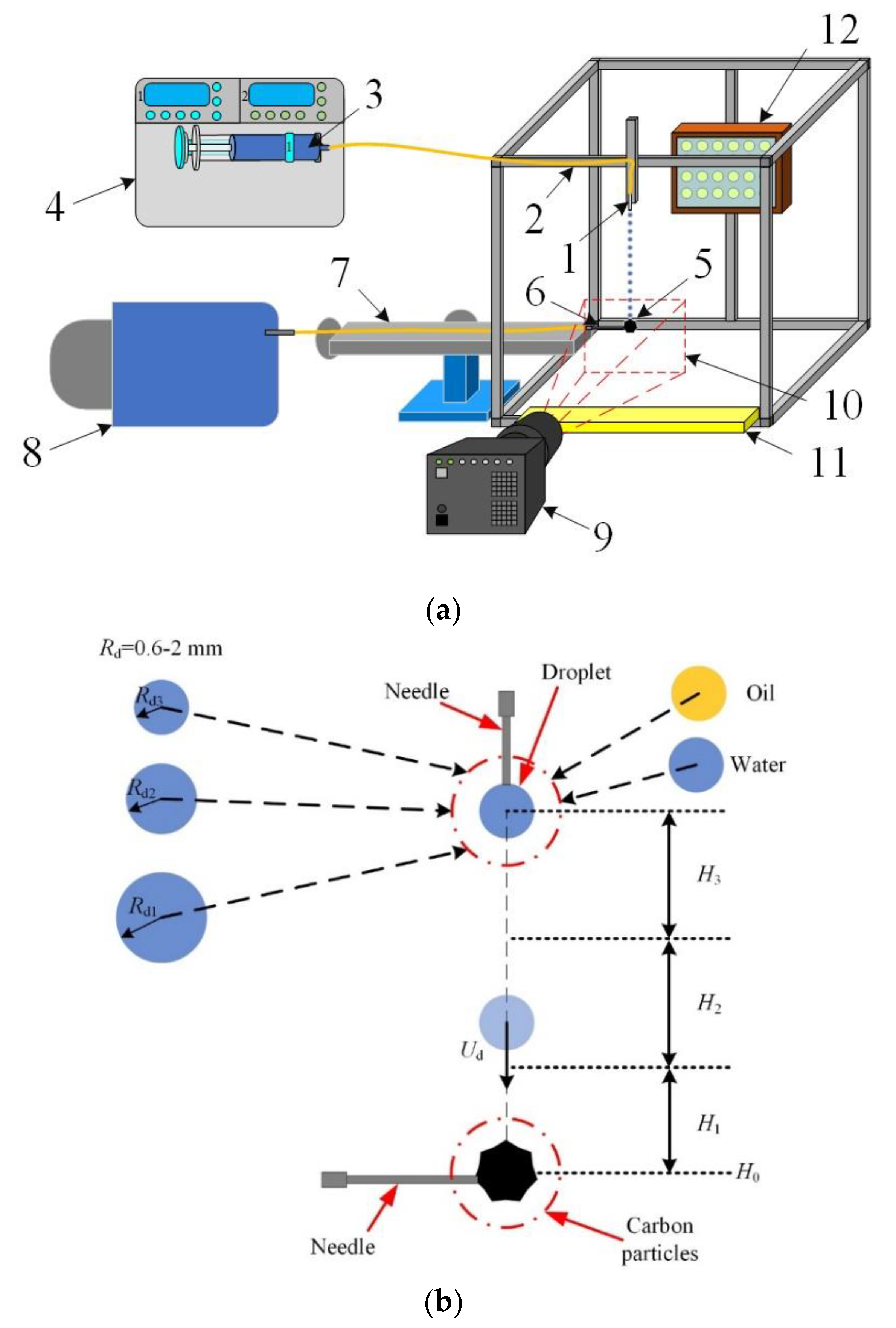
2.2. Setup and Experimental Procedures

The study of the characteristics of interactions between the droplets and particles of promising oil-water emulsion components was conducted employing a setup shown in Figure 1. The setup included a vacuum pump to hold a solid particle, a droplet dispenser and a system of high-speed video recording with appropriate illumination. The load-bearing structure was made up of aluminum beams with mortises to fit additional equipment. The structure profile allowed high-accuracy control of the position of the setup elements relative to each other. Used motor oil was fed through detachable nozzles (2) with different internal diameters (0.21–1.12 mm). The nozzles were mounted vertically above the experimental sample. The liquid was ejected to the nozzles with a 50-mL syringe (3). The pressure in the liquid supply duct was built up with a syringe pump (4) maintaining a constant flow rate of 80 mL/h. A coal particle (5) was held at the outlet of the nozzle (6) connected with copper tubes (7) to the vacuum pump (8) with a flow rate of 70 l/h. The vacuum pump generated a pressure of 5 Pa, sufficient to hold coal particles in place when they were hit by a droplet. The diameter of the inner duct of the nozzle-holder was chosen depending on the size of particles in the range of 0.1–0.5 mm. The coal particle size Rp was varied between 0.1 and 1.5 mm. Droplet collisions with carbonaceous particles were recorded with a Photron mini UX100 video camera (9) with a frame rate of 6400 frames per second and resolution of 1280 × 720, coupled with a Sigma 105 mm 1:2.8 DG MACRO HSM lens. The recording area (10) was organized to adequately track the initial parameters of droplet movement and parameters of secondary fragments resulting from the collisions with carbonaceous particles. A container (11) was placed in the lower part to collect liquid after the collision. An LED spotlight (12) (General Lighting GOFL-30-IP65-6500) illuminated the recording area.
The key parameters of generated droplets are the radius (Rd = 0.9–2.2 mm) and resultant impact velocity (Ud = 0.5–4.0 m/s). In this size range, the droplet has a stable shape during its movement in gas. The droplet velocity range was chosen so that different collision regimes (agglomeration and stretching separation) occurred. Figure 1b presents a scheme proposed for the mixing of components of coal–water slurries containing petrochemicals (CWSP), injected separately into a combustion chamber. Using this scheme of supplying CWSP components, it is possible to avoid typical problems arising when ready-made composite fuels are injected [17,24,47].
The collisions of liquid droplets (water, oils, fuel oil, diesel fuel, etc.) with coal particles examined in this study are similar to the primary collisions in a furnace (droplet and particle size 0.1–3 mm, velocities 0.1–300 m/s, and impact angles 0–90°). The experiments involved the collisions of water and oil droplets with dry particles and particles that had been wetted with water and oil droplets. The droplets did not interact with the fixed particle before the collision. The collisions of a single liquid droplet with a particle or substrate were considered. A container to collect liquid was fit between the nozzle and particles. As soon as the droplet generation frequency and sizes became constant, the positioning mechanism moved the container aside to allow the movement of droplets to the particle. Several collisions of droplets with particles were captured on video. Yet for processing, only the first collision was used, because, in the subsequent collisions, some liquid remained on the particle. Lin et al. [48] found that the characteristics of droplet collisions with wetted particles may differ from those with dry ones. Therefore, cases were also considered when droplets collided with particles wetted with liquids, which reproduced the conditions when another droplet or several droplets collided with coal fragments. In the first case, a cover with a container for collecting liquid was fitted between the coal particle fixed on the vacuum holder and free-falling oil droplets. The cover was opened the moment the video recording began, and the collision of an oil droplet with a dry coal particle was recorded. In the second case, one 5-mL liquid droplet was poured out on the coal particle with a dropping bottle before the start of video recording. This is comparable to the volume of droplets generated by detachable nozzles.
Two regimes of droplet–particle interaction were identified when processing the recordings: agglomeration and stretching separation. Agglomeration is characterized by the deposition of a droplet on a coal particle and enveloping its surface. Stretching separation is when the liquid and the coal particle separate to produce one or several secondary fragments referred to as child droplets.
Droplet collisions are generally described by dimensionless parameters. The regime (agglomeration, stretching separation) maps were plotted allowing for the linear impact parameter and the Weber number. To take the centricity of a droplet–particle collision into account, the dimensionless linear impact parameter (B = b/(Rd + Rp) was used, where b is the linear approach parameter, and Rd and Rp are the radii of the droplet and particle, respectively. The Weber number (We = 2·ρ·Rd·Ud2/σ, where ρ is the liquid density, Ud is the droplet velocity and σ is surface tension) represents the ratio of the inertia of liquid to its surface tension. This coordinate system on the collision regime maps was chosen to take the liquid surface tension, droplet sizes and relative velocities into account. The Weber number was varied from 1 to 100 and was calculated taking the resultant (relative) velocity of droplets into account. Regime maps in the B(We) coordinate system (as in [35]) were constructed. After that, the terminal or boundary points characterizing each regime of the droplet–particle interaction were determined to plot their boundaries. The value of b is the linear approach parameter. It was calculated as a distance between the centers of mass of the droplet and particle. The way it was determined is shown graphically in Figure 2. The value of b was varied in the experiments in the ranges that corresponded to the dimensionless linear impact parameter (B) variation from 0 to 1.
The characteristics of secondary droplets resulting from the disruption of the initial droplet were examined. For that, the radii (rd) and number (Nti) of all the visible (i.e., within the recording area) secondary fragments were measured. The volume of the initial droplet was calculated: V0 = 4·π·(Rd13 + Rd23)/3. The total volume of a group of resulting child droplets was given by V1 = 4·π·Σrdi3/3. The difference between these volumes was the volume of liquid remaining on the particle surface.

3. Results

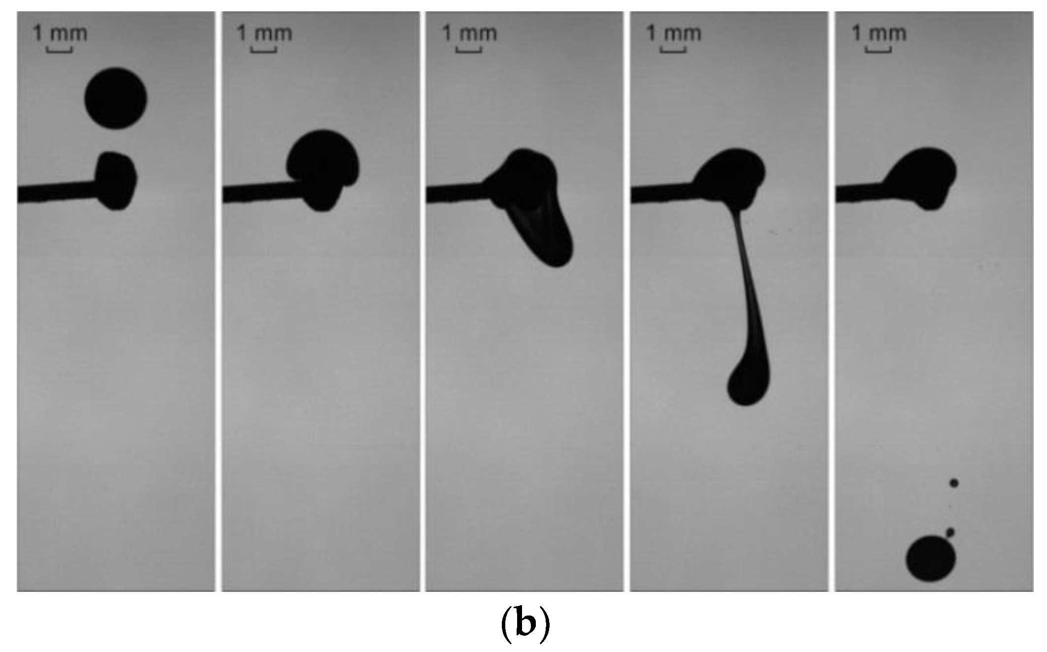
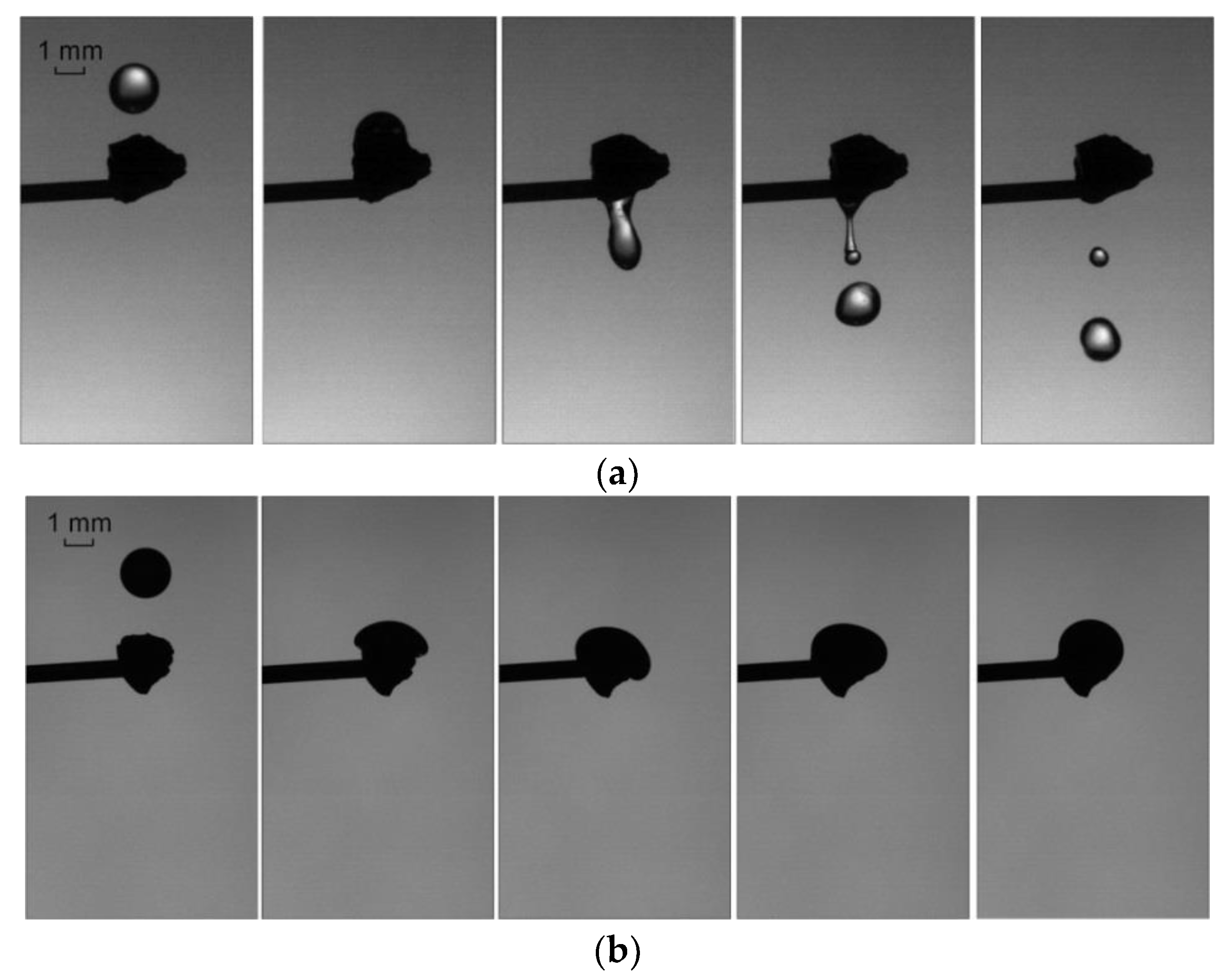
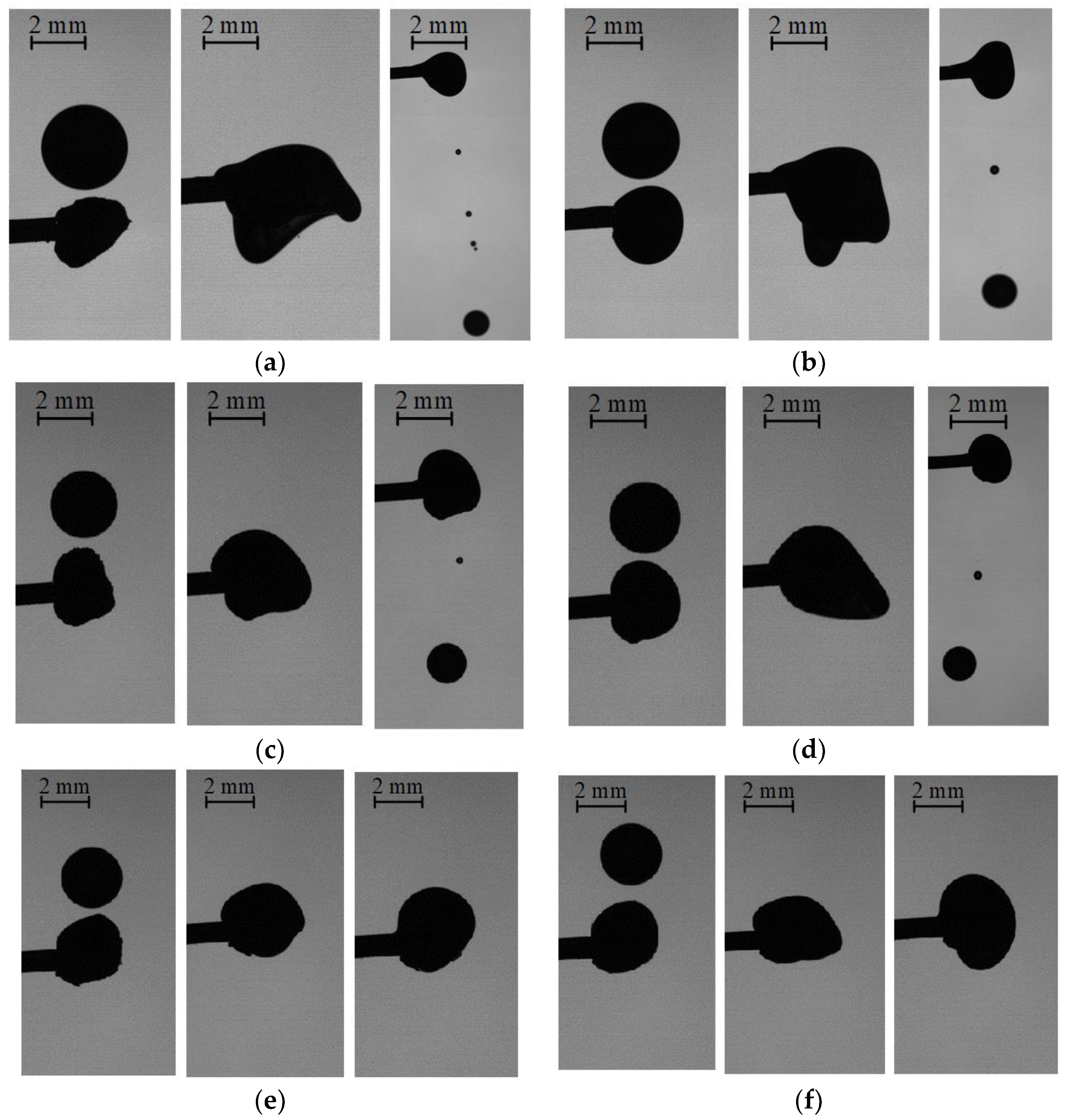
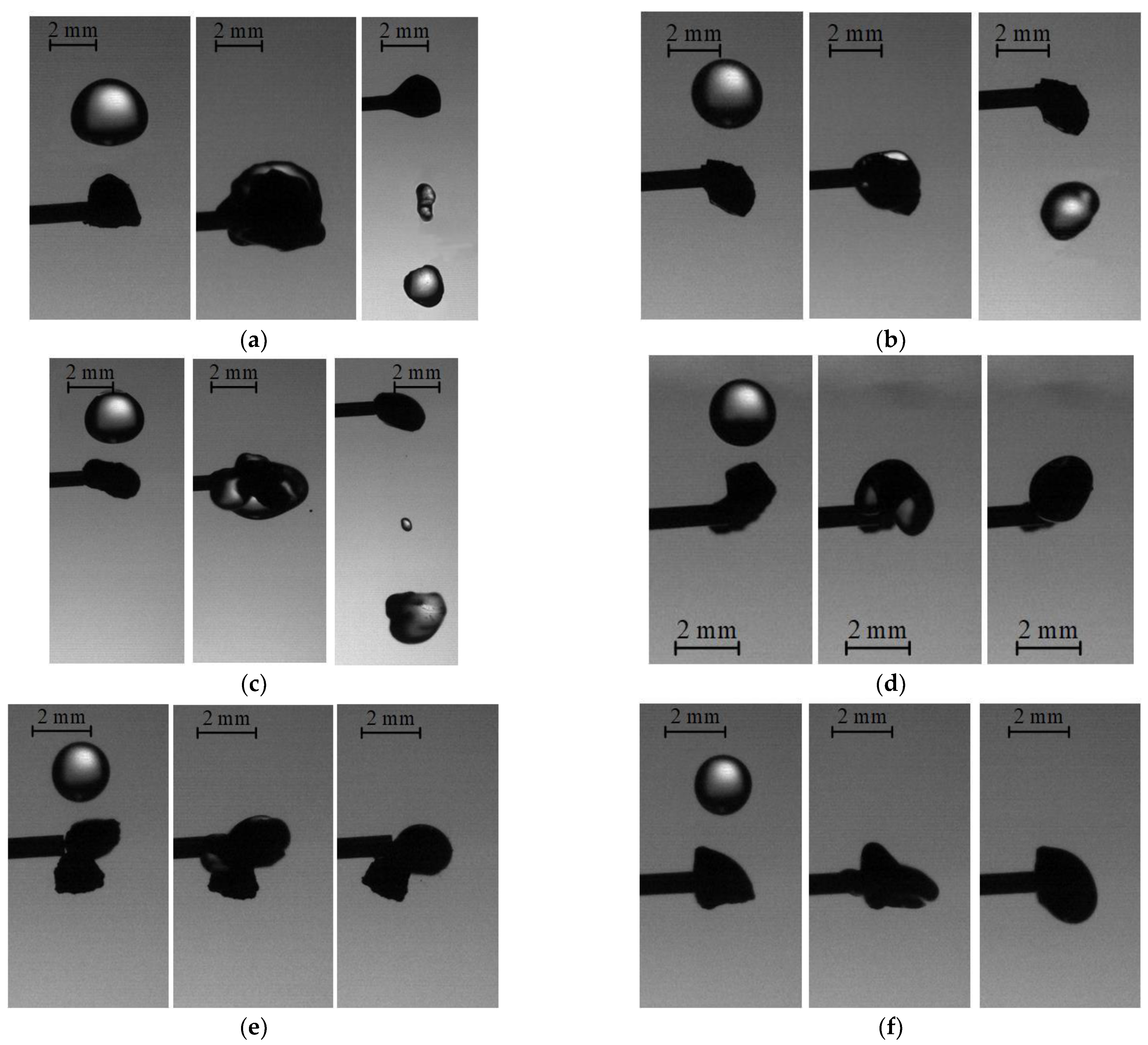
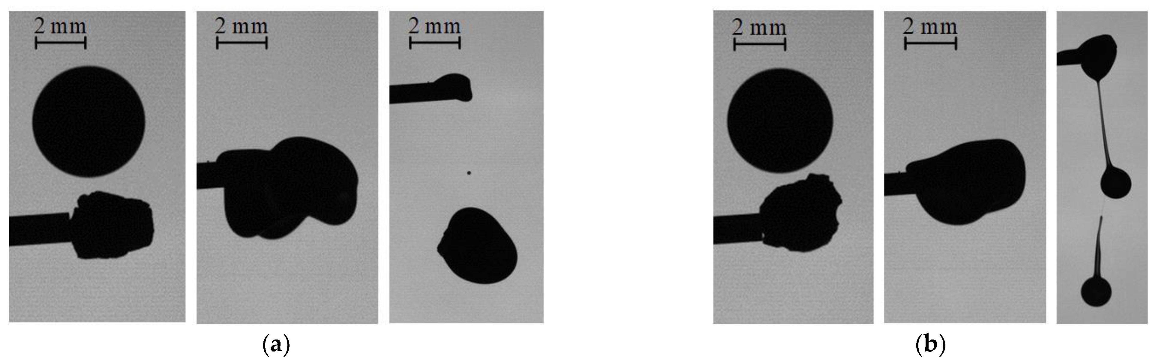
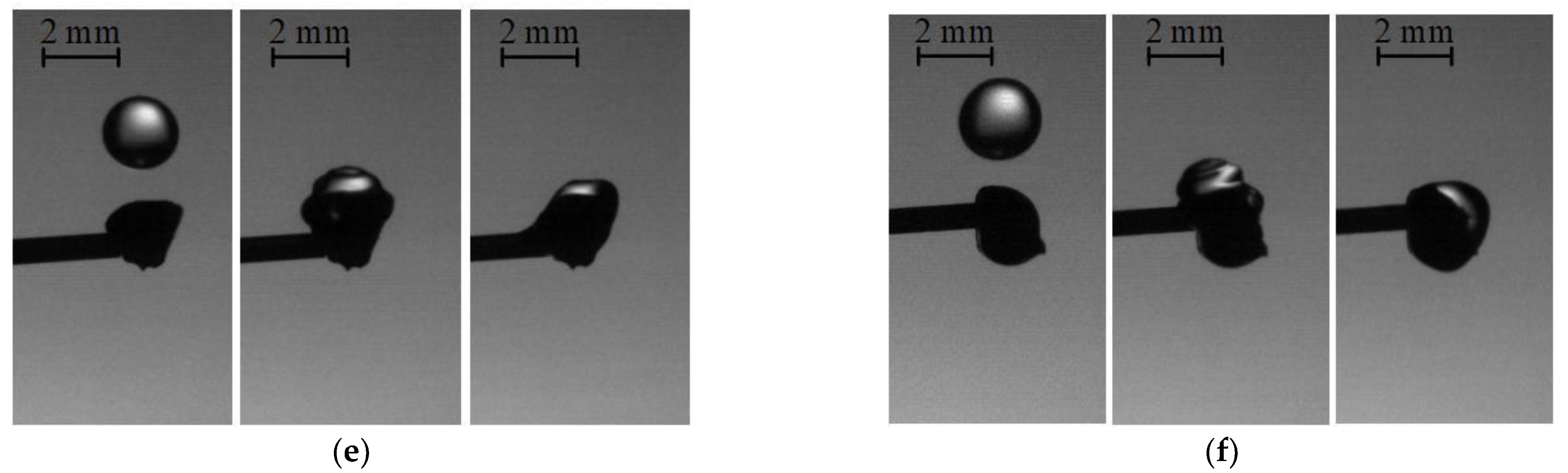
3.1. Collisions of Liquid Droplets with Solid Particles

In the experiments, the main patterns of the interaction of liquid droplets with solid particles (being the components of promising composite fuels) were established. Figure 3 and Figure 4 present typical images of the collisions of water and oil droplets of different initial sizes (Rd = 1–2.2 mm) with the carbonaceous particles of coking coal filter cake with Rp = 0.75–1.5 mm (for a series of varying droplet sizes). The images show that the key parameter affecting the occurrence of stretching separation and formation of child droplets at an identical velocity is the particle–droplet size ratio (Δ). Stretching separation proceeded when the kinetic energy of the liquid droplet movement was greater than the sum of energies used to overcome viscous friction, dissipation energy, rotational energy and the energy used to overcome the surface tension forces. If the kinetic energy was greater than the sum of energies, the liquid fragments separated from the solid particle. Otherwise, the liquid droplet remained on the solid particle (agglomeration was recorded). It is clear from Figure 3a,b that at a liquid droplet size Rd of 1.45 mm, stretching separation is bound to occur after the collision with carbonaceous particles with a size Rp of 0.75–0.9 mm. The collisions of such droplets with dry particles resulted in the formation of several child droplets. With a reduction in the initial droplet size Rd to 1.1 mm (Figure 3a,b), agglomeration was recorded. Here the droplet stuck to the carbonaceous particle and enveloped it. The liquid layer was not detached. Agglomeration occurred irrespective of whether the particle surface was dry or wet. Agglomeration was recorded both for dry and wetted particles. This result is extremely important for the technologies of composite fuel droplet preparation, since coals have different moisture content, and particles can be wetted using different methods.
Figure 3a and Figure 4a demonstrate how the interaction regimes and formation of different numbers of secondary fragments are correlated with the liquid properties. When droplets interacted with coal particles at Δ < 2, the droplet separated from the particle in the majority of the experiments. This indicates that for consistent agglomeration of a water droplet with a coal particle, the latter has to be at least twice as big as the former. Such patterns are true for low resultant (relative) velocities of objects. With an increase in the velocity of droplets Ud > 2.5 m/s by increasing the height from which they are dispensed, stretching separation was recorded.
Used motor oil droplets with a high viscosity stuck to dry coal particles (Figure 3b and Figure 4b), forming local clusters of liquid in the form of a film of uneven thickness on their surface. High viscosity and a relatively small volume of oil prevented the formation of a liquid film of even thickness on the particle surface. When used motor oil droplets collided with wetted coal particles, the oil droplet spread over the particle more evenly due to the existing oil film. This created a dense near-surface liquid layer. In a high-temperature gas environment, corresponding to combustion chambers, the oil will be the first to ignite. Coal particles will interact with the oxidizer in a high-temperature gas environment only after the oil partially burns out. These conditions offer great potential for the combustion of compositions based on coals of very different ranks characterized by ignition delays.
The experiments [35,50] also showed that the droplet–particle size ratio has a decisive effect on the collision regime. An assumption was made that the size of a droplet has a significant effect on the outcomes of its interaction with a particle at a constant ratio of their sizes. With an increase in the droplet volume, the ratio of surface tension to inertia decreases. Figure 5 presents typical images of the collisions of distilled water droplets with anthracite particles when varying Rd. The main parameter affecting the occurrence of stretching separation and child droplet formation at a constant velocity is the size of the initial droplets. Agglomeration, however, was recorded during the collisions between water droplets and anthracite particles at a droplet radius Rd of 1.3 mm or smaller.
Figure 4, Figure 5, Figure 6, Figure 7 and Figure 8 demonstrate the mutual influence of the shape of coal particles and the size of droplets on the characteristics of interaction regimes. The image processing revealed that droplet contact with coal particles having a smooth face resulted mostly in agglomeration. In this case, the liquid spread evenly on the particle surface. When a droplet landed on a coal particle with a sharp edge, the liquid spread along its sloping faces. This pattern was recorded for the whole range of droplet and coal particle sizes.
It is also clear from Figure 4, Figure 5, Figure 6, Figure 7 and Figure 8 that the number of child droplets emerging after the collision of a droplet with wetted coal particles decreased compared to when it collided with a dry particle, both in the case of water and oil. The obtained findings confirm a hypothesis that a preliminary layer of liquid on the solid particle surface contributes to the retention of the subsequently falling droplet. The liquid film slows down the droplet due to viscosity and surface tension forces. At low Weber numbers (We < 6 for water and We < 13 for used motor oil), the droplet agglomerates with a wetted fragment. Following the analysis of the obtained images, it was established that when composite fuels are produced by separate injections of liquid and solid components, the Weber numbers have to be low. This is possible at low velocities (<1 m/s) of the fuel components when they collide at an angle, or at higher velocities (1–2.5 m/s) when coal fragments and liquid droplets move in the same direction.
Additional experiments were performed to study the interaction of a motionless droplet with moving solid particles. Typical videograms of the collision are presented in Supplementary Materials (Videos S1 and S2). The results of the conducted experiments indicate that at relatively high droplet-to-particle size ratios (Rp > 0.4 Rd) and their low velocities (<1 m/s), a particle impinging on a droplet sticks to its surface but does not penetrate its deep layers (elastic collision is recorded). This can be explained by the fact that surface tension (molecular pressure in the droplet) and viscosity dominate inertia. With a decrease in the particle size relative to the droplet size (Rp < 0.3 Rd) and an increase in velocities (>1 m/s), the particle breaks through the droplet and takes some of its liquid with it. It is a reasonable conclusion that mixed slurry fuel droplets (agglomerates of solid particles and liquid) can be formed with a prior selection of the size ratio of droplets and particles, as well as their velocities and impact angles in accordance with the findings of this study.

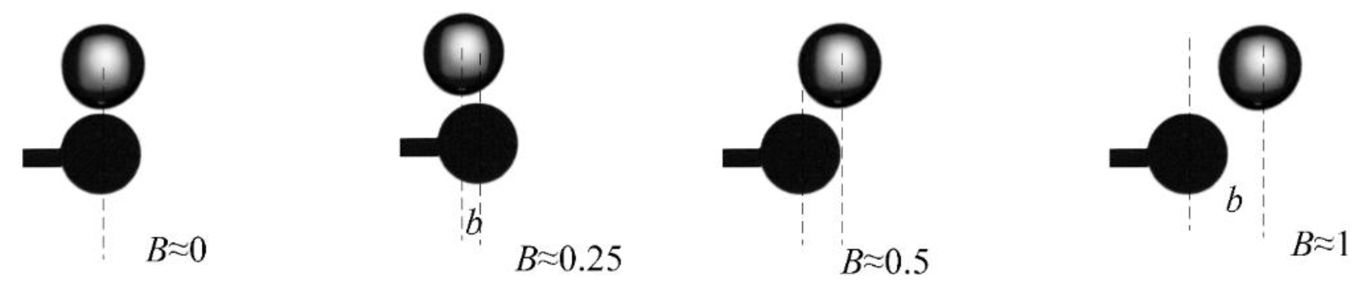
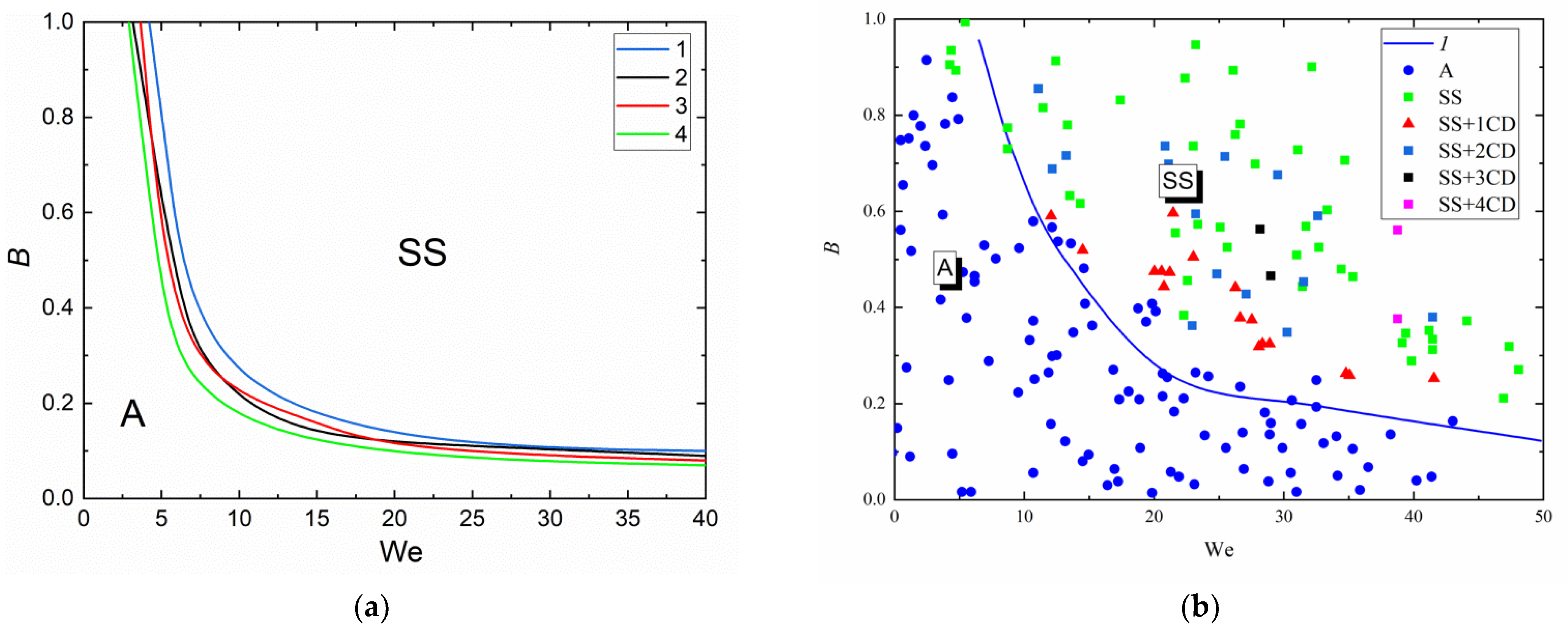
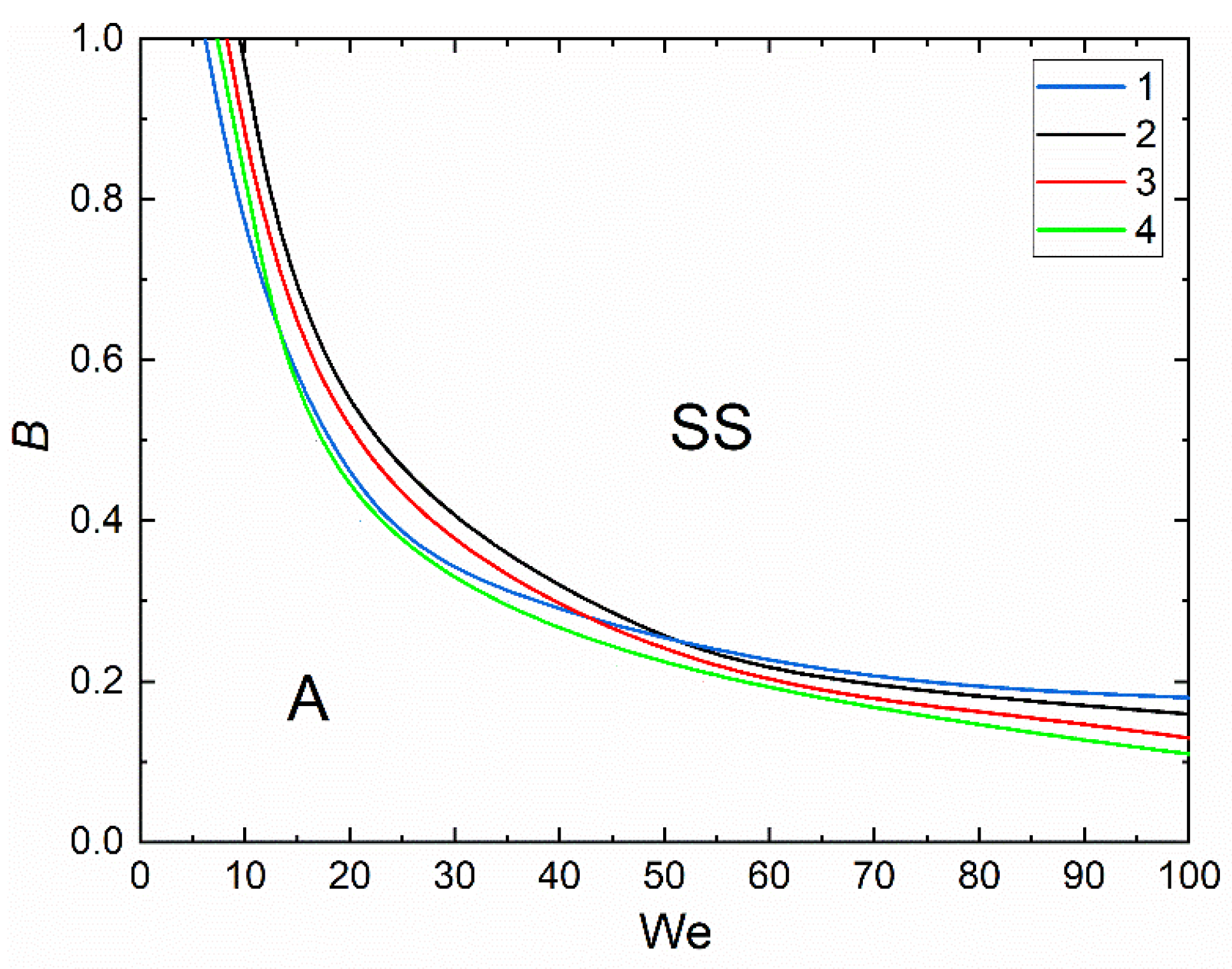
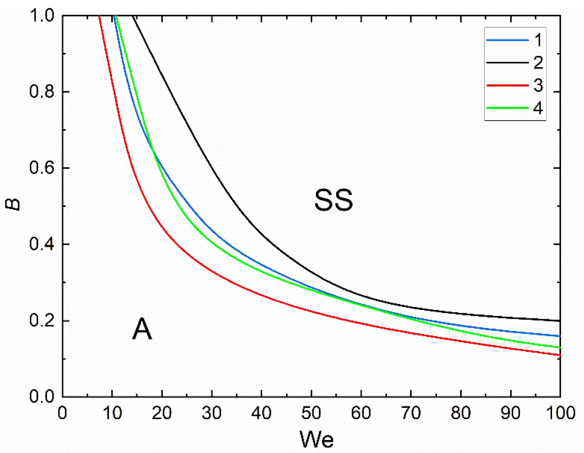
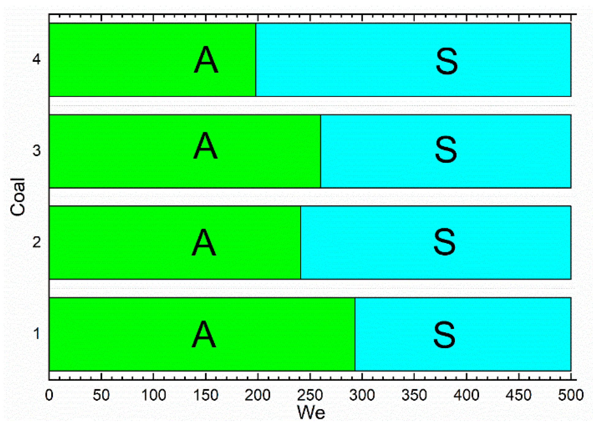
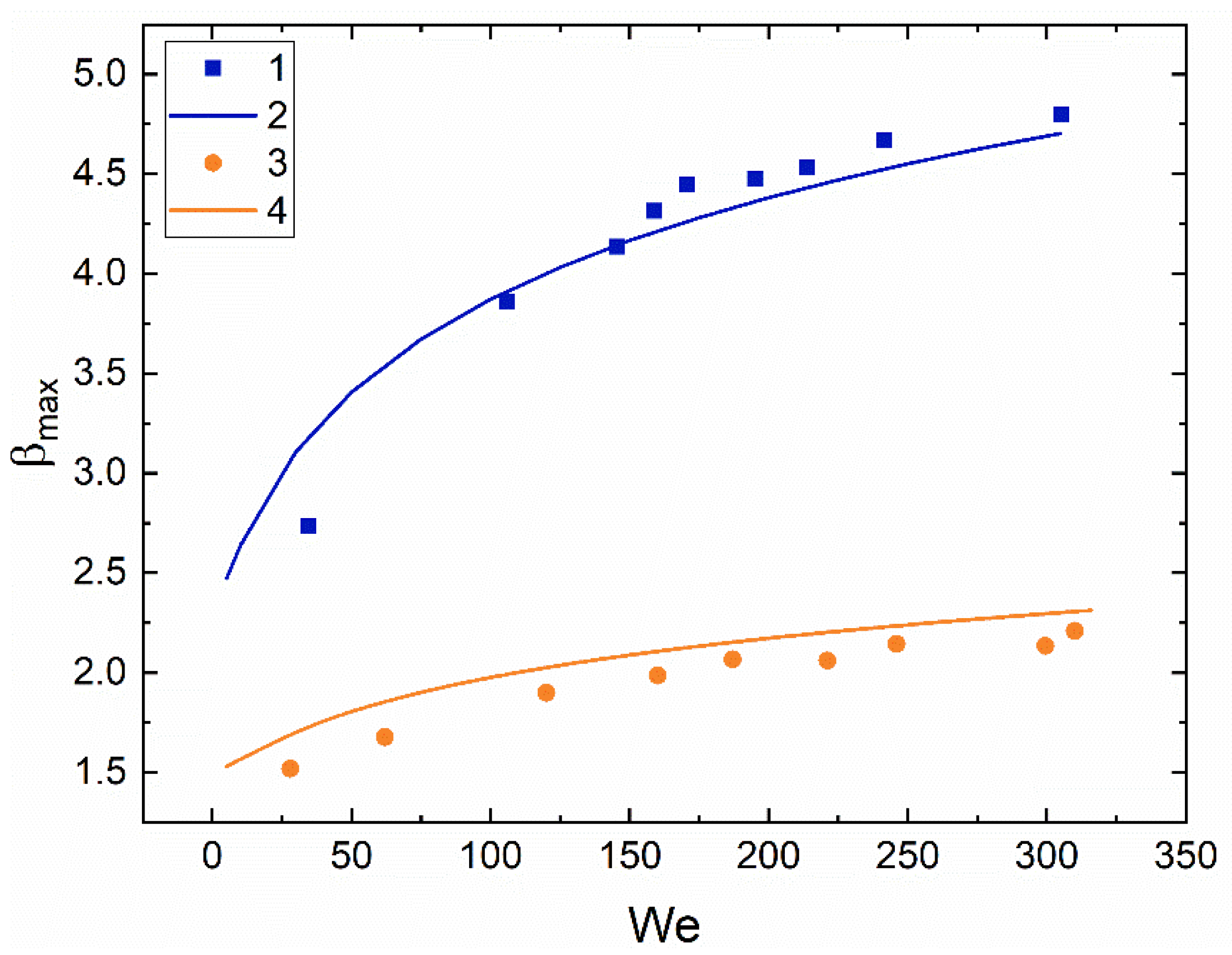
3.2. Collision Regime Maps for Liquid Droplets and Solid Particles

Known limitations of using coal–water slurries with and without petrochemicals [17,26,47] can be minimized by using an approach implying separate injection of components into combustion chambers [50]. In this case, it is necessary to determine the threshold conditions of the coalescence of liquid droplets with each other and the agglomeration of droplets with the solid particles of composite fuels. The interaction regime maps for the droplets of promising oil–water slurry components colliding with carbonaceous particles, obtained when processing the experimental results at varying droplet-to-particle size ratios, are presented in Figure 9, Figure 10, Figure 11 and Figure 12. Figure 9 and Figure 10 show the collision maps for water and used motor oil droplets (Rd = 1.1–1.2 mm) impinging on similarly-shaped coal particles of different ranks and sizes (Rp = 1.1–1.2 mm). The analysis of the maps indicates that coal rank has a rather weak effect on the interaction regime. This conclusion is crucial for fuel technologies, as it justifies the use of a wide range of coal ranks. A specific aspect of the collision of a liquid droplet with a fragment of coking coal filter cake was the sticking of coal dust on the droplet’s surface. For distilled water and used motor oil in the region of B > 0.5, agglomeration with the particles of coking coal filter cakes was only recorded at low Weber numbers (We < 4). This effect is conditioned by coal dust present on the surface of filter cake particles. It remains there after the flotation of coal during its preparation. Figure 9, Figure 10, Figure 11 and Figure 12 show the maps demonstrating the differences in the characteristics of collisions between a distilled water droplet and particles of different coal ranks (Figure 9), a used motor oil droplet and particles of different coal ranks (Figure 10), a distilled water droplet and dry particles, as well as particles wetted with used motor oil droplets (Figure 11), a used motor oil droplet and dry particles, as well as particles wetted with distilled water droplets (Figure 12). Based on the conducted experiments, reported in Section 3.1, the collision characteristics were obtained (pre-collision droplet diameter (Rd), impact velocities (Ud), and impact angle (b)) at which agglomeration and separation occurred. These results were used to calculate the Weber number (We = 2·ρ·Rd·Ud2/σ) and linear impact parameter (B = b/(Rd1 + Rp)) for each occurring regime. The obtained points were plotted on the B(We) regime map (Figure 9b).
After the points were plotted on the regime map, the boundary between agglomeration and stretching separation was identified. Then a boundary connecting these points was drawn, if 95% of the points were within the limits of a certain regime area. The true boundary is a curve with a multitude of bends, so an approximation curve was drawn.
At Δ = 1 and Rd = Rp = 1.1–1.2 mm, stretching separation dominated agglomeration (Figure 11) at We = 8–40 for all the cases of a water droplet colliding with a coal particle. Agglomeration was only recorded at B <0.2 for all the coal ranks. Additional experiments with an increase in the Weber number to 60–80 established that only stretching separation occurs consistently. This result is accounted for by a significant dominance of inertia over surface tension. The threshold values determined for the input parameters indicate that consistent agglomeration of a water droplet with a coal particle requires a low relative velocity. When droplets and particles move simultaneously, a low relative (resultant) velocity can be achieved by changing the impact angle. Figure 11 compares the experimental data with the results obtained by Pawar et al. [35] in the experimental study of the collisions between a water droplet with a radius Rd of 1.45 mm and a spherical glass particle with a contact angle of 70–80°. The differences in the transition boundaries between interaction regimes are explained by different shapes: solid coal fragments in the present experiments versus the regular spherical shape of solids in the experiments by Pawar et al. [35]. Despite the differences in the solid objects’ (particles’) shapes, the boundaries obtained from the analysis of the present experimental findings and the study by Pawar et al. [35] look identical on the regime maps and differ only in the transient (critical) values of B and We. This suggests that the experimental procedure and scheme developed in this study can be used in a wide range of applications with particles of different materials. The location and form of the transition boundaries between agglomeration and stretching separation in Figure 9 and Figure 10 are similar because of a minor change in the contact angle of coal. The contact angle is a crucial factor, as the other parameters (droplet and particle sizes, droplet velocity, density, viscosity and surface tension of water (Figure 9) and oil (Figure 10)) remained constant.
The most important property of used motor oil is its high viscosity compared to distilled water. It promotes fewer fluctuations in the shape (surface transformation) of the droplet moving in gas. High liquid viscosity also contributes to the formation of a smaller number of child droplets [51], which somewhat slows down the secondary atomization of droplets. Yet when a composite fuel is produced by the separate injection of its components, the high viscosity of used motor oil leads to an increase in the agglomeration region on the regime map. Figure 12 presents the interaction regime map for used motor oil droplets colliding with carbonaceous particles of coals of different ranks at Δ = 1. The area of agglomeration increased significantly relative to the experiments with distilled water on the axes of the Weber number and dimensionless linear impact parameter. Due to an increase in the viscous friction forces at low (under 10) We numbers the droplet did not separate into several fragments even at B > 0.5. The droplet stuck to the coal particle. The particle shape also had some effect on the collision regime. For instance, when a liquid droplet collided with a cube- or polyhedron-shaped particle, agglomeration was recorded until B = 1. At the same time, when particles had sharp edges, the liquid trickled down the surface, and stretching separation was recorded.
When the approximation curves for the boundaries of agglomeration–stretching separation during the interaction of water (Figure 9) and used motor oil droplets (Figure 10) with coal particles were plotted, equations were obtained such as the following:
B = nWek,
The empirical constants n and k are summed up in Table 3. In Equation (1), the coefficient k depends on the type of liquid and is constant for water (k = −1.1) and used oil (k = −0.79). The coefficient k is lower for oil than for water due to the physical properties of used oil (higher viscosity and lower surface tension). The approximation coefficient n in the Equation (1) makes it possible to factor in the effect of changing coal properties (moisture and ash content). The relationship between the free term n and the ratio of the fuel moisture content (Wa) to ash content (Ad) takes the form:
n = 2.789(Wa/Ad)/((Wa/Ad)0.518 – 0.2485) in the interaction of a water droplet with a coal particle;
n = 5.453(Wa/Ad)/((Wa/Ad)1.345 + 0.0908) in the interaction of an oil droplet with a coal particle.
The moisture content (Wa) and ash content (Ad) were used in the analysis of the findings, as these parameters have a significant effect on the collision of a droplet with a solid particle or substrate in a real furnace. The moisture content affects the filling of the solid material pores. The higher the moisture content, the fewer irregularities and pores there are on the solid material surface. That increases the energy used to overcome friction when liquid spreads over the surface. With highly porous solid materials, the liquid will move on the peaks of irregularities, whereas the pores filled with air will practically not retard its movement. The ash content of a material shows what proportion of it will remain after pyrolysis and combustion in a high-temperature environment. This parameter is important for industrial plants when calculating the amount of energy released from the fuel combustion or combustible gases emitted in its pyrolysis. Thus, the higher the ash content, the more the material surface after combustion/pyrolysis will resemble the original one. It will thus be possible to predict the parameters of the collision of a droplet with a solid particle or substrate with greater accuracy.
The agglomeration and stretching separation boundaries on the B(We) maps during the collisions of water and oil droplets with dry and wetted particles (Figure 11 and Figure 12) are described by the power function (1). The empirical constants are summed up in Table 3. The general form of approximations indicates that despite the significantly varying properties of water and oil, the conditions of the interaction of liquid droplets with solid particles are quite similar. It is an important finding for practical applications. The calculated approximation coefficients make it possible to predict threshold shifts in transition boundaries between the collision regimes for different fuel mixture components.

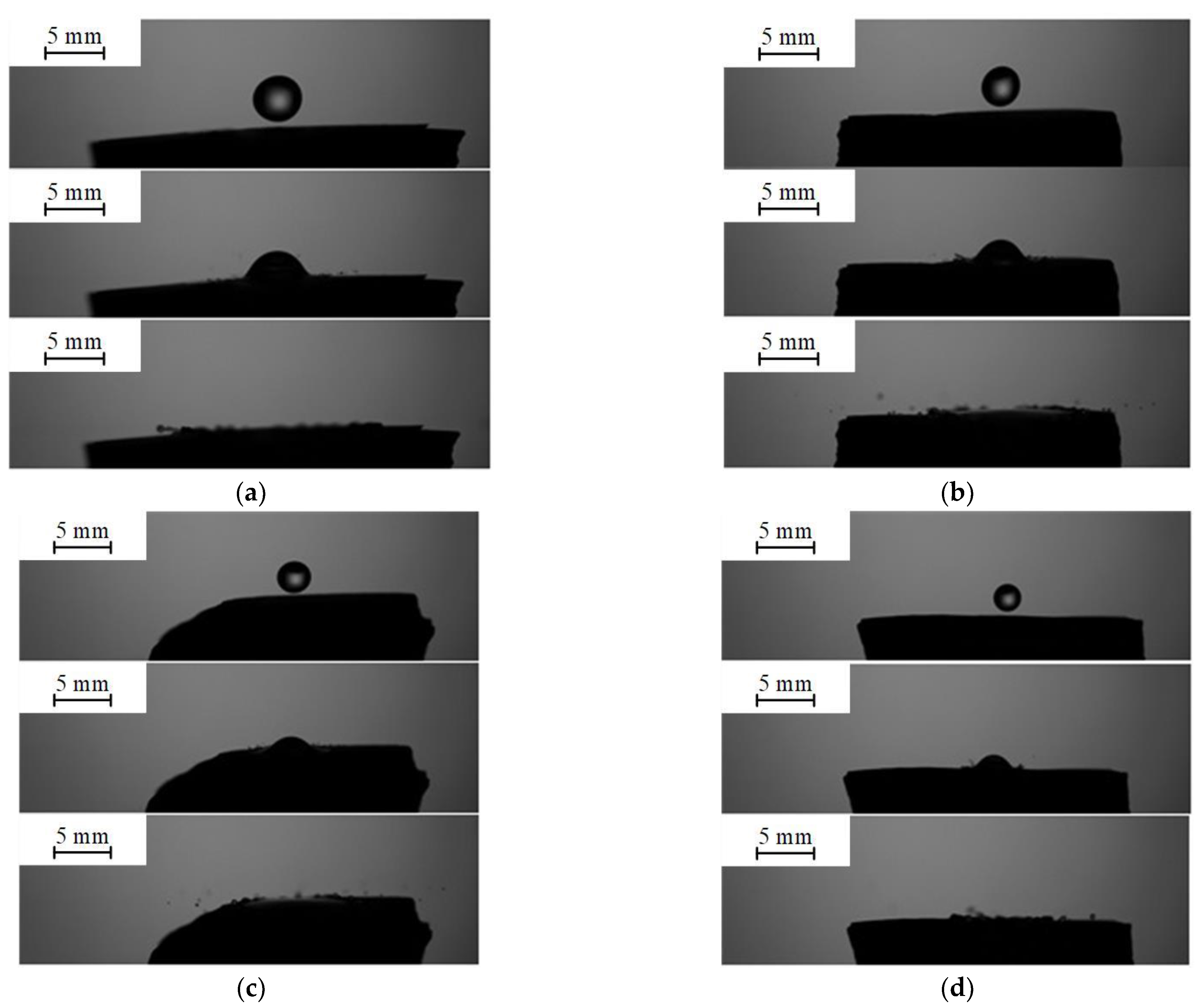
3.3. Collisions of Liquid Droplets with Solid Substrates

For a more extensive study of the effect of the near-surface properties of the material, additional experiments were conducted with monolithic coal fragments and pressed pellets from ground coal. Such conditions correspond to applications in which coal is wetted before its thermal treatment in pyrolysis, gasification and combustion technologies. The images in Figure 13, Figure 14 and Figure 15 indicate that the main factors responsible for the occurrence of one of the interaction regimes are the resultant velocity and size of droplets. Both of these parameters are factored into the Weber number. Apart from that, the properties of the hard surface also had a significant effect on the occurrence of regimes. A lower velocity was required for separation when a liquid droplet collided with a monolithic coal fragment than when it collided with a pressed pellet.
Figure 13 shows the images of collisions of distilled water droplets with carbonaceous substrates in the form of monolithic anthracite fragments when varying the droplet sizes in the range of Rd = 1.1–2 mm. It is clear from Figure 13a–с that droplet size has a minor effect on the separation of droplets and formation of secondary fragments at a constant velocity Ud of 2.6 m/s. When a distilled water droplet with a radius Rd of 1.1–2 mm collides with a carbonaceous substrate, separation occurs consistently. It is noteworthy that the impact angle has a significant effect on the collision regime. It is varied by changing not only the direction of spraying through the nozzle but also the inclination angle of the solid surface. In this study, this factor was not varied. An identical scheme of the droplet–substrate interaction was considered.
Figure 14 shows the images of collisions of distilled water droplets with carbonaceous substrates in the form of monolithic anthracite fragments when varying the droplet impact velocity. Agglomeration was the regime in which the interaction with a solid surface did not produce secondary fragments. On impact, the liquid enveloped the particle (Figure 5e,f). In the case of a substrate, the agglomeration regime was when the droplet spread over it (Figure 14a). Child droplet formation was considered to be the separation regime (Figure 14b,c). It is clear from Figure 14b,c that at droplet impact velocities of 2.6 m/s, their collisions with a carbonaceous substrate lead to separation. However, at impact velocities of 0.9 m/s, agglomeration occurs (Figure 14a).
Figure 15 presents the images of collisions of distilled water droplets with carbonaceous substrates at a constant radius of droplets Rd of 2 mm and velocity Ud of 2.6 m/s when varying substrate types. Separation was recorded in the collision of a droplet with a substrate irrespective of its type. Based on the data obtained, collision regime maps were plotted for agglomeration and separation during the collision of a droplet with pressed (Figure 16) and monolithic (Figure 17) coal substrates. It can be concluded that with an increase in the contact angle, separation requires lower Weber numbers. The critical Weber number variation for different types of coals corresponds to 227–260. The experimental results with the filter cake of coking bituminous coal were significantly different from the general trend in the other tests in terms of the threshold conditions of transition to separation. In particular, this regime required the critical Weber number in the range of 292–300. Such a specific aspect is conditioned by a greater porosity of pellets from filter cake and the presence of fine coal dust particles facilitating the cohesion of liquid with the solid surface. Some particles ground to a size of 60 µm were additionally atomized under the press. This provided a more uniform surface than that of pellets from different coal ranks. The absence of voids, cavities and protruding particles contributed to a more even spreading of liquid droplets over the surface without their secondary atomization. Moreover, better wettability of pressed pellets compared to other surfaces may have an additional effect on the threshold conditions of the transition from agglomeration to separation. The presence of surface-active flotation agents on the particle surface reduces the contact angle for the pellets from filter cake to a minimum (Table 2).
It is possible to control the constant size and density of pellets from ground coal. Actual fuel technologies employ coal particles atomized to certain sizes. Despite the possibility of controlling the surface quality with a high degree of precision, it is interesting to vary the critical Weber numbers in the experiments with monolithic coal fragments. To that end, the monolithic samples were cut and polished on two sides to achieve smoothness and maintain the sample inclination angle on the substrate. Figure 17 presents a collision regime map factoring in the effect of a substrate type and angle on the outcomes of the droplet–surface interaction. It is clear that in the collision of a droplet with a monolithic coal fragment surface, droplet atomization and separation require lower Weber numbers. A decrease in the critical We for the monolithic fragment of coking coal filter cake compared to the pressed pellet was approx. 18%. For anthracite, Wecr decreased by 22–24%. One of the reasons for a lower critical Weber number is local defects of the coal surface (the presence of pores and projections). The samples exposed to water droplets later lost their strength, cracked and were destroyed even under minimal impact. However, the main reason for a reduction in Wecr is the surface quality. Table 2 shows that the contact angles of the monolithic fragments are much greater than those of the pressed pellets. Droplets encountered greater resistance during spreading, though a smaller area of contact of the liquid with the surface led to stress concentration in the liquid. If the surface tension forces were overcome, the droplet spread immediately. In that case, inertia dominated viscosity and surface tension, thus leading to droplet separation.
An important parameter to be taken into account when studying the collisions of a droplet with a solid surface is the maximum spread diameter. It is characterized by the maximum spread factor (βmax), which is determined as a ratio of the maximum diameter of the droplet (Dmax) to its pre-collision diameter (Dd). Two approaches—empirical and theoretical (based on the energy equation)—are most frequently applied to finding the Dmax/Dd ratio. The empirical approach implies that with high viscous forces in the spreading droplet, the maximum spread factor is determined from the interaction of inertia with viscosity. βmax is taken to follow the power law: βmax~nWek [52,53,54,55] and βmax~nWekRem [56,57,58,59].
One of the widely used methods to predict the spreading of a droplet over a surface is the method relying on the energy equation. When a liquid droplet collides with a solid surface, the energy equation can be written as [60]
E k 1 + E S 1 = E S 2 + E d
where E k 1 = 1 2 ρ U d 2 π 6 D d 3 is the kinetic energy of the droplet before the collision (J); E S 1 = σ π D d 2 is the surface energy of the droplet before the collision (J); E S 2 = π 4 D max 2 σ ( 1 cos θ a ) is the surface energy after the collision (J); E d = π 3 ρ U d 2 D d D max 2 Re 0.5 is the energy lost to viscous dissipation (J).
Using Equation (2) and the energy components, Pasandideh-Fard et al. [60] obtained an equation to determine the maximum spread factor:
β max = D max D d = We + 12 3 ( 1 cos θ a ) + 4 We / Re
Figure 18 presents the typical curves for the interaction of distilled water and used motor oil droplets on a pressed pellet from anthracite versus the We number. The curves are described by an exponential function. At higher We numbers, the values of βmax for water and oil differ almost twofold, although the surface tension of oil is 2.2 times as low as that of water. This can be explained by the fact that in the interaction of a used motor oil droplet with a pelletized coal sample, the viscous friction forces dominate inertia due to the high viscosity of the liquid (it is more than tenfold as high as that of water). Figure 18 also presents the values of βmax calculated from Equation (3). In the calculations, the dynamic contact angle θa was assumed to be constant at different We numbers and equaled 75° for water and 126° for oil. The maximum discrepancy between the experimental and theoretical values was found to be no more than 15% at low We. This is accounted for by the fact that at low velocities of droplets before their interaction with a solid surface, the spreading is significantly affected by the characteristics of the surface of the material (wettability, roughness and chemical inhomogeneity). Equation (3) does not take into account the characteristics of the surface with which a droplet collides. At higher velocities, the influence of inertia is greater than that of the surface forces, and the effect of surface roughness and wettability is lessened. With an increase in the Weber number, the discrepancy between the theoretical and empirical values becomes smaller.
Table S1 (Supplementary Materials) presents the known critical values of dimensionless numbers describing the regime boundaries for the interaction of droplets with substrates [61,62,63,64,65,66,67,68] and particles [35,69,70,71,72,73,74]. In the study of droplet collisions, the liquid under consideration was water; the materials of particles and surfaces were metal, glass and polymers (e.g., aluminum [63,64,67] and glass [35,63,66,73]). The collision regime maps were plotted in the Oh(Re), We, Re(T*) and T(We) coordinates for the interaction of droplets with substrates and in the B(We), Δ(We), Oh(Re) and We(T) coordinates for the interaction with particles. In this study, when droplets collided with coal surfaces and separation occurred, OhRe1.25 was no less than 134 (in the collision of a distilled water droplet with a monolithic anthracite fragment), which is consistent with the data [61]. The comparison of the characteristics of the interaction of different liquid droplets with a Perspex substrate reveals that splashing (separation) occurred at We > 156 (100% jet fuel) and We > 156 (water) [62], whereas in the collision of a water droplet with different coal substrates separation occurred at We = 198–293 (Figure 16 and Figure 17). As noted by Yan et al. [74], not only the liquid properties and impact velocity (droplet kinematics), but also the physical properties of the surface have a significant effect on the collision outcome. These include its wettability, roughness and temperature. It has been established [63] that with an increase in roughness (estimated from the average roughness of the surface) Wecr decreases according to the logarithmic law. An analysis of Table S1 indicates that in the interaction of liquid (water, isopropanol) droplets with particles, the boundary between agglomeration (deposition) and separation corresponds to We ≈ 50 [35,70,71,72]. A rise in the particle surface temperature above the liquid boiling temperature increases the critical Weber number [69]. In this study, separation (splash/ breakup/disintegration) in the collisions of distilled water droplets with coal particles occurred at lower Weber numbers (We > 15 and B > 0.2). This phenomenon can be attributed to the fact that the studies considered in Table S1 dealt with polished spherical particles. In this study, coal particles had an irregular geometric shape, and their surface texture was characterized by inhomogeneous roughness, which led to earlier separation. With used motor oil, separation occurs at higher Weber numbers than it does with water (We > 50 and B > 0.2), which is consistent with the previous studies. In particular, Rein et al. [75] established that an increase in the liquid viscosity should delay splashing. Thus, the findings obtained in the conducted research are fundamental for the development of technologies of contact interaction of droplets with particles involved in a wide range of applications.

4. Conclusions

(i) Following the conducted experiments, collision regime maps for droplets and solid particles were constructed in the system of coordinates taking the dimensionless impact parameter and the critical Weber number into account. Stretching separation and agglomeration regimes were distinguished. Differences were identified in the way the droplets of a combustible and noncombustible component interact with particles of coal of different ranks (brown and coking coal, filter cake of coking coal and anthracite).
(ii) The comparison of the droplet–particle and droplet–droplet collision regimes revealed conditions when the regimes on the maps are identical and significantly different. In particular, agglomeration that is analogous to coalescence in the case of droplet–droplet collisions occurs within the whole range of B and at We < 8. When droplets interact with each other at these Weber numbers, bounce is most frequent. Increasing the Weber number to 40 resulted in agglomeration at B < 0.2, whereas in the collision of droplets with each other, there was separation. These specific aspects are to be considered when the jets of different components are mixed in combustion chambers for the formation of composite liquid fuel droplets or their secondary atomization.
(iii) The research findings are of interest within the field of developing the technologies of secondary atomization of liquid droplets and agglomeration of particles and droplets. Specifically, these technologies make it possible to solve the common problems of composite fuel sticking on the flow channel walls of nozzles and the separation of CWSP components after primary atomization with spray systems. The constructed interaction regime maps for dry and wetted particles colliding with liquid droplets help predict the conditions for the consistent formation of two- and three-component fuel droplets.

Supplementary Materials

The following supporting information can be downloaded at: www.mdpi.com/article/10.3390/en15218288/s1, Table S1: Critical values of dimensionless numbers describing the regime boundaries; Video S1: Images of droplet–particle collision in the agglomeration regime; Video S2: Images of droplet–particle collision in the stretching separation regime.

Author Contributions

Conceptualization, P.S. and P.T.; methodology, K.P. and P.T.; investigation, A.I., K.P. and P.T.; writing—original draft preparation, A.I., P.T. and P.S.; writing—review and editing, A.I. and P.S. All authors have read and agreed to the published version of the manuscript.

Funding

The Research was supported by the Russian Science Foundation (project 18-71-10002-π, https://rscf.ru/en/project/21-71-03001/, accessed on 30 July 2021).

Conflicts of Interest

The authors declare no conflict of interest.

Nomenclature

Adash content, %
blinear approach parameter, m
Bdimensionless linear interaction parameter
Dddroplet diameter, m
Dmaxmaximum spread diameter of the droplet, m
Ek1kinetic energy of the droplet before the collision, J
ES1, ES2surface energy of the droplet before and after the collision, J
Edenergy lost to viscous dissipation, J
Ntinumber of child droplets;
rdradius of child droplets, m;
Rd, Rpdroplet and particle radii, m;
S0droplet surface area before interaction, m2;
S1surface area of post-collision secondary droplets, m2;
Udvelocity, m/s
T*dimensionless temperature;
Ttemperature, °C;
V0total volume of the droplet before interaction, m3
V1total volume of droplets after interaction, m3
ReReynolds number
WeWeber number
Wecrcritical Weber number
Wamoisture content, %
OhOhnesorge number
n, k, mempirical coefficients
Greek symbols
αdimpact angle
βmaxmaximum spread factor
θadynamic contact angle
ΔParticle–droplet size ratio
µdynamic viscosity, Pa∙s
ρliquid density, kg/m3
σsurface tension of liquid, N/m
Abbreviations
Aagglomeration
Sseparation
SSstretching separation

References

  1. Wang, G.; Deng, J.; Zhang, Y.; Zhang, Q.; Duan, L.; Hao, J.; Jiang, J. Air Pollutant Emissions from Coal-Fired Power Plants in China over the Past Two Decades. Sci. Total Environ. 2020, 741, 140326. [Google Scholar] [CrossRef] [PubMed]
  2. Nyashina, G.; Legros, J.C.; Strizhak, P. Environmental Potential of Using Coal-Processing Waste as the Primary and Secondary Fuel for Energy Providers. Energies 2017, 10, 405. [Google Scholar] [CrossRef] [Green Version]
  3. Munawer, M.E. Human Health and Environmental Impacts of Coal Combustion and Post-Combustion Wastes. J. Sustain. Min. 2018, 17, 87–96. [Google Scholar] [CrossRef]
  4. Dudley, B. BP Statistical Review of World Energy. BP Stat. Rev. 2018, 6, 00116. [Google Scholar]
  5. Ahmad, T.; Zhang, D. A Critical Review of Comparative Global Historical Energy Consumption and Future Demand: The Story Told so Far. Energy Rep. 2020, 6, 1973–1991. [Google Scholar] [CrossRef]
  6. Miller, B.G. Clean Coal Engineering Technology; Elsevier: Amsterdam, The Netherlands, 2010. [Google Scholar]
  7. Cansino, J.M.; Román-Collado, R.; Merchán, J. Do Spanish Energy Efficiency Actions Trigger JEVON’S Paradox? Energy 2019, 181, 760–770. [Google Scholar] [CrossRef]
  8. Zaitsev, A.S.; Taburchinov, R.I.; Ozerova, I.P.; Pereira, A.O.; Egorov, R.I. Allothermal Gasification of Peat and Lignite by a Focused Light Flow. Appl. Sci. 2020, 10, 2640. [Google Scholar] [CrossRef]
  9. Feng, Z.; Bai, Z.; Hou, R.; Guo, Z.; Kong, L.; Bai, J.; Li, W. Co-Pyrolysis of Mild Liquefaction Solid Product and Low Rank Coals: Products Distributions, Products Properties and Interactions. Fuel 2021, 306, 121719. [Google Scholar] [CrossRef]
  10. Spiegl, N.; Long, X.; Berrueco, C.; Paterson, N.; Millan, M. Oxy-Fuel Co-Gasification of Coal and Biomass for Negative CO2 Emissions. Fuel 2021, 306, 121671. [Google Scholar] [CrossRef]
  11. Bielecki, Z.; Ochowiak, M.; Włodarczak, S.; Krupińska, A.; Matuszak, M.; Jagiełło, K.; Dziuba, J.; Szajna, E.; Choiński, D.; Odziomek, M.; et al. The Optimal Diameter of the Droplets of a High-Viscosity Liquid Containing Solid State Catalyst Particles. Energies 2022, 15, 3937. [Google Scholar] [CrossRef]
  12. Jiang, P.; Xie, C.; Luo, C.; Meng, W.; Yang, G.; Yu, G.; Gong, Y.; Xu, M.; Wu, T. Distribution and Modes of Occurrence of Heavy Metals in Opposed Multi-Burner Coal-Water-Slurry Gasification Plants. Fuel 2021, 303, 121163. [Google Scholar] [CrossRef]
  13. Chu, R.; Li, Y.; Meng, X.; Fan, L.; Wu, G.; Li, X.; Jiang, X.; Yu, S.; Hu, Y. Research on the Slurrying Performance of Coal and Alkali-Modified Sludge. Fuel 2021, 294, 120548. [Google Scholar] [CrossRef]
  14. Adnan, M.A.; Hidayat, A.; Hossain, M.M.; Muraza, O. Transformation of Low-Rank Coal to Clean Syngas and Power via Thermochemical Route. Energy 2021, 236, 121505. [Google Scholar] [CrossRef]
  15. Adnan, M.A.; Xiong, Q.; Hidayat, A.; Hossain, M.M. Gasification Performance of Spirulina Microalgae–A Thermodynamic Study with Tar Formation. Fuel 2019, 241, 372–381. [Google Scholar] [CrossRef]
  16. Zeng, S.; Zhou, H.; Qian, Y. Review and Techno-Economic Analysis of Coal Pyrolysis to Liquid and Oil Shale to Liquid Processes. CIESC J. 2017, 68, 3658–3668. [Google Scholar] [CrossRef]
  17. Shadrin, E.Y.; Anufriev, I.S.; Butakov, E.B.; Kopyev, E.P.; Alekseenko, S.V.; Maltsev, L.I.; Sharypov, O. V Coal-Water Slurry Atomization in a New Pneumatic Nozzle and Combustion in a Low-Power Industrial Burner. Fuel 2021, 303, 121182. [Google Scholar] [CrossRef]
  18. Zhu, M.; Zhang, Z.; Zhang, Y.; Liu, P.; Zhang, D. An Experimental Investigation into the Ignition and Combustion Characteristics of Single Droplets of Biochar Water Slurry Fuels in Air. Appl. Energy 2017, 185, 2160–2167. [Google Scholar] [CrossRef]
  19. Yan, M.; Shi, Y. Thermal and Economic Analysis of Multi-Effect Concentration System by Utilizing Waste Heat of Flue Gas for Magnesium Desulfurization Wastewater. Energies 2020, 13, 5384. [Google Scholar] [CrossRef]
  20. Staroń, A.; Kowalski, Z.; Staroń, P.; Banach, M. Studies on CWL with Glycerol for Combustion Process. Environ. Sci. Pollut. Res. 2019, 26, 2835–2844. [Google Scholar] [CrossRef] [Green Version]
  21. Niu, J.; Liu, S.; Xu, J. Investigation into Atomization Spray Blending Property in Heavy Crude Oil Extraction under Laboratory Conditions. J. Pet. Sci. Eng. 2020, 184, 106494. [Google Scholar] [CrossRef]
  22. Yuan, N.; Zhao, A.; Hu, Z.; Tan, K.; Zhang, J. Preparation and Application of Porous Materials from Coal Gasification Slag for Wastewater Treatment: A Review. Chemosphere 2022, 287, 132227. [Google Scholar] [CrossRef] [PubMed]
  23. Wang, W.; Luo, X.; Li, Q.; Xu, K.; Liu, J. Operation Optimization and Costs Analysis of the Wet Desulfurization System in an Ultra-Supercritical Coal-Fired Power Plants. Environ. Prog. Sustain. Energy 2021, 40, e13527. [Google Scholar] [CrossRef]
  24. Zheng, J.; Xu, Y.; Wang, Q.; He, H. Characteristics of Particle Size and Velocity of Droplets of Coal Water Slurry Subjected to Air-Blast Electrostatic Atomization Using a Phase Doppler Particle Analyzer. J. Electrostat. 2019, 98, 40–48. [Google Scholar] [CrossRef]
  25. Wu, X.; Gong, Y.; Guo, Q.; Xue, Z.; Yu, G. Experimental Study on the Atomization and Particle Evolution Characteristics in an Impinging Entrained-Flow Gasifier. Chem. Eng. Sci. 2019, 207, 542–555. [Google Scholar] [CrossRef]
  26. Wu, X.; Guo, Q.; Gong, Y.; Liu, J.; Luo, X.; Wu, T.; Yu, G. Influence of Burner Geometry on Atomization of Coal Water Slurry in an Entrained-Flow Gasifier. Chem. Eng. Sci. 2022, 247, 117088. [Google Scholar] [CrossRef]
  27. Zhao, H.; Liu, H.-F.; Xu, J.-L.; Li, W.-F.; Cheng, W. Breakup and Atomization of a Round Coal Water Slurry Jet by an Annular Air Jet. Chem. Eng. Sci. 2012, 78, 63–74. [Google Scholar] [CrossRef]
  28. Khojasteh, D.; Kazerooni, N.M.; Marengo, M. A Review of Liquid Droplet Impacting onto Solid Spherical Particles: A Physical Pathway to Encapsulation Mechanisms. J. Ind. Eng. Chem. 2019, 71, 50–64. [Google Scholar] [CrossRef]
  29. Gvozdyakov, D.; Zenkov, A. Improvement of Atomization Characteristics of Coal-Water Slurries. Energy 2021, 230, 120900. [Google Scholar] [CrossRef]
  30. Zhu, M.; Zhang, Z.; Zhang, Y.; Setyawan, H.; Liu, P.; Zhang, D. An Experimental Study of the Ignition and Combustion Characteristics of Single Droplets of Biochar-Glycerol-Water Slurry Fuels. Proc. Combust. Inst. 2017, 36, 2475–2482. [Google Scholar] [CrossRef]
  31. Meng, Z.; Yang, Z.; Yin, Z.; Li, Y.; Song, X.; Zhao, J.; Wu, W. Effects of Coal Slime on the Slurry Ability of a Semi-Coke Water Slurry. Powder Technol. 2020, 359, 261–267. [Google Scholar] [CrossRef]
  32. Solomatin, Y.; Shlegel, N.E.E.; Strizhak, P.A.A. Atomization of Promising Multicomponent Fuel Droplets by Their Collisions. Fuel 2019, 255, 115751. [Google Scholar] [CrossRef]
  33. Wang, S.; Liu, J.; Pisupati, S.V.; Li, D.; Wang, Z.; Cheng, J. Dispersion Mechanism of Coal Water Slurry Prepared by Mixing Various High-Concentration Organic Waste Liquids. Fuel 2021, 287, 119340. [Google Scholar] [CrossRef]
  34. Dremicheva, E.S.; Laptev, A.G. Viscous Properties of Petroleum-Containing Waste Waters from Industrial Enterprises. J. Eng. Phys. Thermophys. 2021, 94, 1326–1330. [Google Scholar] [CrossRef]
  35. Pawar, S.K.; Henrikson, F.; Finotello, G.; Padding, J.T.; Deen, N.G.; Jongsma, A.; Innings, F.; Kuipers, J.A.M.H. An Experimental Study of Droplet-Particle Collisions. Powder Technol. 2016, 300, 157–163. [Google Scholar] [CrossRef] [Green Version]
  36. Kim, J.; Lee, S.; Tahmasebi, A.; Jeon, C.-H.; Yu, J. A Review of the Numerical Modeling of Pulverized Coal Combustion for High-Efficiency, Low-Emissions (HELE) Power Generation. Energy Fuels 2021, 35, 7434–7466. [Google Scholar] [CrossRef]
  37. Kuznetsov, G.V.; Syrodoy, S.V.; Gutareva, N.Y.; Nigay, N.A. Mathematical Modeling of the Thermochemical Processes of Nitrogen Oxides Sequestration during Combustion of Wood-Coal Mixture Particles. J. Energy Inst. 2021, 96, 280–293. [Google Scholar] [CrossRef]
  38. Egorov, R.I.; Taburchinov, R.I. The Numerical Study of Allothermal Gasification of the Peat by the Focused Light Flow. Appl. Therm. Eng. 2021, 195, 117253. [Google Scholar] [CrossRef]
  39. Kajitani, S.; Tay, H.-L.; Zhang, S.; Li, C.-Z. Mechanisms and Kinetic Modelling of Steam Gasification of Brown Coal in the Presence of Volatile–Char Interactions. Fuel 2013, 103, 7–13. [Google Scholar] [CrossRef]
  40. Vershinina, K.Y.; Dorokhov, V.V.; Nyashina, G.S.; Romanov, D.S. Environmental Aspects and Energy Characteristics of the Combustion of Composite Fuels Based on Peat, Oil, and Water. Solid Fuel Chem. 2019, 53, 294–302. [Google Scholar] [CrossRef]
  41. Gaber, C.; Wachter, P.; Demuth, M.; Hochenauer, C. Experimental Investigation and Demonstration of Pilot-Scale Combustion of Oil-Water Emulsions and Coal-Water Slurry with Pronounced Water Contents at Elevated Temperatures with the Use of Pure Oxygen. Fuel 2020, 282, 118692. [Google Scholar] [CrossRef]
  42. Yi, S.; Hao, L.; Li, S.; Song, W. The Influence of Water Content in Rice Husk Bio-Oil on the Rheological Properties of Coal Bio-Oil Slurries. Energy 2019, 189, 116307. [Google Scholar] [CrossRef]
  43. Chen, X.; Wang, C.; Wang, Z.; Zhao, H.; Liu, H. Preparation of High Concentration Coal Water Slurry of Lignite Based on Surface Modification Using the Second Fluid and the Second Particle. Fuel 2019, 242, 788–793. [Google Scholar] [CrossRef]
  44. Li, Y.; Zhou, F.; Wang, J.; Li, B.; Xu, H.; Yao, E.; Zhao, L. Influence of Nanoemulsion Droplet Size of Removing Water Blocking Damage in Tight Gas Reservoir. Energies 2022, 15, 5283. [Google Scholar] [CrossRef]
  45. Wang, X.; Dou, L.; Hossain, M.; Rezaee, R.; Zhao, F.; Dong, Z.; Wang, C.; Zhang, W.; Yu, R. Pore Connectivity Characteristics and Controlling Factors for Black Shales in the Wufeng-Longmaxi Formation, Southeastern Sichuan Basin, China. Energies 2022, 15, 2909. [Google Scholar] [CrossRef]
  46. Kuznetsov, G.V.; Islamova, A.G.; Orlova, E.G.; Strizhak, P.A.; Feoktistov, D.V. Physicochemical Features of the Effect of Special Water-Based Fire Retardants on Forest Materials. Fire Saf. J. 2021, 123, 103371. [Google Scholar] [CrossRef]
  47. Egorov, R.I.; Tkachenko, P.P.; Taburchinov, R.I.; Chulkov, A.O. The Propagation and Ignition of the Finely Dispersed Coal-Water Aerosol. Fuel 2020, 263, 116767. [Google Scholar] [CrossRef]
  48. Lin, Z.; Chi, S.; Ye, J.; Zhu, Z.; Li, Y.; Jin, Y. Effect of Liquid Layer on the Motion of Particle during Oblique Wet Collision. Adv. Powder Technol. 2021, 32, 3259–3267. [Google Scholar] [CrossRef]
  49. Islamova, A.G.; Kerimbekova, S.A.; Shlegel, N.E.; Strizhak, P.A. Droplet-Droplet, Droplet-Particle, and Droplet-Substrate Collision Behavior. Powder Technol. 2022, 403, 117371. [Google Scholar] [CrossRef]
  50. Tkachenko, P.P.; Shlegel, N.E.; Strizhak, P.A. Experimental Research of Liquid Droplets Colliding with Solid Particles in a Gaseous Medium. Chem. Eng. Res. Des. 2022, 177, 200–209. [Google Scholar] [CrossRef]
  51. Shlegel, N.E.; Tkachenko, P.P.; Strizhak, P.A. Influence of Viscosity, Surface and Interfacial Tensions on the Liquid Droplet Collisions. Chem. Eng. Sci. 2020, 220, 115639. [Google Scholar] [CrossRef]
  52. Biance, A.L.; Chevy, F.; Clanet, C.; Lagubeau, G.; Quéré, D. On the Elasticity of an Inertial Liquid Shock. J. Fluid Mech. 2006, 554, 47–66. [Google Scholar] [CrossRef]
  53. Lastakowski, H.; Boyer, F.; Biance, A.L.; Pirat, C.; Ybert, C. Bridging Local to Global Dynamics of Drop Impact onto Solid Substrates. J. Fluid Mech. 2014, 747, 103–118. [Google Scholar] [CrossRef]
  54. Tran, T.; Staat, H.J.J.; Prosperetti, A.; Sun, C.; Lohse, D. Drop Impact on Superheated Surfaces. Phys. Rev. Lett. 2012, 108, 036101. [Google Scholar] [CrossRef] [PubMed] [Green Version]
  55. Liang, G.; Shen, S.; Guo, Y.; Zhang, J. Boiling from Liquid Drops Impact on a Heated Wall. Int. J. Heat Mass Transf. 2016, 100, 48–57. [Google Scholar] [CrossRef]
  56. Negeed, E.S.R.; Hidaka, S.; Kohno, M.; Takata, Y. High Speed Camera Investigation of the Impingement of Single Water Droplets on Oxidized High Temperature Surfaces. Int. J. Therm. Sci. 2013, 63, 1–14. [Google Scholar] [CrossRef]
  57. Roisman, I.V. Inertia Dominated Drop Collisions. II. An Analytical Solution of the Navier–Stokes Equations for a Spreading Viscous Film. Phys. Fluids 2009, 21, 052104. [Google Scholar] [CrossRef]
  58. Negeed, E.-S.R.; Ishihara, N.; Tagashira, K.; Hidaka, S.; Kohno, M.; Takata, Y. Experimental Study on the Effect of Surface Conditions on Evaporation of Sprayed Liquid Droplet. Int. J. Therm. Sci. 2010, 49, 2250–2271. [Google Scholar] [CrossRef]
  59. Bayer, I.S.; Megaridis, C.M. Contact Angle Dynamics in Droplets Impacting on Flat Surfaces with Different Wetting Characteristics. J. Fluid Mech 2006, 558, 415–449. [Google Scholar] [CrossRef]
  60. Pasandideh-Fard, M.; Qiao, Y.M.; Chandra, S.; Mostaghimi, J. Capillary Effects during Droplet Impact on a Solid Surface. Phys. Fluids 1998, 8, 650. [Google Scholar] [CrossRef]
  61. Mundo, C.; Sommerfeld, M.; Tropea, C. Droplet-Wall Collisions: Experimental Studies of the Deformation and Breakup Process. Int. J. Multiph. Flow 1995, 21, 151–173. [Google Scholar] [CrossRef]
  62. Ribeiro, D.F.S.; Silva, A.R.R.; Panão, M.R.O. Insights into Single Droplet Impact Models upon Liquid Films Using Alternative Fuels for Aero-Engines. Appl. Sci. 2020, 10, 6698. [Google Scholar] [CrossRef]
  63. Range, K.; Feuillebois, F. Influence of Surface Roughness on Liquid Drop Impact. J. Colloid Interface Sci. 1998, 203, 16–30. [Google Scholar] [CrossRef]
  64. Vander Wal, R.L.; Berger, G.M.; Mozes, S.D. The Splash/Non-Splash Boundary upon a Dry Surface and Thin Fluid Film. Exp. Fluids 2006, 40, 53–59. [Google Scholar] [CrossRef]
  65. Cossali, G.E.; Coghe, A.; Marengo, M. The Impact of a Single Drop on a Wetted Solid Surface. Exp. Fluids 1997, 22, 463–472. [Google Scholar] [CrossRef]
  66. He, X.Y.; Zhu, X.; Wang, H.; Tan, Y.; Ding, B.; Lv, Y.W.; Liao, Q. Dynamic Behaviors and Regime Map of a Molten Blast Furnace Slag Droplet Impacting a Solid Surface. Fuel 2020, 279, 118451. [Google Scholar] [CrossRef]
  67. Jadidbonab, H.; Malgarinos, I.; Karathanassis, I.; Mitroglou, N.; Gavaises, M. We-T Classification of Diesel Fuel Droplet Impact Regimes. Proc. R. Soc. A Math. Phys. Eng. Sci. 2018, 474, 20170759. [Google Scholar] [CrossRef]
  68. Stow, C.D.; Hadfield, M.G. An experimental investigation of fluid flow resulting from the impact of a water drop with an unyielding dry surface. Proc. R. Soc. London. A. Math. Phys. Sci. 1981, 373, 419–441. [Google Scholar] [CrossRef]
  69. Jadidbonab, H.; Mitroglou, N.; Karathanassis, I.; Gavaises, M. Experimental Study of Diesel-Fuel Droplet Impact on a Similarly Sized Polished Spherical Heated Solid Particle. Langmuir 2017, 34, 36–49. [Google Scholar] [CrossRef]
  70. Mitra, S.; Sathe, M.J.; Doroodchi, E.; Utikar, R.; Shah, M.K.; Pareek, V.; Joshi, J.B.; Evans, G.M. Droplet Impact Dynamics on a Spherical Particle. Chem. Eng. Sci. 2013, 100, 105–119. [Google Scholar] [CrossRef]
  71. Mitra, S.; Nguyen, T.B.T.; Doroodchi, E.; Pareek, V.; Joshi, J.B.; Evans, G.M. On Wetting Characteristics of Droplet on a Spherical Particle in Film Boiling Regime. Chem. Eng. Sci. 2016, 149, 181–203. [Google Scholar] [CrossRef]
  72. Mitra, S.; Evans, G. Dynamic Surface Wetting and Heat Transfer in a Droplet-Particle System of Less Than Unity Size Ratio. Front. Chem. 2018, 6, 259. [Google Scholar] [CrossRef] [PubMed]
  73. Charalampous, G.; Hardalupas, Y. Collisions of Droplets on Spherical Particles. Phys. Fluids 2017, 29, 103305. [Google Scholar] [CrossRef] [Green Version]
  74. Yan, Z.; Li, Y. A Comprehensive Study of Dynamic and Heat Transfer Characteristics of Droplet Impact on Micro-Scale Rectangular Grooved Surface. Energies 2018, 11, 1390. [Google Scholar] [CrossRef] [Green Version]
  75. Rein, M. Phenomena of Liquid Drop Impact on Solid and Liquid Surfaces. Fluid Dyn. Res. 1993, 12, 61–93. [Google Scholar] [CrossRef]
Figure 1. Schemes of the setup (a) and experiment (b): 1—detachable nozzles of different diameters; 2—silicone tubes; 3—syringe with liquid; 4—syringe pump; 5—carbonaceous particle; 6—particle holder; 7—triaxial positioning mechanism; 8—vacuum pump; 9—high-speed video camera; 10—recording area; 11—container to collect liquid; 12—spotlight.
Energies 15 08288 g001
Figure 2. Images of droplet–particle interaction from different positions of the video camera and at different values of B [49].
Energies 15 08288 g002
Figure 3. Images of the interaction of liquid droplets with carbonaceous particles of coking coal filter cake at Δ = 0.5: (a)—water; (b)—used motor oil.
Energies 15 08288 g003aEnergies 15 08288 g003b
Figure 4. Images of the interaction of liquid droplets with carbonaceous particles of coking coal filter cake at Δ = 2: (a)—water; (b)—used motor oil.
Energies 15 08288 g004
Figure 5. Images of collisions of used motor oil droplets with carbonaceous particles of coking coal filter cake at varying droplet sizes: (a,c,e)—dry particles; (b,d,f)—particles containing water on the surface; (a,b)—Rd = 1.45 mm; (c,d)—Rd = 1.3 mm; (e,f)—Rd = 1.1 mm.
Energies 15 08288 g005
Figure 6. Images of collisions of distilled water droplets with carbonaceous particles of coking coal filter cake at varying droplet sizes: (a,c,e)—dry particles; (b,d,f)—particles containing water on the surface; (a,b)—Rd = 1.45 mm; (c,d)—Rd = 1.3 mm; (e,f)—Rd = 1.1 mm.
Energies 15 08288 g006
Figure 7. Images of collisions of used motor oil droplets with carbonaceous particles of anthracite at varying droplet sizes: (a,c,e)—dry particles; (b,d,f)—particles containing water on the surface; (a,b)—Rd = 1.45 mm; (c,d)—Rd = 1.3 mm; (e,f)—Rd = 1.1 mm.
Energies 15 08288 g007aEnergies 15 08288 g007b
Figure 8. Images of collisions of distilled water droplets with carbonaceous particles of anthracite at varying droplet sizes: (a,c,e)—dry particles; (b,d,f)—particles containing water on the surface; (a,b)—Rd = 1.45 mm; (c,d)—Rd = 1.3 mm; (e,f)—Rd = 1.1 mm.
Energies 15 08288 g008aEnergies 15 08288 g008b
Figure 9. Interaction regime maps (a) for distilled water droplets colliding with carbonaceous particles of coals of different ranks at Δ = 1, Rd = Rp = 1.1–1.2 mm, (b) water droplets colliding with solid particles (approx. 3 mm in diameter) [35]: 1—filter cake of coking coal; 2—brown coal; 3—coking coal; 4—anthracite. A—agglomeration; SS—stretching separation; CD—child droplets.
Energies 15 08288 g009
Figure 10. Interaction regime maps for used motor oil droplets colliding with carbonaceous particles of coals of different ranks at Δ = 1, Rd = Rp = 1.1–1.2 mm: 1—filter cake of coking coal; 2—brown coal; 3—coking coal; 4—anthracite. A—agglomeration; SS—stretching separation.
Energies 15 08288 g010
Figure 11. Interaction regime maps of distilled water droplets colliding with carbonaceous particles of coals of different ranks at Δ = 1, Rd = Rp = 1.1–1.2 mm: 1—dry particle of coking coal filter cake; 2—wetted particle of coking coal filter cake; 3—dry particle of anthracite; 4—wetted particle of anthracite; 5—data of Pawar et al. [35]. A—agglomeration; SS—stretching separation.
Energies 15 08288 g011
Figure 12. Interaction regime maps for used motor oil droplets colliding with carbonaceous particles of coals of different ranks at Δ = 1, Rd = Rp = 1.1–1.2 mm: 1—dry particle of coking coal filter cake; 2—wetted particle of coking coal filter cake; 3—dry particle of anthracite; 4—wetted particle of anthracite. A—agglomeration; SS—stretching separation.
Energies 15 08288 g012
Figure 13. Images of collisions of distilled water droplets with substrates in the form of monolithic anthracite fragments at varying droplet sizes, Ud = 2.6 m/s: (a)—droplet Rd = 2 mm; (b)—droplet Rd = 1.6 mm; (c)—droplet Rd = 1.3 mm; (d)—droplet Rd = 1.1 mm.
Energies 15 08288 g013
Figure 14. Images of collisions of distilled water droplets with substrates in the form of monolithic anthracite fragments at varying droplet impact velocities, Rd = 1.1 mm: (a)—droplet at Ud = 0.9 m/s (We = 30); (b)—droplet at Ud = 2.6 m/s (We = 200); (c)—droplet at Ud = 3.3 m/s (We = 300).
Energies 15 08288 g014
Figure 15. Images of collisions of distilled water droplets with substrates of anthracite when varying the substrate type, Rd = 2 mm, Ud = 2.6 m/s: (a)—monolithic fragment; (b)—pressed pellet.
Energies 15 08288 g015
Figure 16. Interaction regime maps for distilled water droplets colliding with carbonaceous substrates (pressed pellets) when varying coal rank and Rd = 1.4 mm: 1—filter cake of coking coal; 2—brown coal; 3—coking coal; 4—anthracite. A—agglomeration; S—separation.
Energies 15 08288 g016
Figure 17. Interaction regime maps for distilled water droplets colliding with carbonaceous substrates when varying coal rank and substrate, Rd = 1.4 mm: 1—pressed pellet from filter cake of coking coal; 2—monolithic fragment of filter cake of coking coal; 3—pressed pellet from anthracite; 4monolithic fragment of anthracite. A—agglomeration; S—separation.
Energies 15 08288 g017
Figure 18. Ratios of maximum spread diameters of distilled water droplets (1, 2) and used motor oil droplets (3, 4) to the initial diameters of droplets interacting with a substrate from anthracite versus the Weber numbers. 1, 3—experimental research findings; 2, 4—values calculated from Equation (3).
Energies 15 08288 g018
Table 1. Properties of liquids under study.
LiquidTemperature, °СViscosity, mPa∙sDensity, kg/m3Surface Tension, mN/m
Distilled water20199872.69
Used motor oil2097.9283228.85
Table 2. Contact angles of samples.
Coal RankContact Angle, °
Pressed PelletMonolithic Fragment
Coking coal filter cake69.3
Brown coal77.2104
Coking bituminous coal72.2102.3
Anthracite71.397.8
Table 3. Empirical constants.
Coal Rank/LiquidDistilled WaterUsed Motor Oil
nknk
Coking coal filter cake4.349−1.14.385−0.79
Wetted particle of coking coal filter cake5.9077.828
Brown coal3.3235.546
Coking coal3.5354.734
Anthracite2.8935.193
Wetted particle of anthracite8.4326.261
Publisher’s Note: MDPI stays neutral with regard to jurisdictional claims in published maps and institutional affiliations.

