Abstract
The precision maintenance of delaminated carbon-fiber-reinforced polymer composites calls for the high demand of continuous, in situ monitoring of the damage-repair process along with the in-service status of the repaired region. Moreover, the repaired region faces a high risk of re-damage; therefore, in-service monitoring is highly desired. However, the current repair process lacks the in situ monitoring function, leading to the mechanism and evaluation of the repair approach being unclear. Here, we implanted multi-wall carbon nanotubes (MWCNTs) at the interface between the carbon fiber and resin matrix of the damaged region to achieve in situ monitoring of the repair, compression, and seawater-immersion processes. By depositing both the coupling agent and MWCNTs at the interfaces, a high recovery efficiency of 85% was achieved, which was independent of the delamination pattern shapes. The electric resistance changes of MWCNT-modified panels could effectively identify the resin permeation and solidification processes and could be used to in situ monitor the structural health of the repair region when it is subjected to the compression and seawater immersion tests. This strategy, combining high-efficient repair and precision maintenance, demonstrates potential in the structural applications of carbon-fiber-reinforced polymer composites.
1. Introduction
Carbon-fiber-reinforced polymer composites (CFRPs) are one of the most widely used materials in aerospace, energy conservation, and marine engineering due to their ultra-high specific modulus and strength while at a polymer-like low density [1,2,3,4]. However, the inherent laminated feature of CFRP can easily induce the delamination between carbon fiber and the polymer matrix due to the relatively weak out-of-plane strength, which can lead to failure and catastrophic events [5,6,7]. For the damaged components, it is not advisable to replace them with new ones because of the elevated cost and complex assembling process [8,9]. Alternately, damage-repair technologies that are low-cost and have a high recovery ratio are feasible strategies to restore the load-bearing capacity of damaged structures [10,11,12].
Over the past two decades, the development of efficient composite structural repair methodologies has received significant attention [13,14]. At present, two delamination repair approaches are commonly used in the practical application of CFRPs: scarf patch repair and injection repair [15,16]. Both methods can restore the in-plane mechanical properties of delaminated composites at an acceptable level; however, the continuity of fiber is sacrificed, which causes the stress concentrated along the out-of-plane direction in-service process and leads to material failure [17,18]. Therefore, an efficient repair method without sacrificing fiber continuity is in high demand.
Although the damaged part could be effectively repaired and restored its mechanical properties, the repaired region is typically the weakest in the composite and usually fails prior to other parts under loadings. Therefore, it is necessary to monitor the structural health of the repaired region in a non-destructive way to increase structural safety and reduce maintenance cost. To date, there are several structural health-monitoring (SHM) methods, such as X-ray, ultrasonic, and thermography. For instance, micro X-ray-computed tomography [19] was used to study the microstructure and morphology evolution of glass fabric/epoxy composites in the tensile tests. The nonlinear ultrasonic [20] and the infrared thermography techniques [21] were developed to monitor the impact damage progression of fiber-reinforced thermoset/thermoplastic matrix composites. However, these techniques are independent of the repair approaches and hence cannot provide real-time condition-based data on the repair process. In order to monitor the repaired composite structure, Wang et al. incorporated MXene [22] and Buckypaper [23] into composites to sense strain at different locations and hence monitor the repair structure. However, the methods cannot obtain the damage information at the fiber/matrix interfacial region, which is the key factor that determines the mechanical performance of repaired CFRPs [24,25]. Alternately, Yang et al. reported that the multi-walled carbon nanotubes (MWCNTs) could be used as interfacial sensors to monitor the fiber/matrix interfacial properties [26,27]. However, there are limited comprehensive reports about the simultaneous in situ repair and monitoring of the delamination of CFRP structures by the MWCNT interfacial sensors.
In this paper, we incorporated the MWCNTs into the interface of the fiber/matrix to not only enhance the repair efficiency but also realize the real-time monitoring of the damage of repair region for CFRP panels. A simple in situ repair approach for delaminated CFRPs was developed, and the corresponding repair efficiency was evaluated by the compression tests. In the repair process, MWCNTs as the interfacial sensor, along with the coupling agent, were deposited in the repaired region, the resistance of which was employed to monitor the resin construction process. In the compression tests, the resistance changes of MWCNTs identified the crack initiation and propagation, which cannot be recognized from the load-displacement curves. Moreover, the MWCNTs-modified CFRPs are robust to the seawater environment, the compression strength of which can hold for at least 20 days, showing the great potential for CFRPs’ underwater environment.
2. Materials and Methods
2.1. MWCNTs Deposition
The MWCNTs, with an average diameter of 55 nm (Figure S1), are introduced on the CF surfaces in the repair process, as shown in Figure 1. The CFRPs fabricated via the vacuum-assisted resin infusion processing method [28] are pre-delaminated by a static compressive test using a universal testing machine (Instron 34TM-30, Instron Corporation, Canton, OH, USA). The spherical indenter with a diameter of 10, 20, and 30 mm compressed the panel along the thickness direction at a constant speed of 1 mm/min and stopped when its vertical displacement was up to 5 mm. We designed five delamination patterns (Mode I–V), the computed tomography (CT, YXLON FF35, YXLON International X-ray GmbH, Hamburg, Germany) of which in Figure 2 confirms the formation of delamination and its pattern dimension details in Table S1. It should be noted that the delaminated shapes produced by the static compressive process are spherical, resembling that of the indenters due to the slow loading speed [29]. The repair process of the delaminated CFRPs includes three steps: removing the resin via the thermal ablation process, coating MWCNTs on the CF’s surfaces, and polymer matrix re-construction. Avoiding disrupting the continuity of CFs as in the scarf and inject repairs [30], we utilized a controlled combustion process to remove the resins in the delaminated region at T = 800 °C for 3 min, during which the CFs could retain its structural integrity [31]. Then, the panel was immersed in the coupling agent, (3-glycidoxypropyl) trimethoxysilane, (KH560) solution at T = 70 °C for 30 min. The ablative region was subsequently infiltrated with the suspension containing dispersed MWCNTs assisted by the surfactant (sodium dodecyl sulfate, SDS) and the ultrasonic method. The wet panels were dried at T = 100 °C for 30 min for the final step of matrix re-construction. The healing agent—epoxy resin (TECHSTORM 481)—was injected in the ablative region assisted by a vacuum pump and cured at temperature T = 80 °C for 30 min. The heat for resin curing was generated by connecting the copper foil electrodes stuck around the ablative region at both the top and bottom surfaces with the electric power. The surface temperature was measured by an infrared thermograph camera (Hikvision H16, Hangzhou Hikvision Digital Technology Co., Ltd., Hangzhou, China).
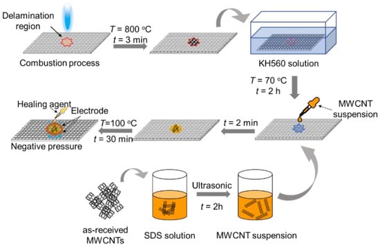
Figure 1.
Schematic of depositing MWCNTs on the CF surface in the repair process.
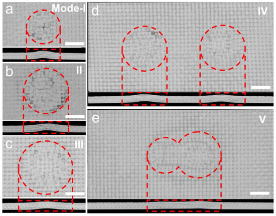
Figure 2.
The CT images of the surface (upper) and cross-section (bottom) of delaminated panels with five different patterns: (a) Mode I; (b) Mode II; (c) mode III; (d) mode IV; (e) mode V. The dashed lines are guides to the eye. The delamination size and pattern shape in five modes are listed in Table S1. Scale bars are 10 mm.
2.2. Monitoring
The repair process, compression tests, and seawater immersion process were in situ monitored by tracking the through-thickness resistance changes in CFRPs, as schematically shown in Figure S2. The copper foil electrodes were placed on the top and bottom surfaces, respectively, and the through-thickness resistance was recorded by a Keithley 2700 programmable electrometer (Tektronix Inc., Beaverton, OR, USA).
2.3. Compression Tests
Compression tests were performed according to ASTM standard, ASTM-D7137M-17, using a universal testing machine (Instron 34TM-30, Canton, OH, USA). The panel was vertically placed on sample holders, and its two edges were fixed by clamps, as shown in Figure S3. The in-plane loading force was exerted at a constant speed of 2 mm/min, and the corresponding stress-strain curve was recorded. The compressive strength of the repaired CFRP panels (σ = F/A) as relative to that of the pristine one (σ0) is used to evaluate the repair efficiency (=σ/σ0), where F and A denote the ultimate compressive force and cross-section area, respectively.
3. Results and Discussion
For CFRP’s practical applications, an efficient repair should hold a high mechanical recovery efficiency at a low time cost. In this sense, we monitored the resin re-construction process and examined the recovery ratio of mechanical properties, as shown in Figure 3. One of the advantages of this repair method is that the curing temperature of the healing agent could be controlled by adjusting the electric resistance heating flowing through the repaired region. Figure 3a shows the central temperature at the upper and bottom surfaces of the repaired region of MWCNT-modified CFRPs as the function of heating duration. In the first 180 s, the central temperature increases sharply and gradually reaches 80 °C at around 400 s. The temperature difference between the upper and bottom surfaces is negligible, and the corresponding in-plane temperature distribution is quite uniform (inset of Figure 3a), which is critical to ensure a homogenous resin solidification in the repaired region.
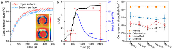
Figure 3.
Monitoring the repair process. (a) The central temperature of the upper and bottom surfaces of repaired region with MWCNTs as a function of heating duration. (b) ∆R/R0 of upper surface of MWCNT-modified CFRPs as the healing agent was injected into the repair region. (c) The compression strength of delaminated CFRPs (mode I, II, III, IV, and V) and corresponding repaired CFRPs with and without MWCNTs.
3.1. Monitoring Resin Construction and Repair Efficiency Evaluation
The whole resin solidification process, including resin permeation and curing, is monitored by a resistance change ratio, ∆R/R0, of the upper surface of CFRPs in Figure 3b, where ∆R = R−R0 is the difference between R at a certain time (t) and the initial R0 at t = 0 s. Due to the introduction of the resin insulator, the ∆R/R0 continuously increases with time until t = ~800 s and then reaches a plateau value. According to the curve shape, we divided the ∆R/R0 time-change into three stages. In the first stage, ∆R/R0 starts to rise when the healing agent is injected into the CFRPs (point A in Figure 3b) and slowly increases to 1 at t = ~500 s (point B in Figure 3b) where the ∆R/R0 of the bottom surface starts to increase, implying that the flowing of resin reaches to the bottom of CFRPs. After that, in the second stage, we applied the pressure on the CFRP to accelerate the permeation of resin, leading to the rapid increase in ∆R/R0 until it reached a plateau value of 5 (point C in Figure 3b). In the third stage, the ∆R/R0 was almost constant, suggesting the resin was fully filled into the CFRP frame. We noted that the ∆R/R0 was independent of curing temperature (Figure S4), and hence we can exclude the temperature effect on the change of ∆R/R0. Hence, we used electric resistance heat to cure the resin in the third stage. In order to calibrate the curing time, we measured the exothermal of the curing process by differential scanning calorimetry in Figure 3b, which suggests that the curing process is completed in 30 min (point D in Figure 3b).
For the repaired CF/epoxy panels, the recovery efficiency is evaluated by its compressive strength as compared to the pristine panels, as shown in Figure 3c. As compared to the pristine panels with compressive strength σ0 = ~168 MPa, the delaminated panels with five modes display a large drop of σ to ~110 MPa. Without MWCNTs modification on the CF surfaces, the recovery efficiency of the repaired panel σ/σ0 is about 65%, while the σ/σ0 significantly increases to ~85% by depositing MWCNTs at the interfaces between CF and the matrix. The stiffness of the MWCNTs-modified-panel is also larger than that of the panels without MWCNTs (Figure S5), suggesting that depositing MWCNTs on the interface could effectively improve the mechanical properties of the repaired CFRPs.
3.2. Monitoring the Compression Process
In order to elucidate the failure origins when the CFRPs are subjected to the compression force, we performed the compression tests on repaired CFRPs with different delamination patterns and monitored their structural changes by MWCNTs-based interfacial-damage sensors in Figure 4. The upper panels in Figure 4 show the force-displacement curves along with the corresponding ΔR/R0 during compression tests for CFRPs with a single circular pattern (mode III, Figure 4a) and two circles being either merged (mode V, Figure 4b) or separated (mode IV, Figure 4c). For all three of the repaired CFRPs, the force linearly increases with displacement until the panel failure occurs, which leads to the force abruptly dropping to zero. The maximum load is almost the same between three repaired panels, while the fracture displacement of mode III is half of that of modes IV and V, suggesting that damage accumulation is much faster in mode III. In contrast to the linearity of load, the ∆R/R0 of panels with one delamination pattern (mode III and mode V) exhibits the distinct two-stage evolution, that is, the ∆R/R0 is almost constant in the first stage and then it sharply increases with displacement until the materials fail. For CFRP with two separated delaminated patterns (mode IV), we measured the ∆R/R0 of each pattern (named A and B) independently, which shows distinctly different changes with displacement. The ∆R/R0 of A shows a two-stage transition, while ∆R/R0 in B continuously decreases with displacement. In the first stage, the steady or slowly increasing ∆R/R0 is expected, which results from the collaborative effect of the denser MWCNTs under compression and the tunneling effect from the deformation. In the second stage, the significant increase in ∆R/R0 signifies the formation of cracks and its fast propagation, leading to failure. For mode IV, the ∆R/R0 transition in pattern B indicates the damage occurring in this region that causes the failure of CFRP, while the decrease in ∆R/R0 of pattern A results from the denser locally connected MWCTNs network in which the structure remains intact. The corresponding front and side images of specimens after compressive tests are shown in the lower panels. We found that the fiber rupture in three modes mostly occurs along the thickness direction and belongs to the shear failure. The failure cracks appear at the boundary of the repaired region, suggesting the brittleness and the weak bonding between the repaired region and the pristine panel. Given that the change of resistance is determined by the connectivity of the interfacial MWCNT network, the proposed monitoring approach shows advantages in monitoring the delamination occurring at the interface, while the damages that do not affect the MWCNTs cannot be sensed.
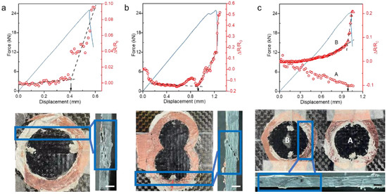
Figure 4.
Compressive tests on repaired panels with (a) mode III, (b) mode V, and (c) mode IV. Upper panels: force and resistance changes (ΔR/R0) with displacement; lower panels: front and side macroscopic damage patterns of repaired panels after compressive tests. Scale bars are 5 mm.
3.3. Monitoring the Seawater Immersion Process
We performed a seawater test to explore the monitoring functions and stability of MWCNTs-modified CFRPs in the humidity environments, as shown in Figure 5a. The pristine and repaired MWCNTs-modified CFRP panels were immersed into the artificial seawater (salinity content of 2.9% and T = 30 °C) for 20 days, the weight change and ΔR/R0 of which were recorded at every 24 h in Figure 5b. For both panels, the water absorption continuously increases and saturates at 12 and 13 days, respectively, which matches the Fickian water absorption rule well [32]. The weight increase in the saturated MWCNTs-modified panel is 0.35 %, which is 2.39 times that of the pristine panel. The larger water absorption suggests that there are more voids in the MWCNTs-modified panel, which are probably introduced in the repair process. The corresponding ∆R/R0 change of the MWCNTs-modified panel with immersion duration resembles the that of the weight changes, that is, ∆R/R0 increases with immersion time, and it reaches a plateau value after immersion for 13 days. The increase in ∆R/R0 is attributed to the tunnel barrier in MWCNTs created by the permeated water molecules. Utilizing the similarity of ∆R/R0 and the weight gain trend with immersion duration, the MWCNTs could serve as weight sensors. The humidity environment has little effect on the compressive strength of the MWCNTs-modified panels. Figure 5c shows that the compression strength is almost invariant at immersion durations of 0, 6, 12, and 20 days; the corresponding load-displacement curves are shown in Figure 5d. The stable compression strength of repaired MWCNTs-modified samples benefits from the coupling agent and MWCNTs, which bridge CF and the matrix by forming strong covalent bonds and multiple interlocking [33]. This strengthening mechanism is resistant to the humidity environment. The shear surface morphology of the MWCNTs-modified panel after being immersed for 480 h is shown in Figure 5e, which clearly shows a significant amount of resin left on the CF surface after compressive damage, implying a brittle fracture feature of damages. The high mechanical performance of MWCNTs-modified panels in seawater suggests their robustness in humid environments.
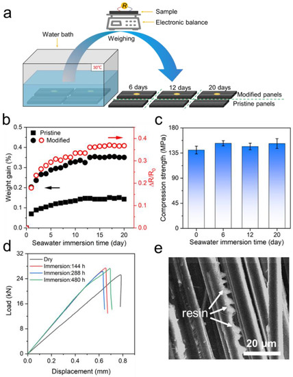
Figure 5.
Seawater immersion monitoring and mechanical performance. (a) Schematic of seawater-immersion experiment. (b) Weight gain and ∆R/R0 of the MWCNT-modified panel as a function of seawater-immersion time. The squares and circles denote the pristine and modified samples, respectively. The symbols in black and red colors belong to the weight gain and ∆R/R0 (guided by the arrows), respectively. (c) Compressive strength of wetted panels as the function of seawater-immersion time. (d) Compressive load-displacement curves of panels immersed in seawater for different duration. (e) SEM images of the shear surface after compression and immersion for 20 days.
As typical non-destructive testing methods, nonlinear ultrasound and X-ray CT have unique advantages but also limitations in terms of accuracy and reliability. Regarding the former, its propagation could penetrate a certain depth of materials and hence inspect the structure in a qualitative way. However, accuracy and reliability are limited by polymer-based materials because of the high attenuation of ultrasound caused by the polymer viscoelasticity [34]. Moreover, a full structural inspection requires multiple scans with different incident angles, and the corresponding angle-dependent velocity corrections may impair the accuracy [35]. Regarding the latter, it can achieve high-resolution detection; however, its accuracy relies heavily on the quality of reconstructed volume images, which, in turn, depend on many parameters specified by the operator [36]. In contrast, the proposed method directly implants the damage sensors at the interface between two phases, the signal of which is barely interfered with by the environmental factors and hence displays high sensitivity and accuracy. The stability of sensors ensures the reliability of the sensing approach.
4. Conclusions
This paper presents the combined delamination repair and in situ monitoring of CFRP panels by depositing MWCNT damage sensors at the interface between CF and matrix. Sequential experimental research consists in the in-situ repair of delamination damage, compression tests, and the seawater immersion of MWCNTs-modified CFRP specimens. In-situ monitoring was performed during the above experiments to understand the failure mechanisms and effectiveness of the repair. The main conclusions are summarized as follows:
Due to the collaborative effect of KH560 and MWCNTs, the compressive strength of repair panels recovers to ~145 MPa regardless of the delamination size and patterns. The recovery efficiency of these panels reaches 85% compared with unmodified panels with an efficiency of 65%.
The compressive strength of the modified panel is invariant after immersion in seawater for as long as 480 h. Within the maximum seawater immersion duration of 480 h, the mechanical performance of the MWCNTs-modified panels was not affected by resin plasticization.
Regarding the damage sensors, the ΔR/R0 of MWCNTs-modified CFRPs could effectively monitor the resin injection, permeation, and solidification processes. The ΔR/R0 evolution with displacement shows a distinct crack occurring and propagation development, which cannot be recognized in its load-displacement curves. Moreover, the ΔR/R0 could index the weight changes in the immersion experiments.
Supplementary Materials
The following supporting information can be downloaded at https://www.mdpi.com/article/10.3390/en15228348/s1, Figure S1: the high-resolution scanning electron microscopy image of MWCNTs; Figure S2: the schematic of in situ monitoring in repair process (a) and compression tests (b); Figure S3: the clamping mode of CFRPs in compression tests; Figure S4: ∆R/R0 as a function of curing temperature of the repaired panel; Figure S5: the load-displacement curve of the repaired panels in the compression test. (a) Mode I; (b) mode II; (c) mode III; (d) mode IV; (d) mode V; and Table S1: the delamination size and pattern shape.
Author Contributions
Conceptualization, Y.C. and B.Y.; methodology, W.H.; formal analysis, W.H. and B.Y.; investigation, W.H., Z.S., L.Y., S.Z., F.W. and Y.C.; writing—original draft preparation, Y.C., B.Y. and W.H.; writing—review and editing, Y.C. and B.Y.; visualization, W.H., Z.S., L.Y., S.Z. and Y.C.; supervision, Y.C.; and project administration: Y.C. and B.Y. All authors have read and agreed to the published version of the manuscript.
Funding
This research was funded by the National Natural Science Foundation of China (12072238, 12222206, and 12102304); the Shanghai Rising-Star Program (22QA1409500); the Shanghai Pujiang Program (grant no. 20PJ1413800); and the Natural Science Youth Funds of Jiangsu Province, China (BK20220554).
Data Availability Statement
The original contributions presented in the study are included in the article/Supplementary Material; further inquiries can be directed to the corresponding authors.
Conflicts of Interest
The authors declare no conflict of interest.
References
- Ren, L.; Kang, L.; Niu, H.; Guo, H.; Lv, R.; Bai, S.L.; Li, M. Structural optimization design of CFRP with ultrahigh in-plane thermal conductivity and mechanical strength. Compos. Part A 2022, 163, 107209. [Google Scholar] [CrossRef]
- Pu, Y.; Ma, Z.; Liu, L.; Bai, Y.; Huang, Y. Improvement on strength and toughness for CFRPs by construction of novel “soft-rigid” interface layer. Compos. Part B 2022, 236, 109846. [Google Scholar] [CrossRef]
- Takamoto, K.; Ogasawara, T.; Kodama, H.; Mikami, T.; Oshima, S.; Aoki, K.; Yokozeki, T. Experimental and numerical studies of the open-hole compressive strength of thin-ply CFRP laminates. Compos. Part A 2021, 145, 106365. [Google Scholar] [CrossRef]
- Katagiri, K.; Honda, S.; Nakaya, S.; Kimura, T.; Yamaguchi, S.; Sonomura, H.; Sasaki, K. Tensile strength of CFRP with curvilinearly arranged carbon fiber along the principal stress direction fabricated by the electrodeposition resin molding. Compos. Part A 2021, 143, 106271. [Google Scholar] [CrossRef]
- Wang, Z.; Zhao, M.; Liu, K.; Yuan, K.; He, J. Experimental analysis and prediction of CFRP delamination caused by ice impact. Eng. Fract. Mech. 2022, 273, 108757. [Google Scholar] [CrossRef]
- Wei, L.; Chen, J. Characterization of delamination features of orthotropic CFRP laminates using higher harmonic generation technique: Experimental and numerical studies. Compos. Struct. 2022, 285, 115239. [Google Scholar] [CrossRef]
- Calvo, J.V.; Feito, N.; Miguélez, M.H.; Giner, E. Modeling the delamination failure under compressive loads in CFRP laminates based on digital image correlation analysis. Compos. Struct. 2022, 287, 115265. [Google Scholar] [CrossRef]
- Moreira, R.D.F.; De Moura, M.F.S.F.; Silva, F.G.A.; Reis, J.P. High-cycle fatigue analysis of adhesively bonded composite scarf repairs. Compos. Part B 2020, 190, 107900. [Google Scholar] [CrossRef]
- Liu, X.; Wang, G. Progressive failure analysis of bonded composite repairs. Compos. Struct. 2007, 81, 331–340. [Google Scholar] [CrossRef]
- Sun, C.; Zhao, W.; Zhou, J.; Altenaiji, M.; Cantwell, W.J.; Wang, Q.Y.; Guan, Z.W. Mechanical behaviour of composite laminates repaired with a stitched scarf patch. Compos. Struct. 2021, 255, 112928. [Google Scholar] [CrossRef]
- Mohammadi, M.A.; Eslami-Farsani, R.; Ebrahimnezhad-Khaljiri, H. Experimental investigation of the healing properties of the microvascular channels-based self-healing glass fibers/epoxy composites containing the three-part healant. Polym. Test 2020, 91, 106862. [Google Scholar] [CrossRef]
- Nguyen, A.T.; Orifici, A.C. Structural assessment of microvascular self-healing laminates using progressive damage finite element analysis. Compos. Part A 2012, 43, 1886–1894. [Google Scholar] [CrossRef]
- Gong, L.; Feng, J.; Zhou, P.; Zhou, F.; Jiang, Y.; Feng, Y. Mechanics mechanism of slab-type short bolt composite structure for repairing cracked lining under compression shear. Eng. Fail Anal. 2022, 142, 106765. [Google Scholar] [CrossRef]
- Joosten, M.W.; Neave, M.B.; Rider, A.N.; Varley, R.J. 3D printed continuous fibre composite repair of sandwich structures. Compos. Struct. 2022, 290, 115518. [Google Scholar] [CrossRef]
- Psarras, S.; Loutas, T.; Galanopoulos, G.; Karamadoukis, G.; Sotiriadis, G.; Kostopoulos, V. Evaluating experimentally and numerically different scarf-repair methodologies of composite structures. Int. J. Adhes. Adhes. 2020, 97, 102495. [Google Scholar] [CrossRef]
- Fardnam, A.P.; Maleki, A.; Najafabadi, M.A. Investigation of buckling of laminated composites repaired by resin injection using acoustic emission and cohesive zone simulation method. Compos. Struct. 2022, 298, 116008. [Google Scholar] [CrossRef]
- Min, S.; Chen, X.; Chai, Y.; Lowe, T. Effect of reinforcement continuity on the ballistic performance of composites reinforced with multiply plain weave fabric. Compos. Part B 2016, 90, 30–36. [Google Scholar] [CrossRef]
- Sathler, J.F.; de Luca, C.R.; dos Reis, J.M.L.; da Costa Mattos, H.S. Alternative methods for fracture energy acquisition in the qualification of composite repair system. Compos. Struct. 2021, 258, 113420. [Google Scholar] [CrossRef]
- Li, Y.; Wei, Y.; Meng, J.; Zhang, L.; Wang, P.; Zheng, H.; Lei, H. Damage evolution characterization of glass fabric composites at cryogenic temperatures via in-situ tensile X-ray computed tomography tests. Compos. Commun. 2022, 35, 101326. [Google Scholar] [CrossRef]
- Alnuaimi, H.; Amjad, U.; Park, S.; Russo, P.; Lopresto, V.; Kundu, T. An improved nonlinear ultrasonic technique for detecting and monitoring impact induced damage in composite plates. Ultrasonics 2022, 119, 106620. [Google Scholar] [CrossRef]
- Meola, C.; Boccardi, S.; Carlomagno, G.M.; Boffa, N.D.; Ricci, F.; Simeoli, G.; Russo, P. Impact damaging of composites through online monitoring and non-destructive evaluation with infrared thermography. NDT E Int. 2017, 85, 34–42. [Google Scholar] [CrossRef]
- Wang, X.; Lu, J.; Lu, S.; Li, B.; Zhang, L.; Ma, C.; Yang, B. Health monitoring of repaired composite structure using MXene sensor. Compos. Commun. 2021, 27, 100850. [Google Scholar] [CrossRef]
- Wang, X.; Li, B.; Zhang, D.; Lu, J.; Lin, L.; Lu, S.; Yang, B. Strain monitoring using carbon nanotube Buckypaper sensor on composite repaired structure. Appl. Phys. A 2021, 127, 935. [Google Scholar] [CrossRef]
- Stojcevski, F.; Hayne, D.J.; Hilditch, T.B.; Henderson, L.C. Investigating interfacial adhesion and open-hole compressive (OHC) strength correlations for CFRPs via variations in sizing and oxidative surface treatment. Compos. Part A 2021, 150, 106587. [Google Scholar] [CrossRef]
- Pramanik, C.; Nepal, D.; Nathanson, M.; Gissinger, J.R.; Garley, A.; Berry, R.J.; Heinz, H. Molecular engineering of interphases in polymer/carbon nanotube composites to reach the limits of mechanical performance. Compos. Sci. Technol. 2018, 166, 86–94. [Google Scholar] [CrossRef]
- Yang, B.; Xuan, F.Z.; Lei, H.; Wang, Z.; Xiang, Y.; Yang, K.; Liang, W. Simultaneously enhancing the IFSS and monitoring the interfacial stress state of GF/epoxy composites via building in the MWCNT interface sensor. Compos. Part A 2018, 112, 161–167. [Google Scholar] [CrossRef]
- Yang, B.; Xuan, F.Z.; Wang, Z.; Chen, L.; Lei, H.; Liang, W.; Yang, K. Multi-functional interface sensor with targeted IFSS enhancing, interface monitoring and self-healing of GF/EVA thermoplastic composites. Compos. Sci. Technol. 2018, 167, 86–95. [Google Scholar] [CrossRef]
- Zhao, T.; Jiang, Y.; Zhu, Y.; Wan, Z.; Xiao, D.; Li, Y.; Fang, D. An experimental investigation on low-velocity impact response of a novel corrugated sandwiched composite structure. Compos. Struct. 2020, 252, 112676. [Google Scholar] [CrossRef]
- Thunga, M.; Bauer, A.; Obusek, K.; Meilunas, R.; Akinc, M.; Kessler, M.R. Injection repair of carbon fiber/bismaleimide composite panels with bisphenol E cyanate ester resin. Compos. Sci. Technol. 2014, 100, 174–181. [Google Scholar] [CrossRef]
- Balakrishnan, V.S.; Seidlitz, H. Potential repair techniques for automotive composites: A review. Compos. Part B 2018, 145, 28–38. [Google Scholar] [CrossRef]
- Cang, Y.; Hu, W.; Zhu, D.; Yang, L.; Hu, C.; Yuan, Y.; Yang, B. In situ thermal ablation repair of delamination in carbon fiber-reinforced thermosetting composites. Energies 2022, 15, 6927. [Google Scholar] [CrossRef]
- Al-Hajaj, Z.; Zdero, R.; Bougherara, H. Mechanical, morphological, and water absorption properties of a new hybrid composite material made from 4 harness satin woven carbon fibres and flax fibres in an epoxy matrix. Compos. Part A 2018, 115, 46–56. [Google Scholar] [CrossRef]
- Hu, W.; Sun, Z.; Yang, L.; Hu, C.; Zhang, S.; Wang, F.; Cang, Y. Interfacial Strengthening and Self-Monitoring in Carbon Fiber-Reinforced Composites via Carbon Nanotube-Based Damage Sensors. Nanomaterials 2022, 12, 3717. [Google Scholar] [CrossRef]
- Zhang, Z.; Li, Q.; Liu, M.; Yang, W.; Ang, Y. Through transmission ultrasonic inspection of fiber waviness for thickness-tapered composites using ultrasound non-reciprocity: Simulation and experiment. Ultrasonics 2022, 123, 106716. [Google Scholar] [CrossRef] [PubMed]
- Zardan, J.P.; Gueudré, C.; Corneloup, G. Study of induced ultrasonic deviation for the detection and identification of ply waviness in carbon fibre reinforced polymer. NDT E Int. 2013, 56, 1–9. [Google Scholar] [CrossRef]
- Zhang, X.; Sun, L.; Wang, B.; Pan, B. Effect of the number of projections in X-ray CT imaging on image quality and digital volume correlation measurement. Measurement 2022, 194, 111061. [Google Scholar]
Publisher’s Note: MDPI stays neutral with regard to jurisdictional claims in published maps and institutional affiliations. |
© 2022 by the authors. Licensee MDPI, Basel, Switzerland. This article is an open access article distributed under the terms and conditions of the Creative Commons Attribution (CC BY) license (https://creativecommons.org/licenses/by/4.0/).