Article

Thermal Performance Analysis on the Seasonal Heat Storage by Deep Borehole Heat Exchanger with the Extended Finite Line Source Model

1
College of Environmental Science and Engineering, Donghua University, Shanghai 201620, China
2
Lily Group Co., Ltd., Hangzhou 311228, China
3
Institute of Refrigeration and Cryogenics, Zhejiang University, Hangzhou 310027, China
4
Key Laboratory of Refrigeration and Cryogenic Technology of Zhejiang Province, Hangzhou 310027, China
5
Zhejiang Key Laboratory of Clean Energy and Carbon Neutrality, Hangzhou 310027, China
6
CNNP Kunhua Energy Development Co., Ltd., Hangzhou 311113, China
7
Shanghai Zhongsheng Carbon Technology Co., Ltd., Shanghai 200331, China
*
Author to whom correspondence should be addressed.
Energies 2022, 15(22), 8366; https://doi.org/10.3390/en15228366
Submission received: 9 September 2022 / Revised: 12 October 2022 / Accepted: 5 November 2022 / Published: 9 November 2022
(This article belongs to the Special Issue New Advances in Rock Mechanics and Underground Thermal Energy Storage)

Abstract

:
Deep borehole heat exchanger is promising and competitive for seasonal heat storage in the limited space underground with great efficiency. However, seasonal heat storage performance of the essentially deep borehole heat exchanger reaching kilometers underground was seldom studied. In addition, previous research rarely achieved comprehensive assessment for its thermal performance due to seasonal heat storage. Insight into the complicated heat transfer characteristics during the whole process of prior charging and subsequent discharging of deep borehole heat exchanger is in urgent need to be clarified. To this end, an extended finite line source model is proposed to investigate thermal performance of the deep borehole heat exchanger during charging and discharging stages. It is developed with modifications of classical finite line source model to consider the spatio-temporally non-uniform distribution of heat flux density and anisotropic thermal conductivity of deep rock. In general, simulation results demonstrate that thermal performance of the deep borehole heat exchanger deteriorates rapidly both during charging and discharging stages, making it impossible to sustain long-term efficient operation. Specifically, it was discovered that low temperature heat storage utilized only upper section of the borehole as effective heat storage section, and enhancement for heat extraction potential during the heating season was not significant. While high temperature heat storage by deep borehole heat exchanger could only enhance the heat extraction potential for 30 to 40 days in the initial stage of heating. Throughout the discharging, maximum thermal performance enhancement up to 11.27 times was achieved and the heat storage efficiency was evaluated at 2.86 based on average heat exchange rate. The findings of this study are intended to provide a guidance for decisionmakers to determine the most suitable seasonal heat storage strategy for the deep borehole heat exchanger and facilitate the application in engineering practice.

1. Introduction

Deep borehole heat exchanger (DBHE) shows great prospect in exploitation of deep geothermal energy and has attracted increasing attention in recent years [1,2,3,4,5,6,7,8,9]. Compared with traditional shallow BHEs, DBHE is featured with much deeper drilling depth underground, which could reach up to 1000~3000 m. This geothermal technology allows for efficient utilization of underground space with small footprint, and it can extract deep geothermal energy underground on a larger temperature range from 40 °C to 80 °C [3,6]. Despite of the appealing merits for real application, heat extraction efficiency of DBHE need to be improved [10,11,12]. Numerical simulations and field test proved that traditional single heat extraction by DBHE without surplus heat supplement will result in considerable temperature decrease of rock mass in the vicinity of borehole [11,12]. Thus, its thermal performance would gradually deteriorate with operation time. In order to maintain sustainable operation of DBHE on cyclic year by year, proper seasonal heat storage is necessary [13,14,15,16], especially in cold climate areas where heating load is usually higher than cooling.
Although seasonal heat storage stands as one feasible option to sustain long-term operation of DBHE, heat storage via DBHE is a relatively new approach in the field of borehole thermal energy storage (BTES). Up to now, underground thermal energy storage is mostly limited to shallow BHEs or aquifers [17,18], while related research and engineering practice based on DBHE are in scarce and there are no systematic operational experiences yet [8,19]. Kristian presented a coupled geothermal-solar thermal case study in crystalline bedrock based on medium deep BTES for an office building by storing excess heat from solar panels or thermal power stations of more than 110 °C in summer [20]. Feasibility as well as design criteria of the thermal energy storage system were schematically discussed in the study. But drilling depth of the boreholes in study ranged from 105 m to 500 m. They are not so deep essentially, heat storage potential of DBHE has not been fully explored. In order to gather virtual experiences with medium deep borehole thermal energy storage systems, Schulte presented the MATLAB-based Borehole Heat Exchanger Array Simulation and Optimization (BASIMO) tool [8]. This simulator can numerically simulate and optimize the three-dimensional design of a deep BTES system, which lays solid foundation for construction proposal of a pilot facility.For the sake of optimization on the deep BTES system, Bastian et al. analyzed the influence of characteristic design parameters like borehole layout, fluid inlet temperatures and properties of the reservoir rock on the thermal performance [19]. According to their simulation results, several GWh of thermal energy can be stored during summer and extracted during the heating period. It was also discovered that the promising large-scale deep BTES system can operate cyclically with a high recovery rate of up to 83% [19]. On account of the transient strong heat flux around the borehole of deep BTES system under high temperature charging and discharging conditions [21,22,23,24,25], it poses great challenge to perform robust simulation of the extreme heat transfer process. To address this problem, Zhao et al. formulated a highly efficient heat transfer model to depict the transient evolution of outlet temperature and heat flux density along borehole depth [26]. Moreover, practical monitoring and in-situ field test have also been conducted to validate and calibrate the model in the study.
In general, prior heat transfer simulation of it during charging and discharging is indispensable to grasp a comprehensive understanding of the transient thermal performance of deep BTES system and the dynamic heat transfer characteristics. However, it is found that there exist three shortcomings from the literature review above. Firstly, researchers usually focused on the high temperature heat storage strategy in maximizing the heat extraction output and heat storage efficiency [8,19,20], and highlighted the advantages of the high temperature heat storage. Whereas, thermal performance by low temperature heat storage has not been investigated yet, which displays distinctively different characteristics from high temperature. Secondly, previous simulated deep BTES system is mostly limited to medium deep borehole depth [8,19,20]. However, seasonal heat storage performance of the essentially deep borehole heat exchanger reaching kilometers underground was seldom studied. Thirdly, in previous research, only one or two indicators of the thermal performance are generally discussed, especially outlet temperature and storage efficiency, which lead to narrower conclusions [19,20].
In order to achieve full utilization of surplus heat production and further incentivize multi-energy complement with the deep geothermal energy available underground, it is crucial to evaluate the seasonal heat storage performance with overall considerations of the transient thermal performance aspects. It contributes to a clear knowledge of the thermal response characteristics for the sake of optimal design and operation of deep BTES system. This paper is organized as following: Firstly, heat transfer model for the deep BTES system is proposed to perform thermal analysis in Section 2. This model highlights unsteady state heat transfer in the rock and quasi-steady state heat transfer inside the borehole of DBHE. As for unsteady state heat transfer in the rock, an extended finite line source model (EFLS) is applied for the simulation. EFLS originates from the classical finite line source model (FLS) and adopts the superposition principle to model the spatio-temporal step heat impulses. EFLS is comprehensively developed with modifications to consider the non-uniform distribution of heat flux density along borehole depth and anisotropic thermal conductivity of rock segments typical of the deep borehole. With respect to heat transfer inside the borehole, both heat storage and heat extraction modes of the deep BTES system are formulated with the analytical temperature profiles of circulating water along depth in detail. Section 3 presents evaluation indicators for seasonal heat storage followed by Section 4 where thermal performance and dynamic heat transfer characteristics of the deep BTES system during charging and discharging stages are investigated. Key parameters are simulated to evaluate the thermal performance of deep BTES, including spatio-temporal distribution of heat flux density and temperature profile of circulating flow along depth, rock temperature field evolution, variation of outlet temperature as well as heat storage and heat extraction rates with operation time. Section 5 further discusses advantages and disadvantages of the study. Finally, Section 6 concludes with a summary pointing future work for the deep BTES system.

2. Heat Transfer Modeling for the Deep BTES System

For the design of a deep BTES system, two separate stages including charging and discharging should be considered respectively. Schematic of charging during summer and discharging during winter by DBHE is described in Figure 1. In this section, a generic and efficient heat transfer model is developed for DBHE underground, which is the core heat transfer component of the deep BTES system.
Heat transfer analysis of DBHE includes rock temperature evolution outside the borehole and temperature profile of the circulating fluid along depth in the inner and outer branches of the coaxial tube installed inside the borehole [23,24]. In the rock zone, three-dimensional unsteady heat transfer evolves within large spatio-temporal scales range in the radial and axial directions, and it is coupled with the quasi-steady heat conduction within the borehole through complex boundary conditions. As a matter of fact, it is rather computationally demanding to perform thermal analysis of DBHE [9,12,22,27,28]. This model highlights both analytical formulations for thermal response inside and outside the deep borehole, which is featured with great simulation convenience and efficiency. As for unsteady heat transfer in the rock zone, thermal response due to the complicated heat impulses during charging and discharging is comprehensively formulated on the basis of extended finite line source model and superposition principle. With respect to heat transfer inside the borehole, both heat storage and heat extraction modes of the deep BTES system are presented in detail.

2.1. Model Assumptions

For simplicity of the heat transfer simulation, four aspects are taken into account regarding the model assumptions: (1) Despite of the real geological setting that rock is segmented layer by layer vertically, there exists minor difference in terms of the thermo-physical parameters. Therefore, rock around the deep borehole could be considered as homogeneous medium. (2) Compared to the drilling depth of borehole and the surrounding rock mass, borehole diameter in engineering is very small (100~200 mm), so its radial scale could be safely ignored. BHE inside the borehole is usually described as a one-dimensional line heat source, while the whole rock mass outside the borehole is regarded as semi-infinite medium. (3) Groundwater flow is decreasing with depth, making conduction the dominant heat transport process. Therefore, Heat storage underground avoids conflict with groundwater use. (4) Rock temperature underground increases with the geothermal gradient, and the temperature fluctuation beneath the shallow subsurface is ignored in view of the extreme deep drilling depth of the borehole.

2.2. Unsteady Heat Transfer Analysis outside the Deep Borehole

When performing heat transfer analysis for borehole heat exchangers, the simulation zone involved can be generally divided into two parts [23,24,29]: rock zone outside the borehole and backfill zone inside the borehole (including the heat exchanger branch pipes and backfill material). The two subzones are analyzed with different simplifications using the borehole wall as interface. Rock temperature outside borehole evolves dramatically during the operation, thus having a significant impact on the heat transfer condition of DBHE. Unsteady heat transfer model is required to depict the transient charging or discharging in the rock, especially under long-term operation [25,30].

2.2.1. Green Function for Transient Thermal Response in the Rock

Thermal response in the rock due to dynamic heat release or extraction of the borehole heat exchanger is generally simulated on the basis of Green function for transient point heat sources or sinks and superposition principle [23,24,29,30]. Green function is widely applied in heat transfer modeling of borehole heat exchanger, which also referred to the heat source function [24,30]. It holds under zero initial condition and specific boundary conditions. Carslaw and Jaeger first derived the classical thermal response solution due to a transient point heat source for the pure heat conduction problem [31].
G ( x , y , z , τ ; x , y , z , τ ) = 1 [ 4 π a s ( τ τ ) ] 3 exp ( ( x x ) 2 + ( y y ) 2 + ( z z ) 2 4 a s ( τ τ ) )
where, a s = λ s / ρ s c s denotes rock thermal diffusion coefficient, while λ s , ρ s , and c s are the heat conductivity, density, and specific heat capacity of rock, respectively. The first part ( x , y , z , τ ) in Green function G ( x , y , z , τ ; x , y , z , τ ) for transient point heat source represents location of the rock element at ( x , y , z ) and thermal response time at τ . The second part ( x , y , z , τ ) denotes location of the transient point heat impluse, which was released at time τ . Overall surplus temperature field due to various complex heat sources (e.g., nonlinear boundary conditions or temporal heat source terms) could be obtained by successively superimposing the contributions of multiple transient heat impulses released at different time prior [24,30]. This is the basic idea of Green function approach for solving unsteady state heat conduction problem.

2.2.2. Finite Line Heat Source Model

To obtain the overall thermal response underground, DBHE inside the borehole could be discretized into several vertical segments that act as a series of point heat sources along borehole depth. In view of the linear characteristics of the problem, Green function applies to integrate thermal response of the scattered point heat sources. Specifically, if these vertically distributed point heat sources continuously release heat from τ = 0 to τ = τ , then thermal response at time τ for the rock element located at ( x , y , z ) reads as:
θ ( x , y , z , τ ) = 1 ρ s c s 0 τ d τ 0 H q l ( z ) 8 [ π a s ( τ τ ) ] 3 exp ( ( x x ) 2 + ( y y ) 2 + ( z z ) 2 4 a s ( τ τ ) ) d z
where q l ( z ) indicates heat flux density distribution of borehole heat exchanger along depth, H is the drilling depth of borehole. θ ( x , y , z , τ ) denotes the surplus rock temperature, which is defined as:
θ ( x , y , z , τ ) = T s ( x , y , z , τ ) T i n i t ( x , y , z , τ )
Here, T s ( x , y , z , τ ) represents the instant temperature, while initial rock temperature underground T i n i t ( x , y , z , τ ) is taken as the reference.
This formulation for rock thermal response is referred to as infinite line heat source model in the literature [23,24]. It is worth noting that ground surface boundary constraint and the finite borehole depth are not reasonably considered in Equation (2). Rock temperature would not stabilize with operation time. Therefore, it cannot be directly applied to study long-term heat transfer of borehole heat exchangers [32]. In order to address the shortcomings of infinite line heat source model, Eskilson developed a finite line heat source model [32,33,34,35]. The finite line heat source model regards the rock zone as semi-infinite medium and properly takes into account the finite drilling depth characteristics. To model the ground surface condition, this model utilizes two types of line heat sources. One is the real finite line heat source perpendicular to the subsurface boundary with the heat flux intensity of q l ( z ) along depth. The other is a virtual line heat sink, which is set up above the ground surface with the heat flux intensity of q l ( z ) . It shares the same length and symmetrical to the real line heat source about the boundary. Using the Green function, thermal response at time τ for the point ( x , y , z ) could be evaluated by superposition of the surplus temperatures resulting from both the line heat source and the virtual heat sink as:
θ ( x , y , z , τ ) = 1 ρ s c s 0 τ d τ 0 H q l ( z ) 8 [ π a s ( τ τ ) ] 3 exp ( ( x x ) 2 + ( y y ) 2 4 a s ( τ τ ) ) [ exp ( ( z z ) 2 4 a s ( τ τ ) ) exp ( ( z + z ) 2 4 a s ( τ τ ) ) ] d z

2.2.3. Extended Finite Line Heat Source Model

Although heat transfer in the rock zone outside the borehole could be stably simulated by the classical finite line source solution, it mainly applies for shallow borehole heat exchangers, where borehole wall temperature and heat flux density are simply regarded as constant along depth [33,35]. However, DBHE has distinctively different heat transfer characteristics from shallow borehole heat exchangers, since borehole wall temperature and the heat flux density along the extreme deep borehole are not uniformly distributed any more but evolving spatially and temporally throughout the operation [12,22,26]. Moreover, the deep rock displays complicated anisotropic heat conduction effect [36], which should also be properly considered. To this end, classical finite line heat source model needs to be further modified to account for the non-uniform distribution of heat flux density of DBHE (shown in Figure 2) and anisotropic heat conduction of deep rock. In this section, an extended finite line heat source model (EFLS) that could describe the dynamic heat transfer of deep BTES system under both heat storage and heat extraction conditions is proposed.
EFLS constructs the corresponding Green function for thermal response in the rock by taking advantage of its multi-dimensional independent characteristics. Consequently, thermal response in the rock zone outside the deep borehole due to transient heat flux of DBHE could be formulated as:
θ ( x , y , z , τ ) = 1 4 π λ s x λ s y 0 H q l ( z ) ( e r f c ( r a n i s o 2 a s z τ ) r a n i s o e r f c ( r + a n i s o 2 a s z τ ) r + a n i s o ) d z
Noticeably, r a n i s o and   r + a n i s o are the equivalent relative distances between the location of the rock element to be simulated and the point heat source as well as the virtual heat sink respectively. They are mathematically determined as:
r a n i s o = λ z x ( x x ) 2 + λ z y ( y y ) 2 + ( z z ) 2
r + a n i s o = λ z x ( x x ) 2 + λ z y ( y y ) 2 + ( z + z ) 2
where λ s x , λ s y , λ s z are the anisotropic heat conductivities of rock in the respective directions, a s x , a s y and a s z are the corresponding thermal diffusion coefficients. While λ z x = λ s z / λ s x , λ z y = λ s z / λ s y are the ratio between the respective thermal conductivity coefficients. This thermal response solution also applies for isotropic heat conduction, which is a special case of anisotropic heat transfer.
Up to now, thermal response solution for DBHE has already been presented except for the distribution of heat flux density along depth which is left to be determined. In previous study we have revealed the heat flux density distribution law of DBHE under continuous heat extraction condition with constant inlet temperature and mass flow rate [12], which reads as:
q l ( z ) = 2 π λ s ( r 2 r b 2 ) ( T s ( z ) + F l u x ( z , τ ) π ( r 2 r b 2 ) ρ s c s T f 1 ( z ) ) r 2 ln r r b 1 2 r 2 + 1 2 r b 2 + 2 π λ s R b ( r 2 r b 2 )
However, it is not flexible enough for real applications especially the transient varying charging and discharging conditions of deep BTES system concerned in this study. Moreover, this formulation ignores anisotropic heat conduction of deep rock.

2.2.4. Superposition Principle of Step Heat Impulses

Since the heat flux density evolves drastically both in spatial and temporal dimensions, it could only be evaluated numerically by coupling transient heat transfer conditions inside and outside the borehole rather than manually assumed. Given the instant temperature distributions of borehole wall and the circulating flow in the annulus of the coaxial DBHE, instant heat flux density along borehole depth could thus be updated as:
q l ( z ) = T f 1 ( z ) T b ( z ) R 11
Here, R 11 is the thermal resistance between annulus of DBHE and borehole wall, which could be calculated by Equation (11) in Section 2.3.1. While instant borehole temperature T b could be determined by Equation (5) given the borehole radius and heat flux at the prior moment. It should be noted that due to anisotropic heat conduction modeling as shown in Equations (6) and (7), the effective borehole temperature for heat transfer should be averaged circumferentially.
Equation (9) offers spatial distribution of heat flux density along borehole depth at a given moment. On the other hand, the heat flux density witnessed a dramatic evolution during the whole operation of heat storage and extraction of deep BTES system. Overall thermal response of the rock outside the borehole at a given moment could be evaluated by superposition of the series of variable heat impulses (each represents a constant step heat impulse at different previous action moment). Based on superposition principle for step-variable heat impulses [24,30] and the extended finite line heat source model, surplus temperature for any rock element could be determined as following:
θ i ( r , z , τ ) = j = 1 n E F L S ( q i , j q i , j 1 , τ τ j )
where E F L S denotes the extended finite line heat source model, q i , j is the magnitude of heat flux intensity of the line heat source i at time   τ j . For any time τ j = τ 0 + j Δ τ , Δ τ is the time step of heat transfer simulation for the deep BTES system. τ 0 and   τ n are the initial and ending time for the heat impulse action.
This approach takes advantage of analytical solution to quantitatively describe the transient heat transfer of deep BTES system. It could accurately characterize thermal response of rock element at arbitrary spatial location with adaptive temporal resolution on the hourly, daily or monthly basis as shown in Figure 3. More importantly, computational overhead is greatly reduced in comparison with traditional numerical method. Therefore, cumulative effect of the long-term charging or discharging of deep BTES system could be efficiently depicted without resort to solving large heat transfer equations set.

2.3. Quasi-Steady State Heat Transfer inside the Deep Borehole

This section performs thermal analysis for the dynamic heat transfer within the borehole of DBHE operating under heat storage and heat extraction conditions as shown in Figure 4. As heat carrier, circulating water could either flow downward in the inner pipe and out of the annulus (heat storage) or downward in the annulus of coaxial tube and out of the inner pipe (heat extraction). As mentioned above, radial heat transfer effect inside the borehole could be ignored in view of the small radius ratio to drilling depth. Therefore, the coaxial heat exchanger inside borehole is suitable to be regarded as a deep axial line. One-dimensional quasi-steady state heat transfer model could be adopted to establish the thermal balance [37,38].

2.3.1. Thermal Balance Analysis and Thermal Resistance for the One-Dimensional Heat Transfer

Figure 5 illustrates the thermal circuit of the coaxial annular borehole heat exchanger, which is widely applied for simplicity of heat transfer analysis in literature [39,40]. Local heat flux between the annulus and the borehole wall as well as that between the annulus and the inner pipe could be calculated on the basis of the relative temperature difference respectively [39]. Hence corresponding thermal resistances are easily formulated:
R 11 = 1 2 π λ b ln r b r o o + 1 2 π λ p o ln r o o r o i + 1 2 π r o i h f o
R 12 = 1 2 π λ p i ln r i o r i i + 1 2 π r i o h f o + 1 2 π r i i h f i
where R 11 is the thermal resistance between annulus and borehole wall, and R 12 denotes the thermal resistance between inner pipe and annulus. r o o and r o i are the outer and inner diameters of the annulus respectively, while r i o and r i i are the outer and inner diameters of the inner pipe. r b denotes the borehole radius. In addition, λ b , λ p o and λ p i are the thermal conductivities of backfill material, annulus and inner pipe of the coaxial heat exchanger each other. h i and h o represent the convective heat transfer coefficients of circulating fluid to the inner pipe and the annulus wall, respectively.
Depending on specific flowing condition, the convective heat transfer coefficients can be determined according to the Nusselt number [24,29]:
h f = λ f d N u
where, λ f is the thermal conductivity of the working fluid, d is the diameter of the circular tube. The Nusselt number N u is related with the Reynolds number R e and Prandtl number P r of the circulating fluid as [24,29]:
N u = 0.023 R e 0.8 P r 0.33

2.3.2. Heat Storage Model during Charging

Under the heat storage condition, inner pipe serves as the inlet for high temperature circulating water. As depicted in Figure 4, due to the temperature difference between the circulating water in the annulus relative to the borehole wall and the inner pipe, heat flow exists between both branch pipes as well as between the annulus and the borehole wall. Thus, quasi-steady state thermal balance would build. According to the thermal circuit of the coaxial annular borehole heat exchanger, quasi-steady state heat transfer model provides the axial temperature distribution of circulating water as [29]:
{ m ˙ c p d T f 1 ( z ) d z = q 1 ( z ) = T f 1 ( z ) T b ( z ) R 11 + T f 1 ( z ) T f 2 ( z ) R 12 m ˙ c p d T f 2 ( z ) d z = q 2 ( z ) = T f 2 ( z ) T f 1 ( z ) R 12
Boundary conditions of the heat transfer problem read as:   z = 0 : T f 1 ( 0 ) = t i n ; z = H : T f 1 ( H ) = T f 2 ( H ) . Where m ˙ and c p denote circulating flow rate and specific heat capacity of circulating water, respectively. t i n is the inlet temperature of the circulating water. Introducing the dimensionless thermal resistance pairs: R 11 * = m ˙ c p R 11 , R 12 * = m ˙ c p R 12 , and the following variables:
α = 1 2 R 11 *
β = ( 1 2 R 11 * ) 2 + 1 R 11 * R 12 *
γ = ( R 12 2 R 11 ) 2 + R 12 R 11
Temperature profile of circulating water inside the two branches could be obtained by Laplace transformation of Equation (15):
T f 1 ( z , τ ) = 1 2 γ e ( α + β ) z [ T f 1 ( 0 ) T f 2 ( 0 ) + ( β + α ) m ˙ c p R 12 T f 1 ( 0 ) ] 1 2 γ [ ( β + α ) R 12 R 11 + 1 m ˙ c p R 11 ] 0 z T b ( z ξ , τ ) e ( α + β ) ξ d ξ 1 2 γ e ( α β ) z [ T f 1 ( 0 ) T f 2 ( 0 ) + ( α β ) m ˙ c p R 12 T f 1 ( 0 ) ] + 1 2 γ [ ( α β ) R 12 R 11 + 1 m ˙ c p R 11 ] 0 z T b ( z ξ , τ ) e ( α β ) ξ d ξ
T f 2 ( z , τ ) = 1 2 γ e ( α + β ) z [ T f 1 ( 0 ) T f 2 ( 0 ) + ( β + α ) m ˙ c p R 12 T f 2 ( 0 ) R 12 R 11 T f 2 ( 0 ) ] 1 2 γ 1 m ˙ c p R 11 0 z T b ( z ξ , τ ) e ( α + β ) ξ d ξ 1 2 γ e ( α β ) z [ T f 1 ( 0 ) T f 2 ( 0 ) + ( α β ) m ˙ c p R 12 T f 2 ( 0 ) R 12 R 11 T f 2 ( 0 ) ] + 1 2 γ 1 m ˙ c p R 11 0 z T b ( z ξ , τ ) e ( α β ) ξ d ξ
where T f 1 ( z , τ ) and T f 2 ( z , τ ) denote circulating water temperature in the annulus and the inner pipe respectively.
Given the inlet temperature, mass flow rate and borehole temperature distribution, outlet temperature as well as the heat flux density along depth could be consequently derived in the following.
(1)
Outlet temperature of the circulating water:
t o u t ( τ ) = T f 1 ( 0 , τ ) = ( β α ) e β H + ( β + α ) e β H ( β α ) e β H + ( β + α ) e β H t i n ( τ ) + 2 α ( β + α ) 0 H T b ( H ξ , τ ) e ( α + β ) ξ d ξ + 2 α ( β α ) 0 H T b ( H ξ , τ ) e ( α β ) ξ d ξ ( β + α ) e ( α + β ) H + ( β α ) e ( α β ) H
(2)
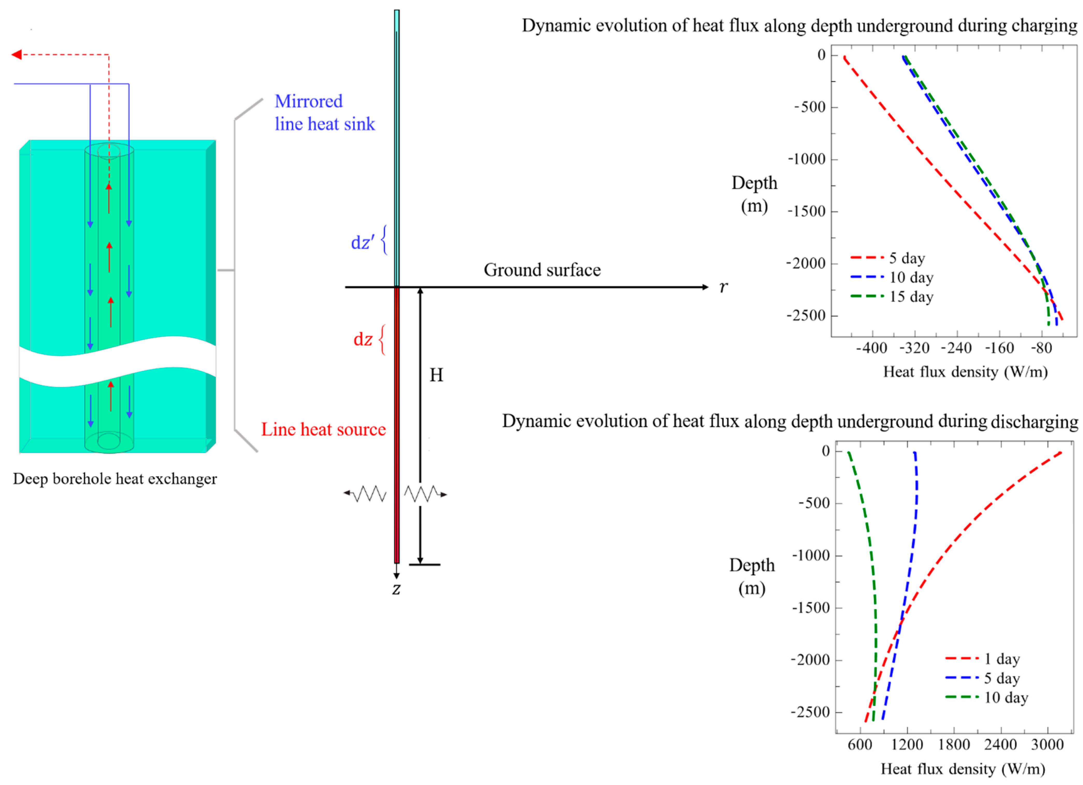
Heat flux density distribution along borehole depth:
q l ( z , τ ) = T f 1 ( z , τ ) T b ( z , τ ) R 11 = 1 R 12 2 + 4 R 11 R 12 e ( α + β ) z [ t o u t ( τ ) t i n ( τ ) + ( β + α ) m ˙ c p R 12 t o u t ( τ ) ] 1 R 12 2 + 4 R 11 R 12 e ( α β ) z [ t o u t ( τ ) t i n ( τ ) + ( α β ) m ˙ c p R 12 t o u t ( τ ) ] 1 R 12 2 + 4 R 11 R 12 [ ( β + α ) R 12 R 11 + 1 m ˙ c p R 11 ] 0 z T b ( z ξ , τ ) e ( α + β ) ξ d ξ + 1 R 12 2 + 4 R 11 R 12 [ ( α β ) R 12 R 11 + 1 m ˙ c p R 11 ] 0 z T b ( z ξ , τ ) e ( α β ) ξ d ξ T b ( z , τ ) R 11

2.3.3. Heat Extraction Model during Discharging

Similar to the thermal analysis of heat storage condition, when DBHE operates under the heat extraction condition for discharging, corresponding heat transfer could be modeled by the differential equations as following [29]:
{ m ˙ c p d T f 1 ( z ) d z = q 1 ( z ) = T f 1 ( z ) T b ( z ) R 11 + T f 1 ( z ) T f 2 ( z ) R 12 m ˙ c p d T f 2 ( z ) d z = q 2 ( z ) = T f 2 ( z ) T f 1 ( z ) R 12
Applying the Laplace transform to Equation (23), solutions to the temperature profile of circulating water along the two branches are:
T f 1 ( z , τ ) = 1 2 γ e ( α β ) z [ T f 2 ( 0 ) T f 1 ( 0 ) + ( β α ) m ˙ c p R 12 T f 1 ( 0 ) ] + 1 2 γ [ ( β α ) R 12 R 11 1 m ˙ c p R 11 ] 0 z T b ( z ξ , τ ) e ( α β ) ξ d ξ 1 2 γ e ( α + β ) z [ T f 2 ( 0 ) T f 1 ( 0 ) ( β + α ) m ˙ c p R 12 T f 1 ( 0 ) ] + 1 2 γ [ ( β + α ) R 12 R 11 + 1 m ˙ c p R 11 ] 0 z T b ( z ξ , τ ) e ( α + β ) ξ d ξ
T f 2 ( z , τ ) = 1 2 γ e ( α β ) z [ T f 2 ( 0 ) T f 1 ( 0 ) + ( β α ) m ˙ c p R 12 T f 2 ( 0 ) + R 12 R 11 T f 2 ( 0 ) ] 1 2 γ 1 m ˙ c p R 11 0 z T b ( z ξ , τ ) e ( α β ) ξ d ξ 1 2 γ e ( α + β ) z [ T f 2 ( 0 ) T f 1 ( 0 ) ( β + α ) m ˙ c p R 12 T f 2 ( 0 ) + R 12 R 11 T f 2 ( 0 ) ] + 1 2 γ 1 m ˙ c p R 11 0 z T b ( z ξ , τ ) e ( α + β ) ξ d ξ
Also, outlet temperature of the circulating water is obtained as:
t o u t ( τ ) = T f 2 ( 0 , τ ) = ( β α ) e β H + ( β + α ) e β H ( β α ) e β H + ( β + α ) e β H t i n ( τ ) + 2 α ( β α ) 0 H T b ( H ξ , τ ) e ( α β ) ξ d ξ + 2 α ( β + α ) 0 H T b ( H ξ , τ ) e ( α + β ) ξ d ξ ( β α ) e ( α + β ) H + ( β + α ) e ( α β ) H
And the heat flux density distribution along borehole depth is:
q l ( z , τ ) = T f 1 ( z , τ ) T b ( z , τ ) R 11 = 1 R 12 2 + 4 R 11 R 12 e ( α β ) z [ t o u t ( τ ) t i n ( τ ) + ( β α ) m ˙ c p R 12 t i n ( τ ) ] 1 R 12 2 + 4 R 11 R 12 e ( α + β ) z [ t o u t ( τ ) t i n ( τ ) ( β + α ) m ˙ c p R 12 t i n ( τ ) ] + 1 R 12 2 + 4 R 11 R 12 [ ( β α ) R 12 R 11 1 m ˙ c p R 11 ] 0 z T b ( z ξ , τ ) e ( α β ) ξ d ξ + 1 R 12 2 + 4 R 11 R 12 [ ( β + α ) R 12 R 11 + 1 m ˙ c p R 11 ] 0 z T b ( z ξ , τ ) e ( α + β ) ξ d ξ T b ( z , τ ) R 11

3. Heat Storage Performance Indicators

Deep BTES system could significantly increase the heat extraction output by releasing the heat stored in rock across seasons. Thus, an enhanced heat transfer potential during the heating season could be achieved. This section provides several indicators to evaluate its thermal performance.
As the operation proceeds, heat flow is continuously released into (charging stage) or extracted from (discharging stage) the rock zone. Therefore, heat exchange temperature difference between the circulating water and borehole wall keeps decreasing, which leads to gradual reduction of the heat exchange rate. Dynamic evolution of the thermal performance of deep BTES system during charging and discharging stages is illustrated in Figure 6. Integrating the instantaneous heat exchange rate throughout the heat storage or extraction stage, total heat exchange output Q s / e   between the circulating water and rock can be determined as follows.
Q s / e = τ c p m ˙ Δ T d τ
where Δ T is the temperature difference of supply and return water.
Additionally, heat flux density along borehole depth could be averaged to quantitatively characterize the heat exchange potential of deep BTES:
q s / e = Q s / e τ t o t H t o t
where, τ t o t is the total operation time and H t o t   denotes the total depth of the borehole.
In order to have a clear knowledge of heat transfer enhancement due to heat storage for deep BTES, heat storage efficiency could be defined as the ratio of total heat extraction during the heating season to total heat storage, which is calculated as:
η = Q e Q s
where, Q s   is the total heat storage amount and Q e is the total heat extraction output.

4. Evaluation

Thermal performance and heat transfer characteristics of the deep BTES system are investigated based on the DBHE implemented in a pilot demonstration project under operation studied by Zhao [12,26]. To validate the extended finite line heat source model (EFLS), OpenGeoSys (OGS) platform [41,42,43] is taken for cross check in the following sections. The OpenGeoSys is a scientific, open-source project for the development of numerical methods for the simulation of thermo-hydro-mechanical-chemical (THMC) processes in porous and fractured media. OGS applies finite element method for numerical simulation and implemented in C++. It is object-oriented with a focus on the numerical solution of coupled multi-field problems (multi-physics). Parallel versions of OGS are available relying on both MPI and OpenMP concepts. Application areas of OGS currently include water resources management, hydrology, geothermal energy, energy storage, CO2 sequestration, and waste deposition.

4.1. Project Overview

The pilot demonstration project of deep BTES for thermal performance analysis in this study is located in Qingdao, China [12,26]. According to the geothermal exploration data in Qingdao area summarized in Table 1, average geothermal temperature gradient of the borehole is 2.8 °C/100 m. Geological stratification of the conceptual model for the project shows that there are 5 rock layers underground in total. Since no fracture development was observed between each layer, thermo-physical parameters of rock vary minorly, which could be approximately regarded as homogenous distribution along depth. Anisotropic heat conductivities in each direction are presented in the fourth line. In this case, thermal property test shows that horizontal heat conductivities of λ s x and λ s y are the same, while vertical heat conductivity λ s z is relatively higher. The deep BTES system takes water as heat carrier, and its detailed design parameters are listed in Table 2.

4.2. Thermal Performance Analysis of Deep BTES during Heat Storage

This section centers on thermal performance of the deep BTES system under heat storage condition. In general, deep BTES shows distinctively different heat transfer characteristics depending on the charging temperature. Low temperature heat storage achieves heat transport from bottom to the top part of rock by circulating water, making the top section of rock warmer but the bottom section cooling down. This approach results in a more uniform distribution of borehole wall temperature. In contrast, high temperature heat storage releases heat into rock all the way along borehole depth, greatly increasing the temperature difference between circulating water and borehole wall. Thus, heat transfer throughout the full section was considerably enhanced. Comparison of low temperature and high temperature heat storage for the deep BTES system is depicted in Figure 7.

4.2.1. Thermal Performance of Deep BTES Charged by Low Temperature Water

Low temperature heat storage condition is simulated firstly to investigate the effect of heat transport from deep rock to the shallow layer. Inlet temperature of circulating water is set as 26 °C and the charging stage lasts for 30 days. The remaining operational parameters refer to Table 3.
Credibility of the EFLS model is validated against the numerical results carried out by the OGS software. Figure 8 compares simulation results based on the proposed model and reference OGS numerical solution for thermal performance of deep BTES during heat storage. It could be seen that the extended finite line heat source model (EFLS) prediction shows relatively larger difference initially against the numerical solution. Because refined grid resolution is required for the model to capture the rapid thermal response at the initial unsteady stage, thus small scale heat transfer details would be filtered out by the analytical solution in Equation (5). Heat storage gradually reaches the steady phase after 10 days of operation. Prediction errors of outflow temperature and heat storage rate are less than 0.5 °C and 20 kW, respectively. Good agreement between the two methods is achieved, thus demonstrating the excellent simulation credibility of the model.
Figure 9 depicts the simulated temperature profile of circulating water along depth of DBHE during the heat storage days. It can be clearly seen that temperature of the downward circulating water remains almost constant due to the good insulation of inner pipe. While circulating water temperature in the annulus is slightly overestimated by the EFLS model relative to the exact numerical solution. In addition, there is a temperature peak in the annular channel located at 750 m underground approximately. This observation is typical of the low temperature heat storage. Due to the fact that inlet temperature of the circulating water is within the rock temperature range at the top and bottom of the borehole, heat flux is continuously extracted by DBHE from the bottom section of rock while released into the top section. When the circulating water reaches bottom of the borehole from the insulated inner pipe, it would flow upward from bottom to the top in the annulus and extracts heat from the surrounding rock, leading to the temperature increase. Because temperature of the circulating water is relatively lower than the surrounding rock at the bottom section. Then, the circulating water turns to release the heat it carries into the rock and its temperature starts to decrease along the way as it continues to flow upward. Because the circulating water is sufficiently heated in the bottom section that its temperature is higher than the surrounding rock.
According to the geothermal temperature gradient underground (28 °C/km) and the peak temperature of the circulating fluid in the annulus, it is easy to estimate the location where the fluid temperature in the annulus transits from heat extraction to heat release. As shown in Figure 9, both the peak fluid temperature and the outlet temperature in the annulus channel decrease dynamically with operation time, ranging from 45.3 °C to 33.4 °C and 37 °C to 32.5 °C, respectively. So the temperature transition location varies within the depth range of 1082 m to 657 m during the heat storage.
Borehole wall temperature is described in Figure 10. As mentioned previously, due to the transient thermal response characteristics of DBHE, temperature profiles of borehole wall and circulating water given by the EFLS model differ somewhat from the exact numerical solution at the beginning of operation (1 to 10 days). Figure 10 shows that at 1 and 10 days of operation, EFLS model predicts a higher borehole temperature at the bottom section of DBHE than the exact solution. In view of the higher temperature difference between circulating water and the bottom borehole wall, heat flux extracted from the rock is higher correspondingly. Therefore, fluid temperature at the bottom of annulus channel rises faster. Whereas, borehole temperature at the top section is predicted relatively lower and more heat is released into rock, resulting in a faster temperature drop of the circulating water. In summary, it can be concluded that the EFLS model overestimates the borehole wall temperature and heat flux density along depth (especially within the heat extraction section at the bottom of DBHE) during the initial unsteady stage, but the simulation difference in outlet temperature is less than 1 °C. Furthermore, exact numerical solution of OGS shows that both the temperature of borehole wall and outlet flow decrease rapidly at the beginning of operation and quickly reach a relatively steady state, ending in a subtle decreasing trend. This is consistent with the thermal response characteristics of deep BTES in Section 2, and simulated by the EFLS model successfully.
Figure 11 shows distribution of the heat front along depth during the low temperature charging. Given the radial surplus temperature solution of rock determined by the EFLS model, location of the heat front could be truncated where the radial far-field rock temperature compares well with the initial rock temperature. It could be observed that the heat front is almost uniformly distributed at the initial stage. In fact, during the charging of deep BTES, the heat front propagates radially outward at a certain rate (this propagation rate is uniquely determined by the operation time and the thermal diffusion coefficient). Considering that thermo-physical parameters of rock are near uniform vertically according to Table 1, it is understandable that the heat front propagates as a uniform circle approximately over charging time. Moreover, it is also clear from Figure 11 that the thermally affected range narrows down near the depth of the circulating water in the annulus from 1082 m to 657 m underground (marked by circles). Because this region indicates a critical transition of the circulating water temperature, where the deep borehole heat exchanger switches from heat extraction to heat release into the rock. Therefore, the rock temperature field is less perturbed and forms a local buffer zone.
Simulation results of the rock temperature field underground can be referred to Figure 12. In order to validate the simulation accuracy of EFLS model for heat storage condition, comparison against the exact OGS numerical solution is carried out. Due to the fast thermal response at the beginning of operation, a noticeable temperature gradient could be observed near the borehole at 1 day. However, the thermally affected range is larger than that of the OGS numerical solution. In fact, the EFLS model tends to overestimate the thermal response outside the borehole initially, thus more heat is extracted or released into the rock, leading to a larger disturbed range. After the initial operation stage, simulation results for the rock temperature field are almost identical between the two methods, especially during the steady stage at 20 and 30 days. In addition, it is clear from Figure 12 that the heat front propagates dynamically during the heat storage, from 1 m at the initial stage all the way to 4 m at 30 days in the radial direction. Finally, it is worth noting that the exact OGS numerical solution also provides a detailed picture of the rock temperature field below the bottom of the borehole as a far-field boundary (see Figure 12a–d). It shows that rock temperature decrease below the borehole bottom is negligible which can be considered free of heat extraction basically. This observation proves that heat transfer in the radial direction is dominant compared to the vertical direction in the deep rock outside the borehole. Furthermore, heat front propagation at the top section of borehole is faster from 1 day to 10 days. Thermal response in the rock suggests that heat transfer of the low temperature circulating water could be enhanced to release more heat into the rock through flowing downward in the inner pipe and upward along the annulus.
Assuming there are 10 days of intermittence after heat storage, rock temperature field was simulated to investigate whether the heat extracted from the deep rock could be stored in the top section, as shown in Figure 13. Thermal recovery is rapid from 1 day to 7 days, and the rock temperature essentially stays steady after 7 days. In addition, the top section of rock recovered almost to its undisturbed thermal state after the initial fast heat diffusion. However, coldness accumulated at the bottom of borehole spreads out rather slowly after heat extraction, and the rock temperature still could not fully recover after 10 days. It requires longer time on account of the slow heat diffusion. This finding indicates that thermal state of rock due to the low temperature heat storage could only be maintained for a short period. Therefore, if the low temperature heat storage approach by transferring heat from bottom to the top section is adopted prior to heating season, intermittence should be necessarily avoided. On one hand, the heat extracted from deep rock to the surface will diffuse away quickly. On the other hand, it is difficult for deep rock to recover its original undisturbed temperature. In general, it is advisable to start heat extraction immediately after low temperature heat storage, otherwise this heat storage approach may not have much enhancement effect on heat transfer for the following heating season.

4.2.2. Thermal Performance of Deep BTES Charged by High Temperature Water

High temperature charging of deep BTES is featured with large heat exchange temperature difference, leading to intense heat transfer. Thermal performance of deep BTES evolves drastically throughout the operation, which is fundamentally different from the low temperature heat storage. Due to the strong local heat flux of DBHE released into the surrounding rock, simulation of deep BTES under high temperature charging condition poses a great challenge for robustness and stability of traditional numerical methods like finite element or finite difference. Additionally, numerical methods often require extremely refined spatiotemporal resolution to capture the rapid evolution of rock temperature field as well as details of transient heat transfer. Therefore, heat transfer simulation of this problem inevitably comes at high computational cost.
High temperature heat storage of the deep BTES system is based on constant inlet temperature at 100 °C. Simulation results are summarized in Figure 14. It shows that the outlet temperature was 71.6 °C after 5 days, 75.3 °C at 10 days, 78.96 °C at 15 days, then continued to rise to 81.66 °C at 20 days and 83.74 °C at 25 days until reaching 85.02 °C at 30 days. It is easy to find that the outlet temperature kept increasing with charging time. The increase rate was rapid in the early unsteady stage but gradually slowed down later, which was consistent with the heat transfer characteristics of DBHE. As the thermal performance of DBHE declined throughout the charging stage, heat exchange temperature difference between supply and return water gradually lowered from 18.4 °C at 5 days to 14.7 °C at 10 days, 11.04 °C at 15 days, and 8.34 °C at 20 days, 6.26 °C at 25 days until 4.98 °C at 30 days. Correspondingly, heat flux density along the borehole depth decreased dynamically with charging time as shown in Figure 14b. Moreover, it could also be observed that heat flux density decreased near linearly from top to bottom section along the borehole depth. This results from the fact that heat exchange temperature difference between the circulating water and surrounding rock decreased along the way, since rock temperature increased with the geothermal temperature gradient underground. The heat flux density dropped from 453.02 W/m at the topmost to 38.24 W/m at the bottom of borehole at 5 days, and 206.23 W/m to 55.63 W/m at 30 days. Heat flux density at the top of borehole decreased continuously throughout the charging stage. While at the bottom of borehole it kept increasing gradually from 38.24 W/m to 67.14 W/m during the initial charging period (5~15 days) and then began to decrease slowly from 58.14 W/m to 52.74 W/m at the end (20~30 days). Because circulating water temperature at the bottom of borehole rose faster during the initial charging period, then slowed down and rose slightly less than the surrounding rock at the steady stage (approximately at the same rate). Therefore, heat flux density at the bottom of borehole first increased, then decreased afterwards and remained constant at last. In addition, heat flux density rebounds at the bottom of borehole (approximately at depth of 2375 m to 2600 m) from 10 days to 30 days. The reason for this observation is that heat flux density is much higher at the top section of borehole and heats the surrounding rock faster, while it is smaller at the bottom, leading to slower thermal response of rock. Therefore, borehole wall at the bottom gradually reached steady thermal state with relatively small surplus temperature. When the circulating water in annulus flowed from bottom to the top of DBHE, it cooled down faster than the borehole wall, so heat exchange temperature difference decreased locally at the bottom of borehole, which accounts for the local rebound of heat flux density. Then as the circulating water continued to flow upward, its temperature gradually decreased with the borehole wall in parallel, leading to the linear distribution of heat flux density above the bottom section as shown in Figure 14b.
Evolution of rock temperature field underground during the high temperature charging is presented in Figure 15. High temperature gradient located in the vicinity of borehole. The heat front propagated in the radial direction rapidly from 0.5 m at 5 days to 2 m at 15 days, then remained stable afterwards. At the topmost part of borehole, temperature difference between circulating water and the surrounding rock could be up to 56 °C initially. Strong heat flux exists around the deep borehole, which requires local mesh refinement and demanding time step. In addition, simulation robustness is also greatly challenged. Thanks to the efficient and robust EFLS model, coarser grid resolution and larger time step for hours could be safely adopted to capture the transient heat transfer process, which does not lead to oscillation or failure for simulation of rock temperature especially in the vicinity of borehole with high gradient.

4.3. Thermal Performance of Deep BTES during the Discharging Stage after Heat Storage

Making full use of various heat sources for cross seasonal heat storage can significantly enhance the heat extraction potential of deep BTES during the discharging stage [13,14,17]. This section evaluates the enhanced heat transfer effect due to prior high temperature heat storage. Detailed operational parameters of the deep BTES system for heat extraction are shown in Table 4, where inlet temperature of the circulating water lowered sharply from 100 °C during the high temperature charging to 5 °C. Dynamic evolution of the temperature field outside borehole of DBHE is presented in Figure 16. Maximum temperature of the borehole wall after heat storage reaches 85 °C (at the topmost of borehole), and the temperature difference inside and outside of the borehole can be up to 80 °C. In face of so large temperature difference for heat extraction, much stronger heat flux occurs along the deep borehole, leading to more intense heat transfer and greater challenge for simulation.
Similar to the high temperature heat storage stage, the efficient EFLS model with coarser grid resolution still succeeded in depicting the dynamic rock temperature field during the discharging, which evolved even more drastically underground. After a dramatic evolution from 1 to 20 days and a transition stage from 30 to 60 days, the rock temperature field gradually reached a steady state. It is noteworthy that the rock temperature outside the borehole did not vary significantly which could be considered constant approximately from 70 to 120 days. Additionally, as could be seen from Figure 16, the heat front propagated fast at the initial period of heat extraction (1~20 days) and remained stable at around 5 m. Simulation results for the heat extraction performance parameters of the deep BTES system are shown in Figure 17. After high temperature heat storage, outlet temperature was 70.08 °C on the first day of discharging, which decreased to 53.80 °C at 5 days and continued decreasing to 40.44 °C at 10 days until to 26.38 °C at 20 days. The corresponding heat extraction temperature difference lowered from 65.08 °C to 21.38 °C. It was discovered that the outlet temperature decreased rapidly during the first 20 days of heat extraction. Specifically, average decreasing rate of heat extraction temperature difference was 2.2 °C/d. From 30 days on, heat transfer of the deep BTES system enters the transition stage and gradually stays steady state. Figure 17 indicates that the outlet temperature was 16.03 °C at 30 days, which dropped to 13.21 °C at 40 days and 12.26 °C at 50 days until 10.77 °C at 120 days. The heat transfer temperature differences were 11.03 °C, 8.21 °C, 7.26 °C and 5.77 °C respectively. In striking contrast to the initial rapid evolution, outlet temperature of deep BTES decreased rather slowly during the steady stage. Average decreasing rate of heat extraction temperature difference was 0.188 °C/d during 30~50 days, and it was even smaller at 0.021 °C/d from 50 days to 120 days. In terms of heat flux density distribution during the discharging, on the first day it decreased from 3145.58 W/m at topmost of the borehole to 665.78 W/m at the bottom. At 5 days, it was 1285.72 W/m~878.06 W/m, which continued decreasing to 444.7 W/m~762.8 W/m at 10 days, until 205.66 W/m~699.45 W/m at 20 days. Then from 30 days to 120 days, the heat flux density varied minorly, it was 39.9 W/m~393.53 W/m, 30.49 W/m~305.24 W/m, 29.21 W/m~267.33 W/m and 26.39 W/m~208.52 W/m respectively. Noticeably, the heat flux density decreased along depth from top to bottom of the deep borehole during the first day to 5 days. However, it turned to increase along depth after a short transition from 5 to 20 days. Because there existed large heat exchange temperature difference between the rock and the circulating water in the upper section of borehole during initial discharging. The circulating water got heated quickly along the way. Meanwhile, borehole temperature decreased faster especially in the upper section of borehole due to the strong heat flux extracted from rock. As a result, rock temperature drop in the upper section of borehole was larger than that at the bottom after a period of heat extraction. Consequently, during the subsequent heat extraction, the heat exchange temperature difference increased from topmost to the bottom of borehole at the same inlet temperature, resulting in the increase of heat flux density along depth.

4.4. Analysis on the Heat Storage Efficiency by Deep BTES

Figure 18 depicts the evolution of outlet water temperature and heat exchange rate of the deep BTES system during high temperature heat storage and subsequent heat extraction. High temperature heat storage by DBHE can only enhance the heat extraction potential during the heating season for 30 to 40 days in the initial stage of heating. Then it basically restored the original heat extraction state, which is characterized by transient and short heat transfer enhancement. For this project, maximum heat extraction output occurred at the first day of heating, where instantaneous heating rate could reach 3796.3 kW. While the heat extraction rate stabilized at 336.58 kW during the steady stage, thus maximum thermal performance enhancement up to 11.27 times was achieved due to seasonal heat storage. Throughout the discharging, outlet temperature of the circulating water was averaged at 30.16 °C, and the average heat extraction rate was 1467.7 kW with an enhancement ratio of 4.36 relative to the stable state. During the high temperature charging, maximum heat storage rate of 769.53 kW also fell on the first day, where the heat storage temperature difference was as high as 32.98 °C. Averaging the cumulative heat storage amount over the 30 days of charging, it yields an average heat storage rate of 512.46 kW with the average temperature difference of 21.97 °C. While the total heat storage amount was accumulated at 0.36 MWh. Given the total heat extraction which amounted to 4.23 MWh over the heating season, heat storage efficiency of the deep BTES system could be evaluated at 11.75.
Obviously, the heat storage efficiency calculated based on the total heat exchange amount is positively correlated with operation time (see Equations (28) and (30)). With respect to the deep BTES system in study, the heat storage stage was as short as 1 month, but the heating season lasted for 4 months, indicating that the ratio of discharging time to charging was 4:1. Therefore, heat storage efficiency by Equation (30) could not give reasonable evaluation since the discharging duration was not equivalent to charging. Although the heat storage stage was short, it has basically reached the steady state, which is not necessary to be extended. On the other hand, if the evaluation is on the basis of average heat exchange rate rather than the cumulative heat exchange amount, influence of the inconsistent heat storage or heat extraction duration can be properly avoided. Under this condition, thermal performance of the deep BTES system would be assessed more reasonably, where the heat storage efficiency was 2.86.
To grasp a clear knowledge of the thermal performance of deep BTES system under long-term operation, alternating charging and discharging was comprehensively simulated during the ten years cyclic operation. It shows in Figure 19 that very subtle decrease in the outlet temperature could be observed annually, which promises a great prospect in sustainable exploitation of deep geothermal energy through seasonal heat storage. It should be noted that in this case the charging time ratio is 1:1, i.e., both charging and discharging stage accounts for 6 months in the year. Influences of different charging time ratios, as well as charging and discharging temperature, circulating flow rates and optimal charging and discharging operation strategies on the thermal performance of deep BTES would be the future work.

5. Discussion

5.1. Comment on the EFLS Model for Deep BTES

EFLS model for heat transfer simulation of the deep BTES system during charging and discharging originates from the classical FLS model. However, traditional FLS model suffers from ideal assumption of uniform distributions of initial temperature and heat flux density along borehole depth, which ignores the geothermal gradient underground. Moreover, FLS model may not be able to precisely handle the complex geological conditions and anisotropic heat conduction effect in the deep subsurface, leading to oversimplification of the actual deep BTES and poor simulation accuracy. In efforts to relieve the shortcomings of FLS model to be applicable for simulation of deep BTES, an extended finite line source model is established. Tight coupling of the transient thermal response outside the borehole with quasi-steady state heat transfer inside the borehole was achieved. This model could be applied with great convenience to simulate the dynamic evolution of rock temperature as well as the heat flux density distribution and circulating flow temperature inside the borehole.
Despite of the merits, there are also several unsettled shortcomings for the EFLS model. First of all, the deep rock shows relatively weak anisotropic heat conductivity in this case. So strong anisotropic heat conductivity remains to be addressed to fully verify the EFLS model for simulation of anisotropic heat conduction. Secondly, the deep BTES system in study was only limited to a single DBHE scenario, while thermal performance of large scale DBHEs cluster is of great significance to be investigated. Additionally, in view of the complicated geological setting, groundwater would circulate around the deep borehole. Therefore, heat transfer with groundwater advection rather than pure heat condution in the rock outside borehole also deserves to be investigated for thermal performance evaluation of the deep BTES.

5.2. Discussion on Heat Storage by Deep BTES and Future Prospect

Although both the heat storage and heat extraction potential of DBHE have been greatly improved compared to shallow BHE, it still encounters certain bottleneck. Firstly, due to the pure heat conduction mechanism in rock, coldness or heat build-up near the borehole could not be evacuated in a timely manner. Even if high temperature heat storage was applied prior heating extraction, the heat extraction potential quickly deteriorated to a low level after the strong heat impulses were released during the initial discharging stage. In general, thermal performance of the deep BTES system during discharging features limited and short-term enhancement, making it impossible to sustain long-term efficient operation.
Secondly, there exists great gap between the energy production on the ground side and building demand side. As shown in Figure 17, initial heating supply capacity of the deep BTES after heat storage was rather high, which exceeded the building demand. In the future, simulation of the overall building energy system by integration with the building terminal is in urgent need to be addressed, which contributes to real-time match between the demand side and the energy production side.

6. Conclusions

Development of efficient simulator could provide valuable insight into the design and operation strategies of deep BTES, which is essential for overall understanding of this promising technology. To this end, this paper focuses on the general framework for heat transfer modeling and thermal performance analysis of the deep BTES. A generic EFLS (extended finite line source) model is proposed to perform comprehensive simulation for deep BTES. It allows for efficient, but detailed consideration of the anisotropic heat conduction of deep rock and spatio-temporal distribution of heat flux density along depth of the deep borehole. Key indicators for thermal performance of deep BTES during the charging and discharging stages are simulated, including the heat flux density distribution along depth, heat front propagation, outlet temperature and real-time heat storage or extraction rate. The main findings of this paper can be summarized in the following:
(1)
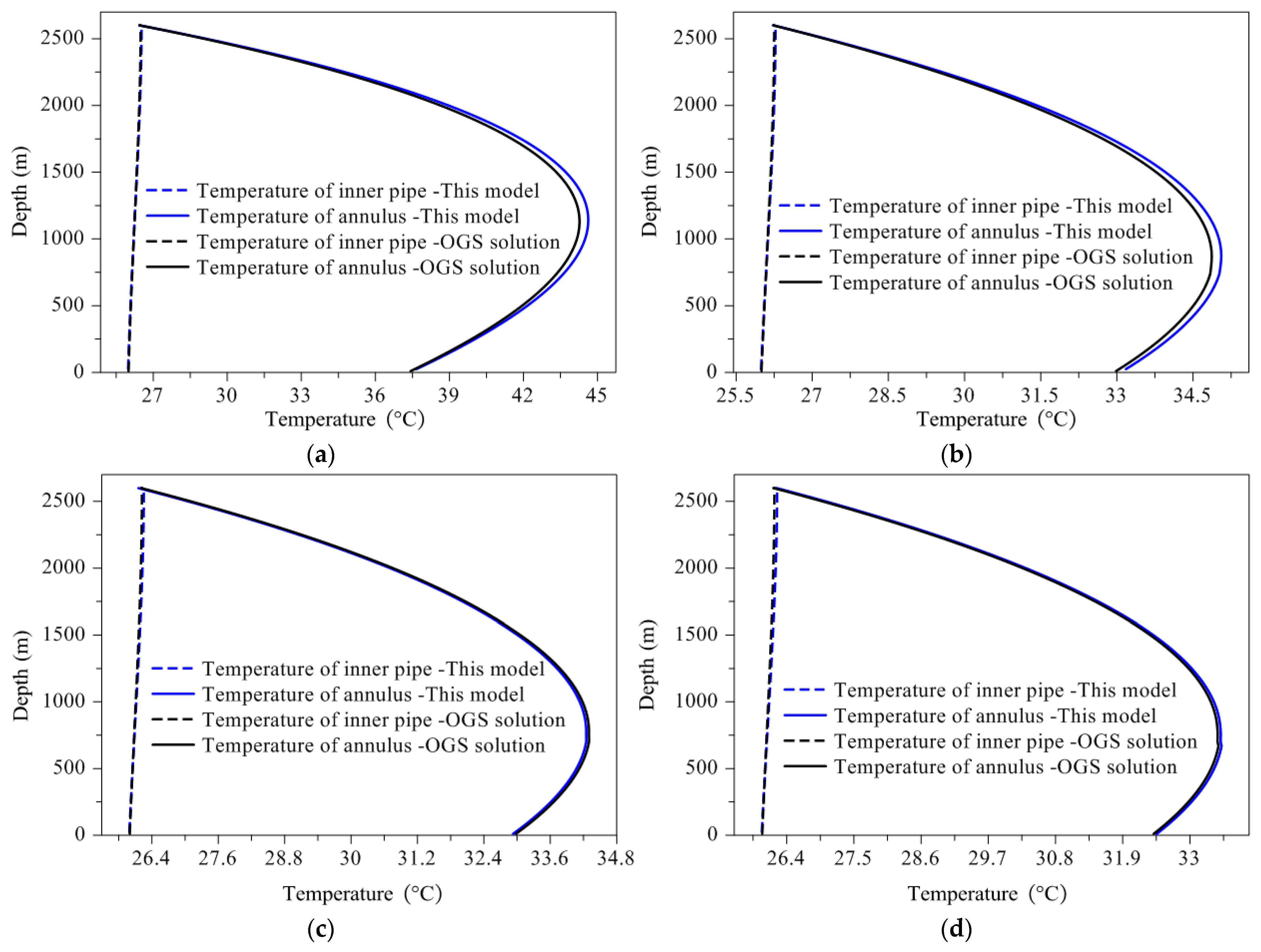
EFLS model proves robust and efficient enough for credible simulation of actual deep BTES system. In addition, the model allows flexible switch between multiple operation conditions (operating or intermittence, heat extraction or heat storage, constant or variable flow rate and inlet temperature), which greatly facilitates the simulation of complicated heat transfer in deep BTES system.
(2)
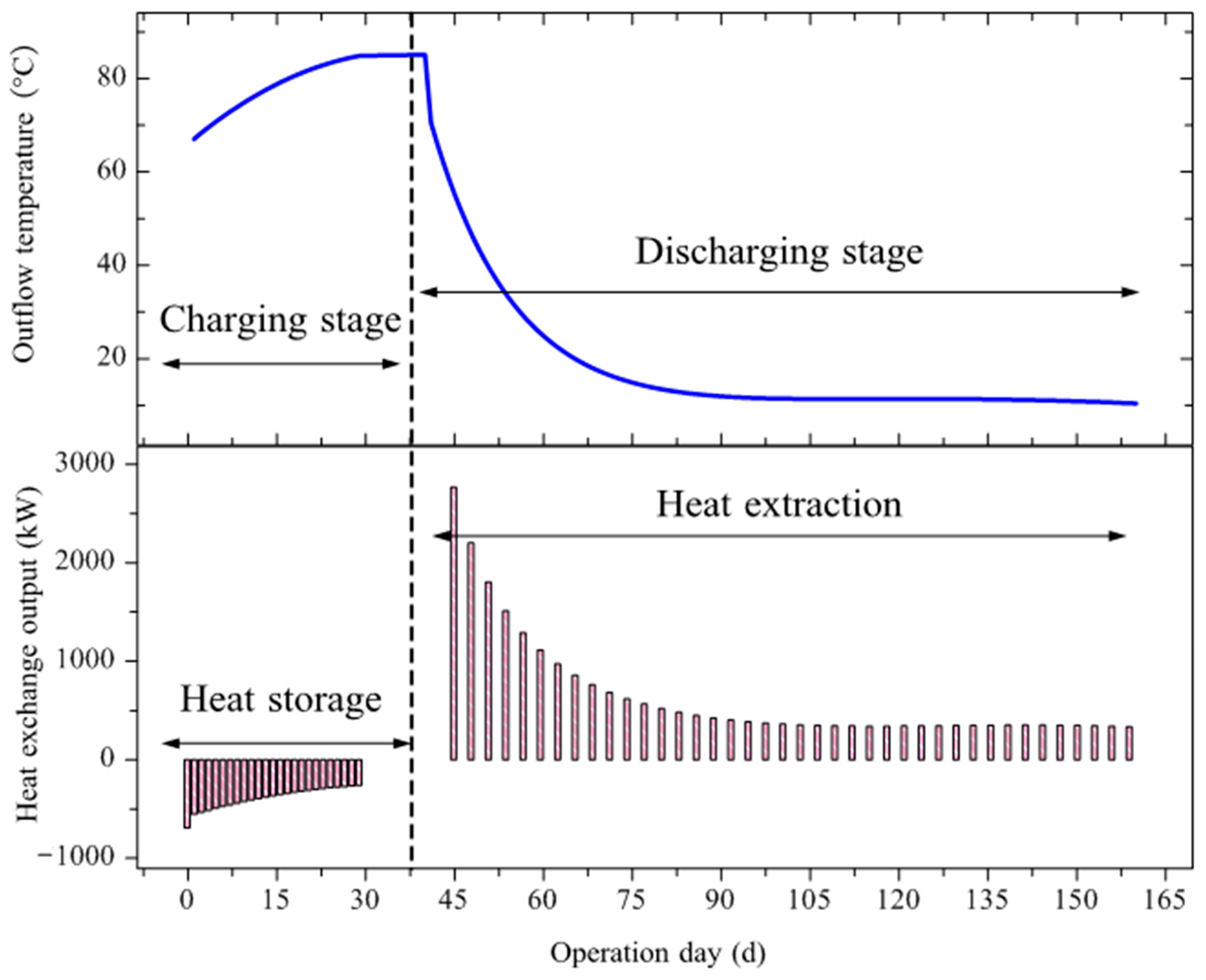
Deep BTES transits rapidly from the initial unsteady heat transfer to the steady stage. The entire operation can be divided into three typical phases: initial unsteady phase, transition phase and the terminal steady phase. In the initial start-up phase, outlet temperature and the heat storage or heat extraction rate displays a rapid decrease. Shortly after the transition, the deep BTES enters the steady heat transfer state. Afterwards, it began operating steadily with only negligible fluctuation in the thermal performance parameters.
(3)
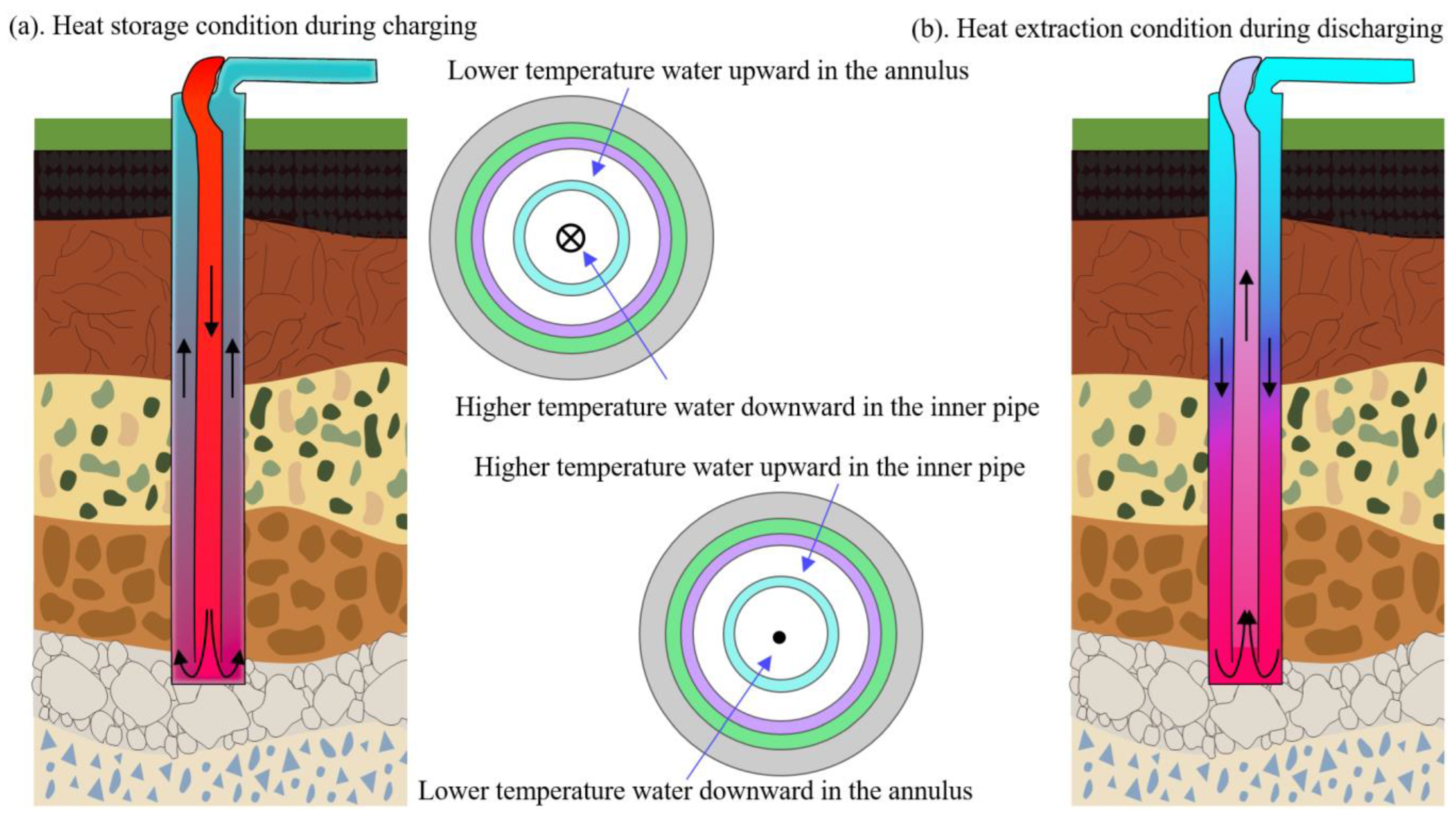
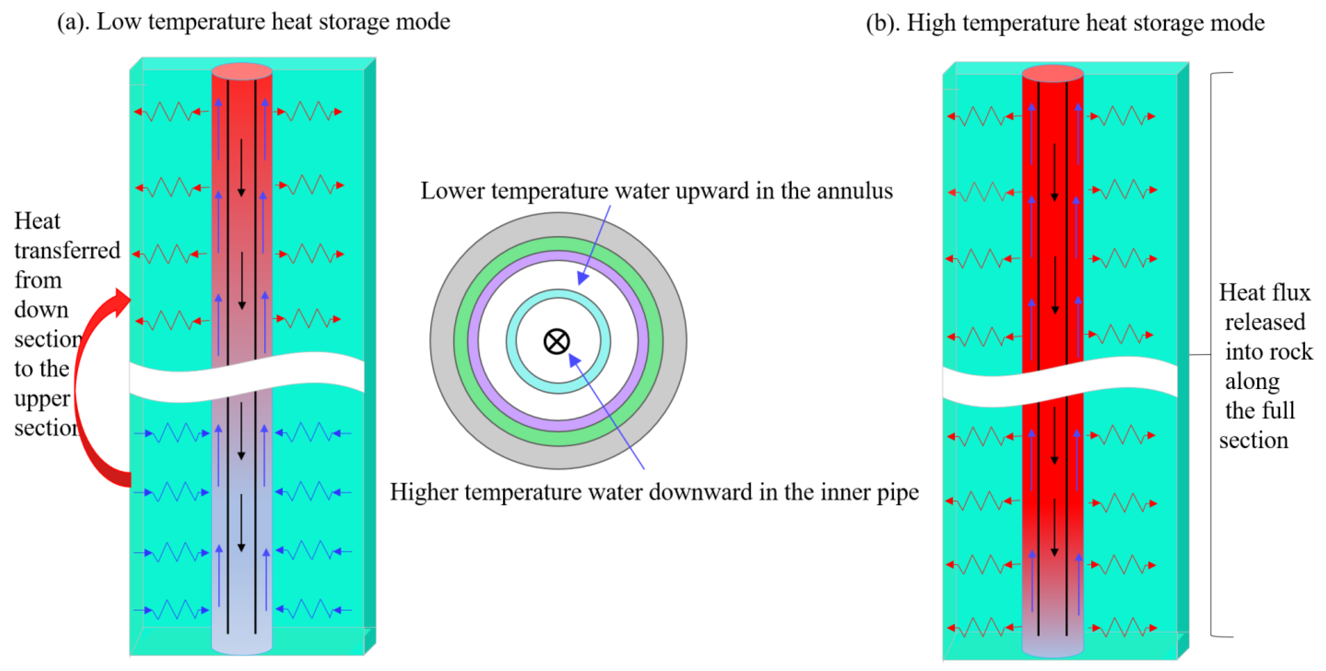
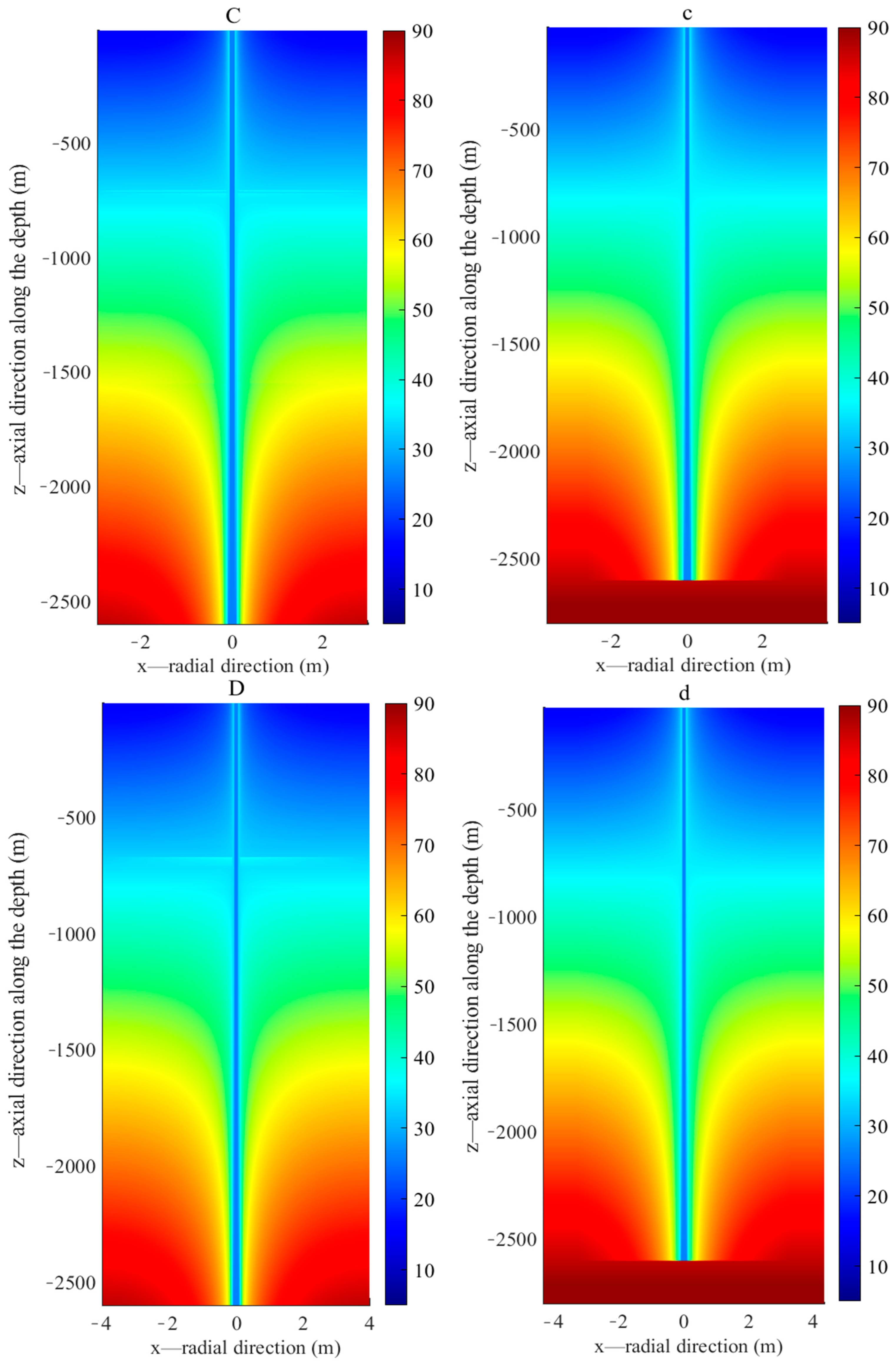
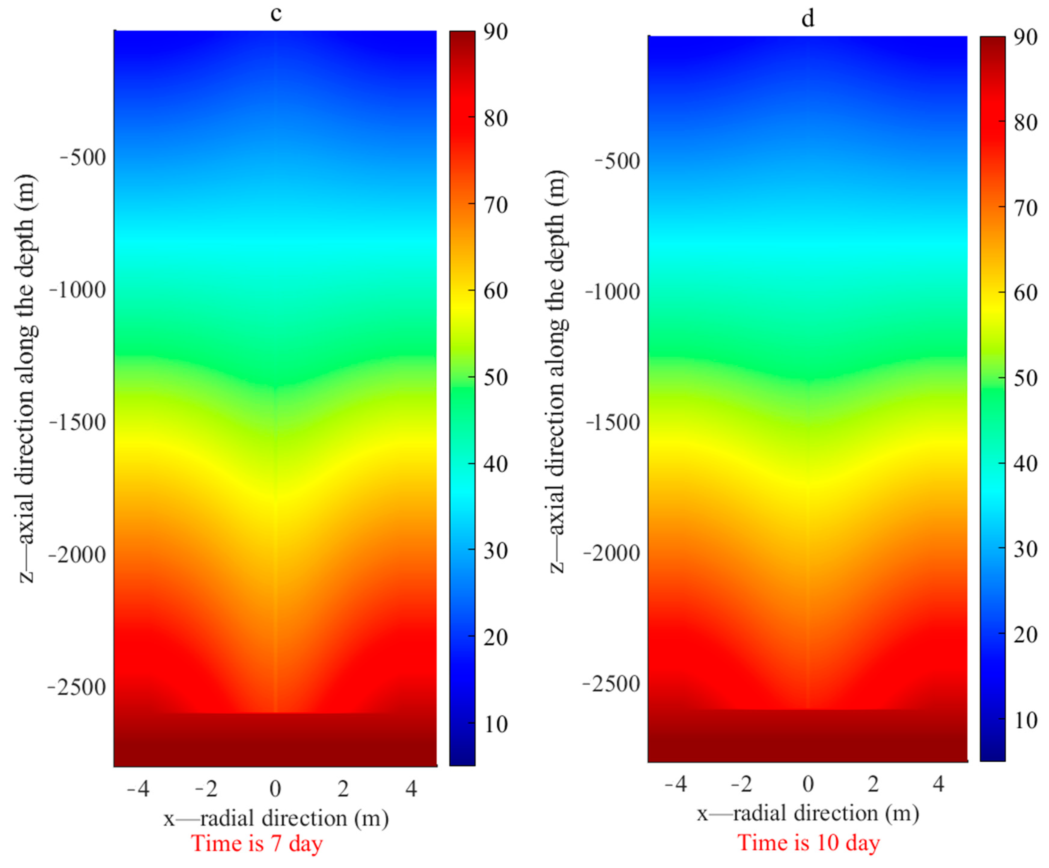
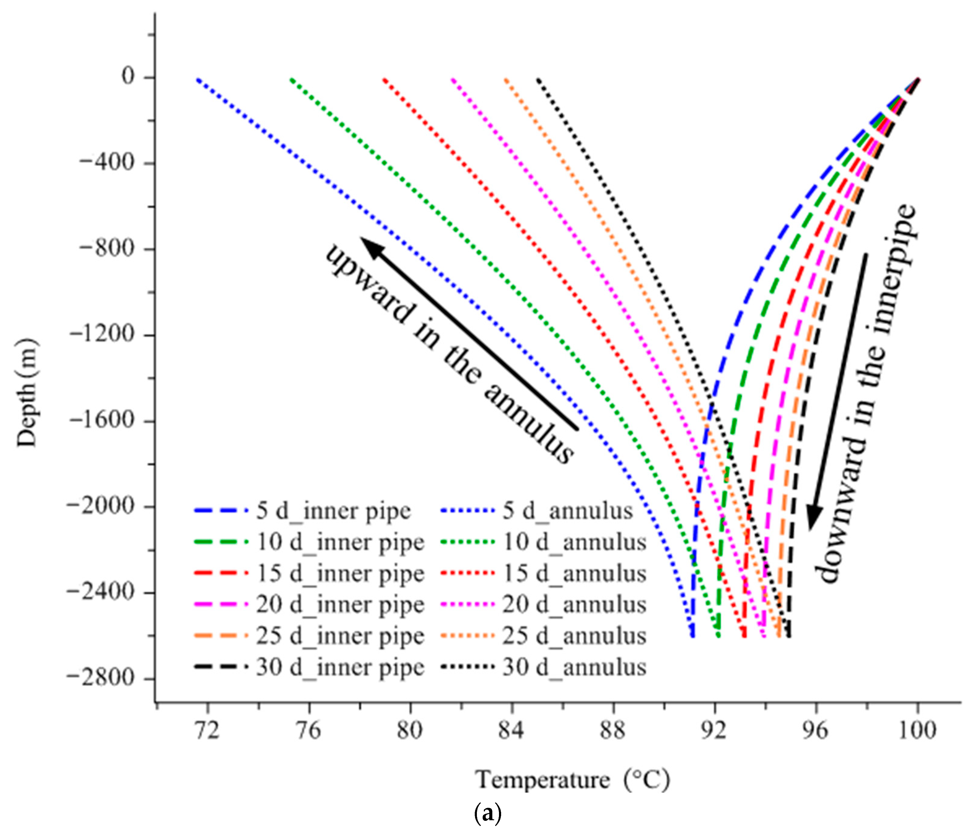
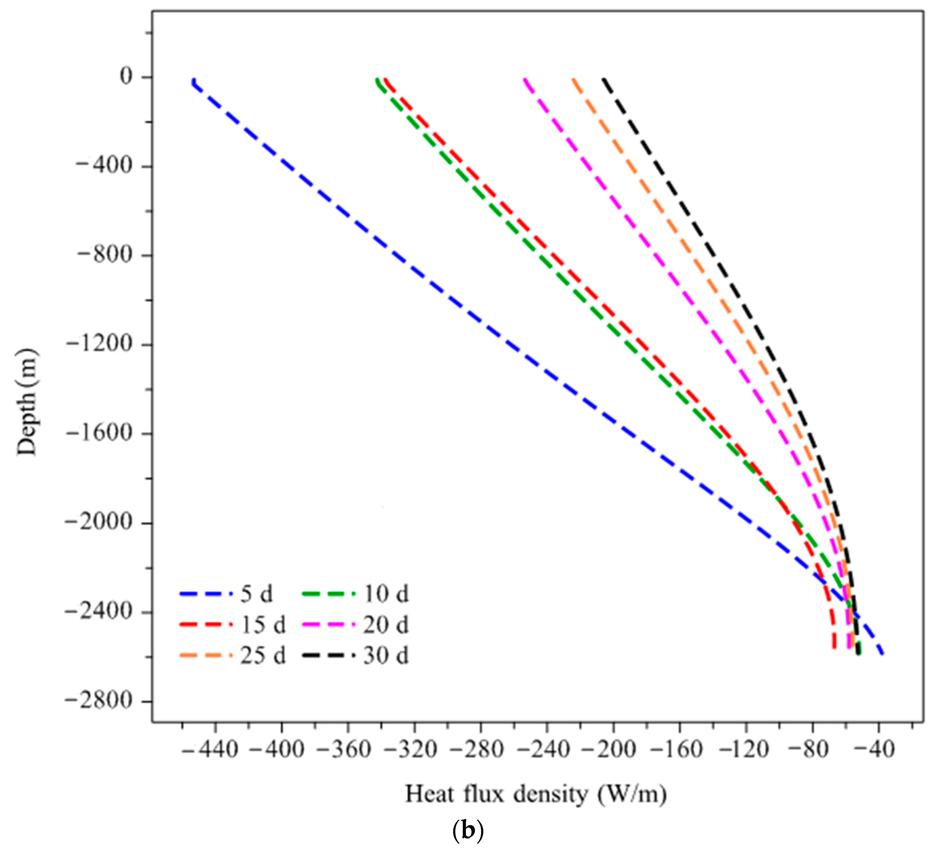
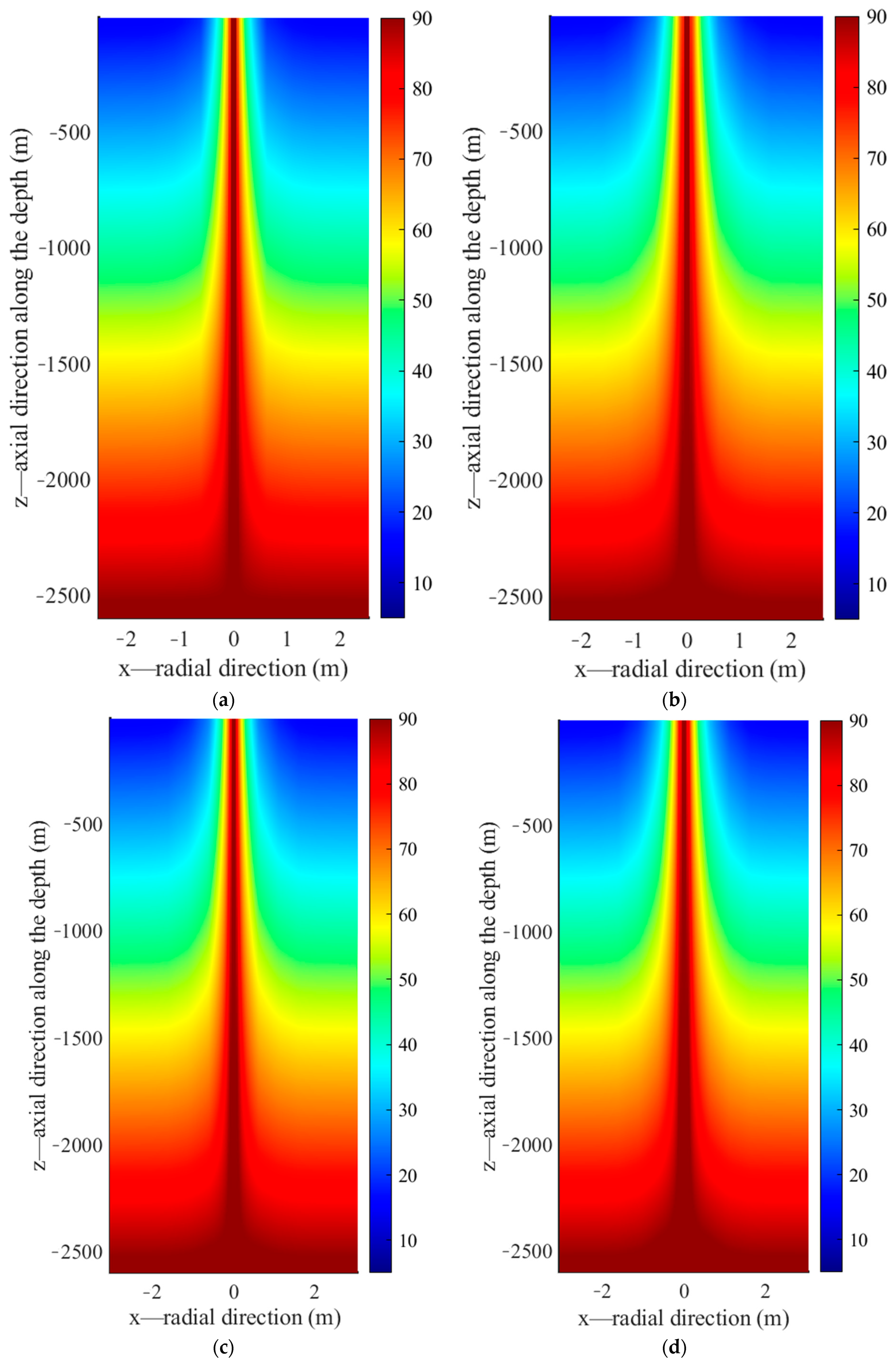
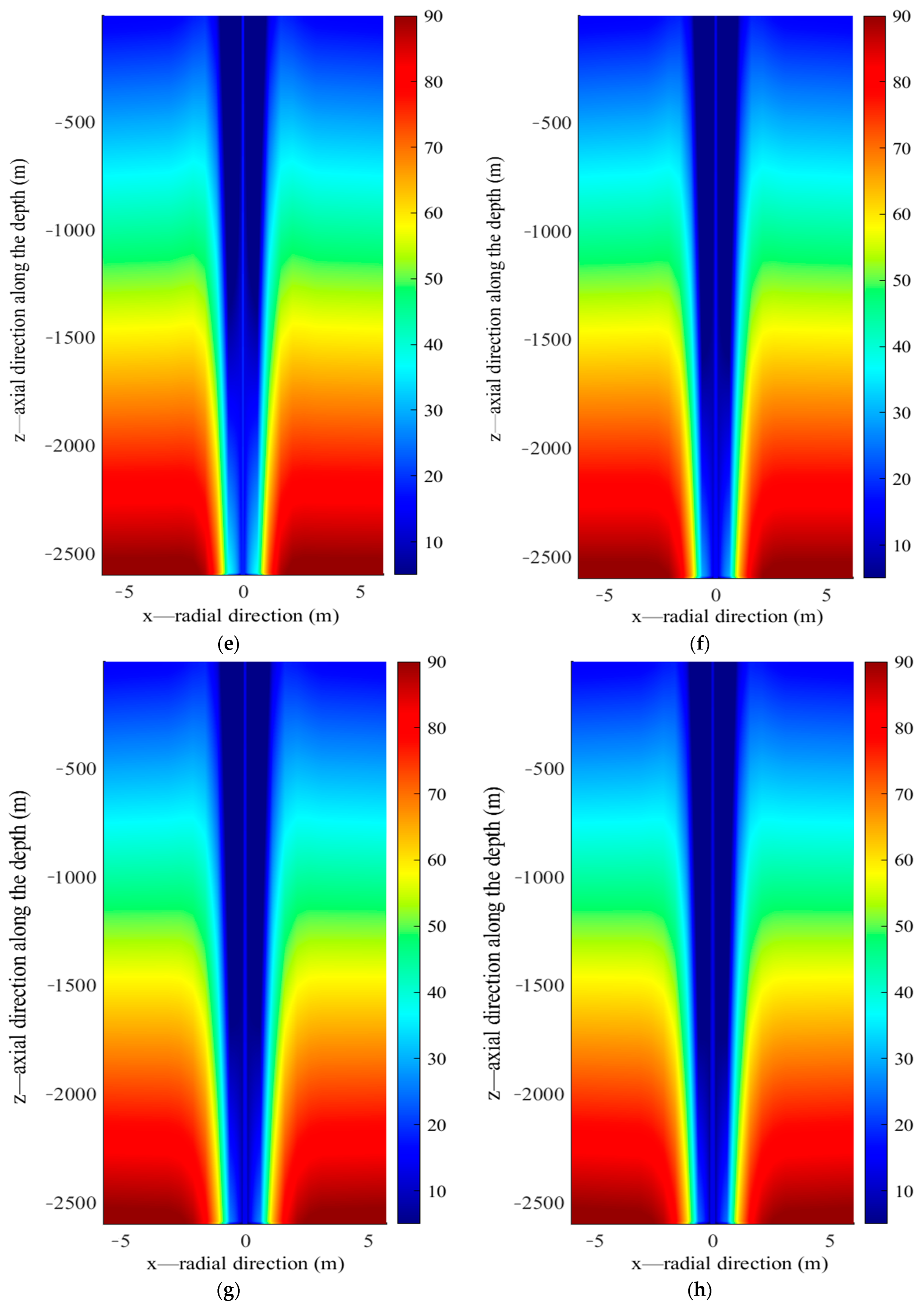
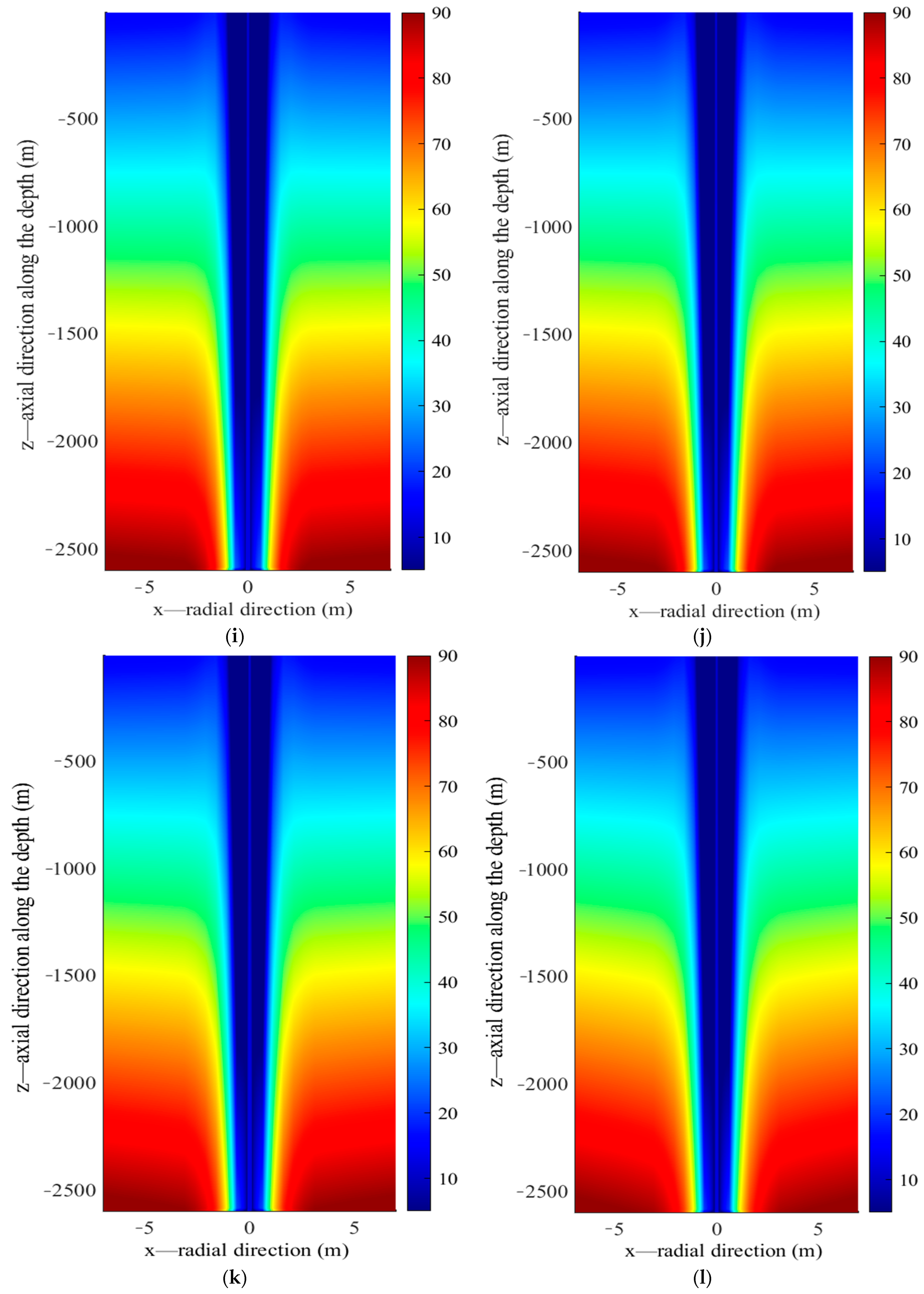
During the low temperature heat storage, only upper section of the borehole wall acts as effective heat storage section while heat extraction occurs along the bottom part. Circulating water in the inner pipe reaches its maximum temperature at the bottom of the borehole and returning upward to the surface along the annulus. Given the relatively uniform distribution of rock thermal parameters along depth, heat front spreads along the radial direction at almost the same rate, resulting in a thermal affected zone of the same size vertically. V-shaped isotherm profile in the rock could be clearly observed during the charging. In addition, greater temperature decrease occurs at the bottom of the borehole than the top section due to the linear increase of heat flux density along depth.
(4)
Low temperature heat storage displays distinctive characteristics from high temperature heat storage. When low temperature heat storage is carried out by transferring heat from the deeper rock to the shallower layers, enhancement of heat extraction potential during the heating season is not significant. This could be justified from two aspects. On one hand, the heat extracted from deep rock to the surface will diffuse away quickly. On the other hand, it is difficult for deep rock to recover its original undisturbed temperature. In general, it is advisable to start heat extraction immediately after low temperature heat storage.
(5)
High temperature heat storage by DBHE can only enhance the heat extraction potential for 30 to 40 days in the initial stage of heating. Maximum thermal performance enhancement up to 11.27 times was achieved due to seasonal heat storage. Throughout the discharging, average heat extraction rate was 1467.7 kW with an enhancement ratio of 4.36 relative to the stable state. Moreover, to properly eliminate influence of the inconsistent heat storage or heat extraction duration, evaluation of heat storage efficiency could be performed based on average heat exchange rate. Under this condition, thermal performance of the deep BTES system would be assessed more reasonably, where the heat storage efficiency was 2.86.
As is known, thermal performance of deep BTES is sensitive to many geological and operational parameters, also the downstream heating system. The core parameters of deep BTES system remain to be fully analyzed under different operating conditions, including circulating flow rate, inlet temperature, drilling depth, borehole radius, thermal conductivity of rock and annulus pipe, geothermal gradient, and intermittence strategy. On the other hand, this study only focuses on seasonal heat storage of a single DBHE, whereas thermal performance of the DBHE cluster integrating a variety of heat storage sources is necessary to be investigated. Moreover, future work should aim at transient simulation of the overall deep BTES heating system including the above ground facilities as well as in-situ field test data collected from the pilot demonstration project. Last but not the least, heat storage or heat extraction strategy to optimize the operation of deep BTES is also of great significance, which could help to push this promising technology to economic viability.

Author Contributions

All authors contributed to the study conception and design. Material preparation, data collection and analysis were performed by Y.Z., C.D. and D.X. The first draft of the manuscript was written by X.Q. The project administration and funding acquisition was carried out by Y.Z. and J.W. All authors commented on previous versions of the manuscript. All authors have read and agreed to the published version of the manuscript.

Funding

This research received no external funding.

Data Availability Statement

The data presented in this study are available in this article.

Acknowledgments

The authors gratefully acknowledge the support of College of Energy of Zhejiang university.

Conflicts of Interest

The authors declare no conflict of interest. The funders had no role in the design of the study; in the collection, analyses, or interpretation of data; in the writing of the manuscript, or in the decision to publish the results.

Nomenclature

Nomenclature for the abbreviations and notations concerned in the paper are listed below:
Nomenclature
BHEBorehole heat exchanger
DBHEDeep borehole heat exchanger
GSHPBorehole thermal energy storage
BTESBorehole thermal energy storage
FLSFinite line source model
EFLSExtended finite line source model
OGSOpen GeoSys
Notations
z Depth of borehole
τ Operation time of deep borehole heat exchanger
a s Thermal diffusion coefficient
r b Radius of borehole
H Drilling depth of borehole
T i n i t Initial rock temperature distribution
T s Rock temperature field
m ˙ Circulating flow rate
t i n Inlet temperature of circulating water
t o u t Outlet temperature of circulating water
T f 1 Flow temperature distribution along annulus of deep borehole heat exchanger
T f 2 Flow temperature distribution along inner pipe of deep borehole heat exchanger
Q s 
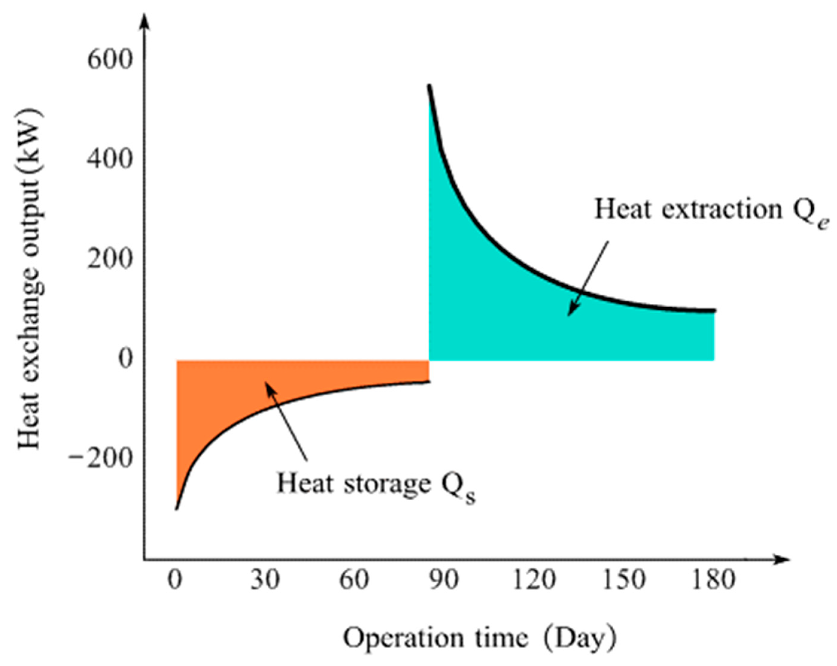
Total heat storage amount during charging of deep borehole heat exchanger
Q e Total heat extraction output during discharging of deep borehole heat exchanger

References

  1. Thomas, K.; Renzo, B.; Walter, E. System performance of a deep borehole heat exchanger. Geothermics 2002, 31, 687–708. [Google Scholar]
  2. Rybach, L.; Hopkirk, R. Shallow and deep borehole heat exchangers-achievements and prospects. In Proceedings of the 1st World Geothermal Congress (WGC1995), Florence, Italy, 18–31 May 1995; pp. 2133–2139. [Google Scholar]
  3. Deng, J.W.; Wei, Q.P.; Liang, M.; He, S.; Zhang, H. Field test on energy performance of medium-depth geothermal heat pump systems (MD-GHPs). Energy Build. 2019, 184, 289–299. [Google Scholar] [CrossRef]
  4. Bu, X.B.; Ran, Y.M.; Zhang, D.D. Experimental and simulation studies of geothermal single well for building heating. Renew. Energy 2019, 143, 1902–1909. [Google Scholar] [CrossRef]
  5. Cai, W.L.; Wang, F.H.; Chen, S.; Shao, H.B. Analysis of heat extraction performance and long-term sustainability for multiple deep borehole heat exchanger array: A project-based study. Appl. Energy 2021, 289, 116590. [Google Scholar] [CrossRef]
  6. Huang, Y.; Zhang, Y.; Xie, Y.; Zhang, Y.; Ma, J. Field test and numerical investigation on deep coaxial borehole heat exchanger based on distributed optical fiber temperature sensor. Energy 2020, 210, 118643. [Google Scholar] [CrossRef]
  7. Wang, Z.H.; Wang, F.H.; Liu, J.; Ma, Z.J.; Han, E.S.; Song, M.J. Field test and numerical investigation on the heat transfer characteristics and optimal design of the heat exchangers of a deep borehole ground source heat pump system. Energy Convers. Manag. 2017, 153, 603–615. [Google Scholar] [CrossRef]
  8. Schulte, D. Simulation and Optimization of Medium Deep Borehole Thermal Energy Storage Systems. Ph.D. Thesis, Technische Universitat Darmstadt, Darmstadt, Germany, 2016. [Google Scholar]
  9. Luo, Y.Q.; Guo, H.S.; Meggers, F.; Zhang, L. Deep coaxial borehole heat exchanger: Analytical modeling and thermal analysis. Energy 2019, 185, 1298–1313. [Google Scholar] [CrossRef]
  10. Ma, L.; Zhao, Y.Z.; Yin, H.M.; Zhao, J.; Li, W.J.; Wang, H.Y. A coupled heat transfer model of medium-depth downhole coaxial heat exchanger based on the piecewise analytical solution. Energy Convers. Manag. 2019, 204, 112038. [Google Scholar] [CrossRef]
  11. Liu, J.; Wang, F.H.; Cai, W.L.; Wang, Z.H.; Wei, Q.P.; Deng, J.W. Numerical study on the effects of design parameters on the heat transfer performance of coaxial deep borehole heat exchanger. Int. J. Energy Res. 2019, 43, 6337–6352. [Google Scholar] [CrossRef]
  12. Zhao, Y.Z.; Pang, Z.H.; Huang, Y.H.; Ma, Z.B. An efficient hybrid model for thermal analysis of deep borehole heat exchangers. Geotherm. Energy 2020, 8, 18. [Google Scholar] [CrossRef]
  13. Jordi, J.M. Large-Scale Underground Thermal Energy Storage Using Industrial Waste Heat to Supply District Heating. Bachelor’s Thesis, Universitat de Lleida, Lleida, Spain, 2014. [Google Scholar]
  14. Emil, N.; Patrik, R. Performance evaluation of an industrial borehole thermal energy storage (BTES) project-Experiences from the first seven years of operation. Renew. Energy. 2019, 143, 1022–1034. [Google Scholar]
  15. Xu, L.Y.; Torrens, I.; Guo, F.; Yang, X.D.; Hensen, J.L.M. Application of large underground seasonal thermal energy storage in district heating system: A model-based energy performance assessment of a pilot system in Chifeng, China. Appl. Therm. Eng. 2018, 137, 319–328. [Google Scholar] [CrossRef]
  16. Xiong, R.; Li, H.L.; Zhou, X. Advanced energy storage technologies and their applications. Energies 2017, 10, 1366. [Google Scholar] [CrossRef] [Green Version]
  17. Diersch, H.J.G.; Bauer, D. Analysis, modeling and simulation of underground thermal energy storage (UTES) systems. In Woodhead Publishing Series in Energy, Advances in Thermal Energy Storage Systems; Woodhead Publishing: Sawston, UK, 2015; pp. 149–183. [Google Scholar]
  18. Michael, L.; Paulo, C.T.V. Seasonal thermal energy storage: A critical review on BTES systems, modeling, and system design for higher system efficiency. Energies 2017, 10, 743–766. [Google Scholar]
  19. Bastian, W.; Wolfram, R.; Schulte, D.; Kristian, B.; Ingo, S. Characteristics of medium deep borehole thermal energy storage. Int. J. Energy Res. 2016, 40, 1855–1868. [Google Scholar]
  20. Kristian, B.; Wolfram, R.; Bastian, W.; Schulte, D.; Sebastian, H.; Ingo, S. Seasonal high temperature heat storage with medium deep borehole heat exchangers. Energy Procedia 2015, 76, 351–360. [Google Scholar]
  21. Farzin, M.R.; Alan, S.F. Solar community heating and cooling system with borehole thermal energy storage—Review of systems. Renew. Sustain. Energy Rev. 2016, 60, 1550–1561. [Google Scholar]
  22. Fang, L.; Diao, N.R.; Shao, Z.K.; Zhu, K.; Fang, Z.H. A computationally efficient numerical model for heat transfer simulation of deep borehole heat exchangers. Energy Build. 2018, 167, 79–88. [Google Scholar] [CrossRef]
  23. Georgios, F.; Soteris, K. Ground heat exchangers-A review of systems, models and applications. Renew. Energy 2007, 32, 2461–2478. [Google Scholar]
  24. Li, M.; Zhu, K.; Fang, Z.H. Analytical methods for analysis of vertical ground heat exchangers (GHEs). In Advances in Ground Heat Pump Systems; Simon, R., Ed.; Woodhead Publishing: Sawston, UK; Elsevier Inc.: Amsterdam, The Netherlands, 2016. [Google Scholar]
  25. Bauer, D.; Heidemann, W.; Diersch, H.J.G. Transient 3D analysis of borehole heat exchanger modeling. Geothermics 2011, 40, 250–260. [Google Scholar] [CrossRef]
  26. Zhao, Y.; Qin, X.; Shi, X. Heat transfer modeling on high-temperature charging and discharging of deep borehole heat exchanger with transient strong heat flux. Sustainability 2022, 14, 9702. [Google Scholar] [CrossRef]
  27. Luo, Y.Q.; Yu, J.H.; Yan, T.; Zhang, L.; Liu, X. Improved analytical modeling and system performance evaluation of deep coaxial borehole heat exchanger with segmented finite cylinder source method. Energy Build. 2020, 212, 109829. [Google Scholar] [CrossRef]
  28. Luo, Y.Q.; Cheng, N.; Xu, G.Z. Analytical modeling and thermal analysis of deep coaxial borehole heat exchanger with stratified-seepage-segmented finite line source method (S3-FLS). Energy Build. 2021, 257, 111795. [Google Scholar] [CrossRef]
  29. Hellstrom, G. Ground Heat Storage Thermal Analysis of Duct Storage Systems. Ph.D. Thesis, University of Lund, Lund, Sweden, 1991. [Google Scholar]
  30. Eskilson, P. Thermal Analysis of Heat Extraction Boreholes. Ph.D. Thesis, University of Lund, Lund, Sweden, 1987. [Google Scholar]
  31. Carslaw, H.S.; Jaeger, J.C. Conduction of Heat in Solids; Claremore Press: Oxford, UK, 1947; pp. 257–265. [Google Scholar]
  32. Zeng, H.; Diao, N.; Fang, Z.H. A finite line-source model for boreholes in geothermal heat exchangers. Heat Transfer Asian Res. 2002, 31, 558–567. [Google Scholar] [CrossRef]
  33. Jaime, A.R.; Philipp, B.; Peter, B. Influence of spatially variable ground heat flux on closed-loop geothermal systems: Line source model with nonhomogeneous Cauchy-type top boundary conditions. Appl. Energy 2016, 180, 572–585. [Google Scholar]
  34. Jaime, A.R.; Philipp, B.; Peter, B. A finite line source model with Cauchy-type top boundary conditions for simulating near surface effects on borehole heat exchangers. Energy 2016, 98, 50–63. [Google Scholar]
  35. Tatyana, V.B.; Álvaro, M.; Esther, F.; Juan, L.G.S.; José, M.I.; Jezabel, P.; Pedro, J.F.d.C.; Javier, F.U. Finite line-source model for borehole heat exchangers: Effect of vertical temperature variations. Geothermics 2009, 38, 263–270. [Google Scholar]
  36. Li, M.; Lai, A.C.K. Heat-source solutions to heat conduction in anisotropic media with application to pile and borehole ground heat exchangers. Appl. Energy 2012, 96, 451–458. [Google Scholar] [CrossRef]
  37. Zhang, L.; Zhang, Q.; Huang, G. A transient quasi-3D entire time scale line source model for the fluid and ground temperature prediction of vertical ground heat exchangers (GHEs). Appl. Energy 2016, 170, 65–75. [Google Scholar] [CrossRef]
  38. Massimo, C. Fluid and borehole wall temperature profiles in vertical geothermal boreholes with multiple U-tubes. Renew. Energy 2016, 96, 137–147. [Google Scholar]
  39. Bauer, D.; Heidemann, W.; Müller-Steinhagen, H.; Diersch, H.J.G. Thermal resistance and capacity models for borehole heat exchangers. Int. J. Energy Res. 2011, 35, 312–320. [Google Scholar] [CrossRef]
  40. Michele, D.C.; Massimo, T.; Angelo, Z.; Roberto, Z. A computational capacity resistance model (CaRM) for vertical ground-coupled heat exchangers. Renew. Energy 2010, 35, 1537–1550. [Google Scholar]
  41. Kolditz, O.; Bauer, S.; Bilke, L. OpenGeoSys: An open-source initiative for numerical simulation of thermo-hydro-mechanical/chemical (THM/C) processes in porous media. Environ. Earth Sci. 2012, 67, 589–599. [Google Scholar] [CrossRef]
  42. Georg, K.; Norihiro, W. OpenGeoSys-Gem: A numerical tool for calculating geochemical and porosity changes in saturated and partially saturated media. Phys. Chem. Earth 2014, 70, 138–149. [Google Scholar]
  43. Bastian, J.G.; Dedong, L.; Sebastian, B. The coupled simulator ECLIPSE—OpenGeoSys for the simulation of CO2 storage in saline formations. Energy Procedia 2011, 4, 3794–3800. [Google Scholar]
Figure 1. Schematic for charging and discharging of the deep BTES system.
Energies 15 08366 g001
Figure 2. Schematic for spatio-temporal distribution of heat flux density along borehole depth of the deep borehole heat exchanger.
Energies 15 08366 g002
Figure 3. Transient evolution of heat flux during charging and discharging of the deep BTES system.
Energies 15 08366 g003
Figure 4. Two typical operating conditions for heat storage and heat extraction of the deep BTES system.
Energies 15 08366 g004
Figure 5. Schematic for cross section of coaxial annular borehole heat exchanger and corresponding thermal circuit.
Energies 15 08366 g005
Figure 6. Schematic of heat exchange output during the charging and discharging stage of deep BTES.
Energies 15 08366 g006
Figure 7. Comparison of low temperature and high temperature heat storage for the deep BTES system.
Energies 15 08366 g007
Figure 8. Evolution of heat storage rate and outlet temperature during the low temperature heat storage days.
Energies 15 08366 g008
Figure 9. Comparison of simulation results of circulating fluid temperature profiles along depth in the annulus and inner column of DBHE during the low temperature heat storage days (a)—1 day, (b)—10 day, (c)—20 day, (d)—30 day.
Energies 15 08366 g009
Figure 10. Distribution of borehole temperature along depth during the low temperature heat storage days.
Energies 15 08366 g010
Figure 11. Heat front propagation and radial far field rock temperature (near the boundary of radial heat front) along depth during the low temperature heat storage days (a)—1 day, (b)—10 day, (c)—20 day, (d)—30 day.
Energies 15 08366 g011
Figure 12. Rock temperature distribution underground during the low temperature heat storage days ((AD) depict the simulation results at 1 day, 10 day, 20 day, 30 day respectively from the proposed model; (ad) show the corresponding results from the OGS software).
Energies 15 08366 g012aEnergies 15 08366 g012b
Figure 13. Temperature field recovery underground during the intermittence period after 30 days of low temperature heat storage ((a): 1 day, (b): 2 day, (c): 7 day, (d): 10 day).
Energies 15 08366 g013aEnergies 15 08366 g013b
Figure 14. Simulation results for the 30 days high temperature heat storage of deep BTES system: (a). Circulating flow temperature profile along depth of borehole; (b). Heat flux density distribution along depth of borehole.
Energies 15 08366 g014aEnergies 15 08366 g014b
Figure 15. Rock temperature evolution underground during 30 days of high temperature heat storage: (a) 5 day; (b) 10 day; (c) 15 day; (d) 20 day; (e) 25 day; (f) 30 day.
Energies 15 08366 g015aEnergies 15 08366 g015b
Figure 16. Rock temperature evolution underground during the 120 days of discharging after high temperature heat storage: (a) 1 day; (b) 5 day; (c) 10 day; (d) 20 day; (e) 30 day; (f) 40 day; (g) 50 day; (h) 60 day; (i) 70 day; (j) 80 day; (k) 90 day; (l) 120 day.
Energies 15 08366 g016aEnergies 15 08366 g016bEnergies 15 08366 g016c
Figure 17. Simulation results for thermal performance of the deep BTES system during 120 days of discharging after high temperature heat storage: (a) Circulating flow temperature profile along depth of borehole; (b) Heat flux density distribution along depth of borehole.
Energies 15 08366 g017
Figure 18. Dynamic evolution of outlet temperature and heat exchange output for the deep BTES system during charging and discharging stages.
Energies 15 08366 g018
Figure 19. Outlet temperature of the deep BTES system during ten years cyclic operation (operation hours ratio of charging and discharging is 1:1).
Energies 15 08366 g019
Table 1. Thermo-physical properties of rock layers.
Rock LayersRock TypeDepth (m)Anisotropic Heat
Conductivity
( λ s x / λ s y / λ s z )   ( W / m / K )
Specific Heat Capacity
(J/kg/K)
Density
(kg/m3)
Layer 1Soil0~1001.16/1.16/1.168401500
Layer 2Basalt100~19852.4/2.4/2.789252800
Layer 3Sandstone1985~24102.6/2.6/2.89202800
Layer 4Limestone2410~24702.5/2.5/2.759002780
Layer 5Sandstone2470~26002.6/2.6/2.89202800
Table 2. Design parameters of the deep BTES.
Design ParametersValue
Drilling depth of DBHE (m)2600
Inner pipe diameter of DBHE (mm)90/110
Annulus diameter of DBHE (mm)159/178
Borehole diameter of DBHE (mm)216
Table 3. Operating condition of the deep BTES system during the low temperature heat storage.
Operational ParametersValue
Charging time (days)30
Flow rate during charging (m3/h)20
Charging temperature (°C)26
Operation hours per day (h)20
Intermittence interval after charging (day)10
Table 4. Operational parameters for the deep BTES during discharging.
Operational ParametersValue
Discharging time (days)120
Inlet temperature (°C)5
Flow rate during discharging (m3/h)50
Operation hours per day (h)24
Publisher’s Note: MDPI stays neutral with regard to jurisdictional claims in published maps and institutional affiliations.

