Article

Modeling and Optimal Configuration Design of Flux-Barrier for Torque Improvement of Rotor Flux Switching Permanent Magnet Machine

by
Chainattapol Nissayan
1,
Pattasad Seangwong
1,
Supanat Chamchuen
1,
Nuwantha Fernando
2,
Apirat Siritaratiwat
1 and
Pirat Khunkitti
1,*
1
Department of Electrical Engineering, Faculty of Engineering, Khon Kaen University, Khon Kaen 40002, Thailand
2
School of Engineering, Royal Melbourne Institute of Technology (RMIT), Melbourne, VIC 3001, Australia
*
Author to whom correspondence should be addressed.
Energies 2022, 15(22), 8429; https://doi.org/10.3390/en15228429
Submission received: 19 October 2022 / Revised: 7 November 2022 / Accepted: 9 November 2022 / Published: 11 November 2022
(This article belongs to the Section E: Electric Vehicles)

Abstract

:
The rotor permanent magnet flux-switching (RPM-FS) machine is a promising candidate for electric vehicle (EV) and hybrid electric vehicle (HEV) applications. In this paper, we propose the magnetic flux barrier design to improve the torque capability of the RPM-FS machine. The response surface optimization method was used to design and optimize the topology of flux barriers. The 2D finite element analysis shows that the proposed RPM-FS machine has a higher electromotive force than the conventional structure, with only a slight increase in cogging torque. Notably, an insertion of flux barriers could yield a reduction of magnetic flux leakage, an improvement of magnetic saturation capability, and an enhancement of working harmonics of the air-gap flux density. As a result, a significant improvement in torque capability, eddy current losses, and efficiency was obtained. Hence, the RPM-FS machine proposed in this work is capable of being used in EV and HEV applications.

1. Introduction

Permanent magnet (PM) machines have gained popularity for use in a variety of rotating applications due to their low excitation loss, high torque and power density, and high efficiency [1,2]. Two major types of PM machines are rotor permanent magnet (RPM) and stator permanent magnet (SPM) machines, which are defined by the position of magnet installation. The RPM machines, in which the PMs are mounted on the rotor with armature windings mounted on the stator, typically have high torque density, high power density, high efficiency, and a very wide speed range [3,4,5]. As a result, it has features that will benefit in electric vehicle (EV), hybrid electric vehicle (HEV), and aerospace applications. RPM machines are classified into four types based on the PM arrangements, namely, surface mounted, inset, radial-interior, and circumferential-interior RPM. The SPM machines have both PMs and armature windings installed on the stator, while the rotor does not have any PMs or windings attached. As a result, these machines have a very low rotational inertia and a mechanically robust rotor than RPM machines and are suitable for low-speed/high-torque operation [6,7]. The SPM machines are classified into three types according to the pattern of the magnets installed within the structure, including the flux-reversal permanent magnet machines, flux-switching permanent magnet (FSPM) machines, and doubly-salient permanent magnet machines. The FSPM machines, in particular, appear to be receiving more research attention than the other types of SPM machines due mainly to its high power/torque density and simple and robust structure [8,9,10,11].
FSPM machines are typically divided into two types, which are the stator permanent magnet flux-switching (SPM-FS) and the rotor permanent magnet flux-switching (RPM-FS) machines. The SPM-FS machines contain PMs sandwiched between the stator teeth with alternating polarity. Since the rotor of the SPM-FS machine has no attached components and only serves as a path for magnetic flux circulation, it is simple and robust. Accordingly, these machines are widely used in power generation or low-speed applications [8,10,11]. However, the SPM-FS may suffer from high copper loss and low magnetic saturation in stator teeth due to its small slot area. Therefore, RPM-FS machines have been proposed to address the shortcomings of SPM-FS machines by relocating PMs to the rotor. As a result of this RPM-FS configuration, magnetic saturation of stator teeth is reduced, and overload capability is improved [12,13]. Consequently, RPM-FS machines typically exhibit higher air-gap flux density, power density, torque, and efficiency under rated operation, making them suitable for EV and HEV applications, especially for direct-driven systems. According to the literature, the development of RPM-FS machines has received considerable research attention, which is detailed as follows. The authors of [13] compared a 24-slot/10-pole RPM-FS machine to the 12/10-pole SPM-FS machine under the same overall design constraints. It was shown that the RPM-FS machine clearly outperformed the SPM-FS machine in terms of torque capability, torque ripple, saturation and flux-weakening capacity, and speed range. Later, a significantly better PM loss to output power ratio of the RPM-FS machine than the SPM-FS machine was demonstrated [14]. In 2017, the RPM-FS machine based on the modulation operation principle was introduced [15], demonstrating that this machine has a higher torque capability and power density with a lower torque ripple. In 2019, an analytical expression for determining the appropriate stator slot and rotor pole pair combinations of RPM-FS machines was proposed [16]. It was revealed that using the appropriate pole combination, as determined by the permanent magnet magneto-motive force and winding factor, could achieve a higher torque capability and a wider speed regulation range. Recently, a new fault-tolerant RPM-FS based on auxiliary PMs located in the rotor has been proposed to increase the air-gap flux density [17]. It was discovered that this machine topology could improve the output torque and efficiency of the conventional structure. In [18], the authors propose a novel RPM-FS machine for EV and HEV applications. It has been demonstrated that this structure achieves a very high torque density and is a promising candidate for EV and HEV applications. However, the topology of this novel RPM-FS machine still has high losses in the structure. Therefore, we aim to present further improvements undertaken to enhance the torque capability and reduce the losses in this structure.
Magnetic flux barrier design techniques are used in many electric machines and are a well-known approach for improving machine performance by increasing output torque and reducing losses in electromechanical structures by adjusting magnetic flux circulation [19,20,21,22,23]. This technique can also improve the performance of several PM machines, as the following details: an installation of magnetic flux barriers to reduce the losses of synchronous PM machines [24,25] and FSPM machines [26,27] has been demonstrated. Many studies have also shown that using the magnetic flux barrier can improve torque and efficiency of the interior permanent magnet synchronous machines [28,29,30] and FSPM machines [31,32]. In addition, the use of magnetic flux barriers to minimize torque ripple, cogging torque, and flux leakage in several PMSMs was also indicated [29,33,34,35,36]. According to the literature surveys on magnetic flux barrier design, several approaches have been used to design the shape of barriers, such as the response surface (RS) methodology, direct optimization, and the trial-and-error method [22,24,25,26,27,28,29,30,31,32,33,34,35,36,37]. The trial-and-error is the most widely used method for the preliminary design of the geometry of flux barriers due to its highly simple process [24,25,26,27], whereas the direct optimization is highly capable of solving the multiobjective optimization problems with a large number of design variables [22,29,37,38,39,40]. The RS methodology is appropriate for solving problems with moderate design parameters; in particular, this method clearly shows the relationship between the decision variables, which is extremely useful in determining the best solution [33,41,42,43,44,45,46].
In this paper, we propose an optimal magnetic flux barrier design to improve the torque capability and losses of the RPM-FS machine, which is, to the best of our knowledge, the first to implement this technique in the RPM-FS machine type. The topology of flux barriers was designed using the RS methodology. Simulations based on the 2D-finite element (FE) method were used in the design process. Performance indicators of the proposed machine, including the electromotive force (EMF), total harmonic distortion (THD), PM flux line distribution, cogging torque, electromagnetic torque, harmonic, losses, and efficiency, were characterized.
The rest of this paper is organized as follows: Machine topology and its working principles are outlined in Section 2. The procedure for designing and optimizing the magnetic flux barriers is described in Section 3. Section 4 presents the performance of the proposed machine as well as the related discussions. Finally, a conclusion of this study is given in Section 5.

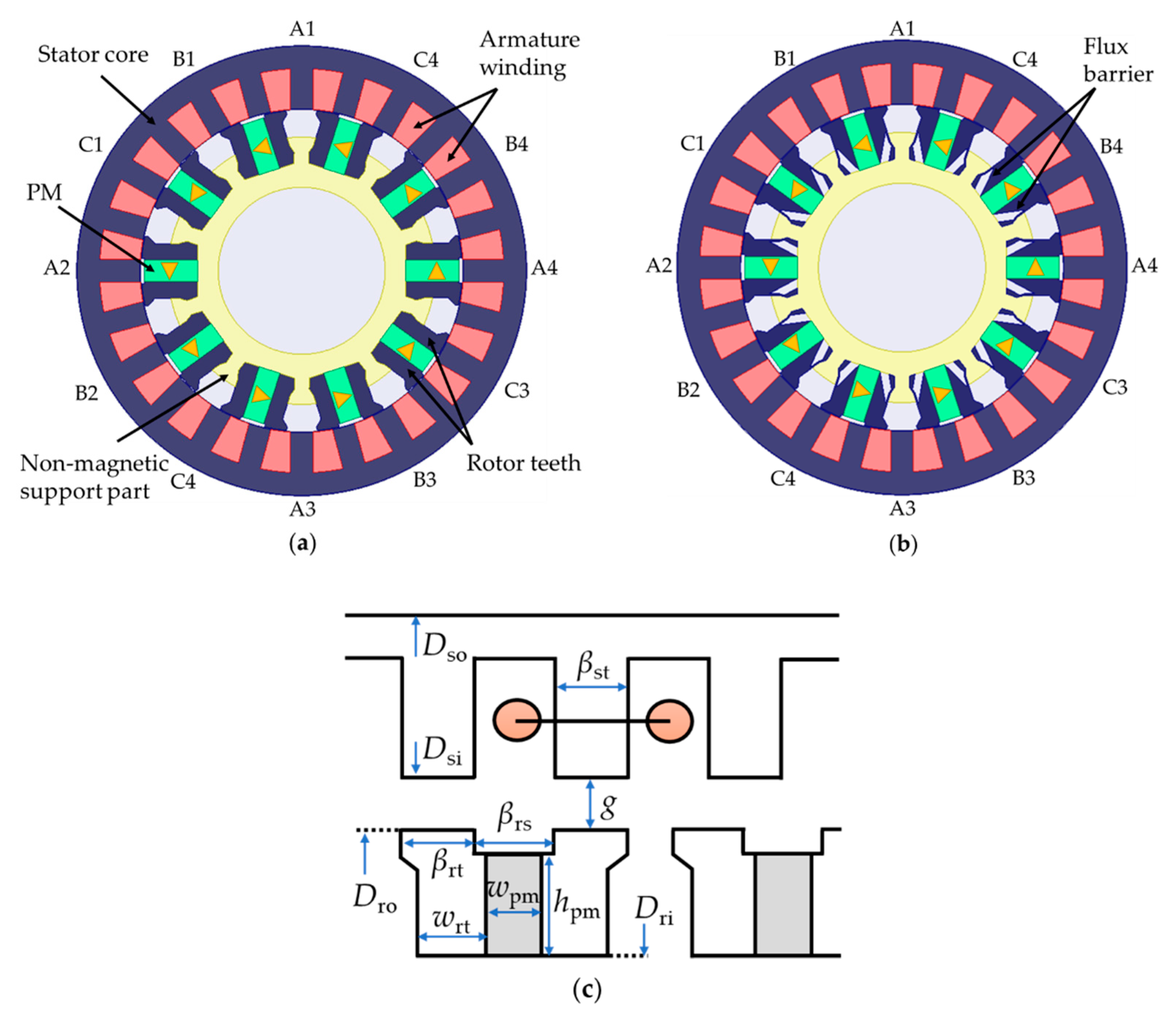
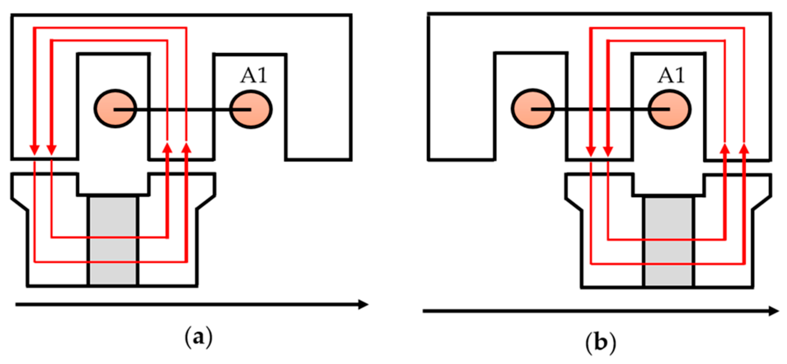
2. Machine Topology and Working Principle

The conventional RPM-FS machine used in this work was adopted from [18]. This structure was chosen because it indicates a high-range torque capability when compared to other FSPM machines, as well as the fact that its output profiles have been experimentally validated. The suitability of this structure for use in the EV and HEV driving systems was also claimed due to its advantages, including a wide speed regulation range, strong overload capability, good thermal dissipation, high magnetic saturation, and low noise. Figure 1a depicts the conventional three-phase RPM-FS machine with 24-stator/10-rotor poles, while Figure 1b depicts the RPM-FS machine with the optimal flux barriers inserted. It is worth noting that the RPM-FS structure’s operating principle remains unchanged after the proposed flux barrier design is installed. The stator of RPM-FS machines contains salient-pole iron laminations with PMs installed with the same magnetization direction to satisfy the principle of flux switching. The structural parameters of these two structures are shown in Figure 1c, while their values are listed in Table 1.
The working principle of the three-phase rotor-PM machine is presented in Figure 2. When the rotor teeth are rotated from position A at 0 electric degrees (Figure 2a) to position B at 150 electric degrees (Figure 2b), it is interlaced with the stator teeth to alternate the polarity of the PM flux-linkage. The magnitude and polarity of PM flux-linkage will therefore be changed occasionally when the rotor rotates continuously. To achieve the maximum back-EMF of phase A, winding coils A1 (A2) and A3 (A4) are connected in series. It should be noted that winding coil A1 (A3) is contrary to A2 (A4). Then, the back-EMF vectors of all teeth in phase A are superposed. The back-EMF vectors of phases B and C can be constructed using the same principles as phase A.

3. Flux Barrier Design and Optimization

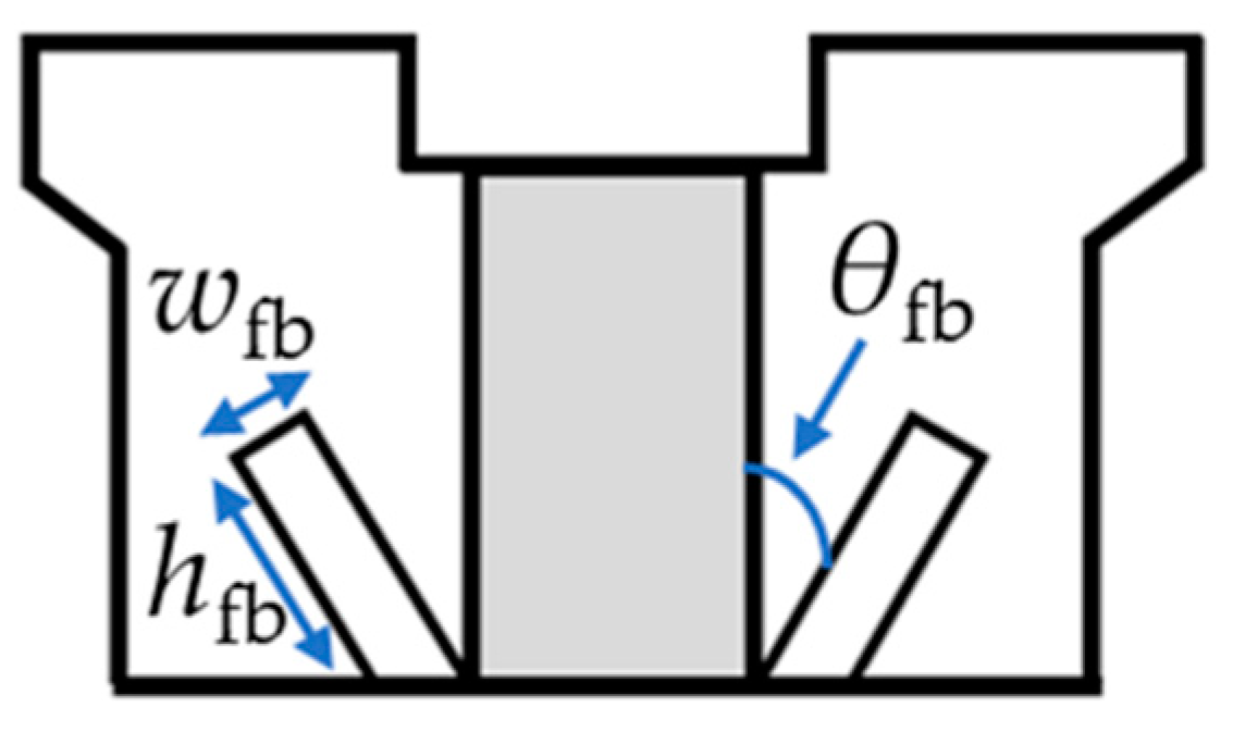
3.1. Flux Barrier Design

In this work, the flux barriers are proposedly to be inserted in the rotor of the conventional RPM-FS machine as shown in Figure 3 and are located at the ends of PMs along the rotor inner diameter. This design aims to control the magnetic field distribution in the structure. As shown in Figure 3, the flux barriers were installed at the ends of PMs along the rotor inner diameter. The shape of the flux barriers is designed and optimized by varying its geometrical parameters, including the tiled angle, θfb, height, hfb, and thickness, wfb, as defined in Figure 3. These design parameters were optimized using the RS methodology, in which the optimization process is described in Section 3.2. The proposed flux barriers were expected to improve the torque capability and losses of the machine by increasing the density of flux passing from rotor to stator teeth and the working harmonic of the torque contribution while decreasing leakage flux.

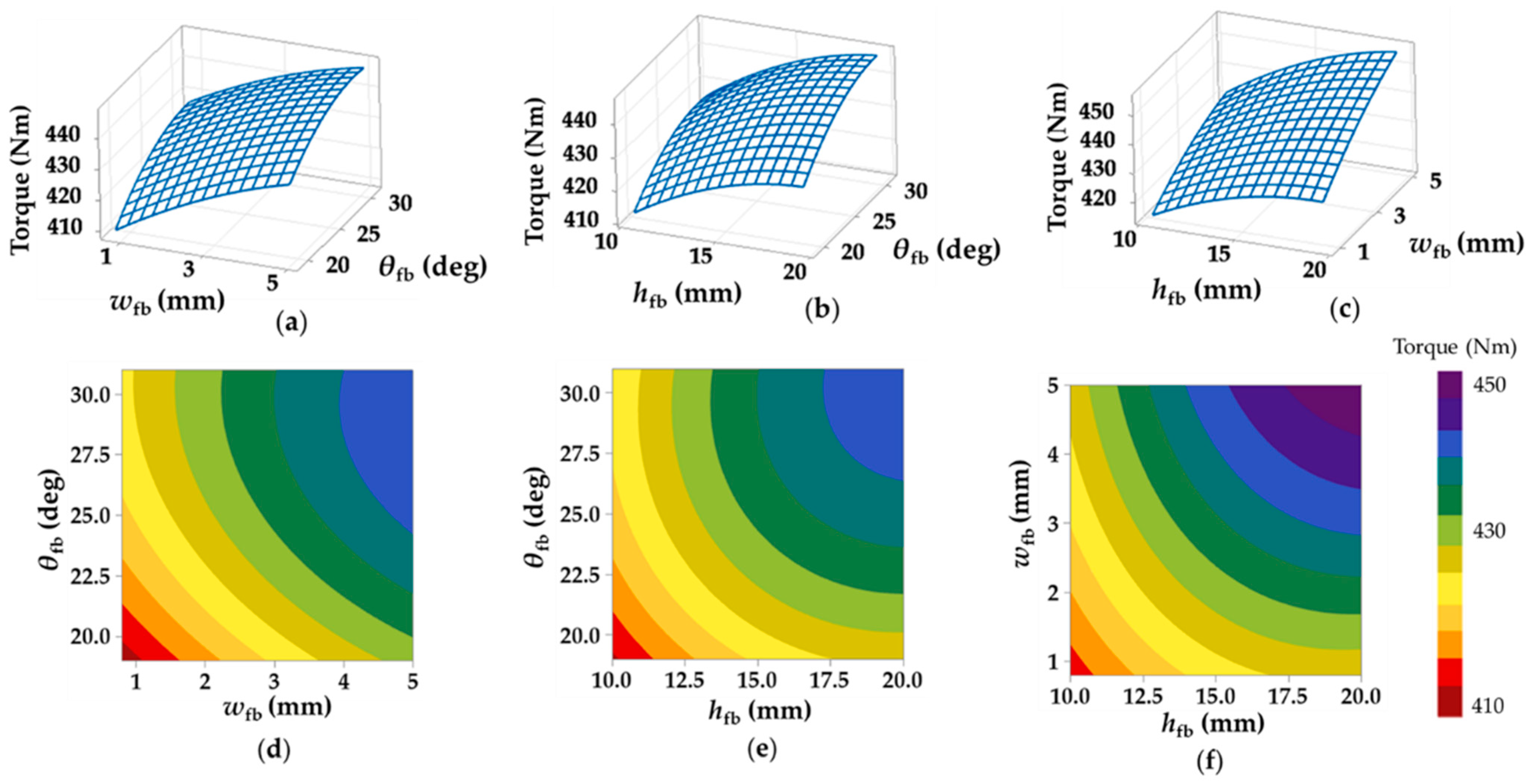
3.2. Optimization of Flux Barrier Geometry Using RS Methodology

As previously stated, three design parameters of the flux barrier, including θfb, hfb, and wfb, were optimized using the RS methodology with the objective function of torque maximization. In general, the electromagnetic torque of the RPM-FS machine, Te, is produced from the interaction of magnetic and electrical loading, as expressed by Equation (1) [16].
T e = π 4 D si 2 l a v B v A v cos ϕ v
where Dsi is the stator inner diameter, la is the stack length, and ϕv is the vth air-gap flux density harmonic angle between the magnetic loading, Bv, and the electrical loading, Av.
The RS methodology is a technique for demonstrating the relationship between the response and the model values by determining the optimal mathematical and statistical solution. This method is typically suitable for solving the optimization problems with moderate design variables. The expression of the corresponding response, Y, is given by:
Y = β 0 + k = 1 K β k X k + k = 1 K β k X k 2 + j < k β jk X k X j
where Xk and Xj are the coded values of design variables. β0, βk, and βjk are the regression coefficients of design variables. k and j are the linear and quadratic coefficients, respectively. The flowchart of design process using RS methodology is shown in Figure 4.
In our proposed flux barrier design, the range of each design variable was determined based on the condition that the narrowest segment of the lamination must be greater than 1 mm to ensure the robustness of machine prototype, as shown in Table 2. Then, the surface plot of average torque with varying design variables was established to select the optimal barrier shape providing the maximum torque capability.
Figure 5 depicts the 3D surfaces and contour plots of the RS methodology, demonstrating the interacting influences between torque performance and combinations of flux barrier’s design parameters. From the results, a variation of θfb seems to have the highest influence on the torque performance, especially at higher values of wfb and hfb. It is also observed that varying wfb and hfb at lower θfb value has a lower influence on torque magnitude than varying them at higher θfb value. With increasing the θfb, results show that the output torque increases until it reaches its peak point at about 28 degrees, and thereafter it reduces with higher value of θfb. When increasing wfb the flux barriers, it was found that the output torque was significantly enhanced even with a smaller value as 0.75 mm, and gradually improved further at wfb above 4 mm. The torque also increased significantly with the increment of the barrier height. However, the increase is restricted and can continue only until the barrier has reached its maximum possible height, which is limited by boundary conditions. We also observed that if we kept the wfb (hfb) at a constant value and varied hfb (wfb), a variation of hfb (wfb) had less influence on the output torque at smaller wfb (hfb) but indicated that it has a higher influence at larger wfb (hfb). This implies that the magnetic flux circulation in the machine structure can be strongly impacted at higher values of both parameters. Based on the results, the optimal geometry of flux barriers was selected to be wfb, = 4.88 mm, hfb, = 21.89 mm, and θfb = 28.14 degrees. The RPM-FS machine with a rotor structure with this optimal flux barrier design can produce an output torque of up to 450 Nm, which is significantly greater than the torque that would have been produced by a RPM-FS machine with the conventional rotor structure. The performance of the RPM-FS machine with the optimal flux barrier inserted is evaluated and compared to the conventional structure, as detailed in the following section.

4. Performance Evaluation

In this section, the performance of the proposed RPM-FS machine with optimal flux barrier design is evaluated using 2D FE analysis and compared to the conventional structure. The characteristics and performance of the machine is evaluated through the no-load EMF, THD, cogging torque, air-gap flux density, electromagnetic torque, and losses. The efficiency is characterized at a rated speed of 1200 rpm.

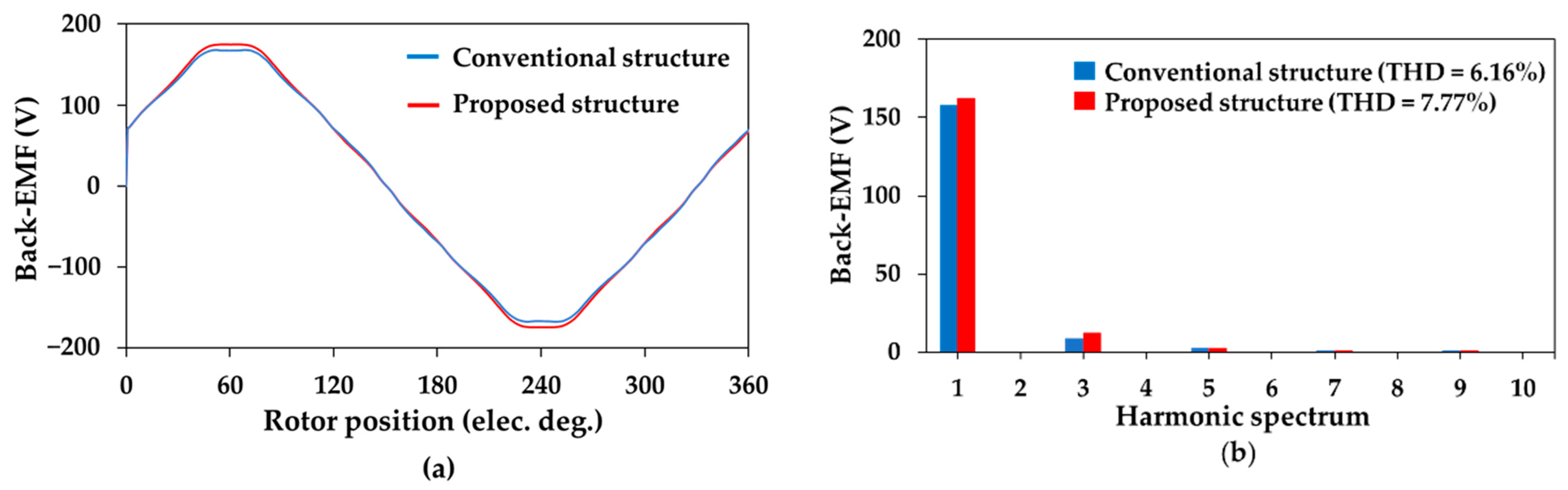
4.1. No-Load Performance

The open-circuit phase back EMF waveforms of the proposed RPM-FS machine and the conventional RPM-FS machine are shown in Figure 6a, while their spectrum is presented in Figure 6b. It is clearly observed that the EMF of the RPM-FS machine with the optimal flux barriers inserted is improved by about 2.4% when compared to the conventional structure, which reaches 124 Vrms. This improved EMF indicates that improved torque performance is possible. The spectrum analysis reveals that the optimal model contains the THD of 7.77%, which is insignificantly increased from the conventional machine (6.16%). The cogging torque waveforms shown in Figure 7 reveal that the proposed RPM-FS machine has a slightly larger cogging torque than the conventional machine, and its peak-to-peak value is increased from 1.86 to 2.18 Nm.

4.2. Air-Gap Flux Density

In this section, an analysis of the on-load air-gap flux density at 200 A-rated current is conducted. Figure 8 depicts a comparison of the magnetic flux distributions of two machines. It is clear that the optimal RPM-FS structure has significantly less flux leakage than the initial structure, particularly around the rotor teeth. Moreover, flux barriers increase the saturation of the rotor partial region while maintaining the main flux lines. This implies better magnet utilization caused by the insertion of the flux barriers, which could be a contributing factor to the torque performance improvement. Figure 9 illustrates the on-load air-gap flux density as a function of rotor position, including its harmonic spectrum. It is seen that the insertion of the flux barriers can alter the harmonic profile. Based on the analysis of the air-gap flux density, the working harmonics can be obtained by taking into account the number of stator slots and rotor teeth [31]. For the two RPM-FS structures focused on in this work, the main working harmonics contributions to the torque were found to be 10th, 14th, and 34th harmonics, while 14th and 34th harmonic orders were contributed to the PM eddy current loss generation mechanism [14]. According to the RPM-FS machine structure, the electromagnetic torque is theoretically produced by the interaction of the magnetic and electrical loading harmonics with the same order and rotating speed in the airgap field [14]. The magnitude of torque can be determined by taking into account the machine’s volume, harmonic angle between magnetic and electrical loadings, and split ratio [14]. In our proposed optimal RPM-FS structure, it was found that the torque contributions of the 10th, 14th, and 34th harmonics were 83.1%, 11.5%, and 21.4%, respectively. Therefore, an increase in the 10th harmonic is dominant in improving the overall torque magnitude and can be considered one of the main reasons behind the torque improvement of the proposed structure.

4.3. On-Load Torque Performance

A comparison of torque performance between the initial and optimal models is demonstrated in Figure 10. To provide a fair comparison of on-load performance, the rated current of 200 A was set according to rated condition of the conventional RPM-FS machine. Obviously, the average torque of the optimal structure reaches 450 Nm, which is 6% higher than the initial value. Meanwhile, the insignificantly higher torque ripple, Trip, of the optimal model is observed. The result shows that the torque ripple is slightly increased to 3.8% from 2.9% of the conventional structure. Therefore, the proposed RPM-FS structure clearly outperforms the conventional structure in terms of torque capability, in which its better magnet utilization and improved working harmonics are the rationale for this torque improvement. It is also worth noting that 6% torque improvement observed with the rotor barrier significantly outweighs any variation due to fabricating tolerances.

4.4. Losses Analysis and Efficiency

This section demonstrates a comparison of losses and efficiency of the initial and proposed RPM-FS machines operated with the rated current of 200 A and rated speed of 1200 rpm. Table 3 shows the output characteristics of both RPM-FS machines. It is seen that the proposed structure has a slightly lower core loss than the conventional structure since the insertion of the flux barriers improves the utilization of the rotor core. It is clear that the proposed RPM-FS machine uses a slightly lower core weight than the convention structure due to the replacement of steel with barriers. With lower leakage fluxes in the proposed rotor structure, the core is better utilized, and as a result of the slightly lower weight, the core losses exhibit a reduction even though the magnetic flux densities are higher. Notably, it was found that the proposed structure exhibits 10% lower PM eddy current loss than the conventional structure since all working harmonics contributions to the PM eddy current loss generation mechanism, namely, 14th and 34th harmonic orders, were reduced. The result also shows that the insertion of flux barriers yields an improvement in the output power. Overall, the efficiency of the proposed RPM-FS machine is 1.02 times of that of the conventional structure, which reaches 90.8%. When compared to other RPM-FS machines existing in the literature, the torque magnitude produced by the proposed machine is in a high range. It is therefore a capable machine for use in EV and HEV applications. Finally, an improvement of efficiency and the experimental investigation are recommended for future research. The rotor structure, stator configuration, winding configuration, and PM material are suggested as key design parameters for achieving higher efficiency.

5. Conclusions

This paper introduces an optimal flux barrier design for improving torque performance of the RPM-FS machine. The magnetic flux barriers were inserted on the rotor of the RPM-FS machine to improve magnetic flux circulation ability in the machine structure. The flux barrier’s shape was optimized using the RS methodology. According to the FE analysis, the proposed machine indicated a 2.4% higher EMF with a minor increase in cogging torque. Notably, torque improvement of up to 6% was reported. The analysis revealed that the improved torque quality was caused by the reduction in magnetic flux leakage, the improved magnetic saturation capability, and the enhancement of the working harmonic of air-gap flux density. Furthermore, the installation of flux barriers reduced PM eddy current loss by 10% due to lower leakage fluxes in the rotor. When compared to the conventional structure, the overall efficiency of the proposed RPM-FS machine increased by 1.02 times. Hence, the proposed RPM-FS machine is capable of being used in EV and HEV applications. Future research and development activities may move toward an improvement of efficiency in which an adjustment of the rotor structure, stator configuration, winding configuration, and PM material are suggested as the key design parameters.

Author Contributions

Conceptualization, C.N. and P.K.; Methodology, C.N.; Software, C.N.; Data curation, C.N.; Formal analysis, C.N.; Writing—original draft, C.N.; Visualization, P.S., S.C., N.F. and A.S.; Validation, P.K.; Supervision, P.K.; Funding acquisition, P.K.; Writing—review and editing, P.K. All authors have read and agreed to the published version of the manuscript.

Funding

This research was funded by the Fundamental Fund of Khon Kaen University and the Research Fund of the Faculty of Engineering, Khon Kaen University, under the Research Scholarship for M.Eng. Students project under Contract No. M-Eng.-EE-001/2564.

Data Availability Statement

Not applicable.

Conflicts of Interest

The authors declare no conflict of interest.

References

  1. Chau, K.T.; Chan, C.C.; Liu, C. Overview of Permanent-Magnet Brushless Drives for Electric and Hybrid Electric Vehicles. IEEE Trans. Ind. Electron. 2008, 55, 2246–2257. [Google Scholar] [CrossRef] [Green Version]
  2. Belkhier, Y.; Shaw, R.N.; Bures, M.; Islam, M.R.; Bajaj, M.; Albalawi, F.; Alqurashi, A.; Ghoneim, S.S. Robust Interconnection and Damping Assignment Energy-Based Control for a Permanent Magnet Synchronous Motor Using High Order Sliding Mode Approach and Nonlinear Observer. Energy Rep. 2022, 8, 1731–1740. [Google Scholar] [CrossRef]
  3. Cheng, M.; Hua, W.; Zhang, J.; Zhao, W. Overview of Stator-Permanent Magnet Brushless Machines. IEEE Trans. Ind. Electron. 2011, 58, 5087–5101. [Google Scholar] [CrossRef]
  4. Lounthavong, V.; Sriwannarat, W.; Siritaratiwat, A.; Khunkitti, P. Optimal Stator Design of Doubly Salient Permanent Magnet Generator for Enhancing the Electromagnetic Performance. Energies 2019, 12, 3201. [Google Scholar] [CrossRef] [Green Version]
  5. Sriwannarat, W.; Khunkitti, P.; Janon, A.; Siritaratiwat, A. An Improvement of Magnetic Flux Linkage in Electrical Generator Using the Novel Permanent Magnet Arrangement. Acta Phys. Pol. A 2018, 133, 642–644. [Google Scholar] [CrossRef]
  6. Sriwannarat, W.; Seangwong, P.; Lounthavong, V.; Khunkitti, S.; Siritaratiwat, A.; Khunkitti, P. An Improvement of Output Power in Doubly Salient Permanent Magnet Generator Using Pole Configuration Adjustment. Energies 2020, 13, 4588. [Google Scholar] [CrossRef]
  7. Sriwannarat, W.; Siritaratiwat, A.; Khunkitti, P. Structural Design of Partitioned Stator Doubly Salient Permanent Magnet Generator for Power Output Improvement. Adv. Mater. Sci. Eng. 2019, 2019, 2189761. [Google Scholar] [CrossRef] [Green Version]
  8. Zhu, Z.Q.; Chen, J.T. Advanced Flux-Switching Permanent Magnet Brushless Machines. IEEE Trans. Magn. 2010, 46, 1447–1453. [Google Scholar] [CrossRef]
  9. Thomas, A.S.; Zhu, Z.Q.; Jewell, G.W. Comparison of Flux Switching and Surface Mounted Permanent Magnet Generators for High-Speed Applications. IET Electr. Syst. Transp. 2011, 1, 111–116. [Google Scholar] [CrossRef]
  10. Shi, Y.; Jian, L.; Wei, J.; Shao, Z.; Li, W.; Chan, C.C. A New Perspective on the Operating Principle of Flux-Switching Permanent-Magnet Machines. IEEE Trans. Ind. Electron. 2015, 63, 1425–1437. [Google Scholar] [CrossRef]
  11. Shao, L.; Hua, W.; Zhu, Z.Q.; Tong, M.; Zhao, G.; Yin, F.; Wu, Z.; Cheng, M. Influence of Rotor-Pole Number on Electromagnetic Performance in 12-Phase Redundant Switched Flux Permanent Magnet Machines for Wind Power Generation. IEEE Trans. Ind. Appl. 2017, 53, 3305–3316. [Google Scholar] [CrossRef]
  12. Su, P.; Hua, W. Performance Comparison between Rotor Flux-Switching and Stator Flux-Switching Machines Considering Local Demagnetization. AIP Adv. 2017, 7, 056641. [Google Scholar] [CrossRef] [Green Version]
  13. Su, P.; Hua, W.; Wu, Z.; Chen, Z.; Zhang, G.; Cheng, M. Comprehensive Comparison of Rotor Permanent Magnet and Stator Permanent Magnet Flux-Switching Machines. IEEE Trans. Ind. Electron. 2018, 66, 5862–5871. [Google Scholar] [CrossRef]
  14. Su, P.; Hua, W.; Wu, Z.; Han, P.; Cheng, M. Analysis of the Operation Principle for Rotor-Permanent-Magnet Flux-Switching Machines. IEEE Trans. Ind. Electron. 2017, 65, 1062–1073. [Google Scholar] [CrossRef]
  15. Su, P.; Hua, W.; Hu, M.; Chen, Z.; Cheng, M.; Wang, W. Analysis of PM Eddy Current Loss in Rotor-PM and Stator-PM Flux-Switching Machines by Air-Gap Field Modulation Theory. IEEE Trans. Ind. Electron. 2019, 67, 1824–1835. [Google Scholar] [CrossRef]
  16. Su, P.; Hua, W.; Hu, M.; Wu, Z.; Si, J.; Chen, Z.; Cheng, M. Analysis of Stator Slots and Rotor Pole Pairs Combinations of Rotor-Permanent Magnet Flux-Switching Machines. IEEE Trans. Ind. Electron. 2019, 67, 906–918. [Google Scholar] [CrossRef]
  17. Eduku, S.; Chen, Q.; Xu, G.; Liu, G.; Liao, J.; Zhang, X. A New Fault-Tolerant Rotor Permanent Magnet Flux-Switching Motor. IEEE Trans. Transp. Electrif. 2022, 8, 3606–3617. [Google Scholar] [CrossRef]
  18. Su, P.; Hua, W.; Zhang, G.; Chen, Z.; Cheng, M. Analysis and Evaluation of Novel Rotor Permanent Magnet Flux-Switching Machine for EV and HEV Applications. IET Electr. Power Appl. 2017, 11, 1610–1618. [Google Scholar] [CrossRef]
  19. Sanada, M.; Hiramoto, K.; Morimoto, S.; Takeda, Y. Torque Ripple Improvement for Synchronous Reluctance Motor Using an Asymmetric Flux Barrier Arrangement. IEEE Trans. Ind. Appl. 2004, 40, 1076–1082. [Google Scholar] [CrossRef]
  20. Barcaro, M.; Bianchi, N.; Magnussen, F. Rotor Flux-Barrier Geometry Design to Reduce Stator Iron Losses in Synchronous IPM Motors under FW Operations. IEEE Trans. Ind. Appl. 2010, 46, 1950–1958. [Google Scholar] [CrossRef]
  21. Yamazaki, K.; Kumagai, M.; Ikemi, T.; Ohki, S. A Novel Rotor Design of Interior Permanent-Magnet Synchronous Motors to Cope with Both Maximum Torque and Iron-Loss Reduction. IEEE Trans. Ind. Appl. 2013, 49, 2478–2486. [Google Scholar] [CrossRef]
  22. Zhao, W.; Zhao, F.; Lipo, T.A.; Kwon, B.-I. Optimal Design of a Novel V-Type Interior Permanent Magnet Motor with Assisted Barriers for the Improvement of Torque Characteristics. IEEE Trans. Magn. 2014, 50, 8104504. [Google Scholar] [CrossRef]
  23. Sarani, E.; Vaez-Zadeh, S. Line Start Permanent Magnet Motors with Double-Barrier Configuration for Magnet Conservation and Performance Improvement. IET Electr. Power Appl. 2017, 11, 1656–1663. [Google Scholar] [CrossRef]
  24. Yamazaki, K.; Kato, Y.; Ikemi, T.; Ohki, S. Reduction of Rotor Losses in Multilayer Interior Permanent-Magnet Synchronous Motors by Introducing Novel Topology of Rotor Flux Barriers. IEEE Trans. Ind. Appl. 2014, 50, 3185–3193. [Google Scholar] [CrossRef]
  25. Choi, G.; Jahns, T.M. Reduction of Eddy-Current Losses in Fractional-Slot Concentrated-Winding Synchronous PM Machines. IEEE Trans. Magn. 2016, 52, 8105904. [Google Scholar] [CrossRef]
  26. Luo, J.; Zhao, W.; Ji, J.; Zheng, J.; Zhang, Y.; Ling, Z.; Mao, J. Reduction of Eddy-Current Loss in Flux-Switching Permanent-Magnet Machines Using Rotor Magnetic Flux Barriers. IEEE Trans. Magn. 2017, 53, 2300605. [Google Scholar] [CrossRef]
  27. Zhao, W.; Pan, X.; Ji, J.; Xu, L.; Zheng, J. Analysis of PM Eddy Current Loss in Four-Phase Fault-Tolerant Flux-Switching Permanent-Magnet Machines by Air-Gap Magnetic Field Modulation Theory. IEEE Trans. Ind. Electron. 2019, 67, 5369–5378. [Google Scholar] [CrossRef]
  28. Sayed, E.; Yang, Y.; Bilgin, B.; Bakr, M.H.; Emadi, A. A Comprehensive Review of Flux Barriers in Interior Permanent Magnet Synchronous Machines. IEEE Access 2019, 7, 149168–149181. [Google Scholar] [CrossRef]
  29. Ishikawa, K.; Kitagawa, W.; Takeshita, T. Shape Optimization of Flux Barriers in IPMSM by Using Polygon Model Method with GP. In Proceedings of the 2014 International Conference on Electrical Machines (ICEM), Berlin, Germany, 2–5 September 2014; pp. 1403–1408. [Google Scholar]
  30. Pan, Z.; Yang, K.; Wang, X. Optimal Design of Flux-Barrier to Improve Torque Performance of IPMSM for Electric Spindle. In Proceedings of the 2015 18th International Conference on Electrical Machines and Systems (ICEMS), Pattaya, Thailand, 25–28 October 2015; pp. 773–778. [Google Scholar]
  31. Yang, H.; Li, Y.; Lin, H.; Zhu, Z.Q.; Lyu, S. Principle Investigation and Performance Comparison of Consequent-Pole Switched Flux PM Machines. IEEE Trans. Transp. Electrif. 2020, 7, 766–778. [Google Scholar] [CrossRef]
  32. Li, Y.; Yang, H.; Lin, H. Investigation of Torque Improvement Mechanism in Emerging Switched Flux PM Machines. IEEE J. Emerg. Sel. Top. Power Electron. 2020, 10, 1860–1869. [Google Scholar] [CrossRef]
  33. Fang, L.; Kim, S.-I.; Kwon, S.-O.; Hong, J.-P. Novel Double-Barrier Rotor Designs in Interior-PM Motor for Reducing Torque Pulsation. IEEE Trans. Magn. 2010, 46, 2183–2186. [Google Scholar] [CrossRef]
  34. Bianchi, N.; Bolognani, S.; Bon, D.; Dai Pre, M. Rotor Flux-Barrier Design for Torque Ripple Reduction in Synchronous Reluctance and PM-Assisted Synchronous Reluctance Motors. IEEE Trans. Ind. Appl. 2009, 45, 921–928. [Google Scholar] [CrossRef]
  35. Kim, K.-C. A Novel Method for Minimization of Cogging Torque and Torque Ripple for Interior Permanent Magnet Synchronous Motor. IEEE Trans. Magn. 2014, 50, 793–796. [Google Scholar] [CrossRef]
  36. Ge, X.; Zhu, Z.Q.; Li, J.; Chen, J. A Spoke-Type IPM Machine with Novel Alternate Airspace Barriers and Reduction of Unipolar Leakage Flux by Step-Staggered Rotor. IEEE Trans. Ind. Appl. 2016, 52, 4789–4797. [Google Scholar] [CrossRef]
  37. Ren, W.; Xu, Q.; Li, Q. Asymmetrical V-Shape Rotor Configuration of an Interior Permanent Magnet Machine for Improving Torque Characteristics. IEEE Trans. Magn. 2015, 51, 8113704. [Google Scholar] [CrossRef]
  38. Yamazaki, K.; Ohki, S.; Nezu, A.; Ikemi, T. Development of Interior Permanent Magnet Motors—Reduction of Harmonic Iron Losses by Optimizing Rotor Structures. In Proceedings of the 2007 IEEE International Electric Machines & Drives Conference, Antalya, Turkey, 3–5 May 2007; Volume 1, pp. 489–494. [Google Scholar]
  39. Chen, Y.; Zhuang, J.; Ding, Y.; Li, X. Optimal Design and Performance Analysis of Double Stator Multi-Excitation Flux-Switching Machine. IEEE Trans. Appl. Supercond. 2019, 29, 0601205. [Google Scholar] [CrossRef]
  40. Zhu, X.; Fan, D.; Mo, L.; Chen, Y.; Quan, L. Multiobjective Optimization Design of a Double-Rotor Flux-Switching Permanent Magnet Machine Considering Multimode Operation. IEEE Trans. Ind. Electron. 2019, 66, 641–653. [Google Scholar] [CrossRef]
  41. Kim, S.I.; Kim, Y.K.; Lee, G.H.; Hong, J.P. A Novel Rotor Configuration and Experimental Verification of Interior Pm Synchronous Motor for High-Speed Applications. IEEE Trans. Magn. 2012, 48, 843–846. [Google Scholar] [CrossRef]
  42. Jung, J.W.; Lee, S.H.; Lee, G.H.; Hong, J.P.; Lee, D.H.; Kim, K.N. Reduction Design of Vibration and Noise in IPMSM Type Integrated Starter and Generator for HEV. IEEE Trans. Magn. 2010, 46, 2454–2457. [Google Scholar] [CrossRef]
  43. Im, Y.H.; Hwang, S.I.; Jang, S.M.; Choi, J.Y.; Choi, J.H. Analysis of Torque Pulsation Considering Interior Permanent Magnet Rotor Rib Shape Using Response Surface Methodology. IEEE Trans. Magn. 2012, 48, 979–982. [Google Scholar] [CrossRef]
  44. Lee, J.H.; Lee, I.K.; Cho, Y.H.; Yun, T.W. Characteristics Analysis and Optimum Design of Anisotropy Rotor Synchronous Reluctance Motor Using Coupled Finite Element Method and Response Surface Methodology. IEEE Trans. Magn. 2009, 45, 4696–4699. [Google Scholar] [CrossRef]
  45. Lee, B.H.; Hong, J.P.; Lee, J.H. Optimum Design Criteria for Maximum Torque and Efficiency of a Line-Start Permanent-Magnet Motor Using Response Surface Methodology and Finite Element Method. IEEE Trans. Magn. 2012, 48, 863–866. [Google Scholar] [CrossRef]
  46. Choi, Y.C.; Kim, H.S.; Lee, J.H. Optimum Design Criteria for Maximum Torque Density and Minimum Torque Ripple of SynRM According to the Rated Wattage Using Response Surface Methodology. IEEE Trans. Magn. 2008, 44, 4135–4138. [Google Scholar] [CrossRef]
Figure 1. Topologies of the 24/10-pole RPM-FS machines. (a) Conventional structure. (b) Proposed structure. (c) Key design parameters.
Energies 15 08429 g001
Figure 2. Working principle of the RPM-FS machine (a) rotor position A (at 0 electric degrees), and (b) rotor position B (at 150 electric degrees).
Energies 15 08429 g002
Figure 3. Design variables of the proposed flux barriers.
Energies 15 08429 g003
Figure 4. A flowchart of design process using RS methodology.
Energies 15 08429 g004
Figure 5. Surfaces and contour plots of average torque resulting from RS methodology of (a,d) wfb versus θfb; (b,e) hfb versus θfb; (c,f) wfb versus hfb.
Energies 15 08429 g005
Figure 6. (a) Open-circuit phase back-EMF waveforms and (b) its spectrum.
Energies 15 08429 g006
Figure 7. Comparison of cogging torque.
Energies 15 08429 g007
Figure 8. Magnetic flux distribution of (a) the conventional structure and (b) the optimal structure of RPM-FS machines.
Energies 15 08429 g008
Figure 9. Air-gap flux density. (a) Waveforms. (b) Harmonic spectrum.
Energies 15 08429 g009
Figure 10. Output torques of two RPM-FS machines.
Energies 15 08429 g010
Table 1. Structural parameters of the conventional and the proposed optimal RPM-FS machines.
ParametersConventional StructureProposed Structure
Number of stator pole24
Number of rotor pole10
Stack length (mm)83.56
Stator outer diameter, Dso (mm)269
Stator inner diameter, Dsi (mm)193.68
Stator tooth arc, βst (degree)8.1
Air-gap length, g (mm)0.73
Rotor outer diameter, Dro (mm)192.22
Rotor inner diameter, Dri (mm)124.94
Rotor tooth thickness, wrt (mm)10.03
Rotor tooth arc, βrt (degree)8.1
Rotor slot arc, βrs (degree)9.0
PM thickness, wpm (mm)12.89
PM height, hpm (mm)31.64
Flux barrier thickness, wfb (mm)-4.88
Flux barrier height, hfb (mm)-21.89
Flux barrier angle θfb (deg)-28.14
Iron typeM19_29G
PM typeN36Z_20
Number of turns per phase72
Table 2. Range of design variables.
Design VariablesRange
Flux barrier thickness, wfb (mm)0.75–5
Flux barrier height, hfb (mm)7.5–22.5
Flux barrier angle, θfb (degree)20–30
Table 3. Performance comparison.
Machine’s ParametersConventional StructureProposed Structure
Rated current (A, rms)200
Rated speed (rpm)1200
Copper loss (W)4405
Core loss (W)256.6246.3
Eddy current loss (W)712643.8
Output torque (N.m)424.5450
Output power (W)53,340.356,524.5
Efficiency (%)89.3%90.8%
Publisher’s Note: MDPI stays neutral with regard to jurisdictional claims in published maps and institutional affiliations.

