
A Review of the Life Cycle Analysis Results for Different Energy Conversion Technologies
Abstract
:1. Introduction
2. Materials and Methods
3. Results of the Review
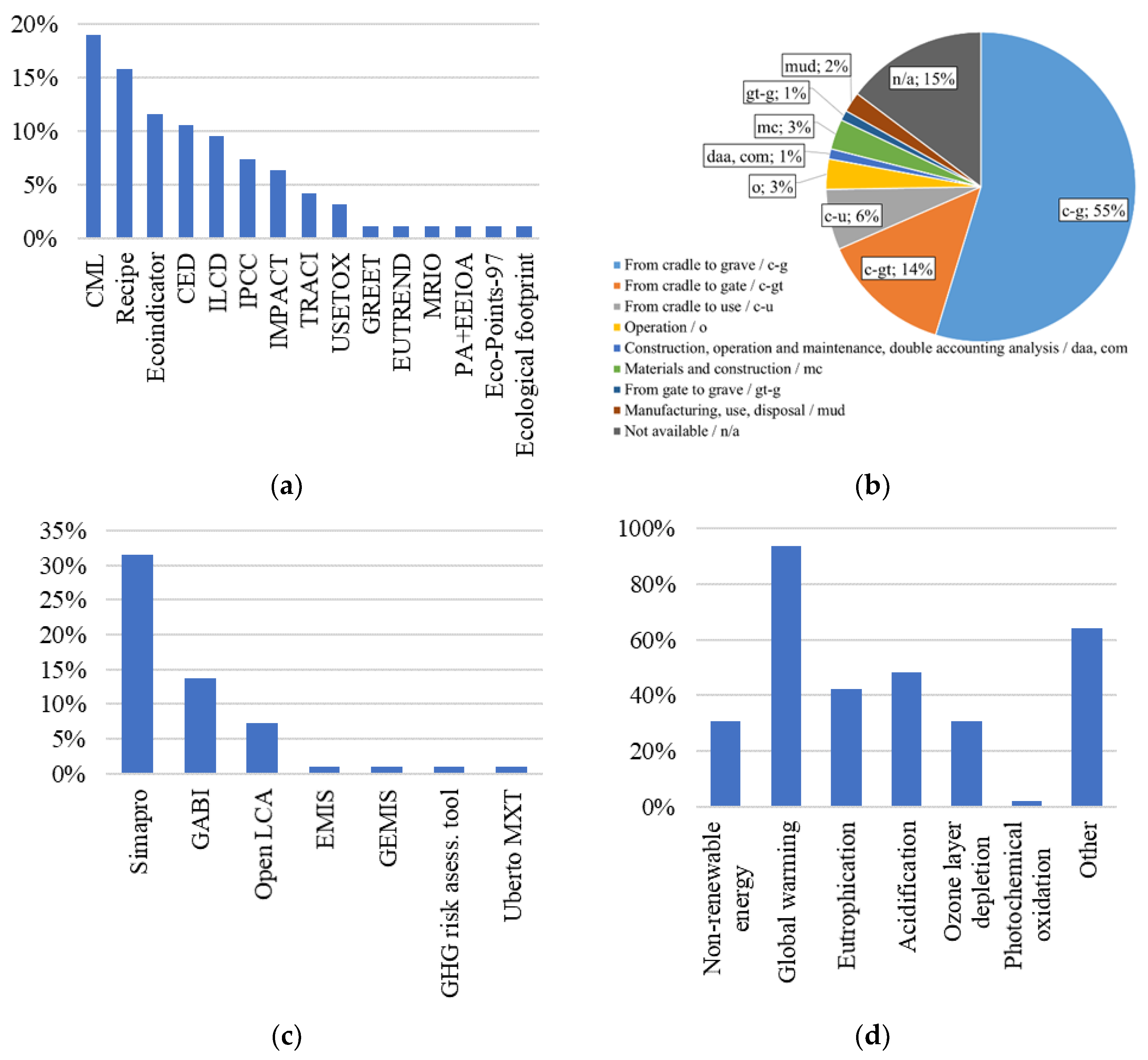
3.1. Methodological Aspects of the Studies Reviewed
3.2. Hydro Energy

| Source | Country, Comments | gCO2 eq/kWh.e |
|---|---|---|
| [11] | review | 3.7–237 |
| [13] | bGHG only | 160 |
| [12] | review, incl. dams | 4.5–152 |
| [18] | Thailand, micro | 52.7 |
| [19] | Myanmar, large scale, ROR | 31.17–39.23 |
| [12] | review, ROR | 0.3–13 |
| [12] | review, not incl. dams | avg. 2.9 (0.2–11.2) |
| [17] | China, mega scale | 7.6–9.12 |
| [16] | China | 3.1–3.7 |
| [14] | Peru, Andes, ROR | 2.06–2.42 |
| [15] | Europe, alpine non-alpine | 0.107–1.41 |
3.3. Wind Energy
3.4. Solar Energy
3.4.1. Photovoltaics
3.4.2. Solar Thermal Collectors
3.5. Geothermal Energy
3.6. Waste
3.7. Cogeneration
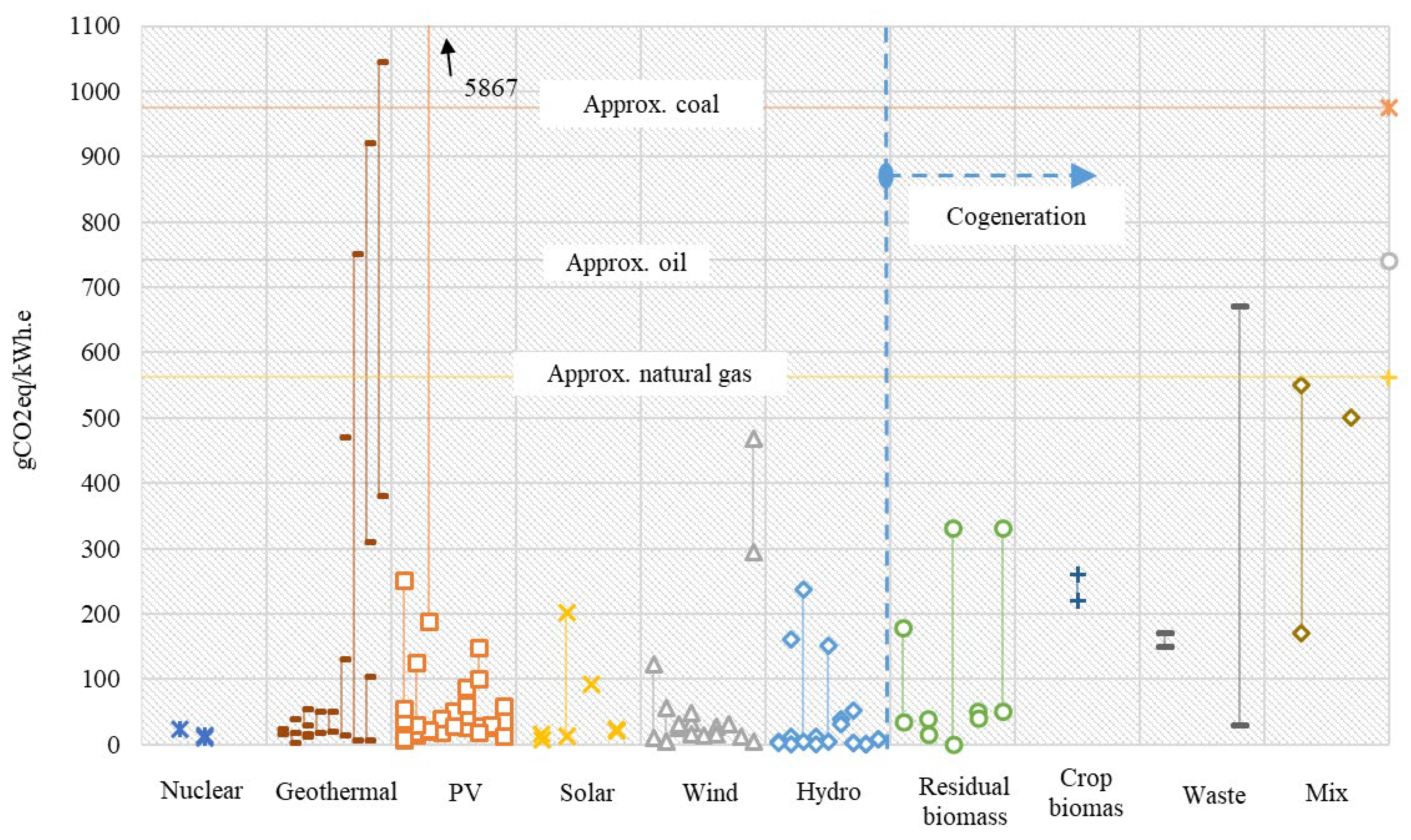
3.8. Results for Different Energy Conversion Technologies
4. Discussion
5. Conclusions
Author Contributions
Funding
Institutional Review Board Statement
Informed Consent Statement
Data Availability Statement
Conflicts of Interest
List of Acronyms
| a-Si | amorphous silicon PV technology |
| CCS | carbon capture and storage |
| CdTe | cadmium telluride PV technology |
| CED | cumulative energy demand |
| CExC | cumulative exergy consumption |
| c-g | from cradle to grave |
| c-gt | from cradle to gate |
| CHP | combined heat and power |
| CIGS | cadmium indium gallium selenium PV technology |
| CML | impact assessment method by Institute of Environmental Sciences at Leiden University |
| com | construction, operation, and maintenance |
| c-u | from cradle to use |
| daa | double accounting analysis |
| DSC | dye-sensitized PV technology |
| DHW | domestic hot water |
| EGS | enhanced geothermal systems |
| FU | functional unit |
| GHG | greenhouse gas |
| gt-g | from gate to grave |
| GWP | global warming potential |
| HT | hydrothermal plant |
| ILCD | International Reference Life Cycle Data System |
| IPCC | intergovernmental panel on climate change |
| kWh.e | kilowatt hours of electricity |
| kWh.t | kilowatt hours of thermal energy |
| LCA | life cycle assessment |
| LC-TEC | The Thermo Ecological Cost Life Cycle Assessment |
| mc | materials and construction |
| m-Si | multicrystalline silicon PV technology |
| mud | manufacturing, usage, disposal |
| non-RES | non-renewable energy sources |
| o | operation |
| OPV | organic cell PV technology |
| ORC | organic Rankine cycle |
| PA + EEIOA | process analysis + env extended IO analysis |
| PE | primary energy |
| PV | photovoltaics |
| QD | quantum dot PV technology |
| ReCiPe | impact assessment method by RIVM and Radboud University, CML, and PRé Consultants |
| RES | renewable energy sources |
| ROR | run-off-river |
| s-Si | conventional single-crystal PV technology |
| WtE | waste to energy |
Appendix A
| Source | Energy Sources | Converted Energy | Software | Impact Assessment Method | Boundaries | Impact Categories | ||||||||
|---|---|---|---|---|---|---|---|---|---|---|---|---|---|---|
| RES | Non-RES/Fossil | Electricity | Heat | Non-Renewable Energy | Global Warming | Eutrophication | Acidification | Ozone Layer Depletion | Photochemical Oxidation | Other | ||||
| 1 | 2 | 3 | 4 | 5 | 6 | 7 | 8 | 9 | 10 | 11 | 12 | 13 | 14 | 15 |
| [104] | + | + | n/a | ESA ReCiPe | daa, com | + | ||||||||
| [105] | + | partly | n/a | n/a | n/a | + | + | |||||||
| [18] | + | + | n/a | n/a | c-g | + | + | + | + | + | + | + | ||
| [13] | + | + | n/a | Biogenic GHG only as input to LCA | n/a | + | ||||||||
| [12] | + | + | n/a | n/a | + | |||||||||
| [19] | + | + | n/a | LCI, LCIA | c-g | + | + | + | + | |||||
| [14] | + | + | SimaPro v8.3.0.0 | ReCiPe | n/a | + | + | |||||||
| [15] | + | + | SimaPro 8.5 (ecoin vent) | ReCiPe 2016, Impact 2002+, Eco-points 97 | c-g | + | + | |||||||
| [106] | + | + | Umberto NXT; (ecoinvent v3.2) | ReCiPe, IPCC | c-g | + | + | + | + | |||||
| [107] | + | + | n/a | n/a | n/a | + | ||||||||
| [17] | + | + | GHG Risk Assess ment Tool | LCA ISO/TS 14067 | c-g | + | ||||||||
| [16] | + | + | SimaPro | CML2001 | n/a | + | + | + | + | |||||
| [21] | + | + | SimaPro 8.0.3.14 (Ecoinvent 3.01) | ReCiPe 2008 | c-g | + | + | |||||||
| [24] | + | + | n/a | PA + EEIOA | mc | + | + | |||||||
| [22] | + | + | n/a | n/a | c-g | + | ||||||||
| [23] | + | + | + | n/a | n/a | n/a | + | |||||||
| [25] | + | + | n/a | ILCD | n/a | + | + | |||||||
| [26] | + | + | n/a | n/a | c-g | + | ||||||||
| [108] | + | + | Simapro | Eco-indicator 99; + “original” | n/a | + | ||||||||
| [20] | + | + | n/a | n/a | c-g | + | ||||||||
| [109] | + | + | + | SimaPro | CML 2001 | o | + | + | + | |||||
| [110] | + | + | + | SimaPro 8.2 | n/a | c-g | + | + | + | + | ||||
| [111] | + | + | + | n/a | CML-IA baseline V3.02/EU25 | c-g | + | |||||||
| [112] | + | + | SimaPro 8 | ReCiPe, USEtox, and Ecological footprint | c-g | + | + | + | + | + | + | |||
| [113] | + | + | + | n/a | n/a | c-u | + | |||||||
| [35] | + | + | n/a | n/a | c-g | + | ||||||||
| [36] | + | + | SimaPro 7.1 | IPCC 1996 GWP 100a | c-g | + | + | |||||||
| [43] | + | + | GaBi | IPCC, USEtox, EUTREND, CML 2002 | c-g | + | + | + | ||||||
| [44] | + | + | n/a | MRIO-LCA | c-g | + | + | |||||||
| [7] | + | + | + | openLCA® 1.6.3 | Matrix-based LCA method | c-gt | + | |||||||
| [51] | + | + | + | + | Simapro 8 | TRACI 2.1 LCIA model | c-g | + | + | + | + | + | ||
| [36] | + | + | SimaPro 7.1 | IPCC 1996 GWP 100a | c-g | + | + | |||||||
| [45] | + | + | GaBi 4.0 | Ecoinvent 1.01 CML 2001 CED | c-u | + | ||||||||
| [34] | + | + | GaBi | Eco-Indicator ’95 | c-u | + | ||||||||
| [37] | + | + | GaBi 4.3 | CML 2001 | c-g | + | + | + | + | + | + | + | ||
| [42] | + | + | SimaPro 7.1.8 | CML 2001 | mud | + | + | + | + | + | + | |||
| [46] | + | + | GaBi | TRACI 2.1 | c-gt | + | + | + | ||||||
| [32] | + | + | n/a | Traci1.0 ReCiPe 2008 | mud | + | + | + | + | Etc | ||||
| [40] | + | + | SimaPro | ReCiPe 2008, CED | c-gt | + | ||||||||
| [29] | + | + | openLCA v1.4.2 | ReCiPe v1.0.5, CED | c-g | + | + | + | + | + | + | |||
| [47] | + | + | GaBi 6.0 | TRACI ReCiPe | c-gt | + | + | + | + | |||||
| [48] | + | + | SimaPor | n/a | c-gt | + | + | + | + | |||||
| [49] | + | + | GaBi 6.0 | ILCD | c-gt | + | + | + | + | + | + | |||
| [33] | + | + | SimaPro 8.5.2.0 | ReCiPe | c-g | + | + | + | + | + | ||||
| [50] | + | + | EMIS v5.7 | IPPC 2007 CED ReCiP USEtox EPB | c-gt | + | + | |||||||
| [60] | + | + | OpenLCA | ILCD 2011 Midpoint + ReCiPe 2016 | c-g | + | + | + | + | + | + | |||
| [67] | + | SimaPro | CML 2002 | c-u | + | + | + | |||||||
| [66] | + | + | n/a | CED | c-g | + | + | + | + | |||||
| [68] | + | + | + | SimaPro | CML 2011 CED | n/a | + | + | + | + | ||||
| [62] | + | + | + | n/a | GREET | c-u | + | |||||||
| [71] | + | + | + | Gabi | ILCD | c-g | + | + | + | + | + | + | ||
| [76] | + | + | + | n/a | IMPACT 2002+ | c-g | + | + | + | + | ||||
| [77] | + | + | + | n/a | CED | c-g | + | + | + | + | ||||
| [70] | + | + | + | SimaPro | CML-IA CED | c-gt | + | + | + | + | + | + | ||
| [72] | + | + | + | n/a | IPCC 2013 | gt-g | + | |||||||
| [69] | + | + | + | OpenLCA | ILCD 2011 | c-g | + | |||||||
| [75] | + | + | n/a | IMPACT 2002 + LCI | c-g | + | + | + | + | |||||
| [94] | + | + | + | n/a | CML-IA baseline V3.02/ EU25 | n/a | + | + | + | |||||
| [114] | + | + | + | n/a | Mix | c-g | + | + | + | + | + | |||
| [102] | + | + | + | n/a | n/a | n/a | + | + | + | + | + | + | + | |
| [92] | + | + | n/a | n/a | c-gt | + | ||||||||
| [98] | + | + | OpenLCA 1.10.1 | ILCD 2018 | c-g | + | + | + | + | + | + | + | ||
| [89] | + | + | Cold | SimaPro 8.0 | IPCC 2013 GWP 20a | c-gt | + | |||||||
| [115] | + | + | + | + | n/a | LC-TEC | c-g | + | + | |||||
| [101] | + | + | SimaPro 8.1 | CML IA baseline V3.02; Re-CiPe Midpoint (E) V1.12 | c-g | + | + | + | + | + | + | |||
| [91] | + | + | H2 | n/a | Manual | c-g | + | + | ||||||
| [116] | + | + | SimaPro 7.1 | Eco-Indicator 99 | c-g | + | + | + | + | + | + | |||
| [93] | + | + | + | Ecoinvent | Impact 2002+ | c-g | + | + | + | |||||
| [97] | + | + | + | n/a | n/a | c-g | + | + | ||||||
| [69] | + | + | + | OpenLCA | ILCD 2011 | c-g | + | |||||||
| [96] | + | + | + | + | n/a | Manual | c-g | + | ||||||
| [117] | + | + | + | + | n/a | ILCD | c-g | + | + | + | + | + | + | |
| [99] | + | + | + | SimaPro V8.1.1.16 | CML IA baseline V3.03 | c-g | + | + | + | + | + | + | + | |
| [118] | + | + | + | n/a | Manual | c-g | + | |||||||
| [103] | + | + | + | OpenLCA, Ecoinvent v3.2 | Cumulative energy demand, CML, ReCiPe | c-g | + | + | + | + | + | + | + | |
| [95] | + | + | + | n/a | CML-IA, CExC | c-gt | + | + | ||||||
| [100] | + | + | + | SimaPro 8 | ReCiPe (I) 2016 | c-gt | + | + | + | + | + | + | + | |
| [54] | + | + | SimaPro 7.3: | CED; Greenhouse Gas Protocol; Eco-indicator 99 | n/a | + | + | |||||||
| [119] | + | + | n/a | EcoIndicator 99, Egalitarian Approach | c-g | + | + | |||||||
| [52] | + | + | GaBi | n/a | c-u | + | + | + | + | + | + | + | ||
| [53] | + | + | SimaPro 8.5 | ILCD, Impact 2002+, CED, Eco-points 97, Eco-indicator 99 and IPCC | c-g | + | + | + | + | + | ||||
| [56] | + | + | + | Simapro | n/a | c-g | + | + | + | + | ||||
| [110] | + | + | SimaPro 8.2 | n/a | c-g | + | + | + | + | + | + | |||
| [57] | + | + | n/a | Eco-indicator’95 | c-g | + | + | + | + | + | + | |||
| [59] | + | + | Gabi | n/a | c-g | + | + | + | + | + | + | |||
| [55] | + | + | GEMIS | EcoIndicator 99 | c-g | + | + | + | + | |||||
| [58] | + | + | + | n/a | EcoIndicator 95 | c-gt | + | + | ||||||
| [79] | + | + | Gabi 4.0 | CML 2001 | n/a | + | + | + | + | + | ||||
| [84] | + | + | SimaPro 8.05 | Eco-indicator 99 | o | + | + | + | ||||||
| [83] | + | + | SimaPro 8.02 | Impact 2002+ | c-g | + | + | + | ||||||
| [86] | + | + | + | n/a | ReciPe v1.12 | c-g | + | + | + | + | ||||
| [120] | + | + | SimaPro7.7.3 | Ecoindicator99 2.09 | c-g | + | + | + | + | + | + | |||
| [81] | + | + | Gabi 4.0 | CML method | o | + | + | + | + | + | ||||
| [80] | + | n/a | Classic LCA | mc | + | + | ||||||||
| [85] | + | + | GABI 4.0 | CML 2001 | mc | + | + | |||||||
References
- Rabaia, M.K.H.; Abdelkareem, M.A.; Sayed, E.T.; Elsaid, K.; Chae, K.J.; Wilberforce, T.; Olabi, A.G. Environmental impacts of solar energy systems: A review. Sci. Total Environ. 2021, 754, 141989. [Google Scholar] [CrossRef] [PubMed]
- IRENA. Global Renewables Outlook: Energy Transformation 2050. 2020. Available online: https://www.irena.org/publications (accessed on 15 December 2021).
- Papadis, E.; Tsatsaronis, G. Challenges in the decarbonization of the energy sector. Energy 2020, 205, 118025. [Google Scholar] [CrossRef]
- IRENA. World Energy Transitions Outlook 1.5 °C Pathway. 2021. Available online: https://www.irena.org/publications (accessed on 10 December 2021).
- ISO 14040; Environmental Management-Life Cycle Assessment-Principles and Framework. International Organization for Standardization: Geneva, Switzerland, 2006.
- Pieragostini, C.; Mussati, M.C.; Aguirre, P. On process optimization considering LCA methodology. J. Environ. Manag. 2012, 96, 43–54. [Google Scholar] [CrossRef] [PubMed]
- Bahlawan, H.; Poganietz, W.R.; Spina, P.R.; Venturini, M. Cradle-to-gate life cycle assessment of energy systems for residential applications by accounting for scaling effects. Appl. Therm. Eng. 2020, 171, 115062. [Google Scholar] [CrossRef]
- BP. Statistical Review of World Energy–All Data, 1965–2020. 2021. Available online: https://www.bp.com/content/dam/bp/business-sites/en/global/corporate/xlsx/energy-economics/statistical-review/bp-stats-review-2021-all-data.xlsx (accessed on 27 February 2022).
- Muteri, V.; Cellura, M.; Curto, D.; Franzitta, V.; Longo, S.; Mistretta, M.; Parisi, M.L. Review on life cycle assessment of solar photovoltaic panels. Energies 2020, 13, 252. [Google Scholar] [CrossRef] [Green Version]
- International Renewable Energy Agency IRENA. 2020. Available online: https://www.irena.org/ (accessed on 17 December 2021).
- Bhat, I.K.; Prakash, R. LCA of renewable energy for electricity generation systems-A review. Renew. Sustain. Energy Rev. 2009, 13, 1067–1073. [Google Scholar] [CrossRef]
- Raadal, H.L.; Gagnon, L.; Modahl, I.S.; Hanssen, O.J. Life cycle greenhouse gas (GHG) emissions from the generation of wind and hydro power. Renew. Sustain. Energy Rev. 2011, 15, 3417–3422. [Google Scholar] [CrossRef]
- Hertwich, E.G. Addressing Biogenic Greenhouse Gas Emissions from Hydropower in LCA. Environ. Sci. Technol. 2013, 47, 9604–9611. [Google Scholar] [CrossRef]
- Verán-Leigh, D.; Vázquez-Rowe, I. Life cycle assessment of run-of-river hydropower plants in the Peruvian Andes: A policy support perspective. Int. J. Life Cycle Assess. 2019, 24, 1376–1395. [Google Scholar] [CrossRef]
- Mahmud, M.A.P.; Huda, N.; Farjana, S.H.; Lang, C. A strategic impact assessment of hydropower plants in alpine and non-alpine areas of Europe. Appl. Energy 2019, 250, 198–214. [Google Scholar] [CrossRef]
- Wang, L.; Wang, Y.; Du, H.; Zuo, J.; Li, R.Y.M.; Zhou, Z.; Bi, F.; Garvlehn, M.P. A comparative life-cycle assessment of hydro-, nuclear and wind power: A China study. Appl. Energy 2019, 249, 37–45. [Google Scholar] [CrossRef]
- Li, Z.; Du, H.; Xiao, Y.; Guo, J. Carbon footprints of two large hydro-projects in China: Life-cycle assessment according to ISO/TS 14067. Renew. Energy 2017, 114, 534–546. [Google Scholar] [CrossRef]
- Pascale, A.; Urmee, T.; Moore, A. Life cycle assessment of a community hydroelectric power system in rural Thailand. Renew. Energy 2011, 36, 2799–2808. [Google Scholar] [CrossRef]
- Aung, T.S.; Fischer, T.B.; Azmi, A.S. Are large-scale dams environmentally detrimental? Life-cycle environmental consequences of mega-hydropower plants in Myanmar. Int. J. Life Cycle Assess. 2020, 25, 1749–1766. [Google Scholar] [CrossRef]
- Wang, S.; Wang, S.; Liu, J. Life-cycle green-house gas emissions of onshore and offshore wind turbines. J. Clean. Prod. 2019, 210, 804–810. [Google Scholar] [CrossRef]
- Teffera, B.; Assefa, B.; Björklund, A.; Assefa, G. LCA for energy systems and food products Life cycle assessment of wind farms in Ethiopia. Int. J. Life Cycle Assess. 2021, 26, 76–96. [Google Scholar] [CrossRef]
- Li, Q.; Duan, H.; Xie, M.; Kang, P.; Ma, Y.; Zhong, R.; Gao, T.; Zhong, W.; Wen, B.; Bai, F.; et al. Life cycle assessment and life cycle cost analysis of a 40 MW wind farm with consideration of the infrastructure. Renew. Sustain. Energy Rev. 2021, 138, 110499. [Google Scholar] [CrossRef]
- Li, H.; Jiang, H.-D.; Dong, K.-Y.; Wei, Y.-M.; Liao, H. A comparative analysis of the life cycle environmental emissions from wind and coal power: Evidence from China. J. Clean. Prod. 2020, 248, 119192. [Google Scholar] [CrossRef]
- Khoie, R.; Bose, A.; Saltsman, J. A study of carbon emissions and energy consumption of wind power generation in the Panhandle of Texas. Clean. Technol. Environ. Policy 2021, 23, 653–667. [Google Scholar] [CrossRef]
- Vélez-Henao, J.A.; Vivanco, D.F. Hybrid life cycle assessment of an onshore wind farm including direct and indirect services: A case study in Guajira, Colombia. J. Environ. Manag. 2021, 284, 112058. [Google Scholar] [CrossRef]
- Xie, J.B.; Fu, J.X.; Liu, S.Y.; Hwang, W.S. Assessments of carbon footprint and energy analysis of three wind farms. J. Clean. Prod. 2020, 254, 120159. [Google Scholar] [CrossRef]
- IRENA. Future of Solar Photovoltaic: Deployment, Investment, Technology, Grid Integration and Socio-Economic Aspects (A Global Energy Transformation: Paper); International Renewable Energy Agency: Abu Dhabi, United Arab Emirates, 2019. [Google Scholar]
- IEA. Snapshot of Global PV Markets 2021. 2021. Available online: https://iea-pvps.org/snapshot-reports/snapshot-2021/ (accessed on 11 December 2021).
- Tsang, M.P.; Sonnemann, G.W.; Bassani, D.M. Life-cycle assessment of cradle-to-grave opportunities and environmental impacts of organic photovoltaic solar panels compared to conventional technologies. Sol. Energy Mater. Sol. Cells 2016, 156, 37–48. [Google Scholar] [CrossRef]
- Fraunhofer Institute for Solar Energy Systems. Photovoltaics Report; Fraunhofer ISE: Freiburg im Breisgau, Germany, 2022; Available online: https://www.ise.fraunhofer.de/en/publications/studies/photovoltaics-report.html (accessed on 25 November 2021).
- Gong, J.; Darling, S.B.; You, F. Perovskite Photovoltaics: Life-Cycle Assessment of Energy and Environmental Impacts. Energy Environ. Sci. 2015, 8, 1953–1968. [Google Scholar] [CrossRef]
- Bergesen, J.D.; Heath, G.A.; Gibon, T.; Suh, S. Thin-film photovoltaic power generation offers decreasing greenhouse gas emissions and increasing environmental co-benefits in the long term. Environ. Sci. Technol. 2014, 48, 9834–9843. [Google Scholar] [CrossRef]
- Krebs-Moberg, M.; Pitz, M.; Dorsette, T.L.; Gheewala, S.H. Third generation of photovoltaic panels: A life cycle assessment. Renew. Energy. 2021, 164, 556–565. [Google Scholar] [CrossRef]
- Stylos, N.; Koroneos, C. Carbon footprint of polycrystalline photovoltaic systems. J. Clean. Prod. 2014, 64, 639–645. [Google Scholar] [CrossRef]
- Hou, G.; Sun, H.; Jiang, Z.; Pan, Z.; Wang, Y.; Zhang, X.; Zhao, Y.; Yao, Q. Life cycle assessment of grid-connected photovoltaic power generation from crystalline silicon solar modules in China. Appl. Energy 2016, 164, 882–890. [Google Scholar] [CrossRef]
- Kim, B.J.; Lee, J.Y.; Kim, K.H.; Hur, T. Evaluation of the environmental performance of sc-Si and mc-Si PV systems in Korea. Sol. Energy 2014, 99, 100–114. [Google Scholar] [CrossRef]
- Fu, Y.; Liu, X.; Yuan, Z. Life-cycle assessment of multi-crystalline photovoltaic (PV) systems in China. J. Clean. Prod. 2015, 86, 180–190. [Google Scholar] [CrossRef]
- Huang, B.; Zhao, J.; Chai, J.; Xue, B.; Zhao, F.; Wang, X. Environmental influence assessment of China’s multi-crystalline silicon (multi-Si) photovoltaic modules considering recycling process. Sol. Energy 2017, 143, 132–141. [Google Scholar] [CrossRef]
- Zukowski, M.; Kosior-Kazberuk, M.; Blaszczynski, T.; Ramos Cabal, A.; Kosmadakis, G. Energy and Environmental Performance of Solar Thermal Collectors and PV Panel System in Renovated Historical Building. Energies 2021, 14, 7158. [Google Scholar] [CrossRef]
- Parisi, M.L.; Maranghi, S.; Basosi, R. The evolution of the dye sensitized solar cells from Grätzel prototype to up-scaled solar applications: A life cycle assessment approach. Renew. Sustain. Energy Rev. 2014, 39, 124–138. [Google Scholar] [CrossRef]
- Akinyele, D.O.; Rayudu, R.K.; Nair, N.K.C. Life cycle impact assessment of photovoltaic power generation from crystalline silicon-based solar modules in Nigeria. Renew. Energy 2017, 101, 537–549. [Google Scholar] [CrossRef]
- Mohr, N.; Meijer, A.; Huijbregts, M.A.J.; Reijnders, L. Environmental impact of thin-film GaInP/GaAs and multicrystalline silicon solar modules produced with solar electricity. Int. J. Life Cycle Assess. 2009, 14, 225–235. [Google Scholar] [CrossRef] [Green Version]
- Lunardi, M.M.; Moore, S.; Alvarez-Gaitan, J.P.; Yan, C.; Hao, X.; Corkish, R. A comparative life cycle assessment of chalcogenide/Si tandem solar modules. Energy 2018, 145, 700–709. [Google Scholar] [CrossRef]
- Li, R.; Zhang, H.; Wang, H.; Tu, Q.; Wang, X. Integrated hybrid life cycle assessment and contribution analysis for CO2 emission and energy consumption of a concentrated solar power plant in China. Energy 2019, 174, 310–322. [Google Scholar] [CrossRef]
- Fukurozaki, S.H.; Zilles, R.; Sauer, I.L. Energy Payback Time and CO2 Emissions of 1.2 kWp Photovoltaic Roof-Top System in Brazil. Int. J. Smart Grid Clean. Energy 2013, 2, 164–169. [Google Scholar] [CrossRef] [Green Version]
- Collier, J.; Wu, S.; Apul, D. Life cycle environmental impacts from CZTS (copper zinc tin sulfide) and Zn3P2 (zinc phosphide) thin film PV (photovoltaic) cells. Energy 2014, 74, 314–321. [Google Scholar] [CrossRef]
- Celik, I.; Song, Z.; Cimaroli, A.J.; Yan, Y.; Heben, M.J.; Apul, D. Life Cycle Assessment (LCA) of perovskite PV cells projected from lab to fab. Sol. Energy Mater. Sol. Cells 2016, 156, 157–169. [Google Scholar] [CrossRef] [Green Version]
- Espinosa, N.; Serrano-Luján, L.; Urbina, A.; Krebs, F.C. Solution and vapour deposited lead perovskite solar cells: Ecotoxicity from a life cycle assessment perspective. Sol. Energy Mater. Sol. Cells 2015, 137, 303–310. [Google Scholar] [CrossRef]
- Zhang, J.; Gao, X.; Deng, Y.; Li, B.; Yuan, C. Life Cycle Assessment of Titania Perovskite Solar Cell Technology for Sustainable Design and Manufacturing. ChemSusChem 2015, 8, 3882–3891. [Google Scholar] [CrossRef] [PubMed]
- Hengevoss, D.; Baumgartner, C.; Nisato, G.; Hugi, C. Life Cycle Assessment and eco-efficiency of prospective, flexible, tandem organic photovoltaic module. Sol. Energy 2016, 137, 317–327. [Google Scholar] [CrossRef]
- Yan, J.; Broesicke, O.A.; Wang, D.; Li, D.; Crittenden, J.C. Parametric life cycle assessment for distributed combined cooling, heating and power integrated with solar energy and energy storage. J. Clean. Prod. 2020, 250, 119483. [Google Scholar] [CrossRef]
- Kylili, A.; Fokaides, P.A.; Ioannides, A.; Kalogirou, S. Environmental assessment of solar thermal systems for the industrial sector. J. Clean. Prod. 2018, 176, 99–109. [Google Scholar] [CrossRef]
- Mahmud, M.A.P.; Huda, N.; Farjana, S.H.; Lang, C. Environmental impacts of solar-photovoltaic and solar-thermal systems with life-cycle assessment. Energies 2018, 11, 2346. [Google Scholar] [CrossRef] [Green Version]
- Altun-Çiftçioğlu, G.A.; Gökulu, O.; Kadırgan, F.; Kadırgan, M.A.N. Life cycle assessment (LCA) of a solar selective surface produced by continuous process and solar flat collectors. Sol. Energy 2016, 135, 284–290. [Google Scholar] [CrossRef]
- Koroneos, C.J.; Nanaki, E.A. Life cycle environmental impact assessment of a solar water heater. J. Clean. Prod. 2012, 37, 154–161. [Google Scholar] [CrossRef]
- Milousi, M.; Souliotis, M.; Arampatzis, G.; Papaefthimiou, S. Evaluating the environmental performance of solar energy systems through a combined life cycle assessment and cost analysis. Sustainability 2019, 11, 2539. [Google Scholar] [CrossRef] [Green Version]
- Carnevale, E.; Lombardi, L.; Zanchi, L. Life cycle assessment of solar energy systems: Comparison of photovoltaic and water thermal heater at domestic scale. Energy 2014, 77, 434–446. [Google Scholar] [CrossRef]
- Michael, J.J.; Selvarasan, I. Economic analysis and environmental impact of flat plate roof mounted solar energy systems. Sol. Energy 2017, 142, 159–170. [Google Scholar] [CrossRef]
- Albertí, J.; Raigosa, J.; Raugei, M.; Assiego, R.; Ribas-Tur, J.; Garrido-Soriano, N.; Zhang, L.; Song, G.; Hernández, P.; Fullana-i-Palmer, P. Life Cycle Assessment of a solar thermal system in Spain, eco-design alternatives and derived climate change scenarios at Spanish and Chinese National levels. Sustain. Cities Soc. 2019, 47, 101467. [Google Scholar] [CrossRef]
- Basosi, R.; Bonciani, R.; Frosali, D.; Manfrida, G.; Parisi, M.L.; Sansone, F. Life Cycle Analysis of a Geothermal Power Plant: Comparison of the Environmental Performance with Other Renewable Energy Systems. Sustainability 2020, 12, 2786. [Google Scholar] [CrossRef]
- Lund, J.W.; Toth, A.N. Direct utilization of geothermal energy 2020 worldwide review. Geothermics 2021, 90, 101915. [Google Scholar] [CrossRef]
- U.S. Department of Energy. Life-Cycle Analysis Results of Geothermal Systems in Comparison to Other Power Systems; Argonne: Oak Ridge, TN, USA, 2010.
- IEA. Geothermal Power. 2021. Available online: https://www.iea.org/reports/geothermal-power (accessed on 21 September 2022).
- Tomasini-Montenegro, C.; Santoyo-Castelazo, E.; Gujba, H.; Romero, R.J.; Santoyo, E. Life cycle assessment of geothermal power generation technologies: An updated review. Appl. Therm. Eng. 2017, 114, 1119–1136. [Google Scholar] [CrossRef]
- Bayer, P.; Rybach, L.; Blum, P.; Brauchler, R. Review on life cycle environmental effects of geothermal power generation. Renew. Sustain. Energy Rev. 2013, 26, 446–463. [Google Scholar] [CrossRef]
- Frick, S.; Kaltschmitt, M.; Schröder, G. Life cycle assessment of geothermal binary power plants using enhanced low-temperature reservoirs. Energy 2010, 35, 2281–2294. [Google Scholar] [CrossRef] [Green Version]
- Bravi, M.; Basosi, R. Environmental impact of electricity from selected geothermal power plants in Italy. J. Clean. Prod. 2014, 66, 301–308. [Google Scholar] [CrossRef]
- Ruzzenenti, F.; Bravi, M.; Tempesti, D.; Salvatici, E.; Manfrida, G.; Basosi, R. Evaluation of the environmental sustainability of a micro CHP system fueled by low-temperature geothermal and solar energy. Energy Convers. Manag. 2014, 78, 611–616. [Google Scholar] [CrossRef]
- Pratiwi, A.; Ravier, G.; Genter, A. Life-cycle climate-change impact assessment of enhanced geothermal system plants in the Upper Rhine Valley. Geothermics 2018, 75, 26–39. [Google Scholar] [CrossRef]
- Karlsdottir, M.R.; Heinonen, J.; Palsson, H.; Palsson, O.P. Life cycle assessment of a geothermal combined heat and power plant based on high temperature utilization. Geothermics 2020, 84, 101727. [Google Scholar] [CrossRef]
- Paulillo, A.; Striolo, A.; Lettieri, P. The environmental impacts and the carbon intensity of geothermal energy: A case study on the Hellisheiði plant. Environ. Int. 2019, 133, 105226. [Google Scholar] [CrossRef] [PubMed]
- Sigurjónsson, H.Æ.; Cook, D.; Davíðsdóttir, B.; Bogason, S.G. A life-cycle analysis of deep enhanced geothermal systems–The case studies of Reykjanes, Iceland and Vendenheim, France. Renew. Energy 2021, 177, 1076–1086. [Google Scholar] [CrossRef]
- Fridriksson, T.; Mateos, A.; Audinet, P.; Orucu, Y. Greenhouse Gases from Geothermal Power Production; World Bank: Washington, DC, USA, 2016. [Google Scholar] [CrossRef]
- Matter, J.M.; Stute, M.; Snæbjörnsdottir, S.Ó.; Oelkers, E.H.; Gislason, S.R.; Aradottir, E.S.; Sigfusson, B.; Gunnarsson, I.; Sigurdardottir, H.; Gunnlaugsson, E.; et al. Rapid carbon mineralization for permanent disposal of anthropogenic carbon dioxide emissions. Science 2016, 352, 1312–1314. [Google Scholar] [CrossRef] [PubMed] [Green Version]
- Lacirignola, M.; Blanc, I. Environmental analysis of practical design options for enhanced geothermal systems (EGS) through life-cycle assessment. Renew. Energy 2013, 50, 901–914. [Google Scholar] [CrossRef]
- Menberg, K.; Heberle, F.; Bott, C.; Brüggemann, D.; Bayer, P. Environmental performance of a geothermal power plant using a hydrothermal resource in the Southern German Molasse Basin. Renew. Energy 2021, 167, 20–31. [Google Scholar] [CrossRef]
- Heberle, F.; Schifflechner, C.; Brüggemann, D. Life cycle assessment of Organic Rankine Cycles for geothermal power generation considering low-GWP working fluids. Geothermics 2016, 64, 392–400. [Google Scholar] [CrossRef]
- Confederation of European Waste-To-Energy Plants. Waste-To-Energy Sustainability Roadmap. 2019. Available online: https://www.cewep.eu/wte-roadmap/ (accessed on 8 September 2021).
- Tong, H.; Shen, Y.; Zhang, J.; Wang, C.H.; Ge, T.S.; Tong, Y.W. A comparative life cycle assessment on four waste-to-energy scenarios for food waste generated in eateries. Appl. Energy 2018, 225, 1143–1157. [Google Scholar] [CrossRef]
- Franchetti, M. Economic and environmental analysis of four different configurations of anaerobic digestion for food waste to energy conversion using LCA for: A food service provider case study. J. Environ. Manag. 2013, 123, 42–48. [Google Scholar] [CrossRef]
- Righi, S.; Oliviero, L.; Pedrini, M.; Buscaroli, A.; Della Casa, C. Life Cycle Assessment of management systems for sewage sludge and food waste: Centralized and decentralized approaches. J. Clean. Prod. 2013, 44, 8–17. [Google Scholar] [CrossRef]
- Mayer, F.; Bhandari, R.; Gäth, S. Critical review on life cycle assessment of conventional and innovative waste-to-energy technologies. Sci. Total Environ. 2019, 672, 708–721. [Google Scholar] [CrossRef]
- Arena, U.; Ardolino, F.; Di Gregorio, F. A life cycle assessment of environmental performances of two combustion- and gasification-based waste-to-energy technologies. Waste Manag. 2015, 41, 60–74. [Google Scholar] [CrossRef] [PubMed]
- Ayodele, T.R.; Ogunjuyigbe, A.S.O.; Alao, M.A. Life cycle assessment of waste-to-energy (WtE) technologies for electricity generation using municipal solid waste in Nigeria. Appl. Energy 2017, 201, 200–218. [Google Scholar] [CrossRef]
- Ramos, A.; Rouboa, A. Renewable energy from solid waste: Life cycle analysis and social welfare. Environ. Impact Assess. Rev. 2020, 85, 106469. [Google Scholar] [CrossRef] [PubMed]
- Lausselet, C.; Cherubini, F.; del Alamo Serrano, G.; Becidan, M.; Strømman, A.H. Life-cycle assessment of a Waste-to-Energy plant in central Norway: Current situation and effects of changes in waste fraction composition. Waste Manag. 2016, 58, 191–201. [Google Scholar] [CrossRef] [PubMed]
- da Silva, J.A.M.; Santos, J.J.C.S.; Carvalho, M.; de Oliveira, S. On the thermoeconomic and LCA methods for waste and fuel allocation in multiproduct systems. Energy 2017, 127, 775–785. [Google Scholar] [CrossRef]
- Gerber, L.; Gassner, M.; Maréchal, F. Systematic integration of LCA in process systems design: Application to combined fuel and electricity production from lignocellulosic biomass. Comput. Chem. Eng. 2011, 35, 1265–1280. [Google Scholar] [CrossRef] [Green Version]
- Trindade, A.B.; Renó, M.L.; Orozco, D.J.; Reyes, A.M.; Julio, A.A.; Palacio, J.C. Comparative analysis of different cost allocation methodologies in LCA for cogeneration systems. Energy Convers. Manag. 2021, 241, 114230. [Google Scholar] [CrossRef]
- Pini, M.; Breglia, G.; Venturelli, M.; Montorsi, L.; Milani, M.; Neri, P.; Ferrari, A.M. Life cycle assessment of an innovative cogeneration system based on the aluminum combustion with water. Renew. Energy 2020, 154, 532–541. [Google Scholar] [CrossRef]
- Surywanshi, G.D.; Patnaikuni, V.S.; Vooradi, R.; Anne, S.B. 4-E and life cycle analyses of a supercritical coal direct chemical looping combustion power plant with hydrogen and power co-generation. Energy 2021, 217, 119418. [Google Scholar] [CrossRef]
- He, Y.; Zhu, L.; Fan, J.; Li, L.; Liu, G. Life cycle assessment of CO2 emission reduction potential of carbon capture and utilization for liquid fuel and power cogeneration. Fuel Process. Technol. 2021, 221, 106924. [Google Scholar] [CrossRef]
- Ardolino, F.; Colaleo, G.; Arena, U. The cleaner option for energy production from a municipal solid biowaste. J. Clean. Prod. 2020, 266, 121908. [Google Scholar] [CrossRef]
- Albini, E.; Bacchi, D.; Ferrara, G.; Francini, G.; Galoppi, G.; Lombardi, L.; Pecorini, I.; Susini, C. Bioenergy recovery from waste: Comparison of different treatment scenarios by LCA. Energy Procedia 2018, 148, 34–41. [Google Scholar] [CrossRef]
- Lombardi, L.; Mendecka, B.; Carnevale, E. Comparative life cycle assessment of alternative strategies for energy recovery from used cooking oil. J. Environ. Manag. 2018, 216, 235–245. [Google Scholar] [CrossRef] [PubMed]
- Algieri, A.; Beraldi, P.; Pagnotta, G.; Spadafora, I. The optimal design, synthesis and operation of polygeneration energy systems: Balancing life cycle environmental and economic priorities. Energy Convers. Manag. 2021, 243, 114354. [Google Scholar] [CrossRef]
- Pehnt, M. Environmental impacts of distributed energy systems-The case of micro cogeneration. Environ. Sci. Policy 2008, 11, 25–37. [Google Scholar] [CrossRef]
- Prestipino, M.; Salmeri, F.; Cucinotta, F.; Galvagno, A. Thermodynamic and environmental sustainability analysis of electricity production from an integrated cogeneration system based on residual biomass: A life cycle approach. Appl. Energy 2021, 295, 117054. [Google Scholar] [CrossRef]
- Eksi, G.; Karaosmanoglu, F. Life cycle assessment of combined bioheat and biopower production: An eco-design approach. J. Clean. Prod. 2018, 197, 264–279. [Google Scholar] [CrossRef]
- Paletto, A.; Bernardi, S.; Pieratti, E.; Teston, F.; Romagnoli, M. Assessment of environmental impact of biomass power plants to increase the social acceptance of renewable energy technologies. Heliyon 2019, 5, e02070. [Google Scholar] [CrossRef] [Green Version]
- Chary, K.; Aubin, J.; Guindé, L.; Sierra, J.; Blazy, J.M. Cultivating biomass locally or importing it? LCA of biomass provision scenarios for cleaner electricity production in a small tropical island. Biomass Bioenergy 2018, 110, 1–12. [Google Scholar] [CrossRef]
- Turconi, R.; Tonini, D.; Nielsen, C.F.B.; Simonsen, C.G.; Astrup, T. Environmental impacts of future low-carbon electricity systems: Detailed life cycle assessment of a Danish case study. Appl. Energy 2014, 132, 66–73. [Google Scholar] [CrossRef]
- Kiss, B.; Kácsor, E.; Szalay, Z. Environmental assessment of future electricity mix–Linking an hourly economic model with LCA. J. Clean. Prod. 2020, 264, 121536. [Google Scholar] [CrossRef]
- Briones-Hidrovo, A.; Uche, J.; Martínez-Gracia, A. Determining the net environmental performance of hydropower: A new methodological approach by combining life cycle and ecosystem services assessment. Sci. Total Environ. 2020, 712, 136369. [Google Scholar] [CrossRef] [PubMed]
- Gracey, E.O.; Verones, F. Impacts from hydropower production on biodiversity in an LCA framework—Review and recommendations. Int. J. Life Cycle Assess. 2016, 21, 412–428. [Google Scholar] [CrossRef]
- Immendoerfer, A.; Tietze, I.; Hottenroth, H.; Viere, T. Life-cycle impacts of pumped hydropower storage and battery storage. Int. J. Energy Environ. Eng. 2017, 8, 231–245. [Google Scholar] [CrossRef] [Green Version]
- Dorber, M.; May, R.; Verones, F. Modeling Net Land Occupation of Hydropower Reservoirs in Norway for Use in Life Cycle Assessment. Environ. Sci. Technol. 2018, 52, 2375–2384. [Google Scholar] [CrossRef]
- Piasecka, I.; Tomporowski, A.; Flizikowski, J.; Kruszelnicka, W.; Kasner, R.; Mroziński, A. Life Cycle Analysis of Ecological Impacts of an Offshore and a Land-Based Wind Power Plant. Appl. Sci. 2019, 9, 231. [Google Scholar] [CrossRef] [Green Version]
- Karapekmez, A.; Dincer, I. Comparative efficiency and environmental impact assessments of a solar-assisted combined cycle with various fuels. Appl. Therm. Eng. 2020, 164, 114409. [Google Scholar] [CrossRef]
- Souliotis, M.; Arnaoutakis, N.; Panaras, G.; Kavga, A.; Papaefthimiou, S. Experimental study and Life Cycle Assessment (LCA) of Hybrid Photovoltaic/Thermal (PV/T) solar systems for domestic applications. Renew. Energy 2018, 126, 708–723. [Google Scholar] [CrossRef]
- Mendecka, B.; Lombardi, L. Environmental evaluation of Waste to Energy plant coupled with concentrated solar energy. Energy Procedia 2018, 148, 162–169. [Google Scholar] [CrossRef]
- Lamnatou, C.; Motte, F.; Notton, G.; Chemisana, D.; Cristofari, C. Building-integrated solar thermal system with/without phase change material: Life cycle assessment based on ReCiPe, USEtox and Ecological footprint. J. Clean. Prod. 2018, 193, 672–683. [Google Scholar] [CrossRef]
- Bany Mousa, O.; Kara, S.; Taylor, R.A. Comparative energy and greenhouse gas assessment of industrial rooftop-integrated PV and solar thermal collectors. Appl. Energy 2019, 241, 113–123. [Google Scholar] [CrossRef]
- Wang, C.; Xu, A.; Jiao, S.; Zhou, Z.; Zhang, D.; Liu, J.; Ling, J.; Gao, F.; Rameezdeen, R.; Wang, L.; et al. Environmental impact assessment of office building heating and cooling sources: A life cycle approach. J. Clean. Prod. 2020, 261, 121140. [Google Scholar] [CrossRef]
- Stanek, W.; Czarnowska, L.; Kalina, J. Application of life cycle thermo-ecological cost methodology for evaluation of biomass integrated gasification gas turbine based cogeneration. Appl. Therm. Eng. 2014, 70, 1007–1017. [Google Scholar] [CrossRef]
- Adamczyk, J.; Dzikuć, M. The analysis of suppositions included in the Polish Energetic Policy using the LCA technique-Poland case study. Renew. Sustain. Energy Rev. 2014, 39, 42–50. [Google Scholar] [CrossRef]
- da Costa, T.P.; Quinteiro, P.; Arroja, L.; Dias, A.C. Environmental comparison of forest biomass residues application in Portugal: Electricity, heat and biofuel. Renew. Sustain. Energy Rev. 2020, 134, 110302. [Google Scholar] [CrossRef]
- Kanbur, B.B.; Xiang, L.; Dubey, S.; Choo, F.H.; Duan, F. Life cycle integrated thermoeconomic assessment method for energy conversion systems. Energy Convers. Manag. 2017, 148, 1409–1425. [Google Scholar] [CrossRef]
- Comodi, G.; Bevilacqua, M.; Caresana, F.; Pelagalli, L.; Venella, P.; Paciarotti, C. LCA analysis of renewable domestic hot water systems with unglazed and glazed solar thermal panels. Energy Procedia 2014, 61, 234–237. [Google Scholar] [CrossRef] [Green Version]
- Passarini, F.; Nicoletti, M.; Ciacci, L.; Vassura, I.; Morselli, L. Environmental impact assessment of a WtE plant after structural upgrade measures. Waste Manag. 2014, 34, 753–762. [Google Scholar] [CrossRef] [PubMed]


| Source | Country, Comments | gCO2 eq/kWh.e |
|---|---|---|
| [20] | onshore | 295.2–468 |
| [11] | review | 9.7–123.7 |
| [12] | review | 4.6–55.4 |
| [21] | Ethiopia | 33.6 (15.72–42.75) |
| [16] | China | 25.4–31.8 |
| [22] | China, onshore | 16.4–28.2 |
| [23] | China | 31.36 |
| [24] | USA, onshore | 14.45 |
| [25] | Colombia, Higher wind speed | 12.93 |
| [26] | China, onshore | 3.9 |
| Source | Technology | Country | gCO2 eq/kWh.e | MJ/kWh.e |
|---|---|---|---|---|
| [35] | Silicon solar modules | China | 60–87 | |
| [36] | Sc-Si and mc-Si with power conditioning system and BOS | Korea | 25–41.8 | 0.35–0.56 |
| [43] | CIGS/Si, CZTS/Si, and AZTS/Si tandem solar modules | n/a | 25–29 | |
| [44] | Concentrated solar power plant | China | 35 | 0.514 |
| [45] | Sc-Si PV | Brazil | 14.54–18.68 | |
| [34] | Poly-Si, a-Si, CdTe, CuInSe2 (CIS) | Greece | 12.28–58.81 | |
| [37] | mc-Si | China | 51 | 0.041–0.87 |
| [46] | Mono-Si, Poly-Si; Fin films: a:Si, CdTe, CIGS, Zn3P2, CZTS | United States | 18–38 | |
| [32] | Thin-film PV technologies: CIGS and CdTe | United States | 20–22 | |
| [40] | DSSC system | North/Central/South Europe | 30–125 | |
| [47] | Perovskite | USA | 99–147 | |
| [48] | Perovskite | South Europe | 35–37 | 3.98–4.15 |
| [49] | Perovskite | Europe, USA | 187–5867 | |
| [50] | OPV | Germany, South Europe | 5.8–8.2 |
| Source | Technology | Country | gCO2 eq/kWh.t |
|---|---|---|---|
| [56] | PV and solar thermal (flat and vacuum collectors) | Greece | 22.2–23.8 |
| [59] | Flat-plate solar collectors for DHW | Spain | 92.4 |
| [55] | Flat-plate collectors for space heating and DHW | Greece | 8–16 |
| Source | Technology | Country | gCO2 eq/kWh.e | gCO2 eq/kWh.t | MJ/kWh.e |
|---|---|---|---|---|---|
| [62] | EGS, geothermal flash, hydrothermal binary | U.S. | 5.7–103 | ||
| [60] | Plant with AMIS® emissions treatment system | Italy | 470 | ||
| [67] | Four plants: 1 single flash and 3 steam with entrained water separated at the wellhead | Italy | 380–1045 | ||
| [68] | Small combined geothermal heat and power plant | Italy | 309–921 | ||
| [66] | Binary plants | Germany | 7–750 | 7–650 | |
| [76] | Hydrothermal binary plant | Germany | 38.2 | 0.185 | |
| [77] | Binary power plants: various geothermal ORC power plant concepts and working fluids | Germany | 13.2–130.1 | ||
| [69] | Enhanced geothermal systems (EGS) | Germany | 29.5–54.9 | 2.7–9.2 | |
| [75] | Enhanced geothermal systems (EGS) | Germany, Switzerland | 16.9–49.8 | ||
| [70] | Double flash combined heat and power with and without CCS (carbon capture and storage) | Iceland | 11.2–15.9 | ||
| [72] | Enhanced geothermal systems (EGS) | Iceland | 1.6–17.4 | ||
| [71] | Double-flash combined heat and power plant | Iceland | 15–24 |
| LCIA-Category | Share |
|---|---|
| Global warming | 98% |
| Eutrophication/acidification | 79% |
| Toxicity | 57% |
| Respiratory effects | 57% |
| Energy/resources | 52% |
| Ozone depletion | 33% |
| Land use | 12% |
| Source | Technology | Country | Energy Source | gCO2 eq/kWh.e | gCO2 eq/kWh.t | MJ/kWh.e | MJ/kWh.t |
|---|---|---|---|---|---|---|---|
| [92] | CH4-fueled combined liquid fuel and power co-production based on chemical looping combustion and CO2 storage | China | Natural gas | 52 ÷ 57 1 | |||
| [97] | Micro cogeneration systems with fuel cell, Stirling, and reciprocating engine configurations | Germany | 260 ÷ 520 | ||||
| [98] | A bioenergy power plant integrated with a juice factory Residual biomass (citrus peel) | Italy | Residual biomass | −330 ÷ 1 | −7.53 ÷ −2.06 | ||
| [99] | Biomass direct combustion steam turbine cogeneration | Turkey | 40 ÷ 50 | 10 | 0.67 | 0.16 | |
| [100] | A biomass combustion cogeneration (heat and power) plant and a district heating plant | Italy | Residual and crop biomass | 50 ÷ 330 | 1.01 ÷ 4.27 | ||
| [101] | Electricity generation from the combined use of energy cane locally cropped with imported pellet | France | Crop biomass | 220 ÷ 260 | 2.20 ÷ 2.55 | ||
| [69] | Geothermal heat and/or power plants | France | Geothermal sources | 20 ÷ 50 | 3 ÷ 9 | ||
| [94] | Biogas turbine and internal combustion engine cogeneration | Italy | Waste | 8.63 | 4.27 | ||
| [93] | Municipal solid bio-waste combustion/gasification with electricity recovery, anaerobic digestion with energy cogeneration from biogas/biomethane | Italy | −30 ÷ 670 | −0.07 ÷ 2.7 | |||
| [102] | Electricity import, supply of biomass, and CHP | Denmark | Country mix | 170 ÷ 550 | 2.1 ÷ 8.1 | ||
| [103] | Hungarian grid | Hungary | 500 | 12.2 | |||
| [69] | Electricity supply system | France | Geothermal sources | 20 ÷ 50 | 3 ÷ 9 | ||
| [94] | CH4-fueled combined liquid fuel and power co-production based on chemical looping combustion and CO2 storage | Italy | Waste | 8.63 | 4.27 | ||
| [93] | Micro cogeneration systems with fuel cell, Stirling, and reciprocating engine configurations | Italy | −30 ÷ 670 | −0.07 ÷ 2.7 | |||
| [102] | A bioenergy power plant integrated with a juice factory Residual biomass (citrus peel) | Denmark | Country mix | 170 ÷ 550 | 2.1 ÷ 8.1 | ||
| [103] | Biomass direct combustion steam turbine cogeneration | Hungary | 500 | 12.2 |
Publisher’s Note: MDPI stays neutral with regard to jurisdictional claims in published maps and institutional affiliations. |
© 2022 by the authors. Licensee MDPI, Basel, Switzerland. This article is an open access article distributed under the terms and conditions of the Creative Commons Attribution (CC BY) license (https://creativecommons.org/licenses/by/4.0/).
Share and Cite
Motuzienė, V.; Čiuprinskas, K.; Rogoža, A.; Lapinskienė, V. A Review of the Life Cycle Analysis Results for Different Energy Conversion Technologies. Energies 2022, 15, 8488. https://doi.org/10.3390/en15228488
Motuzienė V, Čiuprinskas K, Rogoža A, Lapinskienė V. A Review of the Life Cycle Analysis Results for Different Energy Conversion Technologies. Energies. 2022; 15(22):8488. https://doi.org/10.3390/en15228488
Chicago/Turabian StyleMotuzienė, Violeta, Kęstutis Čiuprinskas, Artur Rogoža, and Vilūnė Lapinskienė. 2022. "A Review of the Life Cycle Analysis Results for Different Energy Conversion Technologies" Energies 15, no. 22: 8488. https://doi.org/10.3390/en15228488