Abstract
Because the road surfaces of the underground roadways in coal mines are slippery, uneven, with dust and water mist, and the noise and light illumination effects are significant, global positioning system (GPS) signals cannot be received, which seriously affects the ability of the odometer, optical camera and ultrasonic camera to collect data. Therefore, the underground positioning of coal mines is a difficult issue that restricts the intellectualization of underground transportation, especially for automatic robots and automatic driving vehicles. Ultra-wide band (UWB) positioning technology has low power consumption, high performance and good positioning effects in non-visual environments. It is widely used in coal mine underground equipment positioning and information transmission. In view of the above problems, this research uses the WLR-5A mining unmanned wheeled chassis experimental platform; uses two UWB receivers to infer the position and yaw information of the vehicle in the underground roadway through the method of differential mapping; and tests the vehicle on the double shift line and quarter turn line in the GAZEBO simulation environment and on the ground simulation roadway to simulate the vehicle meeting conditions and quarter turning conditions in the underground roadway. The positioning ability of the method in these two cases is tested. The simulation and test results show that the vehicle position and attitude information deduced by two UWB receivers through the differential mapping method can basically meet the requirements of underground environments when the vehicle is traveling at low speeds.
1. Introduction
The intellectualization of coal mines has led to the development requirements of continuity, standardization, intelligence, fewer people and informatization for the auxiliary transportation system. Wheeled mobile vehicles are widely used in mining, transportation, coal mine safety control and rescue. Accurate positioning is one of the difficulties of intelligent realization of wheeled mobile vehicles, especially in the harsh environment and limited space in the underground coal mines. Therefore, it is an important research direction of coal mine intellectualization to break through the key technologies such as high-precision positioning and navigation in underground space, unmanned driving of auxiliary transportation equipment, comprehensive dispatching and intelligent transfer of auxiliary transportation in accordance with the special environment of coal mines and the requirements of intelligent development of auxiliary transportation. Ground mining vehicles use RTK-GPS technology [1,2] to achieve high-precision positioning, but this method cannot be used in underground, where GPS is rejected [3]. The research of vision [4,5] and laser [6,7,8] SLAMs is an active field, but their application in degraded scenes and low illuminance, especially in the dim, dusty and mist-filled environment underground, has caused great difficulties.
Wireless communication technology has been applied to the positioning and information transmission of underground equipment in mines. Common technologies include WiFi [9,10,11], Bluetooth [12], ZigBee [13,14,15], RFID [16,17], ultra-wideband wireless carrier communication technology (UWB) [18,19], etc. At present, UWB is mainly used for mobile target positioning in coal mines. By installing UWB positioning base stations along the roadway and installing identification cards and positioning terminals on equipment, the distance between the target and the positioning base station is automatically detected and the target location relationship (approaching, crossing, far away) is accurately identified. Compared with WiFi, Bluetooth, ZigBee and RFID, UWB has the advantages of low power consumption, high performance, high measurement accuracy and strong robustness to multipath effects and non-line-of-sight environments. It can be widely used to build communication and positioning networks in underground coal mines [20,21]. The research on the use of UWB positioning technology in underground environments mainly includes the following contents: Wu et al. [22] used two ultra-wideband (UWB) modules to estimate the position of vehicle plane motion. Field tests show that the estimation error is less than 3%. In Li et al. [23], the experimental results in different motion conditions show that this method can provide robust and accurate position estimation for coal mine robots. Zhang et al. [24] proposed an on-demand precise tracking (OPT) based on ultra-wideband (UWB) and inertial measurement unit (IMU). A fusion unscented Kalman filter (fusion UKF) is designed for energy-saving tracking with customized performance. Simulation in the GAZEBO platform and field experiments using P440 UWB nodes in indoor and coal mine laboratories have verified its feasibility. The results show that OPT is efficient and practical, balancing performance and energy consumption under appropriate parameters. Compared with the existing event-triggered extended Kalman filter (ET-EKF) scheme, accuracy is improved by 10.3% and the communication rate is reduced by 11.4% in the coal mine environment. Alonge [25] proposed a scheme for velocity and position estimation in the ultra-wideband range positioning system. It can be applied in environments where the GPS signal does not exist or may fail, and the positioning task does not require accelerometer measurement. It is experimentally compared with particle filters for use in localization environments. The results show that in terms of the amplitude and variance of the estimation error, the best result can be obtained by using the differentiator and Kalman Bush filter to estimate velocity. Cheng [26] proposed a distributed location algorithm based on particle swarm optimization (PSO) to solve the problem of distance measurement errors caused by reflection, diffraction and diffusion on the rough sidewall surface in the mine. The experimental results show that this algorithm reduces communication costs and delay of location in this chain wireless network.
In order to realize more integration, intelligence and standardization of auxiliary transportation in coal mines, we have designed a WLR-5A mining unmanned wheel chassis, which is completely controlled by the unmanned driving system without the original cab and personnel operating mechanism. The wheeled sliding chassis adopts a modular design and is composed of a power battery system, drive system, steering system, control system, hydraulic system, environment sensing system, etc. It has four-wheel steering, four-wheel drive, battery quick change, loading quick change and other functions. The slippery road surface will cause the wheel to slip, and the uneven road surface will cause the two wheels equipped with the wheel odometer to have different mileage. Both factors will cause data acquisition errors in the wheel odometer. In addition, the dust and water mist in the underground roadway of the coal mine and the significant impact of noise and light illumination seriously affects the ability of the optical camera and ultrasonic camera to collect data accurately. The UWB positioning technology has low power consumption, high performance and good positioning effects in non-visual environments. Therefore, this research aims at the above problems, using a WLR-5A mining driverless wheeled chassis as the experimental platform and two UWB receivers to infer the position and yaw information of the vehicle in the underground roadway through the method of differential mapping. Moreover, through the simulation of GAZEBO environment and the simulation of the roadway, the test vehicle selects a double lane changing path and quarter turning path. The method is tested by simulating the working conditions of vehicle meeting and quarter turning in underground roadway and the error analysis of the results is carried out.
2. UWB Pose Estimation Method
Ultra-bandwidth wireless communication technology is a carrier-free communication technology. UWB does not use carriers but uses short energy pulse sequences and expands the pulses to a frequency range through orthogonal frequency division modulation or direct sequencing. Since equipment A and equipment B use their own independent clock sources, the clock will have a certain deviation, which will directly affect the measurement accuracy. Because the propagation speed of electromagnetic waves is the speed of light, a small clock deviation will also have a great impact on the measurement results. The bilateral two-way communication method is employed to add a distance measurement method based on the time of arrival of the signal to the distance measurement method based on the time difference of the received signal, and the two communication times can be recalled to compensate for the errors introduced by the clock offset. As shown in Figure 1, the bilateral two-way ranging method requires six steps to complete:
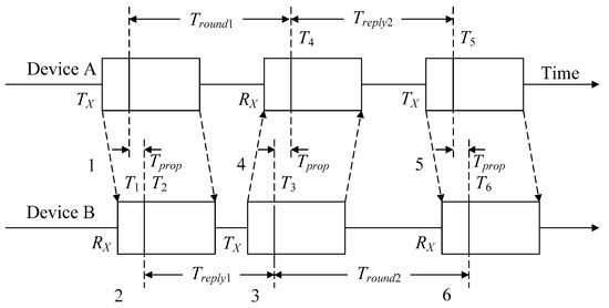
Figure 1.
UWB bilateral two-way ranging process.
- (1)
- Device A sends the polling data block, records the transmission time T1 and opens Rx after a period of time.
- (2)
- Device B should turn on reception in advance and then record the time T2 when the data block is polled.
- (3)
- After a transmission delay of Treply1, device B sends the response data block at T3 (T3 = T2 + Treply1) and then opens Rx.
- (4)
- Device A receives the response data block, and the recording time is T4.
- (5)
- After a transmission delay time of Treply2, device A sends the final polling data block at T5 (T5 = T4 + Treply2).
- (6)
- Device B receives the final polling data block and records the time at this time as T6.
According to the above process, the electromagnetic wave flight time Tprop is
The measuring distance is obtained by multiplying the electromagnetic wave typing time by the speed of light. The error always introduced by the DS ranging method is
where ka and kb are the ratios of the actual frequency and the expected frequency of the clock of device A and device B, respectively.
Although UWB can help to correct the drift of x and y coordinates, a single UWB receiver cannot provide reliable heading information. If you want to obtain vehicle heading information through UWB positioning information, you can use two UWB receivers to obtain vehicle yaw information through differential mapping. The course drift can be corrected by considering the influence of translation motion. If the vehicle is estimated to move forward for a short distance, the vehicle position and attitude can be estimated based on the incremental progress of x and y of the UWB receiver location information, as shown in Figure 2.
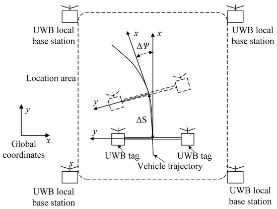
Figure 2.
Vehicle pose estimation by UWB.
Figure 2 shows the schematic diagram of UWB estimation of vehicle position and attitude. Specify a coordinate system on the vehicle. The origin is located between two UWB receivers. The x-axis points forward and the y-axis points to the left. With the incremental movement of the left UWB receiver and the right UWB receiver, the vehicle advances its coordinate system origin by a quantity and changes its advance by a quantity . If at time t, the location coordinates of the left and right UWB receivers are and , respectively, the updated UWB location coordinates at are and , respectively, and the incremental expression of the vehicle location coordinates and yaw is Equation (3):
In Equation (3), D is the distance between two UWB receivers. If the estimation of position and attitude is at time t, then the position and attitude of vehicle at time is Equation (4):
The estimation equation of vehicle speed and heading angular speed is (5)
3. Establishment of Experimental Equipment and Simulation Model
In order to test whether the algorithm is effective under two typical working conditions (i.e., meeting in a confined space and quarter turn), two vehicle driving routes are established for testing. One is a double lane change route, and the other is a quarter turn route. The ROS system can establish the algorithm for controlling the robot. After debugging the algorithm in the GAZEBO physical simulation environment in the ROS system, it can be directly transplanted to the physical system for testing, which can greatly improve the efficiency of algorithm testing. Therefore, the WLR-5A mining driverless wheeled chassis model is established in the ROS system, and the driving test is conducted according to the two planned routes. The location information of the UWB receiver is obtained by publishing the location topics of the left and right UWB receivers, and it is tested in the algorithm. During the simulation, the vehicle driving path was recorded, and then the algorithm was cloned to the WLR-5A industrial personal computer of the mining automatic driving chassis, and the algorithm was tested.
3.1. Experimental Test Vehicle Setup
As shown in Figure 3, the WLR-5A mining driverless wheel chassis is adopted and the whole vehicle is explosion-proof. The vehicle is composed of frame, front drive motor, front steering motor, rear drive motor, rear steering motor, main control box, slave control box, light box, etc. The vehicle is a four-wheel steering, four-wheel drive type, with dual rocker arm-independent suspension at the front and rear. The UWB used for the test is installed in the main control box and the distance between the left and right UWB receivers is D = 750 mm. The UWB receiver is connected with the on-board industrial computer, which is used for the processing of the above-received vehicle information data, and the processed data are shown visually on the display. See Table 1 for the technical parameters of the WLR-5A mining driverless wheeled chassis used in the algorithm.
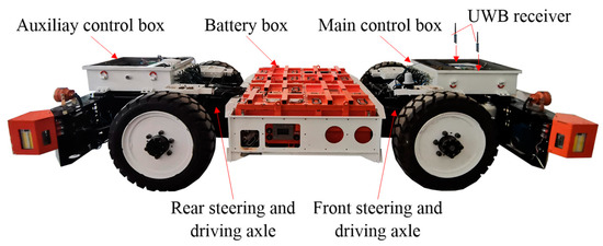
Figure 3.
Test vehicle assembly.

Table 1.
Technical parameters of WLR-5A mining wheeled unmanned chassis.
3.2. Establishment of Simulation Model
According to the technical parameters of the WLR-5A mining wheeled driverless chassis shown in Table 1, the whole vehicle model is established in ROS. Because the vehicle speed during the experiment is 5 m/s, the vehicle tires are solid tires, the suspension spring stiffness is large and the vehicle is unloaded. The vehicle is simplified as a rigid chassis in this study. The transmission mechanism and steering mechanism in the model are not modeled, and the four wheels are each controlled by the GAZEBO plug-in to achieve four-wheel steering and four-wheel drive in the model. The established model is loaded into the GAZEBO physical simulation environment, as shown in Figure 4. The components of the simplified simulation model and the connection mode between each component are shown in Figure 5. In this model, the battery box is set as base_ Link to perform coordinate transformation based on this component.
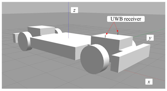
Figure 4.
Simulation model of WLR-5A.
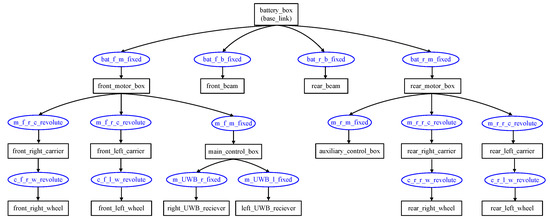
Figure 5.
Link and joints relationship of simulation model.
The topological relationship diagram of nodes and topics in the simulation process is shown in Figure 6, where /trajectory is the vehicle driving path publishing node, and the simulation path settings are defined in this node. This node releases corner position topics (/vehicle/Joint1,2,3,4_position_controller) to the four steering knuckles of the vehicle to achieve four-wheel steering. Speed topics are issued to four wheels (/vehicle/Joint5,6,7,8_velocity_controller) to achieve four-wheel drive. The steering and driving topics realize the simulation control of the vehicle in the GAZEBO environment through the GAZEBO plug-in. GAZEBO will publish the joint state topics (/joint_states) between the joint points of each component as well as publish the state topics (/GAZEBO/model_state) of the models in GAZEBO to pass to the gazebo_model_publisher, which will include the right_UWB_Receiver and left_UWB_receiver. The receiver’s position state is released by adding Gaussian noise to simulate UWB positioning information. After receiving the noisy UWB location information, the localizer performs noise reduction processing and location estimation to obtain the position and attitude information of the vehicle. The publisher node also publishes the vehicle attitude information topic (gazebo_vehicle_pose) to compare the accuracy of the location algorithm.
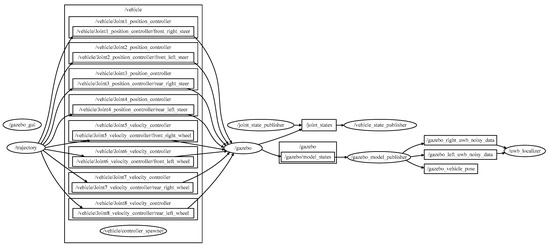
Figure 6.
The topological relationship diagram of nodes and topics.
3.3. Setup of Test and Simulation Environments
Considering that the main driving conditions of vehicles in the confined spaces of underground coal mines are two typical driving conditions, namely, meeting and quarter turning, in order to test the positioning of the algorithm under these two conditions, this study sets up a double lane shifting driving path and a quarter turning driving path to test the algorithm. In the test site, the test area is a simulated tunnel covered by UWB signals through which vehicles are traveling in this area. The coal-rock wall is the boundary which cannot allow the vehicle to intrude into the boundary during testing and simulation. At the same time, we assume that the signal cannot pass through the coal-rock wall in the coal mine, so we ensure that the vehicle can receive at least three signals from the base station at any position along the driving route to achieve positioning. Based on the above boundaries and assumptions, we have made the UWB base station layout scheme as shown in Figure 7 and Figure 8 for the test site.
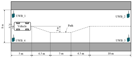
Figure 7.
Site of double lane shifting driving path.
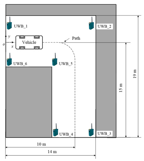
Figure 8.
Site of quarter turn path.
In the double lane shifting driving path shown in Figure 7, the length of the outer edge of the test site is 19 m and the width is 8 m. The vehicle driving path is shown by the dotted line in the figure. The location of the global coordinate system is shown in Figure 7. The UWB base station is located at four corners of the outer edge of the road. The location of the UWB base stations are UWB_ 1 (0 m, 4 m),UWB_ 2 (29 m, 4 m),UWB_ 3 (29 m, −4 m) and UWB_ 4 (0 m, −4 m).
In the quarter turn driving path shown in Figure 8, the outer edge of the test site is 19 m long and 14 m wide and the road width is 8 m. The vehicle driving path is shown by the dotted line in the figure and the vehicle turning radius is 3 m. The global coordinate location system is shown in Figure 8. The UWB base stations are located at four corners on the outer edge of the road. The positions of the UWB base stations are, respectively, UWB_ 1 (0 m, 4 m), UWB_ 2 (14 m, 4 m), UWB_ 3 (14 m, −15 m), UWB_ 4 (6 m, −15 m), UWB_ 5 (6 m, −4 m) and UWB_ 6 (0 m, −4 m).
4. Results and Discussion
Taking the WLR-5A mining wheeled driverless chassis controlled by a CAN bus as the test platform, the ground test site with fixed routes and arranged UWB base stations as the test environment, the GAZEBO physical simulation environment in the robot operating system as the simulation platform and the two typical driving paths of quarter turn and double lane shift as the test conditions, the algorithm is tested through the combination of simulation and experiment, and the vehicle position and attitude estimation test results are obtained, At the same time, the error of the test results is analyzed.
4.1. Results of Double Lane Shifting
Figure 9 shows the experimental and simulation results of the position and attitude estimation of the double lane shifting driving path. Figure 9a shows the experimental and simulation results curve of the x-direction position estimation of the double lane shifting driving path. In Figure 9a, the vehicle is stationary for 0–5 s and continues to move forward after 5 s. The x-direction position estimation value increases with time. The position estimation curve obtained in the experiment has some noise, but the experimental test data are consistent with the real data points in the experiment process. The position estimation result in the simulation basically coincides with the real result curve. Figure 9b shows the experimental and simulation results curve of the y-direction position estimation of the double lane shifting driving path. The vehicle is stationary for 0–5 s and continues to move forward for 5–8 s. The y-direction position estimation value is 0. When the vehicle runs for 8 s, 14 s, 19 s and 24 s, the vehicle starts to turn and the y-direction position estimation value changes. After 24 s, the vehicle returns to the original driving lane and the y-direction position estimation value is 0. In Figure 9b, the estimated curve of the vehicle position in the y direction in the simulation process is consistent with the real curve. However, the position estimation curve in the experiment has some noise, and the real vehicle position data points have some fluctuations during the experiment, but their trends are basically consistent. Figure 9c shows the experiment and simulation results of the vehicle yaw in the double lane changing driving path. Compared with the estimated yaw and the real yaw in the experiment in Figure 9c, the vehicle is stationary for 0–5 s and continues to move forward for 5–8 s. The estimated yaw is 0. The vehicle turns in 0–14 s, the yaw changes from 0 to −0.4 rad and then changes to 0 rad. After entering another lane and driving for 14–19 s, the yaw is 0 rad. In 19–24 s, the vehicle moves to the original lane line and the yaw changes from 0 to 0.4 rad and then from 0.4 rad to 0 rad. After 24 s, the vehicle will drive in the original lane with a yaw of 0 rad. We can find from the course angle estimation and the true course angle curve in the simulation that the estimated value of the course angle is consistent with the true value curve of the course angle. Although there is noise in the estimated value of the course angle in the experiment, the course angle curve can still reflect the change rule of the course angle during the vehicle’s traveling.
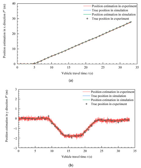
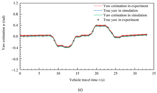
Figure 9.
Position and attitude estimation of double lane shifting driving path. (a) Position estimation in x direction. (b) Position estimation in y direction. (c) Yaw estimation.
The experimental and simulation results of the double lane shifting driving path and vehicle position and attitude estimation shown in Figure 9 demonstrate that the vehicle position estimation method proposed in this study is consistent with the real vehicle position estimation in the estimation of vehicle driving direction, side direction and yaw. Although there is some noise in the process of the experiment, the results of the vehicle position and attitude estimation can still reflect the changes of the x- and y-directions and yaw in the process of the vehicle moving.
Figure 10 shows the error between the experimental and simulation results of the position and attitude estimation of the double lane shifting driving path. Figure 10a shows the position estimation error in the x-direction. The vehicle is at a standstill in 0–5 s and the error of the position estimation results of the experiment and simulation is 0%. When the vehicle starts to run, the vehicle position estimation error during the experiment increases to 0.0046%, which is due to the impact of vehicle jitter on vehicle positioning during vehicle startup. When the vehicle runs smoothly, the position estimation error decreases and tends to be stable. In the simulation process, the vehicle is in an ideal environment and its position estimation error is basically 0%. During the experiment, the estimated error of the vehicle position in the x direction is within 0.005%. Figure 10b shows the position estimation error in the y-direction. The vehicle is at a standstill in 0–5 s and the error of the position estimation results of the experiment and simulation is 0%. When the vehicle starts to run, the vehicle position estimation error during the experiment increases to 0.08%. In the simulation process, the vehicle is in an ideal environment and its position estimation error is basically 0%. During the experiment, the estimated error of the vehicle position in the y-direction is within ±0.4%.
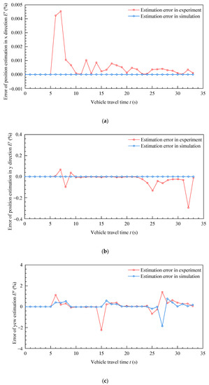
Figure 10.
Position and attitude estimation error of double lane shifting driving path. (a) Position estimation error in x direction. (b) Position estimation error in y direction. (c) Yaw estimation error.
Figure 10c shows the estimation error of vehicle yaw. The vehicle is at a standstill in 0–5 s and the error of the estimated yaw of the experiment and simulation is 0%. When the vehicle starts to run, the heading error of the vehicle is large in 5–10 s, 14–20 s and 29–30 s. This is because the algorithm has a large yaw estimation error due to the vehicle’s swinging while turning. In particular, the estimated yaw error in the experiment is larger than that in the simulation environment due to certain noise in the UWB. However, the estimated error of the yaw obtained from the experiment and simulation is within ±2%.
The error analysis of the experimental and simulation results of the double lane shifting driving path and vehicle position and attitude estimation shown in Figure 10 demonstrates that the vehicle position estimation method proposed in this study has a certain deviation from the real position of the vehicle in the estimation of the vehicle’s driving direction, side direction and yaw. In particular, the estimation deviation of the vehicle’s yaw is large, but the error during the stable operation of the vehicle is basically 0%. Based on the comprehensive error analysis results, it can be concluded that the estimation errors of the vehicle position and attitude are within ±2% in the double lane shifting driving route.
4.2. Results of Quarter Turn
Figure 11 shows the experimental and simulation results of the pose estimation of the quarter turn driving path. Figure 11a shows the curve of the experimental and simulation results of the position estimation in the x-direction. In Figure 11a, the vehicle is stationary in 0–12 s. At this time, the estimated value of the position in the x-direction is 0 and the estimated value of the position in the x-direction increases in 12–20 s. The estimated value of the position in the x-direction increases slowly in 20–25 s. After 25 s, the vehicle turns completely and the estimated value of the position in the x-direction does not change to 10 m. There is some noise in the position estimation curve obtained from the vehicle experiment, but the experimental test data are consistent with the real data points in the experiment process. The position estimation result in the simulation basically coincides with the real result curve. Figure 11b shows the curve of the experimental and simulation results of the position estimation in the y-direction. As shown in Figure 11b, the vehicle is stationary in 0–12 s. At this time, the estimated value of the position in the y-direction is 0 and the estimated value of the position in the y-direction increases after 12–20 s. The estimated value of the position in the y-direction increases slowly after 20–25 s when the vehicle turns. After 25 s, the vehicle turns completely, and the driving direction of the vehicle turns from the x-direction to the negative direction of y, and the estimated value of the position in the y-direction continues to increase. The position estimation curve obtained in the experiment has some noise, but the experimental test data are consistent with the real data points in the experiment process. The position estimation result in the simulation basically coincides with the real result curve. The change of yaw during quarter turning is shown in Figure 11c. The yaw is basically 0 during 0–20 s when the vehicle is stationary and driving along the straight line in the x-direction. During the 20–25 s period, the vehicle turns clockwise around the z-axis and the yaw changes from 0 rad to −1.53 rad. After 25 s, the vehicle enters the straight-line driving state, and the yaw remains unchanged. By comparing the estimated yaw and the true yaw in the experiment in Figure 11c, we can find that the estimated yaw and the true yaw curve in the simulation are consistent. Although there is noise in the estimated yaw in the experiment, the yaw curve can still reflect the rule change of the yaw during the vehicle’s travel.
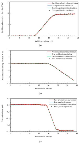
Figure 11.
Position and attitude estimation of quarter turn path. (a) Position estimation in x direction. (b) Position estimation in y direction. (c) Yaw estimation.
Figure 12 shows the error between the experimental and simulation results of the pose estimation of the quarter turn driving path. Figure 12a shows the position estimation error in the x-direction. The vehicle is at a standstill in 0–5 s, and the error of the position estimation results of the experiment and simulation is 0%. When the vehicle starts to run for 5–10 s, the vehicle position estimation error during the experiment increases to 1.8%, which is due to the impact of vehicle jitter on the vehicle positioning during vehicle starting. When the vehicle runs smoothly, the position estimation error decreases and tends to be stable, and the position estimation error is less than 0.4%. In the simulation process, the vehicle is in an ideal environment and its position estimation error is basically 0%. During the experiment, the error of the vehicle position estimation in the x-direction is less than 1.8%.
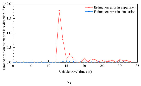
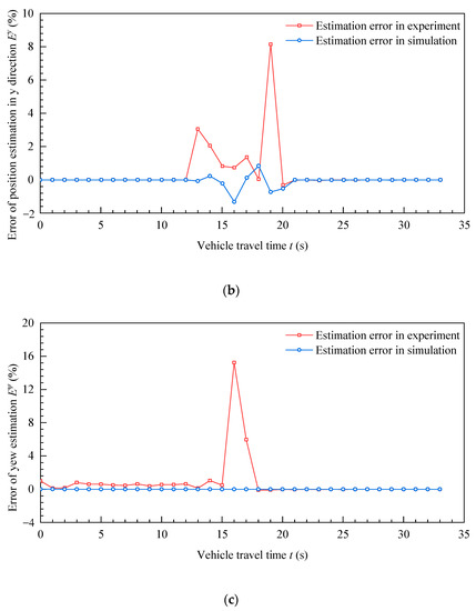
Figure 12.
Position and attitude estimation error of quarter turn path. (a) Position estimation error in x direction. (b) Position estimation error in y direction. (c) Yaw estimation error.
Figure 12b shows the position estimation error in the y-direction. The vehicle is at a standstill in 0–5 s and the error of the position estimation results of the experiment and simulation is 0%. When the vehicle starts to run, the vehicle position estimation error during the experiment increases to 2.8%. When the vehicle turns for 15–20 s, the position error in the y-direction fluctuates greatly, up to 8.2%. In the simulation process, the vehicle is in an ideal environment and its position estimation error is within ±1.8%. Figure 12c shows the estimation error of the vehicle yaw. When the vehicle is stationary for 0–5 s and runs along the x-direction in a straight line for 5–15 s, the error of the simulated goniometer results is 0%, and the error of the yaw obtained from the experiment fluctuates within the range of 0–0.8%. When the vehicle turns, the yaw error increases to 16%. This is because there is a significant error due to the influence of the vehicle’s swinging in the course of calculating the yaw when the vehicle turns. However, after the vehicle is stabilized, the yaw error rapidly decreases to 0.
The error analysis of the experiment and simulation results of the quarter turn driving path and vehicle position and attitude estimation shown in Figure 12 shows that the vehicle position estimation method proposed in this study has a certain deviation from the real position of the vehicle in the estimation of the vehicle’s driving direction, side direction and yaw. Especially in the process of turning, the estimation deviation of the vehicle’s yaw is large, but the error in the process of stable vehicle operation is basically 0%. The real-time requirements for the positioning of underground vehicles in coal mines are relatively low, and the use of the positioning information of underground vehicles in coal mines will not be affected if the short-term error during turning is too large. The comprehensive error analysis results can be concluded to show that the estimation error of vehicle position and attitude on the quarter turn driving route basically meets the requirements of coal mine underground use.
5. Conclusions
In this study, according to the principle of UWB positioning, the positioning information of the UWB sensor is introduced to infer the position and yaw of underground vehicles through a differential mapping algorithm in the underground GPS free positioning environment. Taking a WLR-5A mining wheeled driverless chassis as the experimental test platform, the UWB base station is installed on the ground and the test path is specified. Taking the GAZEBO physical simulation environment in the robot operating system as the simulation platform, the effectiveness of the position and attitude estimation method of double lane shifting and quarter turning is tested through the combination of simulation and experiment. The main conclusions are as follows:
- Aiming at the problem that the underground GPS signal cannot be located, this research adopts the differential mapping method of dual UWB locators to estimate the position and attitude of underground vehicles. The algorithm results of double lane change and quarter turn show that the estimation of vehicle direction, side direction and yaw is consistent with the estimation of the vehicle’s real position. The result curve can reflect the change rule of x- and y-directions and yaw during vehicle traveling.
- In the position estimation error of double lane shifting and quarter turning conditions, there is a certain deviation between the vehicle driving direction and lateral position estimation and the real position of the vehicle. The maximum deviation is 8.2%, but the error during the stable operation of the vehicle is basically 2%. The comprehensive error analysis results can be considered to show that the vehicle position and attitude estimation results of the algorithm proposed in this study basically meet the requirements of underground coal mines.
- In the course angle estimation error of double lane shifting and quarter turning conditions, there is a certain deviation from the true course angle of the vehicle, especially in the course of turning. The estimated deviation of the vehicle course angle is large, reaching 16%, but the error in the process of stable operation of the vehicle is basically 2% under the conditions of low real-time requirements for underground vehicle positioning in coal mines. The algorithm proposed in this study can basically meet the requirements of underground coal mines for estimating the vehicle yaw.
Author Contributions
Conceptualization, Y.B.; Formal analysis, X.Y., M.H. and Z.L.; Funding acquisition, Q.J.; Investigation, Q.J. and J.B.; Methodology, Y.B.; Project administration, Q.J.; Resources, X.Y. and Z.L.; Software, X.Y. and M.H.; Supervision, J.B.; Visualization, M.H.; Writing—original draft, Y.B.; Writing—review & editing, Z.L. and J.B. All authors have read and agreed to the published version of the manuscript.
Funding
This research was financially supported by the National Key R&D Program of China (2020YFB1314003) and general projects of enterprises (grant number F2022-MS03). The APC was funded by F2022-MS03.
Data Availability Statement
Not applicable.
Acknowledgments
The authors wish to thank the editor and reviewers.
Conflicts of Interest
The authors declare that there are no conflicts of interest regarding the publication of this paper.
References
- Bouvet; Garcia, G. Improving the accuracy of dynamic localization systems using RTK GPS by identifying the GPS latency. In Proceedings of the IEEE International Conference on Robotics, San Francisco, CA, USA, 24–28 April 2000; pp. 2525–2530. [Google Scholar]
- Panzieri, S.; Pascucci, F.; Ulivi, G. An outdoor navigation system using GPS and inertial platform. Trans. Mechatron. 2002, 7, 134–142. [Google Scholar] [CrossRef]
- Szrek, J.; Trybała, P.; Góralczyk, M.; Michalak, A.; Ziętek, B.; Zimroz, R. Accuracy Evaluation of Selected Mobile Inspection Robot Localization Techniques in a GNSS-Denied Environment. Sensors 2021, 21, 141. [Google Scholar] [CrossRef] [PubMed]
- Bewley, A.; Upcroft, B. Background appearance modeling with applications to visual object detection in an open-pit mine. J. Field Robot. 2017, 34, 53–73. [Google Scholar] [CrossRef]
- Kanellakis, C.; Nikolakopoulos, G. Evaluation of visual localization systems in underground mining. In Proceedings of the 2016 24th Mediterranean Conference on Control and Automation (MED), Athens, Greece, 21–24 June 2016; pp. 539–544. [Google Scholar]
- Ćwian, K.; Nowicki, M.R.; Wietrzykowski, J.; Skrzypczyński, P. Large-Scale LiDAR SLAM with Factor Graph Optimization on High-Level Geometric Features. Sensors 2021, 21, 3445. [Google Scholar] [CrossRef] [PubMed]
- Li, M.; Zhu, H.; You, S.; Tang, C.; Li, Y. Efficient Laser-Based 3D SLAM in Real Time for Coal Mine Rescue Robots. In Proceedings of the IEEE 8th Annual International Conference on CYBER Technology in Automation, Control and Intelligent Systems, Tianjin, China, 19–23 July 2018; pp. 971–976. [Google Scholar]
- Menggang, L.; Hua, Z.; Shaoze, Y.; Lei, W.; Chaoquan, T. Efficient laser-based 3D SLAM for coal mine rescue robots. IEEE Access. 2019, 7, 14124–14138. [Google Scholar]
- Lin, P.; Li, Q.; Fan, Q.; Gao, X.; Hu, S. A real-time location based services system using WiFi fingerprinting algorithm for safety risk assessment of workers in tunnels. Math. Probl. Eng. 2014, 2014, 1–10. [Google Scholar] [CrossRef]
- Cypriani, M.; Delisle, G.; Hakem, N. Wi-Fi-based positioning in underground mine tunnels. In Proceedings of the International Conference on Indoor Positioning and Indoor Navigation, Montbeliard, France, 28–31 October 2013; pp. 1–7. [Google Scholar]
- Guo, Y.; Liu, H.; Shu, L.; Li, J. The precise underground localization method based on WiFi network. In Proceedings of the 18th Asia–Pacific Conference Community, Oita, Japan, 6–9 September 2012; pp. 664–667. [Google Scholar]
- Park, S.; Choi, Y. Analysis and Diagnosis of Truck Transport Routes in Underground Mines Using Transport Time Data Collected through Bluetooth Beacons and Tablet Computers. Appl. Sci. 2021, 11, 4525. [Google Scholar] [CrossRef]
- Chehri, A.; Saadane, R. Zigbee-based remote environmental monitoring for smart industrial mining. In Proceedings of the SCA2019: The Fourth International Conference on Smart City Applications, Casablanca, Morocco, 2–4 October 2019; pp. 2–7. [Google Scholar]
- Moridi, M.A.; Kawamura, Y.; Sharifzadeh, M.; Chanda, E.K.; Jang, H. An investigation of underground monitoring and communication system based on radio waves attenuation using ZigBee. Tunn. Undergr. Space. Technol. 2014, 43, 362–369. [Google Scholar] [CrossRef]
- Longkang, W.; Baisheng, N.; Ruming, Z. ZigBee-based positioning system for coal miners. Proc. Eng. 2011, 26, 2406–2414. [Google Scholar] [CrossRef]
- Liu, Z.; Li, C.; Wu, D. A wireless sensor network based personnel positioning scheme in coal mines with blind areas. Sensors 2010, 10, 9891–9918. [Google Scholar] [CrossRef] [PubMed]
- Rusu, S.R.; Hayes, M.J.D.; Marshall, J.A. Localization in largescale underground environments with RFID. In Proceedings of the 24th Canadian Conference on Electrical and Computer Engineering (CCECE), Niagara Falls, ON, Canada, 8–11 May 2011; pp. 1140–1143. [Google Scholar]
- Chehri, A.; Fortier, P.; Tardif, P.M. UWB-based sensor networks for localization in mining environments. Ad Hoc Netw. 2009, 7, 987–1000. [Google Scholar] [CrossRef]
- Zhao, W.D.; Goudar, A.; Schoellig, A.P. Finding the Right Place: Sensor Placement for UWB Time Difference of Arrival Localization in Cluttered Indoor Environments. IEEE Robot. Autom. Lett. 2022, 7, 6075–6082. [Google Scholar] [CrossRef]
- Qin, Y.Q.; Wang, F.; Zhou, C. A distributed UWB-based localization system in underground mines. J. Netw. 2015, 10, 134–140. [Google Scholar] [CrossRef]
- Yang, H.; Luo, T.; Li, W.; Li, L.; Rao, Y.; Luo, C.M. A stable SINS/UWB integrated positioning method of shearer based on the multi-model intelligent switching algorithm. IEEE Access. 2019, 7, 29128–29138. [Google Scholar] [CrossRef]
- Wu, D.; Meng, Y.; Gu, Q.; Ma, F.; Zhan, K. A novel method for estimating the yaw for underground Load-Haul-Dump based on Ultra Wideband. Trans. Inst. Meas. Control 2017, 40, 1608–1614. [Google Scholar] [CrossRef]
- Li, M.; Zhu, H.; You, S.; Tang, C. UWB-based localization system aided with inertial sensor for underground coal mine applications. IEEE Sens. J. 2020, 20, 6652–6669. [Google Scholar] [CrossRef]
- Zhang, K.Y.; Chen, P.P.; Ma, T.B.; Gao, S.W. On-Demand Precise Tracking for Energy-Constrained UAVs in Underground Coal Mines. IEEE Trans. Instrum. Meas. 2022, 71, 5500814. [Google Scholar] [CrossRef]
- Alonge, F.; Cusumano, P.; D’Ippolito, F.; Garraffa, G.; Livreri, P.; Sferlazza, A. Localization in Structured Environments with UWB Devices without Acceleration Measurements and Velocity Estimation Using a Kalman–Bucy Filter. Sensors 2022, 22, 6308. [Google Scholar] [CrossRef] [PubMed]
- Cheng, G.L. Accurate TOA-based UWB localization system in coal mine based on WSN. Phys. Proc. 2012, 24, 534–540. [Google Scholar] [CrossRef]


Publisher’s Note: MDPI stays neutral with regard to jurisdictional claims in published maps and institutional affiliations. |
© 2022 by the authors. Licensee MDPI, Basel, Switzerland. This article is an open access article distributed under the terms and conditions of the Creative Commons Attribution (CC BY) license (https://creativecommons.org/licenses/by/4.0/).