Article

Potential of CO2 Emission Reduction via Application of Geothermal Heat Exchanger and Passive Cooling in Residential Sector under Polish Climatic Conditions

by
Natalia Fidorów-Kaprawy
* and
Łukasz Stefaniak
*
Faculty of Environmental Engineering, Wrocław University of Science and Technology, 50377 Wrocław, Poland
*
Authors to whom correspondence should be addressed.
Energies 2022, 15(22), 8531; https://doi.org/10.3390/en15228531
Submission received: 27 October 2022 / Revised: 10 November 2022 / Accepted: 12 November 2022 / Published: 15 November 2022

Abstract

:
The article summarizes the results of the 25-year time horizon performance analysis of the ground source heat pump that serves as a heat source in a detached house in the climatic conditions that prevail in Wrocław, Poland. The main aim is to assess the potential of ground regeneration and reduction of CO2 emission by passive cooling application. The study adds value to similar research conducted worldwide for various conditions. The behavior of the lower source of the heat pump was simulated using EED software. The ground and borehole properties, heat pump characteristics, heating and cooling load, as well as the energy demand for domestic hot water preparation have been used as input data. Based on the brine temperatures for all analyzed cases including the ground with lower and higher values of conductivity and heat capacity, the borehole filler of inferior and superior thermal properties, and the passive cooling option turned on and off, the seasonal efficiencies of the heat pump have been calculated. The energy and emission savings calculations are based on the values obtained. The application of passive cooling reduces the brine temperature drop by 0.5 K to over 1.0 K in consecutive years in the analyzed cases and the thermal imbalance by 65.0% to 65.9%. Electric energy savings for heating and domestic hot water preparation reach 4.5%, but the greatest advantage of the system is the possibility of almost emission-free colling the living spaces which allows reducing around 33.7 GWh of electric energy and 1186–1830 kg of CO2 emission for cooling.

1. Introduction

Along with the increasing demand for cooling worldwide [1,2], more and more residential, public, and commercial spaces are equipped with cooling or air conditioning systems [3]. Electricity used for cooling purposes accounts for approximately 20% of the energy use of buildings [1]. Switching from mechanical devices with refrigerants of high global warming potential (GWP) or assessed by life cycle climate performance (LCCP) as a more holistic indicator [4] to more efficient and non-polluting systems can save up to 210–460 Gt of CO2 equivalent (GtCO2e) over the next 40 years [5]. As stress is put on the decarbonization idea, researchers examine, develop, and implement innovative solutions based on renewable resources. The application of ground source heat pumps (GSHPs) is consistent with both decarbonization and low energy consumption [6,7].
It is well known that GSHPs may use the ground as a heat source or a heat sink depending on the operating mode and the heating/cooling demand of the building. The ground provides less fluctuations in the source temperature throughout the year and remains stable (10 °C) around 15 m below the surface [8]. It results in increased efficiency compared to air source heat pumps (ASHPs) followed by reduction of CO2 emissions [9].
However, energy extraction during periods with high heating demand can cause borehole overcooling or even freezing over years of operation and cause a significant reduction in efficiency [10]. Szulgowska-Zgrzywa and Fidorów-Kaprawy in their paper [11] provided the study of the brine-to-water heat pump system in an office building. The research resulted in 0.8 K cool down in the borehole temperature for the system without regeneration. Rubinova et al. [12] provided data for a detached house with a result of a temperature drop of 3.2 K in an almost 2-year cycle and thus evidence of a decrease in the performance of a non-regenerated GSHP system. A solution that prevents the borehole overcooling process is to transfer thermal energy through the borehole piping. This process is called active ground regeneration. Various methods and ground regeneration configurations are investigated. Solar technologies and thermal collectors, as well as photovoltaic panels as GSHP regeneration systems, were analyzed for the South European climate by Reda et al. [13]. Reda and Laitinen [14] also investigated the application of solar energy to recharge boreholes in a cold North European climate. However, Miglani et al. [15] revealed that even solar thermal collectors used to regenerate a lower source of GSHP were able to increase the ground temperature above the initial, but still it was only a short-term effect. Over a 20-year operation time, the decrease in ground temperature was 7.7 K for a system with ground regeneration and 10.7 K without regeneration. Besides solar technologies, hybrid systems are also being investigated. The GSHP system with an air-to-glycol heat exchanger in the supply air duct was investigated by Radomski et al. [16]. The heat exchanger was recovering heat from the supply air during summer and transferring it to the ground, while in winter it was heating preliminary air in order to prevent the recuperator from freezing. Research shows an increase in energy effectiveness of 31.8%, which results in a reduction of 306.4 kg of CO2 emissions in one year. A more advanced hybrid system with the addition of both solar panels and cooling tower working with GSHP for an office building has been investigated in Japan [17]. The case provides data for full ground regeneration by use of solar panels and the COP increase by 0.72 for cooling tower implementation. Allaerts et al. [18] presented evidence for the positive influence of the passive cooling system combined with GSHP for a school building in Belgium. The regeneration of the ground with passive cooling improved the COP from 4.5 to 4.8 and the thermal imbalance decreased from 90.9% to 23.1% after 15 years.
By implementing ground regeneration, underground material itself becomes a part of the Underground Thermal Energy Storage (UTES) system. More precisely, material (rock, soil, etc.) around boreholes stores thermal energy. Such a system is one of the UTES types: Borehole Thermal Energy Storage (BTES) [19]. GSHP in tandem with UTES provides ground regeneration in a one-year cycle (Figure 1). During the cold season, the extraction of heat decreases the temperature of boreholes and the surrounding ground [20,21]. During the warm season, the waste heat is extracted from the building and transferred to boreholes and the ground. The ground temperature is therefore increased even up to before the cold season state. However, it is important to balance loads so that the ground is neither overcooled nor overheated [22,23]. Another aspect of proper ground heat exchanger work is the design [24]. Researchers provide various configurations of boreholes analyses [25,26,27] that ensure efficient use of energy stored in the ground. Analyses are followed by methods to calculate and forecast ground response over the years of heat extraction or rejection [28,29]. Proper design, based on available literature, can improve the balance of supply and energy extraction [30,31]. It also helps to avoid short-circuiting between pipes in U-pipe heat exchangers due to correct spacing between boreholes [32].
Cooling is mainly considered as decreasing the indoor air temperature when the outdoor temperature is high. In terms of thermal comfort during the warm season, one must consider not only the indoor air temperature, but most importantly the mean radiant temperature [33,34,35]. Due to differences in building material, exposure to solar radiation, and floor level [36], both indoor air temperature and mean radiant temperature are influenced. However, it has been shown [37] that the mean radiant temperature is higher than the indoor air temperature. Therefore, radiant cooling becomes increasingly desired [34,38]. In the process of radiant cooling, the temperature of building envelope’s is decreased, and it behaves as a radiant cooling surface. Low-temperature surfaces are able to generate a feeling of coolness despite the relatively high indoor air temperature [15]. The correlation between the increase in the indoor air temperature and the decrease in mean radiant temperature has been calculated, while maintaining the same level of thermal comfort—a decrease of 0.77 °C (1.39 °F) in mean radiant temperature can be compensated by an increase of 0.55 °C (1.00 °F) in air temperature [39]. It is consistent with the nature of a human body that uses convective and radiative heat transfer influenced by indoor air temperature and mean radiant temperature [40]. Human body values of radiative heat transfer (4.5 W/m2 K) and convective heat transfer (3.4 W/m2 K) differ significantly [41]. More than 30% of heat can be transferred from the human body to the surrounding by radiation. Thus, radiant mean temperature should be taken into account even more than indoor air temperature while considering thermal comfort of occupants.
Radiant cooling can be easily combined with sources that supply relatively high-temperature cooling agents (15–19 °C) [42,43,44], such as in the case of GSHPs with passive cooling systems. Despite the low temperature values difference between indoor air and the cooling agent, GSHPs with surface cooling/heating systems utilize cooling energy in an efficient way due to the significant heat transfer surface and radiation. GSHPs can be equipped with passive cooling systems that contain only a heat exchanger, mixing valve, and circulation pumps (for brine and cooling system). They do not require a compressor to operate and transfer excess heat from the building to the ground. The passive cooling process, by rejecting heat to the ground, contributes to energy savings and maintains more stable ground temperatures over years [11,18].
It becomes visible that, on the one hand, there is a tendency to increase the thermal comfort in buildings by equipping them with advanced heating and cooling systems, and on the other hand, as mentioned before, the great stress is put on improving the efficiency of buildings and systems as well as lowering the CO2 footprint of the built environment. Cooling technologies with low CO2 emissions are needed because traditional technologies are considered to be too polluting [45]. Passive radiant cooling systems powered by GSHP boreholes are promising for two reasons: they may regenerate lower energy sources (improving heat pump performance) [11,16,18] and remove excess heat from rooms creating a comfortable environment [45,46]. Thus, research and analysis concerning those two aspects are being conducted worldwide, assessing the performance of such systems under different climatic conditions.
The aim of this paper is to analyze the performance of a system powered by a brine-to-water heat pump with and without passive cooling for different soil types and borehole fillings in a 25-year time horizon. The analysis estimated two ways in which the reduction of CO2 emissions was achieved through the use of passive cooling under the climatic conditions of Poland. Firstly, is the possibility of providing a sufficient amount of cooling energy throughout the year without any additional cooling systems that might contribute to increase CO2 equivalent emissions (connected to the use of refrigerants) [47]. Secondly, is by ground regeneration that improves the SCOP of the system and thus decreases the amount of electric energy as more thermal energy is extracted from the lower heat source. The article adds value to the research concerning the reduction of CO2 emission in the residential sector with the simultaneous improvement of thermal comfort carried out worldwide.

2. Materials and Methods

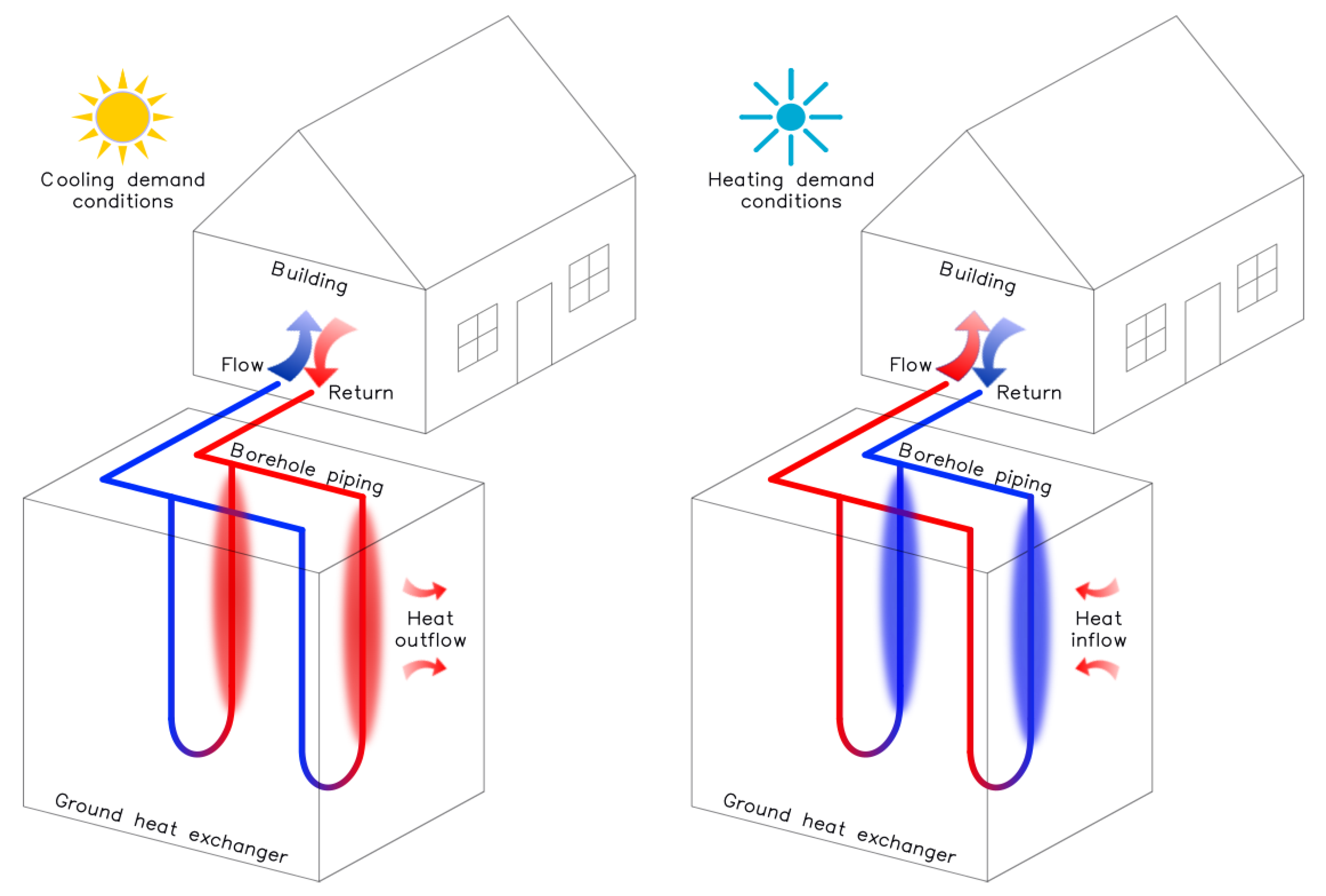
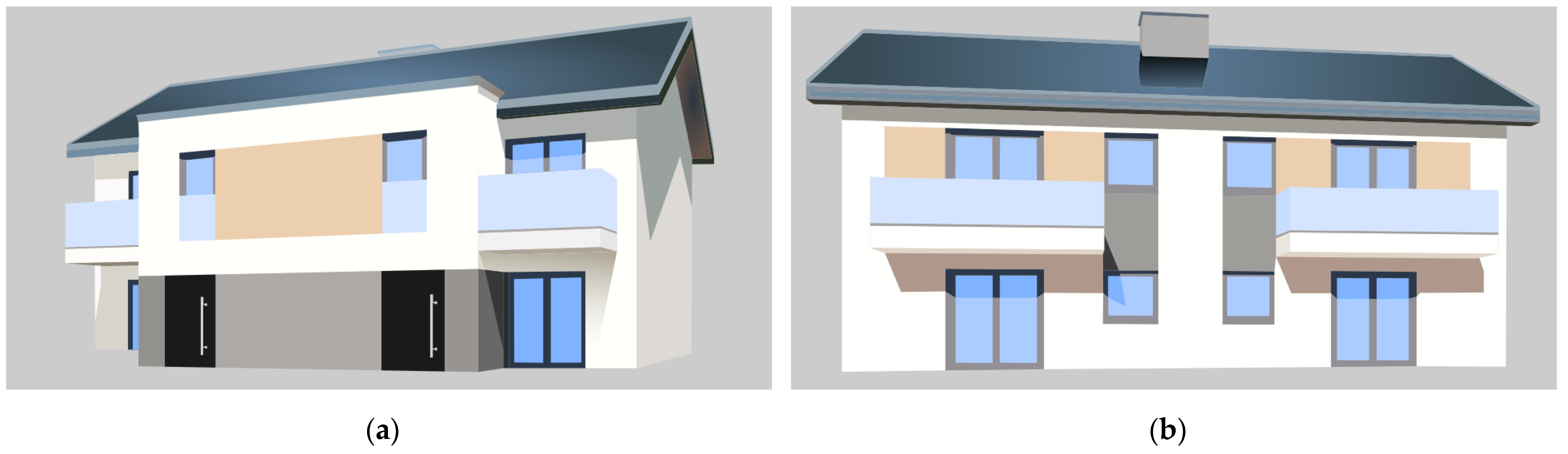
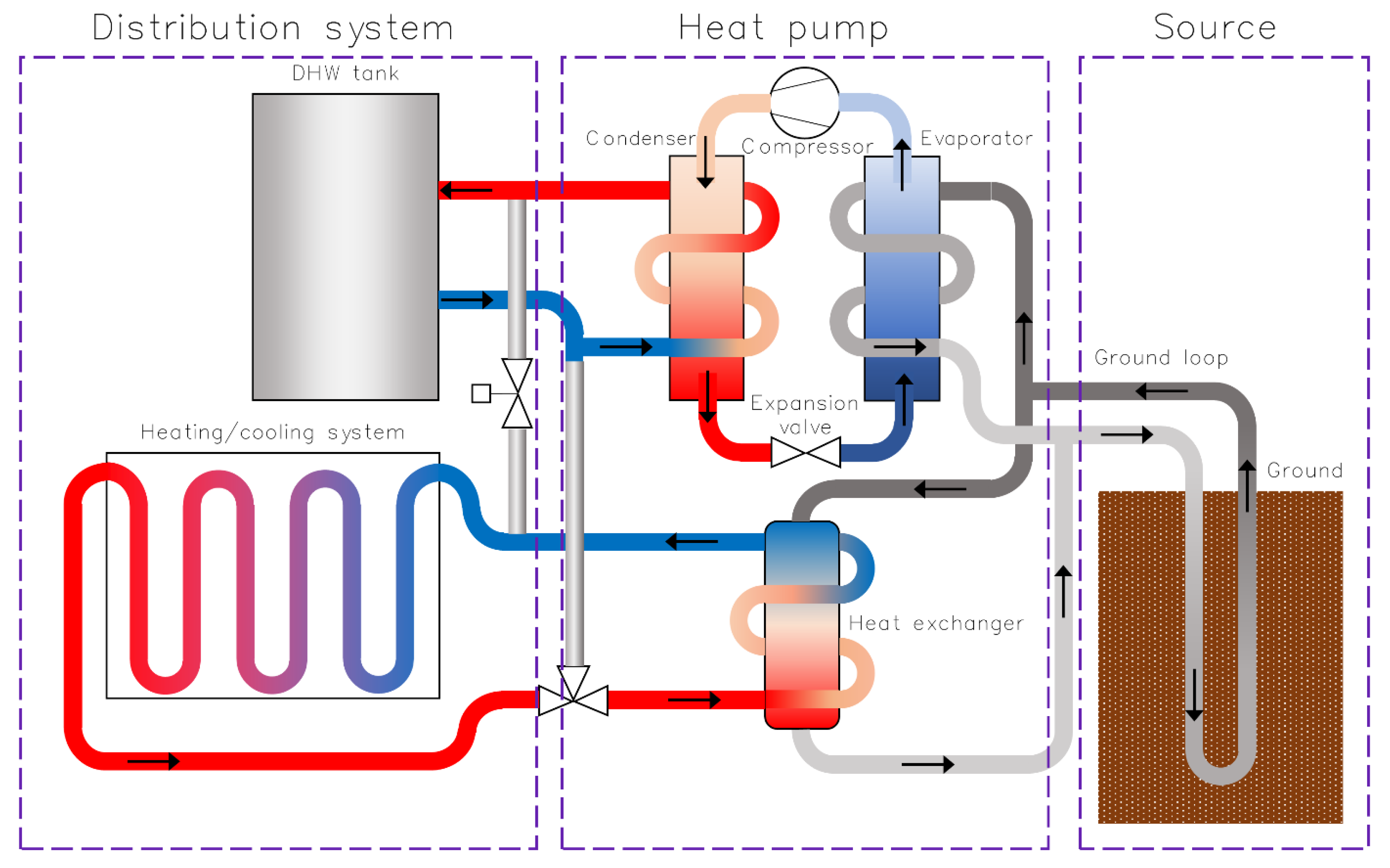
2.1. The Installation and the Building

In this paper, the authors describe the energy analysis including the influence of passive cooling on the GSHP performance as well as the possibility of achieving a sufficient level of cooling with this system in a two-family detached house in Polish climatic conditions (temperate warm transitional climate). The building is shown in Figure 2. The UTES behavior was simulated using EED software (tool that proved its usefulness for such purposes [48,49]) taking into account various assumptions that can affect both the efficiency of the heat pump as well as the regeneration of the ground. The specification of the investigated multifamily, residential, heated, and cooled building is shown in Table 1.
The system is equipped with GSHP Vitocal 300-G BW 301.B06 type with passive cooling pack NC-box. Nominal thermal power (B0/W35) is equal to 5.7 kW and COP 4.43. The heat source consists of two 77 m deep boreholes each with a specification given in Table 2.
The system provides energy for heating and domestic hot water (DHW) preparation as well as serves as a cooling device for the specified residential building. During the warm season, the ground serves as the heat source for the DHW and sink for cooling purposes. DHW preparation is realized with standard compressor operation. Passive cooling operates only with the heat exchanger. A scheme of the system is shown in Figure 3.
For the purposes of analysis, heating and cooling loads were calculated in Purmo OZC basic 6.7 software. DHW demand was calculated according to DIN 4708-2 (recommended by the heat pump producer). The values obtained are given in Figure 4.

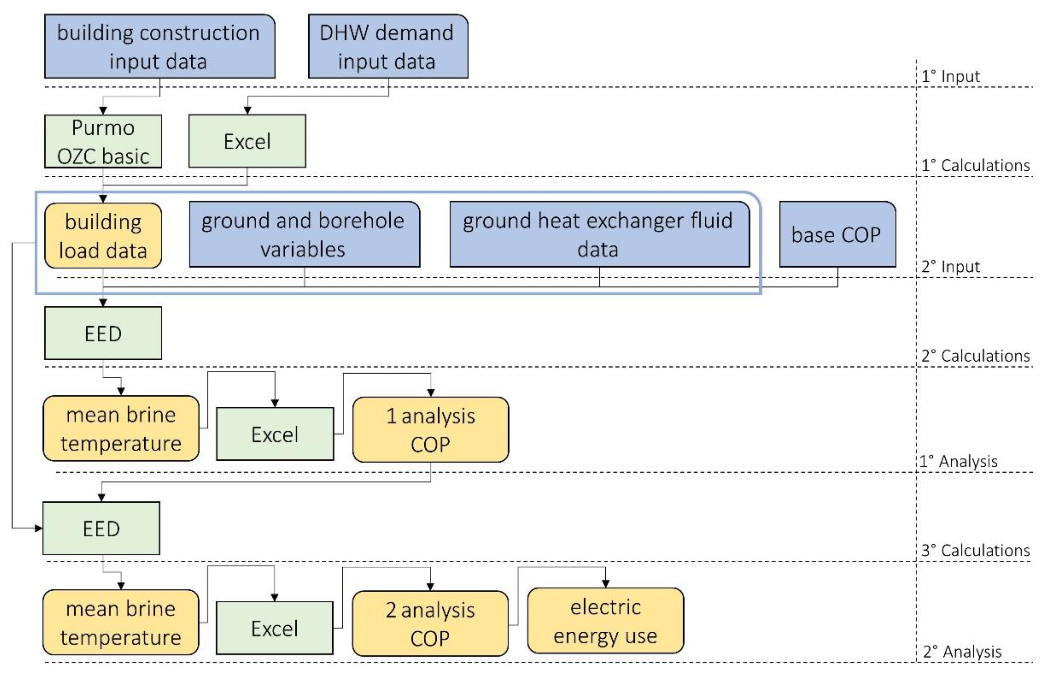
2.2. Simulations and Calculations

The purpose of the simulations was to calculate the mean temperature of the brine in the system at the end of each month in the next 25 years. Simulations were performed using Earth Energy Designer 3.22 software. The investigation was extended by implementing variable ground and borehole properties (Table 3); therefore, the results are more universal. Both the ground and the borehole are presented as versions with basic and better characteristics.
Although the properties of the ground are strictly related to the location of the system, the grout may be chosen from a wide variety of products [50,51,52]. Ground properties are based on EED program values. Basic characteristics values are for moist sand, while better characteristics values are for moist clay. The authors also present the influence of grout with higher thermal conductivity used in the ground with basic and better properties. In addition to the ground heat exchanger variables, passive cooling has also been included in the simulations. Simulations were carried out with this function turned on or off. All investigated analyses are shown in Table 4 along with the description of the variables.
Calculations were performed according to the scheme presented in Figure 5. Base COP in 2° Input section was 3.00 (B0/W55) and 4.43 (B0/W35) for DHW preparation and heating purposes, respectively (according to the manufacturer data). First and second analysis of COP was determined for each month on the basis of mean brine temperature obtained in EED simulations. COP for DHW preparation and heating purposes was calculated separately.
On the basis of electric energy use, the influence on pollutants emission connected to electricity production was calculated. For Poland (the country where the analysis was performed), recent emission indicators are presented in Table 5. The mass of a particular pollutant was calculated from the formula:
m p = n = 2 25 E e n · e p ,
where mp is the mass of emitted pollutant, kg; n is the year number; Ee is the electric energy use for n year, MWh; and ep is the indicator for end-user pollutant emission, kg/MWh.
Not only was the temperature of the brine investigated to evaluate the GSHP system, but also the thermal imbalance ratio was calculated. Imbalance ratio (IR) is useful in analyzing whether there is a disproportion between heat extracted from the ground and heat rejected to the ground. The IR is calculated as follows:
I R = Q h r e Q h e x max ( Q h r e , Q h e x ) · 100 % ,
where Qhre is the amount of heat rejected to the ground, kWh; Qhex is the amount of heat extracted from the ground, kWh.
As the analysis was carried out for 24 years, the total amount of heat rejected and extracted was taken into calculations. Analyses without passive cooling include only heat extraction from the ground for heating and DHW preparation purposes.
The heat extraction and rejection values were calculated according to the formulas:
Q h r e = Q c l · ( 1 + 1 C O P c ) ,
Q h e x = Q h l · ( 1 1 C O P h ) + Q D H W l · ( 1 1 C O P D H W ) ,
where Qcl is building cooling load, kWh/year; Qhl is building heating load, kWh/year; QDHWl is building DHW demand, kWh/year; COPc is mean COP for cooling purposes obtained from simulations; COPh is mean COP for heating purposes obtained from simulations; and COPDHWl is a COP for DHW preparation.

3. Results and Discussion

All simulations start on 1st September Year 1; thus, values of mean brine temperature at the end of the month are constant till August Year 1.
Results of analysis with basic properties of the ground and borehole are shown in Figure 6. In the case without passive cooling, a drop in the mean brine temperature is visible in consecutive years. The maximum mean brine temperature is 10.6 °C in the first year, before the heat pump starts working. The minimum temperature equals −2.21 °C at the end of the simulation time horizon, December Year 25. The natural partial temperature regeneration of the ground is to be noticed in the summer; however, the temperature falls consequently in the following years. The use of passive cooling system prevents visible changes in mean brine temperature in consecutive years; each year line is approximately at the same position. The maximum mean brine temperature was obtained in the summer season (18.0 °C) and minimum for the winter season is −0.52 °C.
The influence of grout with increased thermal conductivity implementation has been shown in Figure 7. The trends and shapes of curves have not changed; however, the range of mean brine temperature is smaller. Still, for the system without the passive cooling, the highest mean brine temperature is 10.6 °C for Year 1 (period when system has not started yet) and the lowest is −1.39 °C for January, Year 25. In the system with passive cooling use, the mean brine temperature varies between 17.2 °C in the summer season and 0.55 °C at the end of Year 25th. The use of grout with enhanced thermal properties increases the brine temperature to 0.82 K and 1.07 K in the system without and with active regeneration, respectively, in the point of the worst performance.
The most significant differences are visible in analysis 3 and 6 (Figure 8) where both ground and borehole parameters are of better performance. Due to the change of ground parameters, the base mean brine temperature has changed to 9.84 °C. Still, for the system without passive cooling, the base mean brine temperature is the highest. In the following years, it gradually decreases to 1.37 °C (1.89 K higher than for analysis no. 1). The use of passive cooling allows this range to shrink from 2.71 °C in the winter up to 14.50 °C during the summer.
Generally, for systems without active regeneration, the brine temperature decreases every year of exploitation and never reaches the initial value. Better ground and grout properties allow for less source overcooling. In the case of active regeneration, the brine temperature in the summer rises above the initial value (first year) in all cases. One can also notice that the source maintains its properties in the following years. The better the ground and grout properties, the lower the difference between the highest temperature in the summer and the lowest in the winter: 18.52 K, 16.65 K, and 11.79 K in analyses 4, 5, and 6, respectively. This is due to the greater heat capacity of the source. The phenomena give a double benefit in terms of energy efficiency and performance; not only will the SCOP values for heating be higher in the winter, but the cooling capacity will be higher in the summer (the brine temperature is 3.5 K lower in August in case of analysis no 6 than 4).
The SCOP of the system has been calculated on the basis of simulations for both system settings, with and without passive cooling. In Year 1, the system starts to operate in September; therefore, further calculations are presented in the 24-year time horizon (Year 2–Year 25). Obtained SCOP values for each analysis are presented in Figure 9. The main trend is clearly visible, with an upgrade of ground or borehole parameters resulting in higher SCOP values. Comparison of the corresponding analyses (1–4; 2–5; 3–6) confirms the positive influence of passive cooling implementation in terms of system performance. Not only are SCOP values higher in each analysis, but also differences between Year 2 and 25 are significantly lower. It is strictly connected to ground regeneration provided by passive cooling. The ground temperature is not getting visibly lower in consecutive years; thus, the SCOP value drop is not as significant as in the case of the system without passive cooling. In analyses 1, 2, 3, and 4, differences in the SCOP value (between Year 2 and Year 25) are 0.24 and 0.06, respectively; for analysis 3 and 6, the values are lower at 0.16 and 0.05, respectively. In order to present the influence of each variable, the values of the difference of SCOP referred to SCOP in year 2 are shown in Table 6. Despite the fact that differences are equal or similar, the overall effect differs from 5.7% to 1.1% in SCOP change.
The SCOP has a direct impact on electric energy use of the system; thus, it has been calculated for year 2 and year 25 as well. Increase in energy use is proportional to decrease in SCOP. However, it is worth noticing that the greater the drop in SCOP value, the greater the cumulative increase in electric energy use. Total electric energy use has been calculated as the sum of electric energy used in each year between Year 2 and Year 25. The total savings in electric energy for heating in systems where natural cooling works is from 1.7% to 3.2% (Figure 10). Calculated energy use for the system with working passive cooling includes energy supply for cooling system pump to operate, when external temperature exceeds 24 °C. Savings are not extraordinary. However, one must consider the fact that this system provides heating and cooling while using less energy than in the case of the system that provides the central heating only, and then the difference becomes much significant. In addition, there is no need to implement any auxiliary cooling system in the building.
Reduction of pollutants emission from electricity production (for end-user) is presented in Table 7. Calculations were made according to Formula 1. Reduction of indirect emission is visible; however, there is a trend: with the increasing thermal properties of the ground and grout, the reduction is smaller. This is due to the decrease in the difference in energy consumption between analyses with and without passive cooling.
The paper analyzes the combination of GSHP working with UTES; thus, thermal IR was calculated. Heat extraction and heat rejection data are presented in Figure 11 together with the IR values. Only analyses 3–6 have IR other than −100% as there is no heat rejection in analyses 1–3. By passive cooling implementation, IR is reduced by 65.0–65.9% depending on ground and grout parameters. In Figure 6, Figure 7 and Figure 8, no significant change in brine temperature is visible for consecutive years. Despite the negative value of the IR for analyses 3–6, there is no noticeable drop in the performance of the GSHP because, in addition to passive cooling regeneration, the ground also naturally regenerates itself over time.

4. Conclusions

The paper summarizes the results of the analysis of the performance of the brine-to-water heat pump with and without the use of passive cooling installation carried out in the climatic conditions of Poland. As research concerning the reduction of CO2 emissions in the built environment is one of the most wanted nowadays, it adds value to this global trend. The performed analysis concerned the ground with lower and higher values of conductivity and heat capacity, the borehole filler of inferior and superior thermal properties, and the passive cooling option turned on and off.
The use of a passive cooling system allowed the drop reduction in brine temperature in particular months of consecutive years from more than 2.0 K to less than 1.0 K in the case of the ground with lower conductivity and heat capacity, depending on the grout that is used. In the case of using the grout with good thermal properties (2.0 W/(m·K)—heat conductivity) in the soil with higher conductivity and thermal capacity, passive cooling reduces the temperature difference from less than 2.0 K to around 0.5 K.
The consequence of the brine temperature rise is the reduction of SCOP drop from 5.68%, 5.85%, and 3.59% to 1.38%, 1.36%, and 1.10%, respectively, in all cases analyzed, which counts for 2622 kWh, 2437 kWh, and 1699 kWh of savings in electric energy. In those cases, reductions in CO2 emissions were 1830 kg, 1701 kg, and 1186 kg of CO2.
Apart from the enhanced performance of the heat pump, the free cooling system is used to remove 4920 kWh of excess heat from the living spaces each year for each case. During the 24 summer seasons analyzed, it accounts for 118.1 GWh of the cooling load, which in the other case should be covered by the air conditioning system. Assuming the SEER of typical air conditioning system is about 3.5, it gives around 33.7 GWh of electric energy and 23.5 tons of CO2 emissions savings.
The use of a passive cooling system in the climatic conditions of Poland reduces the thermal imbalance by 65.9%, 65.6%, and 65.0% in the case of various properties of the ground and the grout and improves the performance of the brine-to-water heat pump, which gives some savings in energy and CO2 emissions (3.1% to 4.5% for analyzed cases). However, the greatest advantage of the system is the possibility of almost emission-free colling the living spaces.

Author Contributions

Conceptualization, N.F.-K. and Ł.S.; methodology, N.F.-K. and Ł.S.; formal analysis, Ł.S.; investigation, N.F.-K. and Ł.S.; resources, Ł.S. and N.F.-K.; writing—original draft preparation, N.F.-K. and Ł.S.; writing—review and editing, N.F.-K. and Ł.S.; visualization, Ł.S.; supervision, N.F.-K.; project administration, N.F.-K. All authors have read and agreed to the published version of the manuscript.

Funding

This research received no external funding.

Institutional Review Board Statement

Not applicable.

Informed Consent Statement

Not applicable.

Data Availability Statement

Not applicable.

Conflicts of Interest

The authors declare no conflict of interest.

References

  1. IEA. The Future of Colling; IEA: Paris, France, 2018; Available online: https://www.iea.org/reports/the-future-of-cooling (accessed on 22 January 2022).
  2. Larsen, M.A.D.; Petrović, S.; Radoszynski, A.M.; McKenna, R.; Balyk, O. Climate Change Impacts on Trends and Extremes in Future Heating and Cooling Demands over Europe. Energy Build. 2020, 226, 110397. [Google Scholar] [CrossRef]
  3. Werner, S. European Space Cooling Demands. Energy 2016, 110, 148–156. [Google Scholar] [CrossRef]
  4. Tsvetkov, O.B.; Laptev, Y.A. Refrigerants and Environment. J. Phys. Conf. Ser. 2017, 891, 012218. [Google Scholar] [CrossRef]
  5. IEA. Cooling Emissions and Policy Synthesis Report; IEA: Paris, France, 2020; Available online: https://www.iea.org/reports/cooling-emissions-and-policy-synthesis-report (accessed on 22 January 2022).
  6. Zhang, T.; Zhai, Y.; Feng, S.; Tan, X.; Zhang, M.; Duan, L.; Shi, Q.; Meng, J.; Hong, J. Does It Pay to Develop a Ground Source Heat Pump System? Evidence from China. J. Environ. Manag. 2022, 305, 114378. [Google Scholar] [CrossRef] [PubMed]
  7. Todorov, O.; Alanne, K.; Virtanen, M.; Kosonen, R. A Novel Data Management Methodology and Case Study for Monitoring and Performance Analysis of Large-Scale Ground Source Heat Pump (GSHP) and Borehole Thermal Energy Storage (BTES) System. Energies 2021, 14, 1523. [Google Scholar] [CrossRef]
  8. Dimplex Podręcznik Projektowania. Ogrzewanie i Chłodzenie Pompą Ciepła; Glen Dimplex Deutschland GmbH: Poznań, Poland, 2006; Available online: https://dimplex24.pl/dokument/ogrzewanie-i-chlodzenie-pompa-ciepla (accessed on 23 January 2022).
  9. Maddah, S.; Goodarzi, M.; Safaei, M.R. Comparative Study of the Performance of Air and Geothermal Sources of Heat Pumps Cycle Operating with Various Refrigerants and Vapor Injection. Alex. Eng. J. 2020, 59, 4037–4047. [Google Scholar] [CrossRef]
  10. Fidorow-Kaprawy, N.; Stefanowicz, E. Analysis of the Power Extraction Rate Change for Boreholes in Time and in Different Heat Load Conditions. E3S Web Conf. 2019, 116, 00021. [Google Scholar] [CrossRef]
  11. Szulgowska-Zgrzywa, M.; Fidorów-Kaprawy, N. Performance Analysis of a Brine-to-Water Heat Pump and of Its Boreholes’ Temperature Change during Three Years of Operation. Appl. Therm. Eng. 2017, 127, 233–244. [Google Scholar] [CrossRef]
  12. Rubinová, O.; Ambrožová, I.; Horák, P. Long-Term Monitoring of the Effectiveness of a Ground Source Heat Pump Borehole. Adv. Mater. Res. 2014, 1041, 125–128. [Google Scholar] [CrossRef]
  13. Reda, F.; Arcuri, N.; Loiacono, P.; Mazzeo, D. Energy Assessment of Solar Technologies Coupled with a Ground Source Heat Pump System for Residential Energy Supply in Southern European Climates. Energy 2015, 91, 294–305. [Google Scholar] [CrossRef]
  14. Reda, F.; Laitinen, A. Different Strategies for Long Term Performance of SAGSHP to Match Residential Energy Requirements in a Cold Climate. Energy Build. 2015, 86, 557–572. [Google Scholar] [CrossRef]
  15. Miglani, S.; Orehounig, K.; Carmeliet, J. Integrating a Thermal Model of Ground Source Heat Pumps and Solar Regeneration within Building Energy System Optimization. Appl. Energy 2018, 218, 78–94. [Google Scholar] [CrossRef]
  16. Radomski, B.; Drojetzki, L.; Mróz, T. Integration of a Heat Exchanger on the Supply Air with the Ground-Source Heat Pump in a Passive House—Case Study. IOP Conf. Ser. Earth Environ. Sci. 2019, 214, 012087. [Google Scholar] [CrossRef]
  17. Mohammadzadeh Bina, S.; Fujii, H.; Tsuya, S.; Kosukegawa, H. Comparative Study of Hybrid Ground Source Heat Pump in Cooling and Heating Dominant Climates. Energy Convers. Manag. 2022, 252, 115122. [Google Scholar] [CrossRef]
  18. Allaerts, K.; al Koussa, J.; Desmedt, J.; Salenbien, R. Improving the Energy Efficiency of Ground-Source Heat Pump Systems in Heating Dominated School Buildings: A Case Study in Belgium. Energy Build. 2017, 138, 559–568. [Google Scholar] [CrossRef]
  19. Reuss, M. The Use of Borehole Thermal Energy Storage (BTES) Systems. In Advances in Thermal Energy Storage Systems; Elsevier: Amsterdam, The Netherlands, 2015; pp. 117–147. [Google Scholar] [CrossRef]
  20. Hemmatabady, H.; Formhals, J.; Welsch, B.; Schulte, D.O.; Sass, I. Optimized Layouts of Borehole Thermal Energy Storage Systems in 4th Generation Grids. Energies 2020, 13, 4405. [Google Scholar] [CrossRef]
  21. Pavlov, G.; Olesen, B.W. Olesen Building Thermal Energy Storage—Concepts and Applications. In Proceedings of the 12th ROOMVENT Conference, Trondheim, Norway, 19–22 June 2011. [Google Scholar]
  22. Law, Y.L.E.; Dworkin, S.B. Characterization of the Effects of Borehole Configuration and Interference with Long Term Ground Temperature Modelling of Ground Source Heat Pumps. Appl. Energy 2016, 179, 1032–1047. [Google Scholar] [CrossRef]
  23. Kim, S.-K.; Lee, Y. Evaluation of Ground Temperature Changes by the Operation of the Geothermal Heat Pump System and Climate Change in Korea. Water 2020, 12, 2931. [Google Scholar] [CrossRef]
  24. Fossa, M. Correct Design of Vertical Borehole Heat Exchanger Systems through the Improvement of the ASHRAE Method. Sci. Technol. Built Environ. 2017, 23, 1080–1089. [Google Scholar] [CrossRef]
  25. Fossa, M.; Rolando, D. Improving the Ashrae Method for Vertical Geothermal Borefield Design. Energy Build. 2015, 93, 315–323. [Google Scholar] [CrossRef]
  26. Focaccia, S.; Tinti, F. An Innovative Borehole Heat Exchanger Configuration with Improved Heat Transfer. Geothermics 2013, 48, 93–100. [Google Scholar] [CrossRef]
  27. Spitler, J.D.; Bernier, M. Vertical Borehole Ground Heat Exchanger Design Methods. In Advances in Ground-Source Heat Pump Systems; Elsevier: Amsterdam, The Netherlands, 2016; pp. 29–61. [Google Scholar]
  28. Guo, Y.; Hu, X.; Banks, J.; Liu, W.v. Considering Buried Depth in the Moving Finite Line Source Model for Vertical Borehole Heat Exchangers—A New Solution. Energy Build. 2020, 214, 109859. [Google Scholar] [CrossRef]
  29. BniLam, N.; Al-Khoury, R.; Shiri, A.; Sluys, L.J. A Semi-Analytical Model for Detailed 3D Heat Flow in Shallow Geothermal Systems. Int. J. Heat Mass Transf. 2018, 123, 911–927. [Google Scholar] [CrossRef]
  30. Stefanowicz, E.; Szulgowska-Zgrzywa, M. Energy Balancing in Ground Heat Exchanger for Heat Pump Systems—A Case Study with Simulations. E3S Web Conf. 2019, 100, 00076. [Google Scholar] [CrossRef] [Green Version]
  31. Stefanowicz, E.; Piechurski, K. Przyczyny i skutki przeciążenia dolnego źródła gruntowej pompy ciepła. Rynek Instal. 2019, 27, 32–36. [Google Scholar]
  32. Zeng, H.; Diao, N.; Fang, Z. Heat Transfer Analysis of Boreholes in Vertical Ground Heat Exchangers. Int J Heat Mass Transf 2003, 46, 4467–4481. [Google Scholar] [CrossRef]
  33. Djongyang, N.; Tchinda, R.; Njomo, D. Thermal Comfort: A Review Paper. Renew. Sustain. Energy Rev. 2010, 14, 2626–2640. [Google Scholar] [CrossRef]
  34. Oxizidis, S.; Papadopoulos, A.M. Performance of Radiant Cooling Surfaces with Respect to Energy Consumption and Thermal Comfort. Energy Build. 2013, 57, 199–209. [Google Scholar] [CrossRef]
  35. d’Ambrosio Alfano, F.R.; Dell’Isola, M.; Palella, B.I.; Riccio, G.; Russi, A. On the Measurement of the Mean Radiant Temperature and Its Influence on the Indoor Thermal Environment Assessment. Build. Environ. 2013, 63, 79–88. [Google Scholar] [CrossRef]
  36. Mavrogianni, A.; Wilkinson, P.; Davies, M.; Biddulph, P.; Oikonomou, E. Building Characteristics as Determinants of Propensity to High Indoor Summer Temperatures in London Dwellings. Build. Environ. 2012, 55, 117–130. [Google Scholar] [CrossRef]
  37. Walikewitz, N.; Jänicke, B.; Langner, M.; Meier, F.; Endlicher, W. The Difference between the Mean Radiant Temperature and the Air Temperature within Indoor Environments: A Case Study during Summer Conditions. Build. Environ. 2015, 84, 151–161. [Google Scholar] [CrossRef]
  38. Su, L.; Li, N.; Zhang, X.; Sun, Y.; Qian, J. Heat Transfer and Cooling Characteristics of Concrete Ceiling Radiant Cooling Panel. Appl. Therm. Eng. 2015, 84, 170–179. [Google Scholar] [CrossRef]
  39. Koch, W. Relationship between Air Temperature and Mean Radiant Temperature in Thermal Comfort. Nature 1962, 196, 587. [Google Scholar] [CrossRef] [PubMed]
  40. Gao, S.; Ooka, R.; Oh, W. Formulation of Human Body Heat Transfer Coefficient under Various Ambient Temperature, Air Speed and Direction Based on Experiments and CFD. Build. Environ. 2019, 160, 106168. [Google Scholar] [CrossRef]
  41. de Dear, R.J.; Arens, E.; Hui, Z.; Oguro, M. Convective and Radiative Heat Transfer Coefficients for Individual Human Body Segments. Int. J. Biometeorol. 1997, 40, 141–156. [Google Scholar] [CrossRef] [Green Version]
  42. Teitelbaum, E.; Chen, K.W.; Aviv, D.; Bradford, K.; Ruefenacht, L.; Sheppard, D.; Teitelbaum, M.; Meggers, F.; Pantelic, J.; Rysanek, A. Membrane-Assisted Radiant Cooling for Expanding Thermal Comfort Zones Globally without Air Conditioning. Proc. Natl. Acad. Sci. USA 2020, 117, 21162–21169. [Google Scholar] [CrossRef]
  43. Li, Z.; Zhang, D.; Li, C. Experimental Study on Thermal Response Characteristics of Indoor Environment with Modular Radiant Cooling System. Energies 2020, 13, 5012. [Google Scholar] [CrossRef]
  44. Pisarev, V. Wentylacja i Klimatyzacja z Wykorzystaniem Belek i Sufitów Chłodzących; Oficyna Wydawnicza Politechniki Rzeszowskiej: Rzeszów, Poland, 2010; pp. 38–39. [Google Scholar]
  45. Poulsen, S.E.; Alberdi-Pagola, M.; Cerra, D.; Magrini, A. An Experimental and Numerical Case Study of Passive Building Cooling with Foundation Pile Heat Exchangers in Denmark. Energies 2019, 12, 2697. [Google Scholar] [CrossRef] [Green Version]
  46. Rabczak, S.; Proszak-Miasik, D. Passive Cooling in the System of a Heat Pump with a Vertical Ground Collector. IOP Conf. Ser. Mater. Sci. Eng. 2019, 603, 052094. [Google Scholar] [CrossRef] [Green Version]
  47. Szczęśniak, S.; Stefaniak, Ł. Global Warming Potential of New Gaseous Refrigerants Used in Chillers in HVAC Systems. Energies 2022, 15, 5999. [Google Scholar] [CrossRef]
  48. Ilisei, G.; Catalina, T.; Gavriliuc, R. Sensitivity Analysis Using Simulations for a Ground Source Heat Pump—Implementation on a Solar Passive House. E3S Web Conf. 2019, 111, 01070. [Google Scholar] [CrossRef] [Green Version]
  49. Stefanowicz, E.; Fidorów-Kaprawy, N. The Influence of the Ground Parameters’ Assumptions on the Low Enthalpy Heat Pump’s Energy Source Simulation’s Results. E3S Web Conf. 2017, 17, 00087. [Google Scholar] [CrossRef] [Green Version]
  50. Mahmoud, M.; Ramadan, M.; Pullen, K.; Abdelkareem, M.A.; Wilberforce, T.; Olabi, A.-G.; Naher, S. A Review of Grout Materials in Geothermal Energy Applications. Int. J. 2021, 10, 100070. [Google Scholar] [CrossRef]
  51. Kurevija, T.; Macenić, M.; Borović, S. Impact of Grout Thermal Conductivity on the Long-Term Efficiency of the Ground-Source Heat Pump System. Sustain. Cities Soc. 2017, 31, 1–11. [Google Scholar] [CrossRef]
  52. Dong, S.; Liu, G.; Zhan, T.; Yao, Y.; Ni, L. Performance Study of Cement-Based Grouts Based on Testing and Thermal Conductivity Modeling for Ground-Source Heat Pumps. Energy Build. 2022, 272, 112351. [Google Scholar] [CrossRef]
  53. Krajowy Ośrodek Bilansowania i Zarządzania Emisjami. Wskaźniki Emisyjności CO2, SO2, NOx, CO i Pyłu Całkowitego dla Energii Elektrycznej; Krajowy Ośrodek Bilansowania i Zarządzania Emisjami: Warszawa, Poland, 2021; Available online: https://www.kobize.pl/uploads/materialy/materialy_do_pobrania/wskazniki_emisyjnosci/Wskazniki_emisyjnosci_grudzien_2021.pdf (accessed on 1 October 2022).
Figure 1. GSHP combined with UTES, year cycle operation scheme.
Energies 15 08531 g001
Figure 2. Investigated building: (a) Front side; (b) Rear side.
Energies 15 08531 g002
Figure 3. Scheme of the system.
Energies 15 08531 g003
Figure 4. Heating and cooling load and a DHW demand for the building.
Energies 15 08531 g004
Figure 5. Input and calculations steps flow chart. Blue boxes—input; green boxes—calculations; yellow boxes—results.
Energies 15 08531 g005
Figure 6. Mean brine temperature at the end of the month for analysis 1 and 4.
Energies 15 08531 g006
Figure 7. Mean brine temperature at the end of the month for analysis 2 and 5.
Energies 15 08531 g007
Figure 8. Mean brine temperature at the end of the month for analysis 3 and 6.
Energies 15 08531 g008
Figure 9. SCOP change for Year 2 and Year 25 for investigated analyses.
Energies 15 08531 g009
Figure 10. Total electric energy use in 24 years’ time horizon in kWh for investigated cases.
Energies 15 08531 g010
Figure 11. Heat rejection, heat extraction and imbalance ratio.
Energies 15 08531 g011
Table 1. Basic building data.
ParameterData
LocalizationWrocław, Poland 17°02′ E, 51°06′ N
TypeResidential
Heat load6 kW
Heated area203 m2
Heated cubature518 m3
Heating systemUnderfloor heating
Cooling systemUnderfloor cooling
VentilationMechanical supply and exhaust ventilation with energy recovery
Heat sourceGround source heat pump (brine/water)
Occupants8
Floors2
DHW preparationYes, with GSHP
DHW demand2759 kWh/year
Heating demand6976 kWh/year
Cooling demand4920 kWh/year
Indoor air temperature20–25 °C
Table 2. Ground heat exchanger input data.
GroundGround surface temperature8.3 °C
Geothermal heat flux0.06 W/m2
BoreholeSpacing6 m
TypeSingle U
Diameter110 mm
PipingDiameter32 × 2.9 mm
Conductivity0.41 W/(m·K)
Spacing70 mm
Ground Heat Exchanger FluidTYFOCOR concentration25 %
Conductivity0.47 W/(m·K)
Specific heat3850 J/(kg·K)
Density1044 kg/m3
Viscosity0.004 kg/(m·s)
Freezing temperature−12.3 °C
Single pipe flow0.19 L/s
Table 3. Ground and borehole variable properties defined for basic and better characteristics.
PropertiesBasic CharacteristicsBetter Characteristics
GroundGround conductivity
Heat capacity
1.0 W/(m·K)
1.5 MJ/(m3·K)
1.5 W/(m·K)
2.4 MJ/(m3·K)
BoreholeGrout conductivity0.6 W/(m·K)2.0 W/(m·K)
Table 4. Performed analysis characteristics.
Analysis NoGroundBorehole FillerPassive Cooling
1Basic CharacteristicsBasic CharacteristicsOff
2Basic CharacteristicsBetter CharacteristicsOff
3Better CharacteristicsBetter CharacteristicsOff
4Basic CharacteristicsBasic CharacteristicsOn
5Basic CharacteristicsBetter CharacteristicsOn
6Better CharacteristicsBetter CharacteristicsOn
Table 5. Indicators for end-user emissions for electric energy production in Poland [53].
PollutantAmount [kg/MWh]
CO2698
SO2/SOx0.509
NO2/NOx0.522
CO0.203
Particulate Matter0.026
Table 6. Ratio of SCOP drop.
Analysis NoAbsolute SCOP Value Drop in 24 YearsRatio of SCOP Value Drop
10.245.67%
20.245.58%
30.163.59%
40.061.38%
50.061.36%
60.051.10%
Table 7. Reduction of pollutants emission mass (kg) from electric energy production (for end-user).
PollutantAnalyses
1&42&53&6
CO2183017011186
SO2/SOx1.331.240.87
NO2/NOx1.371.270.89
CO0.530.490.35
Particulate Matter0.070.060.04
Publisher’s Note: MDPI stays neutral with regard to jurisdictional claims in published maps and institutional affiliations.

