Article

A Data-Driven Framework for FDI Attack Detection and Mitigation in DC Microgrids

Center for Research on Microgrids (CROM), AAU Energy, Aalborg University, 9220 Aalborg, Denmark
*
Author to whom correspondence should be addressed.
Energies 2022, 15(22), 8539; https://doi.org/10.3390/en15228539
Submission received: 29 September 2022 / Revised: 2 November 2022 / Accepted: 11 November 2022 / Published: 15 November 2022
(This article belongs to the Special Issue Resilience, Modeling, and Control of Electrical Power Systems)

Abstract

:
This paper proposes a Data-Driven (DD) framework for the real-time monitoring, detection, and mitigation of False Data Injection (FDI) attacks in DC Microgrids (DCMGs). A supervised algorithm is adopted in this framework to continuously estimate the output voltage and current for all Distributed Generators (DGs) with acceptable accuracy. Accordingly, among the various evaluated supervised DD algorithms, Adaptive Neuro-Fuzzy Inference Systems (ANFISs) are utilized because of their low computational burden, efficiency in operation, and simplicity in design and implementation in a distributed control system. The proposed framework is based on the residual analysis of the generated error signal between the estimated and actual sensed signals. The proposed framework detects and mitigates the cyber-attack depending on trends in generated error signals. Moreover, by applying Online Change Point Detection (OCPD), the need for a static user-defined threshold for the residual analysis of the generated error signal is dispelled. Finally, the proposed method is validated in a MATLAB/Simulink testbed, considering the resilience, effectiveness, accuracy, and robustness of multiple case study scenarios.

1. Introduction

Microgrid (MG) integration into the power grid has emerged as an effective strategy for improving power grid reliability and efficiency in recent years. When conventional power systems are damaged during extreme events, MGs have demonstrated self-healing and resilience capabilities [1]. Because of their operational flexibility and controllability, MGs are a viable solution for increasing the resilience of power systems. In addition, in some cases, DC MGs (DCMGs) distribution systems have become more popular than traditional AC MGs (ACMGs) for the following reasons [2,3]: a more straightforward control system, because the vast majority of Renewable Energy Sources (RESs) have DC outputs; easy integration with a wide range of the RESs, including PV systems, fuel cells, and batteries; and no need to tackle with reactive power flow, power quality, and frequency regulation challenges [4,5,6]. DCMGs can be used in many applications, such as distribution systems, data centers [7], electric ships [8], aircraft [9], and so on. It is worth noting that DCMG-based ships may offer advantages over ACMG-based ones, particularly regarding operability and component size.
Over the past few years, an increased penetration of RESs in traditional power grids has raised some concerns about the reliable and stable control of DCMGs. To tackle this challenge, a coordinated control of sources, loads, and energy storage is necessary [10]. Among several potential control structures for DCMGs and in light of the DCMG’s main control objectives, the dynamic state of charge balancing, proportional load current sharing, DC bus voltage restoration, and the hierarchical control schemes have gained considerable attention [11,12,13,14]. Three primary, secondary, and tertiary levels typically comprise hierarchical control structures [15]. Although the droop-based controllers typically have a decentralized structure at the primary level, the controllers in the secondary and tertiary control layers are typically centralized in nature. Given the rapid development of communication networks, distributed schemes are becoming more applicable in microgrid control systems due to their high reliance on communication networks [16]. The distributed control scheme with a hierarchical structure has received considerable attention and has been used in DCMGs more than the other control structures. The distributed control systems’ reliance on a global communication network makes the entire system vulnerable to cyber-attacks. This has led to a greater interest in developing and implementing attack detection strategies for DCMGs using distributed control systems; however, significant technical gaps remain [17,18,19].
Conventional DCMG control systems cannot identify malicious attacks, degrading grid reliability and efficiency. Therefore, an ideal DCMG needs an effective control system to achieve the desired performance and provide the capability to detect and mitigate cyber-attacks of different types. False data injection attacks (FDIAs) [20], denial of service (DoS) [21,22], hijacking [23], replay [24,25], and man-in-the-middle attacks [26,27] are some more frequent examples of cyber-attacks that can occur in DCMGs. In a distributed control scheme, steady-state values of the grid’s measurements and control variables are the most common and straightforward cyber-attack targets. Cyber-attacks can cause imbalanced output power/current, bus voltage deviations, and grid instability from the perspective of the control system. FDIAs seem to be the most notable form of cyber-attack reported more frequently in recent years [28]. During FDIAs, an attacker modifies the sensor measurements or control variables by either adding or subtracting incorrect data. Physical protection strategies, such as hard-wiring the sensor outputs to ensure physical layer security, can be implemented in some cases to reduce the number of such damages.
Generally, to cope with the negative consequences of cyber-attacks, one of the main goals of distributed control systems for DCMGs is to maintain the system’s resilience in the presence of malicious attacks. Thus, many studies are dedicated to addressing resilience issues of power systems and DCMGs. In [20], a unique vulnerability factor is proposed for the FDIAs detection on microgrid voltage measurements to identify the attack location and the difference between the real and tampered data. In [18], for robust detection in a DCMG testbed against electrical parameter perturbations and unknown disturbances, the authors formulate a multi-objective optimization problem based on a parity-based method. In [29], a distributed noise is applied to the secondary control unit, causing negative consequences in the control variables and raising MG stability issues. Despite the disadvantage of having lower performance in detecting FDIAs on specific state variables in [30], the authors proposed a unique method to determine the difference between actual and attacked data based on Kullback–Leibler distance.
Moreover, some Data-Driven (DD) algorithms, such as supervised and unsupervised deep learning approaches, have been used in MGs for cyber-attack detection. For instance, to classify the measured data into secure and attacked categories, a DD-based method is used in [31]. In addition, online learning algorithms (supervised and semi-supervised) are employed with the decision- and feature-level fusion to model the attack. In [19], the authors suggest a decentralized artificial neural network (ANN)-based method for detecting and removing coordinated FDIAs on current measurements to achieve a secure control scheme. Using a proportional–integral (PI) control strategy, a reference tracking method is proposed, in which a unique ANN predicts the PI controller references of each DG unit. In addition, a deep learning system is used in [32] to learn the features of an attack and defend against transmission supervisory control and data acquisition attacks. Unsupervised feature learning minimizes the reliance on the system’s model and human experience in various complicated scenarios. In [33], the authors propose a real-time deep learning-based scheme for detecting FDI attacks. By utilizing a conditional deep belief network, the high-dimensional temporal behavior features of the unobservable FDI attacks are efficiently determined by ignoring the state vector estimation mechanism. In [34], a recurrent neural network-based FDIAs detection system is proposed for residual analysis in a DCMG. The voltages and currents of the DGs are estimated using a nonlinear autoregressive exogenous model of the DCMG.
Some blockchain-based data protection systems in power systems have recently been discussed. The protection system can protect the system against some kinds of cyber-attacks by utilizing blockchain-based techniques. In [35], the authors develop a blockchain-based differential protection technique specially tailored for DCMGs. According to their protection scheme, a blockchain system is accompanied by several differential relays to protect the DCMG from cyber-attacks. In this technique, the differential relay identifies internal faults and isolates the defective line before completely discharging the capacitor. They also develop a new threshold selection approach for the differential relay to detect high-impedance faults.
However, to the best of the authors’ knowledge, the majority of the above-mentioned reviewed techniques have two serious shortcomings for detecting cyber-attacks in DCMGs. First, most of them are based on a residual analysis, which necessitates a user-defined static threshold to distinguish between the attacked and normal data. A slight difference between actual and estimated values makes the system more sensitive to this threshold level and increases the rate of false alarms. Determining a suitable threshold level using either strict or flexible values adds new challenges to the main cyber-attack detection and mitigation schemes. Second, high-resolution data about the intrusion, such as the location of the attack, is inaccessible. As a result, a new detection strategy that can indicate not only the presence of an attack but also the location of the intrusion is required.
To address the above-mentioned issues, this study provides a DD-based FDIA detection and mitigation framework. Since real-time performance is crucial in this framework, output voltage and current estimators with a low computational burden and satisfactory accuracy are needed. In [36], a couple of DD-based estimators’ performances which can be implemented in real time are compared in terms of precision, recall (the recall is represented by the ratio of the number of correctly predicted positive samples (attack occurrences) to the all number of instances), accuracy and F1 score (the F1-score is a metric that combines the precision and recall metrics to provide a more comprehensive evaluation of the model accuracy and sensitivity simultaneously). According to the research conducted in [36], an Adaptive Neuro-Fuzzy Inference System (ANFIS)-based estimator is selected in this study because of its reliable performance, high robustness, and low computational time with an acceptable accuracy in output voltage or current estimation among the typical DD-based methods for regression problems. As the ANFIS’s structure is based on fuzzy logic and ANN, it can benefit from both the learning capability of ANNs and the inference ability of rule-based fuzzy systems. Using ANFIS brings more flexibility and adaptability in predicting the relationship between input and output while simplifying implementation. The evaluation results demonstrated that the ANFIS-based estimator outperforms the other Feedforward Neural Network and Decision Tree-based estimators in the same FDI attack detection framework, with an accuracy of 99.40% [36]. The authors believe that other supervised DD-based systems can also be used in this framework if they are trained well and have acceptable real-time performances for the underlying application. This study shows that the above-mentioned design objectives in the proposed real-time FDIA detection and mitigation framework are met by utilizing ANFIS as an output estimator.
In the proposed framework, the presence of an attack in a cyber-physical system is detected using change point (CP) detection in error signals provided by each DG unit. Based on the selected detection metric (error signals), if any positive or negative changes are detected, the detection method highlights the CPs in error curves as attack intrusion. Using the CP detection method avoids entirely misdiagnosis due to the similarity of the effect of abrupt load fluctuations in the system and the effects of FDI cyber-attacks. Furthermore, unlike the recently published attack detection method in [27], there is no longer a need for a user-defined threshold for real-time residual analysis. For instance, if the threshold is too low, the attack detection system’s robustness to environmental noise decreases, resulting in a significant number of false-positive alarms on the FDI detection. On the other hand, if the threshold is set too high, the efficiency of the attack detection system may be degraded; thereby, the number of hidden intrusions into the system increases.
In addition to detecting the presence of a cyber-attack, the proposed method can detect the place of the intrusion in current or voltage sensors in each DG unit. The location of the cyber-attack can be determined by making small changes in the error signal related to each voltage or current sensor. Furthermore, the proposed mitigation scheme adds the absolute difference between the estimated data by ANFISs and the received tampered data with the opposite sign to the received tampered data from the manipulated unit. These new data are considered as the approximation of safe data and given as the control system input to recover the pre-attack performance. The proposed method is validated in terms of resilience, effectiveness, accuracy, and robustness in multiple case study scenarios using MATLAB.
The main contributions of this paper are listed below:
  • Developing a data-driven detection and mitigation framework for the real-time monitoring and detecting malicious system activities in DCMGs.
  • The proposed framework can detect not only the presence of a cyber-attack but also the place of the intrusion, which could occur in either the current or voltage sensors of each DG unit, making the mitigation process easier.
  • Proposing an online change point detection mechanism, which eliminates the need for a use-defined static or dynamic threshold for the residual analysis of the generated error signal.
  • Proposing an online attack mitigation mechanism, which maintains the system performance in an acceptable range without the need for plugging out attacked units during intrusion.
  • The proposed framework can distinguish between different types of FDIAs and regular load changes, which is one of the most complicated design challenges for FDI detection and mitigation schemes, which reduces the rate of mis-alarms.
It is worth mentioning that the proposed framework is designed for the distributed control of DCMGs to cope with FDI attacks on communications links.
The rest of this paper is organized as follows: Section 2 provides a brief overview of the ANFIS system used in this paper and the modeling of FDI. Section 3 elaborates on the description of the proposed strategy. Real-time simulation results are provided in Section 4. Finally, the paper is concluded in Section 5.

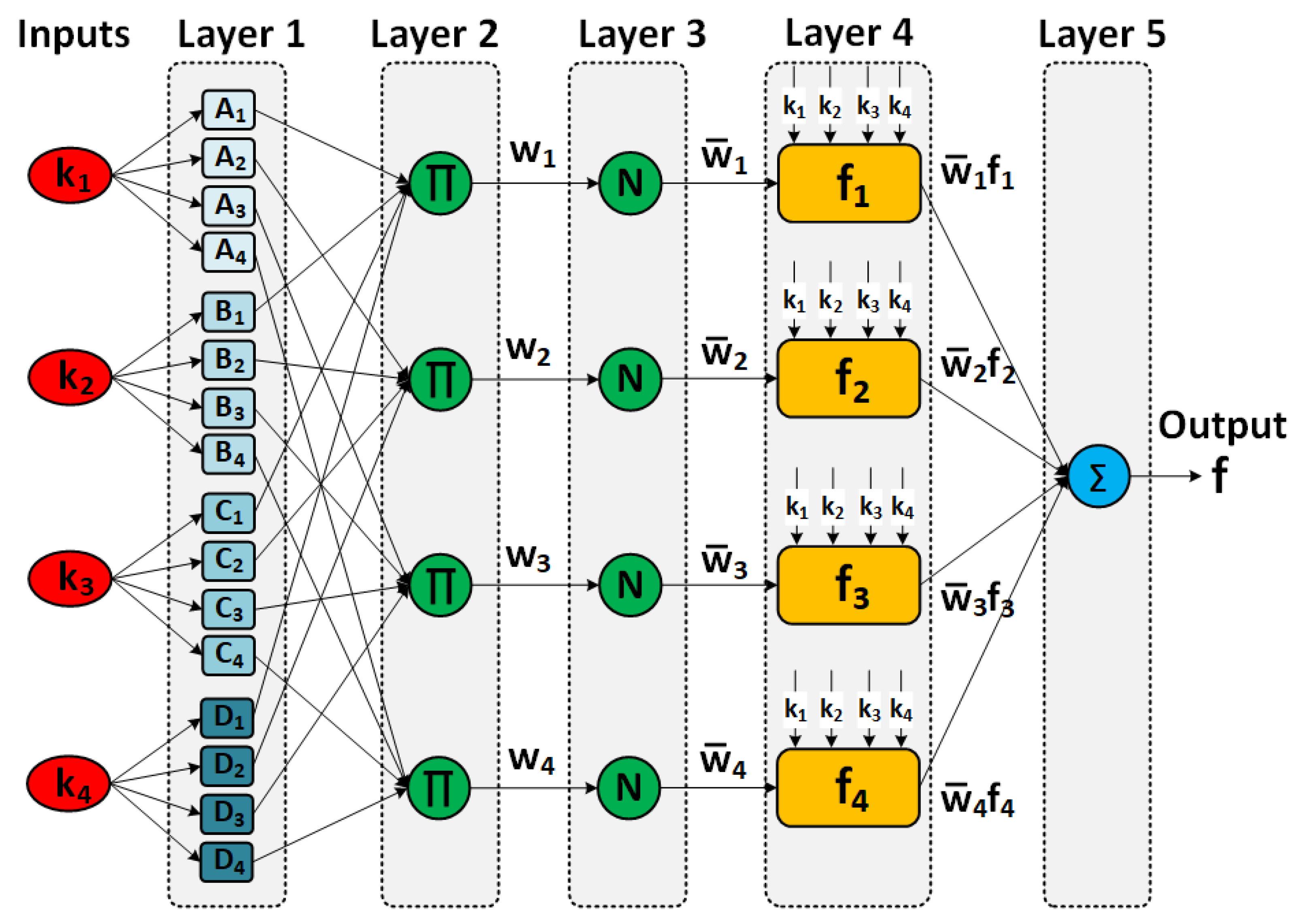
2. ANFIS Design and FDIA Modeling

2.1. ANFIS Design

Power systems, and MGs in particular, use ANNs and Fuzzy Inference Systems (FIS) in a wide range of applications. The ANFIS was designed to take advantage of the ANNs’ learning ability and the rule-based fuzzy logic system inference capability. ANFIS learning is a hybrid learning method that can form the relationship between the input and output based on knowledge inference and input–output data [37]. The effectiveness of this technique has been proved in nonlinear system modeling, identifying the nonlinear parameters in online control, and predicting time series models’ parameters, just to mention a few.
A FIS system uses fuzzy theory to map inputs to outputs; common components include a fuzzy decision-making unit, fuzzification and defuzzification interfaces, fuzzy membership functions, and fuzzy rules. The fuzzy decision-making unit employs fuzzy if–then rules and fuzzy membership functions to transform the input vector’s fuzzy value into the output vector’s fuzzy value. Five different layers make up a standard ANFIS architecture (shown in Figure 1): fuzzification, implication, normalization, defuzzification, and combination. The ANFIS design procedure and the training phase are discussed in greater depth in [36].

2.2. FDIA Modeling

Generally, the information from the current(s) and voltage(s) measurements in the DC system are the points that are vulnerable to FDIA. Usually, the attacker with sufficient access to the system information tries to manipulate the actual system measurements by adding cleverly designed attack values which negatively affects system performance. For better clarity, the FDIA model expressions for the received signals from the system’s voltage or current sensors can be described as follows, i.e., based on two states: Attacked or Normal.
V d c j ( t ) = { V d c j ( t ) + C j V ( t ) δ = 1 ( Attacked ) V d c j ( t ) δ = 0 ( Normal )
I d c j ( t ) = { I d c j ( t ) + C j I ( t ) δ = 1 ( Attacked ) I d c j ( t ) δ = 0 ( Normal )
where V d c j ( t ) , I d c j ( t ) , and C j ( t ) denote the received signals from the voltage and current sensors and the attack value, respectively [38]. Here, j { 1 , , N } , where N denotes the number of DG units. Based on the value of δ , the presence of an attack is detected. Using this FDIA model, all types of FDI attacks, including time-variant (dynamic attacks) and time-invariant (static attacks) ones and hijacking attacks, can be mathematically represented. In other words, all types of FDIA can be divided into two types of attacks: (a) adding false data to the actual value before injecting it into the system and (b) entirely replacing the actual data with fake data. In the second type, which is also referred to as a hijacking attack, it is acceptable to consider that two false values are simultaneously added to the measured data. The first piece of data can be assumed equal to the measured value with the opposite sign ( V d c j ( t ) ), and the second piece of data can be considered false data ( C j V ( t ) ).
As mentioned before, in this study, it is assumed that due to the attacker’s adequate level of access to the system information, smartly designed FDIs are generated and added to the actual current(s) and voltage(s) measurements. Thus, different types of FDIs can be considered as C j V ( t ) and C j I ( t ) in the attack model expressions, which are added to the voltage and current measurements. It should be noted that since the proposed framework in this paper employs a modeling approach that is only valid for FDIA, it can only detect and mitigate FDIA attacks, which is the main focus of this paper.

3. Proposed Method

In general, all crucial data are collected in the monitoring center (MC) as part of the distributed control strategy in DCMGs to evaluate system performance. Since all data are available in the MC, two different DD-based estimators are used in each DG, considering the estimated voltage and current of each DC/DC converter. It is important to note that due to the scalability of the proposed framework, it can be extended for FDI attacks detection and mitigation in a DCMG system with N DGs. The main FDIA detection framework is shown in Figure 2.
The offline phase is associated with the training of ANFIS estimators. The trained ANFIS is implemented in the online phase to estimate the output DC voltage and current of the jth DC/DC converter in a DCMG. Since the output current and voltage vulnerability rate to cyber-attacks in the DCMGs are the same, also for more simplicity, two separate ANFIS models are considered. Using two separate ANFIS for each DG reduces the computational time significantly. It makes the system more efficient in finding the exact place of intrusion, either in voltage or current sensors. The proposed FDIA detection and mitigation framework has five main phases: pre-data acquisition phase, offline training phase, online output prediction phase, online CP detection phase, and mitigation phase.

3.1. Pre-Data Acquisition Phase

In the pre-data acquisition phase, all DGs’ outputs (voltage and current) are collected and combined to form the input vector for the next step in the training phase. The voltage and current outputs of the connected DGs serve as inputs to the ANFISs. All of the acquired data are measured by individual smart meters at the DC bus of the DCMG system. Since the time of FDIA detection is critical for the system’s performance, the quality of input data plays a key role. The input data should be collected at a high sampling rate to have a better training process in the following phases. However, a high sampling rate is directly proportional to the amount of collected data, thereby significantly increasing the computational burden. Therefore, a trade-off decision must be made between the required quality of inputs and the computation burden of the pre-data acquisition. For this purpose, offline simulations were used to collect data for training sets, in various likely scenarios, such as changes in the source input voltage and different load profiles. Hence, a long simulation with a wide diversity of scenarios is conducted by considering all permutations of the likely changes in the DC source voltage and load profiles. According to the number of input variables (four voltages for DC sources and four load values), eight input variables are defined for data collection. Thus, according to all possible permutations of these 8 variables, 8ǃ (=40,320) possible scenarios based on different values for each variable in a range of 0–100% could be defined. After experimenting with various distributions for selecting these input values, the accuracy of the estimators is slightly better when using the Gaussian distribution for modeling input data than other distributions, such as the Laplace and continuous uniform distributions (less than 5% improvement). Therefore, a Gaussian distribution is considered for these possible values. Each of these scenarios is applied to simulation inputs, and 10 different samples are collected as the overall behavior of the system performance from each scenario for the training set. Thus, 40,320 * 10 input samples are collected for each training set.
In addition, for each output voltage and current of the jth DG units, two training sets ( T r _ s e t j V and T r _ s e t j I ) are collected from past historical input and output data to train ANFISs to make accurate dynamic predictions.
T r _ S e t V = ( V 1 ( t ) V i ( t ) y 1 ( t ) V 1 ( t t s ) V i ( t t s ) y 1 ( t t s ) V 1 ( t 2 t s ) V i ( t 2 t s ) y 1 ( t 2 t s ) V 1 ( t p t s ) V i ( t p t s ) y 1 ( t m t s ) )
T r _ S e t I = ( I 1 ( t ) I i ( t ) y 2 ( t ) I 1 ( t t s ) I i ( t t s ) y 2 ( t t s ) I 1 ( t 2 t s ) I i ( t 2 t s ) y 2 ( t 2 t s ) I 1 ( t p t s ) I i ( t p t s ) y 2 ( t m t s ) )
where p, m, i, ts and y are the input-memory order, output-memory order, the inputs sample number, the sample time, and the outputs, respectively.

3.2. Offline Training Phase

In this phase, based on the obtained information from the previous step, the offline training of the ANFIS is performed. To achieve better performance and avoid overfitting during the training phase, these data should be randomly divided into three sets: training, validation, and testing. A large number of input data can be considered for the training set, which can be critical in avoiding overfitting, which has negative impacts such as poor prediction and high testing error. The validation data set should be used to evaluate the error immediately after each epoch to reduce the likelihood of overfitting. The training, validation, and testing data set percentages have been set to 70%, 15%, and 15%, respectively. As mentioned before, FIS training depends highly on the input data. Accordingly, the primary FIS is generated by the subtractive clustering method. Then, ANFIS attempts to find a better input–output domain mapping using the hybrid learning method, which is enhanced during the training phase. An error index is considered to measure the training performance and enhance the mapping ability. In Figure 1b, the offline training phase of the proposed method is shown.

3.3. Online Output Prediction Phase

In this phase, for each DG, two trained estimators are utilized to predict the estimated values ( V ^ o u t D G j and I ^ o u t D G j ) for actual output voltage ( V o u t D G j ) and actual output current ( I o u t D G j ) of each DC/DC converter. In Figure 1c, the proposed online prediction scheme is shown. Two dynamic error signals for each output voltage ( e r r o r V D G j ( t ) ) and current ( e r r o r I D G j ( t ) ) are available for the following steps.
e r r o r V D G j = V o u t D G j ( t ) V ^ o u t D G j ( t )     C ^ j V ( t )  
e r r o r I D G j = I o u t D G j ( t ) I ^ o u t D G j ( t )     C ^ j I ( t )    
In the presence of a cyber-attack, these error signals are nearly equal to the attack values ( C j V ( t ) ,   C j I ( t ) ), and in normal mode, when no attack has been detected in the system, they are approximately equal to zero. Here, C ^ j V ( t ) and C ^ j I ( t ) are the attack values’ approximations that are nearly equal to the attack values.

3.4. Online Change Point Detection Phase

During this phase, the FDIA detection scheme should determine the system status, namely normal and attacked, by interpreting the data from the error signals e r r o r V D G j ( t ) and e r r o r I D G j ( t ) . By using an OCPD, any CPs in the error signal curves are detected, which is a sign of the presence of an attack in the system. In Bayesian Change Point Detection (BCPD), all sample data should be divided into non-overlapping state partitions, assuming that each state’s data are independent and identically distributed from a probability distribution. Moreover, the BCPD tries to compute the probability distribution of the length of the current “run”, or time since the last CP, using a simple message-passing algorithm [39]. In BCPD, the posterior probability distribution is estimated by defining an auxiliary variable run length ( r t ) that shows the elapsed time after the last CP. The probability distribution equation is shown here:
P ( r t | r t 1 ) = { H ( r t 1 + 1 ) i f   r t = 0 1 H ( r t 1 + 1 ) i f   r t = r t 1 + 1 0 o t h e r w i s e
H ( τ ) = P g a p ( g = τ ) t = τ P g a p ( g = τ )
H(τ) is the hazard function, which is shown as the ratio of probability density over the run to the total sum of probability densities, where P g a p ( g ) is a discrete exponential distribution with time scale λ , and H ( τ ) is constant and equal to 1 λ . After calculating the run-length probability distribution, the CP prediction is performed by comparing the run-length probability distribution while updating the probability distribution. A CP occurs when r t has the highest probability in the distribution. In this step, r t is reset to zero ( r t = 0 ); otherwise, r t is incremented by one ( r t = r t 1 ). For further details, see [40].
Based on the above procedure, the error signal’s statistical characteristics (probability distribution) begin to change after the first sampling time of the injected FDIA into the systems. It should be noted that any changes in the first error signal indicate the attacked DG. For instance, if the FDIA occurs in a voltage sensor in DG 3, the error signal of the DG 3 output DC voltage starts to change. As mentioned before, this approach not only detects the existence of FDIA in DCMG but also pinpoints the exact location of a cyber intrusion.

3.5. Mitigation Phase

Following the detection of a cyber-attack as well as the location of the intrusion in the cyber layer, the control system attempts to mitigate the negative consequences of FDIA. Because of the possibility of gaining access to both false and estimated output data from the associated attacked DGs, a compensatory action is taken based on the proposed approach below.
V d c j a m e n d e d ( t ) = { V d c j ( t ) ( Normal ) V d c j a t t a c k ( t ) s i g n ( C ^ j V ( t ) ) | C ^ j V ( t ) | ( Attacked )
I d c j a m e n d e d ( t ) = { I d c j ( t ) ( Normal ) I d c j a t t a c k ( t ) s i g n ( C ^ j I ( t ) ) | C ^ j I ( t ) | ( Attacked )
The absolute value of the difference between the attacked and approximation of the actual data ( C ^ j V ( t ) ,   C ^ j I ( t ) ) but with the opposite sign is added to the attacked data as a new approximation of the actual data obtained from the neighbors. In other words, the secondary controller receives amended data ( V d c j a m e n d e d ( t ) , I d c j a m e n d e d ( t ) ), which are approximately actual and safe instead of false data for the following control subsystem, keeping the system running as if there was no attack.

4. Simulation Results

The test system that is shown in Figure 3 is commonly considered to study attack presence conditions and evaluate the attack detection and mitigation efficiency [13,20]. The system includes four RES units (with DC source) interfaced by DC/DC converters, four impedance distributed lines that connect the DGs, and four DC loads fed by the network. The voltage reference of the DCMG is 315 V. The testbed DCMG’s specification is presented in Table 1.
To evaluate the effectiveness of the proposed framework to deal with FDIs that are not detectable with traditional bad data detection methods, four different attack scenarios including simultaneous abrupt load change and FDI, time-varying FDI, hijacking and Gaussian distributed attacks are introduced with the properties listed in Table 2. In each scenario, various cases with different attack parameters are considered. However, to preserve the brevity of the paper, one representative case is investigated in each scenario.

4.1. Scenario 1: Abrupt Load Change and FDIA

One of the challenging attack scenarios in FDIA detection is when the attacker injects false data into the network during abrupt load changes, as shown in Figure 4.
For instance, DG 1 is attacked, while loads 4 and 2 increase by 45% and 25% at t = 3.6 and t = 4.6, respectively. Therefore, the FDIA detection method should distinguish between the abrupt load changes and actual intrusion, which is not a straightforward task because of the same instant effects (changes in average output voltage and sharing the current consequently) on the system performance. The output voltage of the DCMG without the attack detection scheme and the output voltage and currents with the attack detection and mitigation control method is shown in Figure 4b for comparison. As shown in Figure 4c, two other abrupt load changes occur before and during an actual intrusion, and the detection method does not consider those as an intrusion. In Figure 4e, the error signals ( e r r o r V D G i ( t ) ) for DGs are presented. Obviously, due to the attack occurrence in voltage sensor data from the connected neighbors in DG 1, the related error signal is the largest and starts to change before the others. In the proposed mitigation scheme, the absolute difference between ANFIS estimates and tampered data with the opposite sign is added to the manipulated unit’s tampered data. These new signals are considered as an approximation of safe data and are given as input to the control system to recover the pre-attack performance. Hence, it is not required to plug out the attacked unit during the intrusion, as manipulated data will not affect the controller’s performance.

4.2. Scenario 2: Time-Varying FDIA in Transmitted Current Sensor Measurement

In this scenario, the injected false data are considered as two sine waves in the current sensor measurements of DG 2 and DG 4. The attacker injects the time-varying false data into the communication layer, while some abrupt load change occurs in the time interval [4.0, 6.0] s, as shown in Figure 5a.
Furthermore, as shown in Figure 5b, two other abrupt load changes occur before an actual intrusion, and the detection system does not consider those as an attack. The output currents when the attack detection scheme does not exist are illustrated in Figure 5b for better comparison. As shown in Figure 5b, for the system without the proposed attack detection framework, DG 2 and DG 4 lose their current-sharing capabilities due to receiving manipulated data from the cyber communication layer in their control units. The error signals ( e r r o r I D G i ( t ) ) for DGs are shown in Figure 5e.
Due to the false data attack occurrence in the current sensor measurements of DG 2 and DG 4, the related error signals (DG 4 and DG 2) begin to change, which may cause some CPs that are detected by the OCPD scheme. Due to various measurement and communication delays in this study, the detecting process in DG 4 is completed earlier than in DG 2.

4.3. Scenario 3: Hijacking Attack

The hijacking attack is one of the most challenging types of FDIA since the actual data are entirely replaced with the fake one. Thus, it does not follow the exact characteristics of the actual data, such as the slope of change and the limited amplitude, as described in Scenario 1. In this scenario, it is assumed that the intrusion is placed on the voltage sensor in DG 2. In Figure 6, the performance of the proposed method is shown in the presence of a hijacking attack on the voltage sensor.
As described in Scenario 1, the results show that the proposed method not only can detect the hijacking attack but also distinguishes between abrupt load changes and intrusions. Based on the attack properties in Table 2, the presence of an attack is detected by the proposed method in DG 2 (Figure 6e); the final status of the detection system in the presence of the intrusion is also shown in Figure 6f. It is worth mentioning that utilizing this method can successfully detect and mitigate all the FDIA even though all units are under attack.

4.4. Scenario 4: Gaussian Distributed Attack

One of the other challenging and common types of FDIA, which is likely to occur in DCMGs, is evaluated in this scenario. In this scenario, the performance evaluation is studied in the presence of a Gaussian-distributed attack. In this attack, the attacker tries to conceal its malicious activities by injecting false data that looks like regular load profile changes and has an almost similar trend to a Gaussian distribution.
Similar to the previous scenarios, the load profile, output DC voltage, and current with and without utilizing the proposed attack detection and mitigation scheme are presented in Figure 7a–c, respectively. As depicted in Figure 7b and all similar graphs in the previous scenarios, it is obvious that the consensus is lost when the attack is injected into the typical DCMG, which is not equipped with an attack detection and mitigation scheme. Finally, the attack detection system’s error analysis and final status in the presence of the Gaussian-distributed FDIA are illustrated in Figure 7e,f, respectively.

5. Conclusions and Future Work

A data-driven-based framework for detecting and mitigating FDIA in DCMGs was proposed in this paper. The proposed method used the ANFIS to estimate the DC outputs of all DGs in a DCMG with 99.40% accuracy. The transient and steady-state error between the estimation and measured data converges to a non-zero value as soon as any false data are injected into the DCMG. Based on the estimation error, the proposed method can not only identify the intrusion’s existence and location but also mitigate the negative consequences of the FDIA in the system. Furthermore, the proposed method does not need to access an extra secure communication line to detect the place of intrusion. It can also detect the various types of FDIA without needing to model those attacks in the training process.
In addition, there is no need to plug out the attacked unit during a malicious intrusion. The proposed method’s performance was validated using real-time simulations in the MATLAB/Simulink environment to evaluate its efficiency and accuracy under different scenarios. The results demonstrated that the FDIA presence and the attacked DG unit are detected and successfully mitigated in both transient and steady-state conditions. Extending the proposed framework by adding an online learning capability for maintaining the system performance over time which also address the scalability issue of the proposed framework are subjects of future studies by the authors.

Author Contributions

Conceptualization, A.B.; methodology, A.B.; software, A.B.; validation, A.B.; formal analysis, A.B.; visualization, A.B.; writing—original draft preparation, A.B.; writing—review and editing, A.B., J.M.G., J.C.V., N.B. and S.G.; supervision, J.M.G. and J.C.V. All authors have read and agreed to the published version of the manuscript.

Funding

This work was supported by VILLUM FONDEN, Denmark, under the VILLUM Investigator Grant (no. 25920); Center for Research on Microgrids (CROM), www.crom.et.aau.dk (accessed on 14 November 2022).

Data Availability Statement

Available upon request.

Conflicts of Interest

The authors declare no conflict of interest.

Nomenclature

InIndices
jIndex of DG units
nIndex of ANFIS inputs
lIndex of membership functions
Parameters
Al, Bl, Cllth Membership functions for each ANFIS inputs
w l Weighting factor
w l ¯ The normalized value of the weighting factor
𝑃nominal jNominal power output of unit jth
D G j V Place of attack intrusion in voltage sensor for DG unit jth
D G j I Place of attack intrusion in current sensor for DG unit jth
I d c j m a x The maximum output current of DG unit jth
pInput-memory order for training sets
mOutput-memory order for training sets
hInputs sample number for training sets
tsSampling time for training sets
Variables
f n The final crisp output of the defuzzification layer for nth inputs
V d c j ( t ) Measured output voltage signal of DG unit jth
I d c j ( t ) Measured output current signal of DG unit jth
V ^ o u t D G j   The predicted output voltage of DG unit jth
I ^ o u t D G j The predicted output current of DG unit jth
C j V ( t ) Attack value in the voltage sensor for DG unit jth
C j I ( t )   Attack value in the current sensor for DG unit jth
C ^ j V ( t ) Attack value’s approximation in voltage sensor for DG unit jth
C ^ j I ( t ) Attack value’s approximation in current sensor for DG unit jth
e r r o r V D G j ( t ) Voltage error signal for DG unit jth
e r r o r I D G j ( t ) Current error signal for DG unit jth
V d c j a m e n d e d ( t ) Amended output voltage signal for DG unit jth
I d c j a m e n d e d ( t ) Amended output current signal for DG unit jth
r t   Variable run-length in the BCPD method
P ( r t | r t 1 ) Probability distribution in the BCPD method
H ( τ ) Hazard function in the BCPD method
P g a p ( g ) Discrete exponential probability distribution
A m p   The amplitude of the attack signal
F r q The frequency of the attack signal
D C   g a i n DC gain of the attack signal
𝐿j Inductance value of the DC/DC converter for DG unit jth
𝐶𝑑𝑐jCapacitance value of the DC/DC converter for DG unit jth
𝑃𝑙jConnected local load power for DG unit jth
Sets
T r _ s e t j V ANFIS training set for output voltage for DG unit jth
T r _ s e t j I ANFIS training set for output current for DG unit jth
Abbreviations
DCMGDC Microgrid
ACMGAC Microgrid
ANFISAdaptive Neuro-Fuzzy Inference System
DGDistributed Generation
DDData Driven
OCPDOnline Change Point Detection
RESRenewable Energy Source
PVPhotovoltaic
FDIAFalse Data Injection attack
DoSDenial of Service
MITMMan in the Middle
SCADASupervisory Control and Data Acquisition
ANNArtificial Neural Network
FISFuzzy Inference System
BCPDBayesian Change Point Detection
VSCVoltage Sourced Converter
MCMonitoring Center
SVEState Vector Estimation
FFNNFeedforward Neural Network
DTDecision Tree

References

  1. Bajwa, A.A.; Mokhlis, H.; Mekhilef, S.; Mubin, M. Enhancing Power System Resilience Leveraging Microgrids: A Review. J. Renew. Sustain. Energy 2019, 11, 035503. [Google Scholar] [CrossRef]
  2. Dragičević, T.; Lu, X.; Vasquez, J.C.; Guerrero, J.M. DC Microgrids—Part I: A Review of Control Strategies and Stabilization Techniques. IEEE Trans. Power Electron. 2016, 31, 4876–4891. [Google Scholar]
  3. Dragičević, T.; Lu, X.; Vasquez, J.C.; Guerrero, J.M. DC Microgrids—Part II: A Review of Power Architectures, Applications, and Standardization Issues. IEEE Trans. Power Electron. 2016, 31, 3528–3549. [Google Scholar] [CrossRef] [Green Version]
  4. Maknouninejad, A.; Qu, Z.; Lewis, F.L.; Davoudi, A. Optimal, Nonlinear, and Distributed Designs of Droop Controls for DC Microgrids. IEEE Trans. Smart Grid 2014, 5, 2508–2516. [Google Scholar] [CrossRef]
  5. Hao, L.; Ji, J.; Xie, D.; Wang, H.; Li, W.; Asaah, P. Scenario-based unit commitment optimization for power system with large-scale wind power participating in primary frequency regulation. J. Mod. Power Syst. Clean Energy 2020, 8, 1259–1267. [Google Scholar] [CrossRef]
  6. Rayati, M.; Sheikhi, A.; Ranjbar, A.M.; Sun, W. Optimal Equilibrium Selection of Price-maker Agents in Performance-based Regulation Market. J. Mod. Power Syst. Clean Energy 2020, 10, 204–212. [Google Scholar] [CrossRef]
  7. Becker, D.J.; Sonnenberg, B.J. DC microgrids in buildings and data centers. In Proceedings of the IEEE 33rd International Telecommunications Energy Conference (INTELEC), Amsterdam, The Netherlands, 9–13 October 2011. [Google Scholar]
  8. Xu, L.; Guerrero, J.M.; Lashab, A.; Wei, B.; Bazmohammadi, N.; Vasquez, J.; Abusorrah, A.M. A Review of DC Shipboard Microgrids Part I: Power Architectures, Energy Storage and Power Converters. IEEE Trans. Power Electron. 2021, 37, 5155–5172. [Google Scholar] [CrossRef]
  9. Magne, P.; Nahid-Mobarakeh, B.; Pierfederici, S. Active stabilization of DC microgrids without remote sensors for more electric aircraft. IEEE Trans. Ind. Appl. 2013, 49, 2352–2360. [Google Scholar] [CrossRef]
  10. Basati, A.; Fakharian, A.; Guererro, J.M. An intelligent droop control for improve voltage regulation and equal power sharing in islanded DC microgrids. In Proceedings of the 2017 5th Iranian Joint Congress on Fuzzy and Intelligent Systems (CFIS), Qazvin, Iran, 7–9 March 2017. [Google Scholar]
  11. Basati, A.; Wu, J.; Guerrero, J.M.; Vasquez, J.C. Internal Model-based Voltage Control for DC Microgrids Under Unknown External Disturbances. In Proceedings of the 5th International Conference on Smart Energy Systems and Technologies, Eindhoven, The Netherlands, 5–7 September 2022. [Google Scholar]
  12. Bagheri Rouch, T.; Fakharian, A. Robust Control of Islanded DC Microgrid for Voltage Regulation Based on Polytopic Model and Load Sharing. Iran. J. Sci.Technol. Trans. Electr. Eng. 2022, 46, 171–186. [Google Scholar] [CrossRef]
  13. Sahoo, S.; Mishra, S. A Distributed Finite-Time Secondary Average Voltage Regulation and Current Sharing Controller for DC Microgrids. IEEE Trans. Smart Grid 2019, 10, 282–292. [Google Scholar] [CrossRef]
  14. Basati, A.; Menhaj, M.B.; Fakharian, A. GA-based optimal droop control approach to improve voltage regulation and equal power sharing for islanded DC microgrids. In Proceedings of the Electric Power Quality and Supply Reliability (PQ), Tallin, Estonia, 29–31 August 2016. [Google Scholar]
  15. Shafiee, Q.; Dragičević, T.; Vasquez, J.C.; Guerrero, J.M. Hierarchical control for multiple DC-microgrids clusters. IEEE Trans. Energy Convers. 2014, 29, 922–933. [Google Scholar] [CrossRef]
  16. Guerrero, J.M.; Chandorkar, M.; Lee, T.-L.; Loh, P.C. Advanced Control Architectures for Intelligent Microgrids—Part I: Decentralized and Hierarchical Control. IEEE Trans. Ind. Electron. 2013, 60, 1254–1262. [Google Scholar] [CrossRef] [Green Version]
  17. Tan, S.; Guerrero, J.M.; Xie, P.; Han, R.; Vasquez, J.C. Brief Survey on Attack Detection Methods for Cyber-Physical Systems. IEEE Syst. J. 2020, 14, 5329–5339. [Google Scholar] [CrossRef]
  18. Tan, S.; Xie, P.; Guerrero, M.J.; Vasquez, C.J. False Data Injection Cyber-Attacks Detection for Multiple DC Microgrid Clusters. Appl. Energy 2022, 310, 118425. [Google Scholar] [CrossRef]
  19. Habibi, M.R.; Sahoo, S.; Rivera, S.; Dragičević, T.; Blaabjerg, F. Decentralized Coordinated Cyberattack Detection and Mitigation Strategy in DC Microgrids Based on Artificial Neural Networks. IEEE J. Emerg. Sel. Top. Power Electron. 2021, 9, 4629–4638. [Google Scholar] [CrossRef]
  20. Sahoo, S.; Mishra, S.; Peng, J.C.; Dragičević, T. A Stealth Cyber-Attack Detection Strategy for DC Microgrids. IEEE Trans. Power Electron. 2019, 34, 8162–8174. [Google Scholar] [CrossRef] [Green Version]
  21. Liu, Y.; Peng, Y.; Wang, B.; Yao, S.; Liu, Z. Review on cyber-physical systems. IEEE/CAA J. Autom. Sin. 2017, 4, 27–40. [Google Scholar] [CrossRef]
  22. Hu, S.; Yuan, P.; Yue, D.; Dou, C.; Cheng, Z.; Zhang, Y. Attack-Resilient Event-Triggered Controller Design of DC Microgrids Under DoS Attacks. IEEE Trans. Circuits Syst. I Regul. Pap. 2020, 67, 699–710. [Google Scholar] [CrossRef]
  23. Sahoo, S.; Peng, J.C.; Mishra, S.; Dragičević, T. Distributed Screening of Hijacking Attacks in DC Microgrids. IEEE Trans. Power Electron. 2020, 35, 7574–7582. [Google Scholar] [CrossRef]
  24. Mo, Y.; Weerakkody, S.; Sinopoli, B. Physical authentication of control systems: Designing watermarked control inputs to detect counterfeit sensor outputs. IEEE Control. Syst. 2015, 35, 93–109. [Google Scholar]
  25. Irita, T.; Namerikawa, T. Detection of replay attack on smart grid with code signal and bargaining game. In Proceedings of the American Control Conference (ACC), Seattle, WA, USA, 24–26 May 2017. [Google Scholar]
  26. Yang, Y.; Wei, X.; Xu, R.; Peng, L.; Zhang, L.; Ge, L. Man-in-the-Middle Attack Detection and Localization Based on Cross-Layer Location Consistency. IEEE Access 2020, 8, 103860–103874. [Google Scholar] [CrossRef]
  27. Sahoo, S.; Dragičević, T.; Blaabjerg, F. Multilayer Resilience Paradigm Against Cyber Attacks in DC Microgrids. IEEE Trans. Power Electron. 2021, 36, 2522–2532. [Google Scholar] [CrossRef]
  28. Ahmed, M.; Pathan, A.S. False data injection attack (FDIA): An overview and new metrics for fair evaluation of its countermeasure. Complex Adapt. Syst. Model. 2020, 8, 4. [Google Scholar] [CrossRef] [Green Version]
  29. Hao, J.; Kang, E.; Sun, J.; Wang, Z.; Meng, Z.; Li, X.; Ming, Z. An Adaptive Markov Strategy for Defending Smart Grid False Data Injection From Malicious Attackers. IEEE Trans. Smart Grid 2018, 9, 2398–2408. [Google Scholar] [CrossRef]
  30. Chaojun, G.; Jirutitijaroen, P.; Motani, M. Detecting False Data Injection Attacks in AC State Estimation. IEEE Trans. Smart Grid 2015, 6, 2476–2483. [Google Scholar] [CrossRef]
  31. Ozay, M.; Esnaola, I.; Vural, F.T.Y.; Kulkarni, S.R.; Poor, H.V. Machine Learning Methods for Attack Detection in the Smart Grid. IEEE Trans. Neural Netw. Learn. Syst. 2016, 27, 1773–1786. [Google Scholar] [CrossRef] [PubMed] [Green Version]
  32. Wilson, D.; Tang, Y.; Yan, J.; Lu, Z. Deep Learning-Aided Cyber-Attack Detection in Power Transmission Systems. In Proceedings of the IEEE Power & Energy Society General Meeting (PESGM), Portland, OR, USA, 5–9 August 2018; pp. 1–5. [Google Scholar]
  33. He, Y.; Mendis, G.J.; Wei, J. Real-Time Detection of False Data Injection Attacks in Smart Grid: A Deep Learning-Based Intelligent Mechanism. IEEE Trans. Smart Grid 2017, 8, 2505–2516. [Google Scholar] [CrossRef]
  34. Habibi, M.R.; Baghaee, H.R.; Dragičcevi’c, T.; Blaabjerg, F. Detection of False Data Injection Cyber-Attacks in DC Microgrids based on Recurrent Neural Networks. IEEE J. Emerg. Sel. Top. Power Electron. 2020, 9, 5294–5310. [Google Scholar] [CrossRef]
  35. Bayati, N.; Hajizadeh, A.; Soltani, M. Blockchain-based protection schemes of DC microgrids. In Blockchain-Based Smart Grids; Academic Press: Cambridge, MA, USA, 2020; pp. 195–214. [Google Scholar]
  36. Basati, A.; Bazmohammadi, N.; Guererro, J.M.; Vasquez, J.C. Real-Time Estimation in Cyber Attack Detection and Mitigation Framework for DC Microgrids. In Proceedings of the 2022 Interdisciplinary Conference on Mechanics, Computers and Electrics (ICMECE), Barcelona, Spain, 6–7 October 2022. [Google Scholar]
  37. Jang, J.R. ANFIS: Adaptive-network-based fuzzy inference system. IEEE Trans. Syst. Man Cybern. 1993, 23, 665–685. [Google Scholar] [CrossRef]
  38. Zhang, J.; Sahoo, S.; Peng, J.C.-H.; Blaabjerg, F. Mitigating Concurrent False Data Injection Attacks in Cooperative DC Microgrids. IEEE Trans. Power Electron. 2021, 36, 9637–9647. [Google Scholar] [CrossRef]
  39. Adams, R.P.; MacKay, D.J. Bayesian online changepoint detection. arXiv 2007, arXiv:0710.3742. [Google Scholar]
  40. Aminikhanghahi, S.; Cook, D.J. A survey of methods for time series change point detection. Knowl. Inf. Syst. 2017, 51, 339–367. [Google Scholar] [CrossRef] [PubMed]
Figure 1. ANFIS architecture.
Energies 15 08539 g001
Figure 2. Proposed FDIA detection and mitigation framework: (a) Physical power system, (b) Offline training phase implementation, (c) Online FDI detection and mitigation phase.
Energies 15 08539 g002
Figure 3. The testbed DCMG with the related communication network (adapted from [13]).
Energies 15 08539 g003
Figure 4. System performance in the presence of voltage sensor FDIAs: (a) Load profiles. (b) Output DC voltages of a standard secondary controller. (c) Output DC voltages with proposed method (d) Output current with proposed method. (e) Error signals. (f) Final status of DGs in attack presence.
Energies 15 08539 g004
Figure 5. System performance in the presence of current sensor FDIAs: (a) Load profiles. (b) Output current of a standard secondary controller. (c) Output DC voltages with proposed method. (d) Output current with proposed method. (e) Error signals. (f) Final status of DGs in attack presence.
Energies 15 08539 g005
Figure 6. System performance in the presence of hijacking attack in voltage sensor: (a) Load profiles. (b) Output DC voltages of a standard secondary controller. (c) Output DC voltages with proposed method. (d) Output current with proposed method. (e) Error signals. (f) Final status of DGs in attack presence.
Energies 15 08539 g006
Figure 7. System performance in the presence of Gaussian-distributed attack in voltage sensor: (a) Load profiles. (b) Output DC voltages of a standard secondary controller. (c) Output DC voltages with proposed method. (d) Output current with proposed method. (e) Error signals. (f) Final status of DGs in terms of attack presence.
Energies 15 08539 g007
Table 1. Specifications of the testbed DCMG.
DGsDG 1DG 2DG 3DG 4
𝑃nominal1,2 ≃ 4.7 kW𝑃nominal3,4 ≃ 3.1 kW
Converter𝐿𝑖 = 300 μH, 𝐶𝑑𝑐𝑖 = 250 μF
I d c 1 , 2 m a x = 15 I d c 3 , 4 m a x = 10
LineT12T23T34T14
R = 0.5 Ω
L = 80 μH
R = 2.5 Ω
L = 85 μH
R = 3.3 Ω
L = 95 μH
R = 2.3 Ω
L = 70 μH
LoadLaod 1Laod 2Laod 3Laod 4
𝑃𝑙1 ≃ 3.4 kW𝑃𝑙2 ≃ 3.7 kW𝑃𝑙3 ≃ 2.9 kW𝑃𝑙4 ≃ 3.1 kW
Table 2. Attack properties.
Scenario No.Place of
Intrusion
Type of Attack (Sine Waves 1, 2, 3 and Gaussian 4)Period of
Attack
1 D G 1 V C 1 V ( t ) : A m p = 5 ± 1.5 , F r q = 5 ± 1.5   Hz ,
D C   g a i n = 5 ± 1.5
t = [5.1, 7.3] s
2 D G 2 I , D G 4 I C 2 , 4 I ( t ) : A m p = 10 ± 2.5 ,
F r q = 5 ± 2.5   Hz , D C   g a i n = 4 ± 2.5  
t = [4.0, 6.0] s
3 D G 2 V C 2 V ( t ) : A m p = 15 ± 2.5 ,
F r q = 10 ± 2.5   Hz ,   D C   g a i n = 3 ± 2.5
t = [5.0, 7.0] s
4 D G 4 V C 4 V ( t ) :   μ = 4.25 ,   σ = 0.35 ,   D C   g a i n = 2.2 t = [3.0, 5.5] s
Publisher’s Note: MDPI stays neutral with regard to jurisdictional claims in published maps and institutional affiliations.

