Article

Development of Future Compact and Eco-Friendly HVDC Gas Insulated Systems: Test Verification of Shape-Optimized DC Spacer Models

1
Advanced High Voltage Engineering (A-HIVE) Research Centre, Cardiff University, Cardiff CF24 3AA, UK
2
Mekufa UK Ltd., Gloucester GL1 5SR, UK
*
Author to whom correspondence should be addressed.
Energies 2022, 15(22), 8563; https://doi.org/10.3390/en15228563
Submission received: 19 September 2022 / Revised: 2 November 2022 / Accepted: 14 November 2022 / Published: 16 November 2022
(This article belongs to the Special Issue Advances in High Voltage Engineering)

Abstract

:
Spacers for the HVDC GIS/GIL play an important role in mechanically supporting conductors and separating compartments. At the same time, their insulation performance affects the stability and safety of system operation. Design rules and knowledge specific to AC spacers do not apply to those of DC spacers. Considering the shape influence on the surface electric field intensity of the spacer under HVDC applied voltage, as determined in our previous work, an optimized shape of a spacer model based on finite element electric field calculations and using standard HVAC alumina filled epoxy material and two novel types of materials were studied. The simulation’s results show that the DC shape optimization of the spacers can effectively reduce the electric field magnitudes along the spacer under different temperature gradients. To verify practically these findings, this paper presents the reduced scale gas insulated prototype that was constructed, the optimized DC spacers that were fabricated and the DC testing results using SF6-free surrounding gas: C4-Perfluoronitrile (C4-PFN, 3MTM NovecTM 4710)/CO2 and Trifluoroiodomethane (CF3I)/CO2. The results show that the shape-optimized spacer models made of conventional HVAC filled epoxy material have successfully passed the tests up to the maximum applicable ±123 kV DC exceeding thus ±119 kV DC that corresponds to the nominal voltage ±500 kV DC of the full scale.

1. Introduction

Whilst high voltage gas-insulated switchgears (GIS) and gas-insulated transmission lines (GIL) are well-proven technologies for high-voltage alternating current (HVAC) electricity transmission applications under at least 800 kV AC [1,2], their operation under high voltage direct current (HVDC) is extremely challenging. Therefore, they are currently under development worldwide for the ±550 kV DC rated voltage (maximum continuous operating voltage) and ultra-high voltage (UHV) of ±800 kV DC. The need for next generation UHVDC power transmission over long distances is expected to grow substantially in the coming years.
Among the critical challenges for this development, there is the problem of the epoxy cast resin insulators that are used to separate gas compartments of the GIL/GIS also so-called spacers and to provide mechanical support for high-voltage conductors. Indeed, under steady state DC operating voltage, the electric field distribution along the spacers’ surface is controlled by the electric conductivity, σ, of the epoxy spacers and the surrounding gas through the formula div(σE) = 0, where σ depends on the electric field (E) and strongly on the temperature. So, when the GIL/GIS is under full load operation, a temperature gradient forms from the energized HV conductor to the grounded enclosure due to the DC current flow and, as a result of this, the electric field strength near the conductor reduces while at the same time it increases near the enclosure where the conductivity is lower.
Furthermore, in addition to the effect of the electric conductivity, there is also the shape of the spacer and its contacts with the conductor/enclosure and the surrounding gas called triple junctions, where the electric field can be significantly intensified. Therefore, in order to keep the electric field strength within the permissible level, it is necessary to design the shape of the spacer properly.
In Ref. [3], we presented a review on real-size epoxy cast resin insulators for compact HVDC GIS and GIL as well as current achievements and envisaged research and development. Our main conclusions are:
-
Today’s geometrically optimized full-size DC spacers, by the GIS/GIL manufacturers, are either modified conical shape or disk type and are made of slightly modified chemical composition of the standard HVAC alumina filled epoxy material. It should be noted that detailed information about the manufacturers’ geometry optimization was not revealed.
-
For a further downsizing of HVDC GIL/GIS systems and for UHVDC systems where higher applicable electric field stresses are to be subjected, new advanced insulation technologies need to be considered, such as electric field grading materials and functional graded materials, which are still under development.
-
The developed SF6-free alternative gases: C5-perfluoroketone mixed with CO2 and O2, and C4-perfluoronitile mixed with CO2 have entered the market and are currently used in some commercial HVAC gas insulated systems [4,5]. However, their reliability and compatibility with HVDC GIS/GIL epoxy insulators have not been yet studied and experimentally verified.
Concerning research studies using HVDC spacer models having smaller dimensions (downsized spacers), some electric field distribution calculations based on the spacer shape optimization have been conducted [6,7,8], but without experimental verification. Few experimental investigations have been carried out on the novel spacer shape presented in the works [9,10,11] that we referred to in this paper. Hence, still much to be well understood and solved about spacers for HVDC and UHVDC GIL/GIS applications, so, we decided to concentrate on both numerical and practical aspects.
In our previous paper [12], we presented the simulation results of DC electric field distribution along the surface of an optimized shape of the spacer under a DC applied voltage of 131.3 kV, that corresponds approximately to the rated voltage (maximum continuous operating voltage) of 550 kV DC of full-size scale, by using AC standard alumina filled epoxy material and SF6-free surrounding insulating gas. For this latter, CF3I (30%)/CO2 (70%) and C4-PFN (4%)/CO2 (96%) were designated by assuming having the same electrical DC conductivity behavior as that of SF6. Other materials, such as modified filled epoxy and nonlinear resistive field grading material (FGM) with and without temperature gradient have been also considered using this optimized spacer profile.
The found optimized spacer’s geometry and the resulting DC–electrical field distributions are shown in Figure 1 and Figure 2, respectively [12].
As can be seen in Figure 2, the optimized profile can effectively relax the electric field on the spacer surface. The maximum electric field values are 3.4 kV/mm at the upper surface and 3.2 kV/mm at the lower surface, respectively, and they are not located at the triple junctions (gas-spacer-HV conductor/grounded flange), thus not exceeding the maximum applied electric field of 5.6 kV/mm on the central conductor.
In this paper, we present experimental investigations to verify the performance of the optimized spacer model presented in Figure 1 made of standard alumina and silica filled epoxy materials. A reduced scale gas insulated system to mimic the full size one was designed and constructed. The mold of the spacer was also designed and fabricated. Furthermore, three SF6 free alternative gases were utilized in this investigation which are 4% C4-perfluoronitrile (C4-PFN, 3MTM NovecTM 4710) mixed with 96% CO2, 30% trifluoroiodomethane (CF3I) mixed with 70% CO2 and dry air. This means that the compatibility of these gases with the DC spacers were also taken into account and checked.

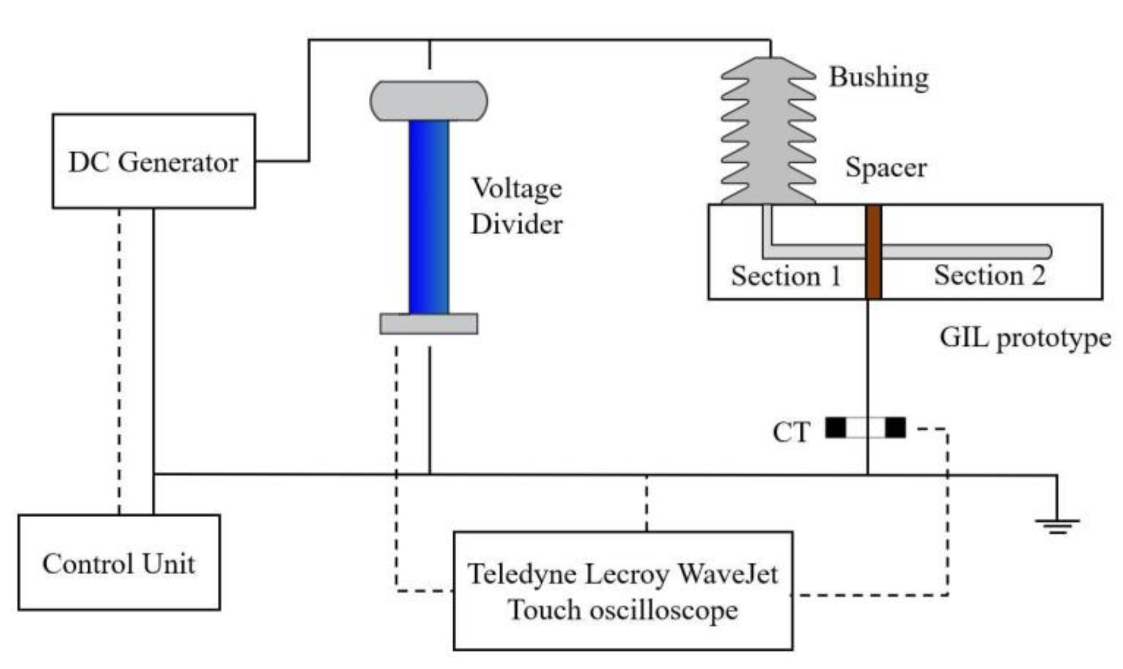
2. Experimental Setup

Figure 3 shows the schematic arrangement for the experimental investigation. It is composed of the reduced scale GIL prototype and the HVDC test setup consisting of:
-
A reduced-scale GIL prototype;
-
A Glassman ± DC generator (Max. ±125 kV) to apply high voltage through a control unit;
-
A voltage divider with the ratio of 2000:1 to reduce the generated voltage to a safe and measurable level;
-
A Stangenes Industries inc. 3-0.1 series current transformer (CT) connected to the GIL prototype to help identify whether a flashover occurred on the surface of the spacer or a breakdown across the gas gap of the prototype.

2.1. GIL Prototype

The prototype is made of stainless steel and is composed of three compartments (Sections 1–3). A central conductor tube is supported by two spacers. Each compartment contains an opening for gas inlet and pressure gauge. The central conductor tube of the GIL prototype is connected to the high voltage (HV) supply through a bushing, and all the compartments are connected to the ground.
It should be noted that the design principle of this prototype is based on a commercial conventional full-size high voltage alternating current (HVAC) 420 kV gas-insulated system reduced to ¼ scale. Namely, the dimensions of the full-size gas-insulated system relative to the outer diameter (DC) of the central conductor and the inner diameter (DE) of the enclosure are downsized by a factor of ¼ (0.25). Thus, the diameter of the inner conductor (DC) and enclosure (DE) of the reduced scale prototype are 48.3 mm and 128.2 mm, respectively, and the gas gap is 39.95 mm. The ¼-size gas-insulated system has been chosen to reproduce the design of the commercial full-size HVAC 420 kV GIL/GIS in such a way to obtain approximately the same applied electric fields at the central HV conductor (EC) and at the grounded enclosure (EE).
Assuming that the 420 kV-AC design can also be used for the rated voltage 550 kV-DC, the resulting electric fields EC and EE are, respectively:
E C = V 1 2 D C · ln D E D C 5.6   kV / mm
E E = V 1 2 D E · ln D E D C 2.0   kV / mm
where V is the applied voltage on the inner conductor
Therefore, the corresponding voltage that was used in the simulations for the reduced scale model is 131.3 kV.
Figure 4 illustrates two installed sections of the GIL prototype (Figure 3) separated by one spacer model. This configuration has been used in the following for the tests’ verification.
The constructed GIL prototype fulfils the requirements of tightness and surface smoothness of the central conductor and the inner surface of the compartments.
Concerning the tightness, this was checked by (i) using water under 15 bar (abs.) for 1 h and also (ii) under vacuum and gas pressure with N2 at 6 bar (abs.), 8 bar (abs.), and 10 bar (abs.).
For the surface smoothness, the roughness of the inner conductor tube and inside the compartments have been measured using Mahr test equipment where it has been found that the arithmetic average of the absolute values of the roughness profile ordinates lies in the range Ra = 0.421–0.967 μm. The surface roughness was measured based on tracing the probe across the surface of the inner conductor tube and inside the compartments. After calibrating the probe, the measuring instrument was placed on its base so that the probe tip is vertical to the surface of the measuring objects. The drive unit then moved the probe over the measuring objects at the preset measuring speed. After the third measurement a correction value was calculated from the three measured values. An example is shown in Figure 5.

2.2. DC Spacers

The mold of the optimized DC spacer was designed (Figure 6) and fabricated (Figure 7) at Cardiff University.
The spacers are made of conventional filled epoxy matrix with alumina (Al2O3), as mentioned above, and also with silica (SiO2). The material formulations and the fabricated spacer models were agreed on and made in collaboration with MEKUFA UK, manufacturer of epoxy resin medium voltage components.
The general procedure to fabricate the spacer models is as follows: The melted epoxy resin is intensively mixed with the dried filler in a thin film degassing mixer under vacuum and then the hardener is added. The ready mixture is fed directly into the preheated spacer mold in the autoclave at 120–140 °C.
It should be noted that the fabrication of the DC spacers was not a trivial task and straightforward. Indeed, the first trials using silica filled epoxy were not successful due to the leak of the melted filled epoxy from the mold during casting as illustrated in Figure 6 leading to imperfections at some locations of the spacers as shown in Figure 8 and resulting in a bad gas tightness at the flanges. As well as defects near the central conductor that would lead to surface flashover during HV testing (Figure 8).
After mold improvement, the desired DC spacers were finally obtained smooth and without any defects as shown in Figure 9.

3. Experimental Procedure

Since SF6 is a greenhouse gas [13], it is not allowed to use it in the laboratory due to the restrictive regulations that require obtaining a license for using the gas, handling and recovery equipment, controlling leakage as well safe disposal of the used gas. Instead, these environmentally friendly surrounding gases were used for the experiments: dry air, 4% C4-PFN/96% CO2, and 30% CF3I/70% CO2 whose electric breakdown strength (dielectric strength) with reference to that of SF6 at the same pressure is given in Table 1 [14,15].
To obtain the same dielectric strength performance as that of SF6, higher pressures should be applied. Thus, based on Table 1 and that the pressure in a 500 kV GIL filled with pure SF6, is 4.73 bar (abs.) [16], the pressures in the vessel when conducting the experiments were, respectively, 4.73/0.83 = 5.7 bar (abs.) for 4% C4-PFN/96% CO2, 4.73/0.78 = 6 bar (abs.) for 30% CF3I/70% CO2 and at the maximum allowed operating pressure of 10 bar (abs.) for dry air.
Since the experiments were carried out in a high-pressure environment for a long time, in order to ensure the safety, reliability and tightness of the system, pressure tests were first performed before conducting the verification tests to ensure that there was no leakage in the system.
The DC voltage was applied up to 123 kV with both positive and negative polarities raised with a rate of 1 kV/s. It should be noted that since the voltage limit of the used DC generator is ±125 kV, one could cover ±119 kV that is equivalent to the nominal voltage ±500 kV DC of the full-size GIL after Equation (1).
A 6 h test duration was considered for each applied voltage to verify the dielectric performance of the spacers and gases. Each test was repeated once, and if there was a flashover on the surface of the spacer, the test would be repeated with a new spacer.
The reduced-scale GIL prototype and spacers were first cleaned with alcohol before the tests. The spacers were dried for 24 h in an oven to remove any moisture and then were installed in the prototype. Before conducting the experiments, the prototype was vacuumed for another 10 min after reaching the vacuum level to maintain low humidity levels inside, and then the test vessel was filled with experimental gas mixtures. All the experiments were carried out in the temperature range of 17–21 °C.
The verification tests were first run without the spacers and then with the presence of the spacers.

4. Results

4.1. Verification Tests without the Spacers

Table 2 summarizes the DC test results. If there was no breakdown in the gas mixtures, the results are marked as passed. As can be seen in Table 2, all three insulating gases showed, as expected, good insulation performance up to ±123 kV DC since the maximum electric field at the central electrode of 5.2 kV/mm is much lower than the dielectric strength of the gases. Indeed, the electric breakdown field under DC voltage application of 4% C4-PFN/96% CO2 at 5.7 bar abs. is around 24 kV/mm [17] and that of 30% CF3I/70% CO2 is around 9 kV/mm at 1 bar abs. [15].

4.2. Verification Tests with the Spacers

The verification tests with the integrated spacers in the GIL prototype were then performed. The results are shown in Table 3 and Table 4. If there is no flashover on the surface of the spacer, the results are marked as passed. As can be seen, all the tests up to ±123 kV-DC using both silica and alumina filled epoxy-based spacers with surrounding dry air, 4% C4-PFN/96% CO2 and 30% CF3I/70% CO2 were satisfactorily passed. The spacers did not exhibit any surface flashover which means that the shape-optimized cone-type spacer with the use of AC conventional silica and alumina filled epoxy materials seem to be adequate for use at constant ambient temperature.
As mentioned in the introduction, only few experimental investigations were found in the literature on novel geometry of downsized HVDC spacers. Direct results’ comparison with them could not be made because the set-ups and the HVDC testing conditions are different, as well as the developed DC spacer’s profile and its epoxy material composition are different. Nevertheless, some common findings are reported. In the series studies [9,10,11], the developed model spacer has a bowl shape. According to the electric field simulations along the spacer surface under DC high voltage application, its magnitude is lower than that of the regular HVAC model spacer.
The bowl-shaped spacer made of silicon carbide (SiC)-doped epoxy exhibits better performance than without doping. To experimentally verify the design, the bowl-shaped model spacers were tested in a 220 kV GIS unit filled with SF6 at ambient temperature (20–26 °C). It was found that under DC voltage application, the surface flashover voltage is the highest for the bowl-shaped model spacer with SiC doped epoxy.
Furthermore, the obtained results are in accordance with those on full-scale HV GIL/GIS spacers, where it was found that new profiles should be used for DC application [3].
The next step of this investigation concerns the performance verification of DC spacers made of the other unexplored materials, namely modified filled epoxy with a weaker temperature dependent conductivity and field grading material.
Additionally, the presence of temperature gradient will be also taken into account. This latter will be applied by integrating a current transformer in the reduced gas insulated prototype enabling to induce an AC-current in the inner conductor and providing ohmic heating as in-service condition.
According to our electric field calculations [12], it is expected that under high temperature gradient of ΔT = 40 °C, the use of modified filled epoxy material with reduced temperature dependence of the conductivity will perform better than the standard filled epoxy materials, representing thus a relevant key solution for ±500 kV HVDC GIL/GIS applications.

5. Conclusions

This paper provides an extensive experimental investigation to verify the performance of DC spacers models whose shape was optimized through DC electric field calculations where conventional epoxy filled material as well as two novel types of materials namely modified filled epoxy and resistive field grading material were considered with and without temperature gradient influence.
The main conclusions are as follows:
-
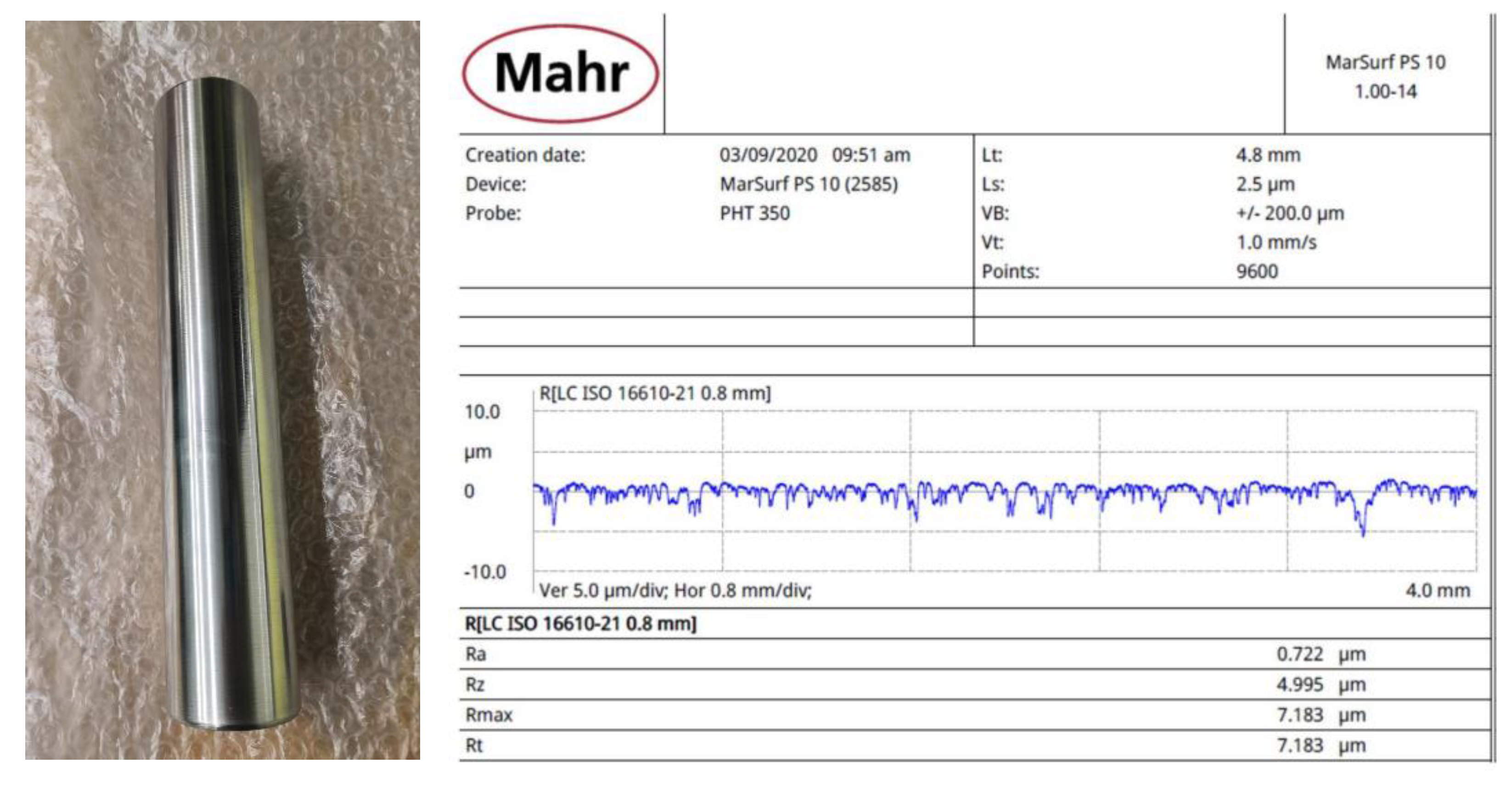
A reduced scale gas insulated prototype to mimic the full-scale GIL/GIS system was designed and constructed. This setup fulfills the requirements of cleanliness, surface smoothness of the HV electrode and the internal walls of the grounded enclosure, as well as gas tightness. Such prototype construction was very challenging. Three SF6 alternative gases were utilized in this study which are dry air; 4% C4-PFN/96% CO2 and 30% CF3I/70% CO2.
-
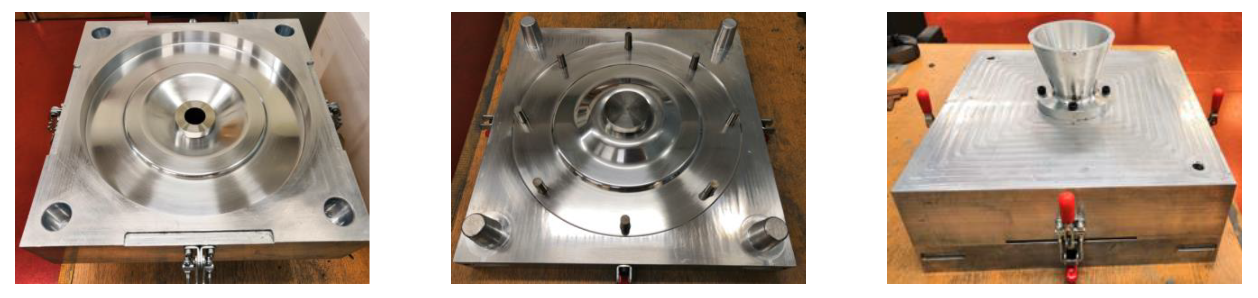
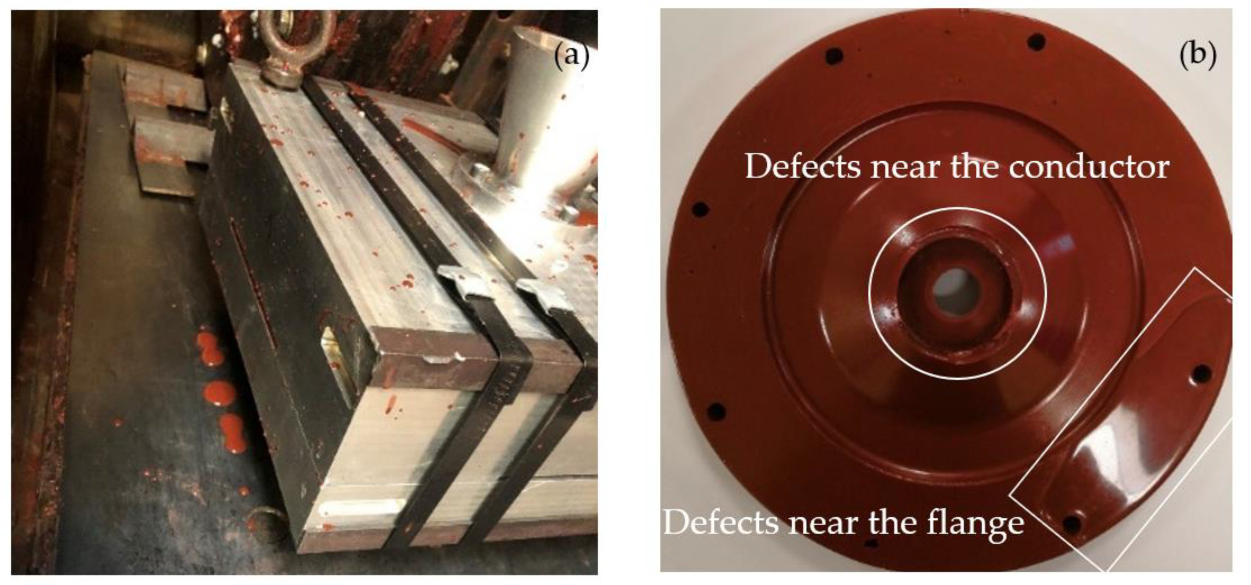
The mold of the geometrically optimized spacer was also designed and constructed. The good functionality of this mold was checked through several epoxy vacuum casting trials to get the desired final spacers without any imperfections.
-
At constant temperature and under DC voltage testing up to the maximum applicable ±123 kV where ±119 kV corresponds to ±500 kV of full-size GIL/GIS, the results showed that the optimized DC spacers made of silica and alumina filled epoxy withstood these voltage levels and did not exhibit any surface flashover. These results confirmed the findings of the electric field simulations and the effectiveness of the optimized DC spacer under uniform temperature. In addition, the utilized SF6 free alternatives are compatible with the filled epoxy materials of the DC spacers.
-
The next step of this experimental investigation is to continue the HVDC testing on the other unexplored novel types of materials and also to verify the influence of the temperature gradient.

Author Contributions

Conceptualization, N.Z., H.L., M.H. and A.R.; methodology, N.Z., H.L., M.H. and A.R.; validation, N.Z., M.H. and A.R.; formal analysis, H.L.; investigation, N.Z., H.L. and M.H.; data curation, N.Z. and H.L.; writing—original draft preparation, H.L.; writing—review and editing, N.Z., H.L., M.H. and A.R.; visualization, N.Z., H.L., M.H. and A.R.; supervision, N.Z., M.H. and A.R.; Resources, E.E. All authors have read and agreed to the published version of the manuscript.

Funding

This work is supported by the Welsh European Funding Office(WEFO) project FLEXIS: 80836.

Acknowledgments

The authors gratefully acknowledge the substantial support by Andrew Rankmore (Cardiff University) for the fabrication of the spacer mold, and Egbert Ekkel (Mekufa UK Ltd.) for the preparation of the spacers.

Conflicts of Interest

The authors declare no conflict of interest. The funders had no role in the design of the study; in the collection, analyses, or interpretation of data; in the writing of the manuscript, or in the decision to publish the results.

References

  1. Koch, H. Gas Insulated Transmission Lines (GIL); John Wiley & Sons: Chichester, UK, 2011; pp. 20–26. [Google Scholar]
  2. Koch, H. Gas Insulated Substation; John Wiley & Sons: Chichester, UK, 2014; pp. 18–49. [Google Scholar]
  3. Zebouchi, N.; Haddad, M.A. A Review on Real-Size Epoxy Cast Resin Insulators for Compact High Voltage Direct Current Gas Insulated Switchgears (GIS) and Gas Insulated Transmission Lines (GIL)—Current Achievements and Envisaged Research and Development. Energies 2020, 13, 6416. [Google Scholar] [CrossRef]
  4. General Electric. g3 -SF6 Alternative for High Voltage Applications. Available online: https://www.gegridsolutions.com/hvmv_equipment/catalog/g3/ (accessed on 1 August 2022).
  5. ABB. AirPlusTM: An Alternative to SF6 as an Insulation and Switching Medium in Electrical Switchgear. Available online: https://library.e.abb.com/public/bf0078a9a6b544279b2c5142a0cbf6fa/68-72%202m540_EN_72dpi.pdf (accessed on 1 August 2022).
  6. Sakai, T.; Furuyashiki, T.; Kato, K.; Okubo, H. Electric field analysis and Electrical insulation performance for Solid insulator in HVDC gas insulated switchgear. In Proceedings of the International Symposium on High Voltage Engineering (ISH), Pilsen, Czech Republic, 23–28 August 2015. [Google Scholar]
  7. Koo, J.; Hwang, J.; Kwon, I.; Lee, H.; Shin, W.; Lee, B. Modeling and Simulation of HVDC Epoxy Spacer for SF6 Gas Insulated System. In Proceedings of the 19th International Symposium on High Voltage Engineering, Pilsen, Czech Republic, 23–28 August 2015. [Google Scholar]
  8. Nakane, R.; Takabayashi, K.; Kato, K.; Okubo, H. Electric Field Analysis and Electrical Insulation Performance for Gas-Solid Composite Insulation in HVDC GIS. In Proceedings of the International Symposium on High Voltage Engineering (ISH), Buenos Aires, Argentina, 28 August–1 September 2017. [Google Scholar]
  9. Li, C.; Lin, C.; Yang, Y.; Zhang, B.; Liu, W.; Li, Q.; Hu, J.; He, S.; Liu, X.; He, J. Novel HVDC Spacers by Adaptively Controlling Surface Charges—Part I: Charge Transport and Control Strategy. IEEE Trans. Dielectr. Electr. Insul. 2018, 25, 1238–1247. [Google Scholar]
  10. Li, C.; Lin, C.; Yang, Y.; Zhang, B.; Liu, W.; Li, Q.; Hu, J.; He, S.; Liu, X.; He, J. Novel HVDC Spacers by Adaptively Controlling Surface Charges—Part II: Experiment. IEEE Trans. Dielectr. Electr. Insul. 2018, 25, 1248–1258. [Google Scholar]
  11. Li, C.; Lin, C.; Yang, Y.; Zhang, B.; Liu, W.; Li, Q.; Hu, J.; He, S.; Liu, X.; He, J. Novel HVDC Spacers by Adaptively Controlling Surface Charges—Part III: Industrialization Prospects. IEEE Trans. Dielectr. Electr. Insul. 2018, 25, 1259–1266. [Google Scholar]
  12. Zebouchi, N.; Li, H.; Haddad, M.A. Development of Future Compact and Eco-Friendly HVDC Gas-Insulated Systems: Shape Optimization of a DC Spacer Model and Novel Materials Investigation. Energies 2020, 13, 3288. [Google Scholar] [CrossRef]
  13. Intergovernmental Panel on Climate Change. Changes in Atmospheric Constituents and in Radiative Forcing; Intergovernmental Panel on Climate Change: Geneva, Switzerland, 2007. [Google Scholar]
  14. Zhang, B.; Li, X.; Wang, T.; Zhang, G. Surface charging characteristics of GIL model spacers under DC stress in C4F7N/CO2 gas mixture. IEEE Trans. Dielectr. Electr. Insul. 2020, 27, 597–605. [Google Scholar] [CrossRef]
  15. Katagiri, H.; Kasuya, H.; Mizoguchi, H.; Yanabu, S. Investigation of the Performance of CF3I Gas as a Possible Substitute for SF6. IEEE Trans. Dielectr. Electr. Insul. 2008, 15, 1424–1429. [Google Scholar] [CrossRef]
  16. Koch, H. Gas Insulated Lines (GIL). In Substations. CIGRE Green Books; Krieg, T., Finn, J., Eds.; Springer: Cham, Switzerland, 2019; pp. 528–531. [Google Scholar]
  17. Tu, Y.; Cheng, Y.; Wang, C.; Ai, X.; Zhou, F.; Chen, G. Insulation Characteristics of Fluoronitriles/CO2 Gas Mixture under DC Electric Field. IEEE Trans. Dielectr. Electr. Insul. 2018, 25, 1324–1331. [Google Scholar] [CrossRef]
Figure 1. Optimized shape of the spacer model for DC energization [12]. Note that the thickness of the flange is 15 mm, the thickness of the spacer at the inner conductor is 23 mm and the inclination angle is 60°; L is the length of the spacer surface.
Energies 15 08563 g001
Figure 2. Computed tangential, normal, and total electric field distributions under 131.3 kV-DC and T = 30 °C of the optimized spacer of conventional material (a) on the upper surface, (b) on the lower surface [12].
Energies 15 08563 g002
Figure 3. Schematic arrangement of the HVDC test setup and the reduced scale GIL prototype.
Energies 15 08563 g003
Figure 4. Two installed sections of the constructed GIL prototype separated by the spacer.
Energies 15 08563 g004
Figure 5. HV electrode tube (left), and surface roughness’ verification where Ra = 0.722 μm (right).
Energies 15 08563 g005
Figure 6. Mold design of the optimized spacer.
Energies 15 08563 g006
Figure 7. Mold of the optimized DC spacer.
Energies 15 08563 g007
Figure 8. Problems encountered during spacers’ fabrication. (a) Leak of the melted filled epoxy from the mold; (b) presence of imperfections near the central conductor and at some locations near the flange.
Energies 15 08563 g008
Figure 9. Spacer models: Alumina filled epoxy (top) and Silica filled epoxy (bottom).
Energies 15 08563 g009
Table 1. Dielectric strength of alternative gas mixtures compared with SF6 [14,15].
Gas MixtureDielectric Strength with Reference to SF6
Air0.3–0.4
4% C4-PFN/96% CO20.83
30% CF3I/70% CO20.75–0.8
Table 2. Tests’ results without the spacer. Note that ±119 kV is equivalent to ±500 kV and ±123 kV is the maximum applicable voltage using the DC generator (Max. ±125 kV).
Applied VoltageDry Air
10 bar (abs.)
4% C4-PFN/96% CO2
5.7 bar (abs.)
30% CF3I/70% CO2
6 bar (abs.)
+119 kVPassedPassedPassed
+123 kVPassedPassedPassed
−119 kVPassedPassedPassed
−123 kVPassedPassedPassed
Table 3. Tests’ results using silica filled epoxy.
Applied VoltageDry Air
10 bar (abs.)
4% C4-PFN/96% CO2
5.7 bar (abs.)
30% CF3I/70% CO2
6 bar (abs.)
+90 kVPassedPassedPassed
+100 kVPassedPassedPassed
+110 kVPassedPassedPassed
+119 kVPassedPassedPassed
+123 kVPassedPassedPassed
−90 kVPassedPassedPassed
−100 kVPassedPassedPassed
−110 kVPassedPassedPassed
−119 kVPassedPassedPassed
−123 kVPassedPassedPassed
Table 4. Tests’ results using alumina filled epoxy.
Applied VoltageDry Air
10 bar (abs.)
4% C4-PFN/96% CO2
5.7 bar (abs.)
30% CF3I/70% CO2
6 bar (abs.)
+90 kVPassedPassedPassed
+100 kVPassedPassedPassed
+110 kVPassedPassedPassed
+119 kVPassedPassedPassed
+123 kVPassedPassedPassed
−90 kVPassedPassedPassed
−100 kVPassedPassedPassed
−110 kVPassedPassedPassed
−119 kVPassedPassedPassed
−123 kVPassedPassedPassed
Publisher’s Note: MDPI stays neutral with regard to jurisdictional claims in published maps and institutional affiliations.

