Review

Review of Advanced Effusive Cooling for Gas Turbine Blades

1
School of Aeronautics and Astronautics, Zhejiang University, Hangzhou 310007, China
2
ZJUI Institute, Zhejiang University, Haining 314400, China
3
School of Advanced Technology, Xi’an Jiaotong-Liverpool University, Suzhou 215123, China
*
Author to whom correspondence should be addressed.
Energies 2022, 15(22), 8568; https://doi.org/10.3390/en15228568
Submission received: 8 October 2022 / Revised: 6 November 2022 / Accepted: 8 November 2022 / Published: 16 November 2022
(This article belongs to the Section J1: Heat and Mass Transfer)

Abstract

:
Turbine inlet temperature has continuously increased to improve gas turbine performance during the past few decades. Although internal convection cooling and traditional film cooling have contributed significantly to the current achievement, advanced cooling schemes are needed to minimize the coolant consumption and maximize the cooling efficiency for future gas turbines. This paper conducts a comprehensive review of advanced effusive cooling schemes for gas turbine blades. First, the background and the history of turbine blade cooling are introduced. Then, the metrics of effusive cooling efficiency are defined. Next, effusion cooling, impingement/effusion cooling, and transpiration cooling are reviewed. The flow and heat transfer mechanisms of the cooling schemes are emphasized, and the design trends of the cooling schemes are revealed. Finally, the conclusions and future research perspectives are summarized.

1. Introduction

Gas turbines have many applications such as aircraft and marine propulsion, electricity generation, and mechanical drive [1]. A sectional view of a turbojet engine is shown in Figure 1 [2]. It consists of five parts, i.e., air intake, compressor, combustor, turbine, and exhaust nozzle. The combustor liners and the first-stage turbine vanes and blades are the main hot section components [3].
In addition, the operation of gas turbines can be described by the non-ideal Brayton cycle. This indicates that the gas turbine performance relies heavily on the turbine inlet temperature (TIT). An increase of 100 °F in the TIT can bring an 8–13% improvement in the output power and an increase of 2–4% in the simple-cycle efficiency [4]. However, the rise in TIT should give consideration to the resistant temperature of turbine material, as too high a temperature will cause high-temperature corrosion [5], fatigue [6], and corrosion-fatigue failure [7]. In addition, the solid particle erosion results in severe degradation to the device parts when gas turbines are utilized in harsh environments [8]. In order to promote the TIT further and meanwhile guarantee the material safety and durability, two main approaches have been explored. One is strengthening the material thermal and mechanical properties, and the other is applying thermal protection techniques to keep the material temperature within the allowable range.
Figure 2 shows the growth of the TIT of Rolls-Royce’s civil aero-engines and the maximum allowable temperature of nickel-base superalloys [9,10,11], as well as the thermal protection techniques [12,13,14,15] in the past 70 years. Since the first utilization of internal convection cooling in the Conway turbine blades in 1962, the TIT has increased by 10 K/year, while the allowable temperature of superalloys has increased by 3 K/year. The gap between the TIT and the material’s allowable temperature has been compensated by thermal protection techniques, i.e., active cooling [12,13] and passive thermal barrier coating (TBC) [14,15]. In the early 1960s, the TIT was first higher than the superalloy allowable temperature due to the employment of internal convection cooling. In the early 1970s, a breakthrough was made that film cooling combined with internal convection cooling was applied, and in the late 1970s the TIT was 350 K higher than the material capacity. In the early 1980s, the TBC began to be used on the gas turbine vanes and could produce temperature reductions of up to about 170 K [14]. In the 21st century, to pursue high-efficiency and low-carbon gas turbines, higher TIT is required [16,17,18]. Consequently, advanced cooling schemes, TBC, and superalloys have to be developed [19]. Compared with the TBC and the superalloys, advanced cooling schemes have a shorter development cycle and higher capacity. Advanced cooling schemes might be the key to the success of future gas turbines.
Figure 3 shows a typical cooling system for modern gas turbine blades, which is achieved by both internal and external coolant flows [20]. The coolant air extracted from the compressor (often the last stage) enters the hollow blade and flows through the serpentine coolant passages to absorb heat of the blade from inside, which is the internal convection cooling. In the coolant passages, rib turbulators and pin-fins are often installed to augment internal heat transfer rates by increasing the flow turbulence and the heat transfer surface area. The coolant is finally discharged outside of the blade from holes or slots and interacts with the hot gas. As a result, the cooling layer/film is built downstream of the injection locations, shielding the blade surface from the hot mainstream. This is the film cooling. In addition, around the blade leading edge where the thermal load is highest, a perforated baffle is utilized to form high velocity jets impinging on the inside surface of blade leading edge, which is the impingement cooling.
Although the cooling requirement for modern gas turbines is achieved, the coolant quantity used to cool the turbine is significant and is about 20–30% of the total flow entering the compressor [21,22]. It is known that the coolant injected into the hot mainstream causes the mixing loss [23,24]. Moreover, the thermodynamic process is changed, as the cooling air extracted from the compressor does not enter into the combustor chamber [25]. The additional losses have a major impact on the engine performance [26,27]. Horlock et al. [26] suggested that as the TIT was increased above 1900 K, the benefit of the TIT increment to the engine cycle efficiency could be offset by the additional losses. Wilcock et al. [27] found that compared with the uncooled gas turbine, the cycle efficiency penalty of cooled gas turbine was 3.7 percent points with the current cooling technology at a TIT of 1930 K. Thus, for next-generation gas turbines, advanced cooling schemes must be developed to minimize the coolant usage and maximize the cooling efficiency.
Figure 4 shows an overview of advances in turbine blade cooling schemes from the simple convection cooling to the transpiration cooling with the improved cooling efficiency level. To make the simple convection cooling more efficient, various enhancement measures were proposed [28,29,30]. It is known that high heat transfer rate can be obtained by impinging jets [31,32,33,34,35,36]. Thus, impingement cooling is usually adopted to enhance the internal cooling performance. Even so, an inherent disadvantage of internal cooling schemes is that the external surfaces of turbine blades are directly exposed to the hot gas. Yet for effusive cooling schemes, a cooling film is built above the blade external surface, thus reducing the heat transfer into the blade [37,38,39]. An ideal film cooling design is ejecting the coolant through a tangent slot [40,41,42], but turbine blades with the continuous two-dimensional slots may suffer the structural strength loss. Thus, film cooling with discrete holes is commonly used instead. Various enhancement measures have been developed to promote the film cooling efficiency [43,44]. As the number of cooling holes increases, film cooling transits to effusion cooling [45,46]. Effusion cooling aims at providing cooling films fully covering the hot-side surfaces of a turbine blade [47,48]. Theoretically, effusion cooling becomes transpiration cooling, when the hole diameter and the hole spacing are small enough [49,50]. Practically, effusion cooling involves a perforated plate with multirow holes, while transpiration cooling involves porous materials. Transpiration cooling is believed to be the goal of turbine cooling design due to its superior cooling performance [51,52]. The investigation of transpiration cooling began in the early 1950s [53,54,55], but its commercial use in turbine blades is limited due to the concerns of structural strength and manufacturability [51,56]. Laminated cooling schemes that combined the advantages of internal and external cooling were developed in the early 1980s, such as Lamilloy [57], Transply [58], and the impingement/effusion cooling [59]. These cooling schemes are regarded as the approximation of transpiration cooling due to their high cooling efficiency, and they are also called pseudo- or quasi-transpiration cooling. Nowadays, additive manufacturing (AM) [60,61] enables the freedom of designing and fabricating porous materials, which makes transpiration cooling closer to the practical application in turbine blades [62,63].
Although in the available literature many reviews have been conducted on internal convection cooling [28,29,30,63,64], impingement cooling [31,32,33,35,36], and traditional film cooling [22,37,39,42,44], there are few reviews covering the development of advanced effusive cooling schemes for gas turbine blades. This paper aims at presenting a comprehensive review of advanced effusive cooling schemes, including effusion cooling, impingement/effusion cooling, and transpiration cooling for gas turbine blades. The flow and heat transfer mechanisms of the cooling schemes are emphasized, and the design trends of the cooling schemes are revealed.
This paper is structured as follows: the background and the history of turbine blade cooling are introduced in Section 1. The metrics of effusive cooling efficiency are given in Section 2. The advanced effusive cooling schemes, including effusion cooling, impingement/effusion cooling, and transpiration cooling are reviewed in Section 3. The conclusions and future research perspectives are summarized in Section 4.

2. Metrics of Effusive Cooling Efficiency

The heat transfer without or with effusive cooling is shown in Figure 5. Without effusive cooling (Figure 5a), the local heat flux from the mainstream to the wall q 0 is defined as
q 0 = h 0 ( T T w )
where h 0 is the heat transfer coefficient without cooling film, T is the hot mainstream temperature, and T w is the surface temperature for a conducting wall, respectively. For a constant property flow, h 0 is independent of the temperature difference ( T T w ) . Kays and Crawford [65] brought together some of the analytic approaches to calculate the convective heat transfer under certain conditions. The approximate solution of the local heat transfer coefficient for a laminar flow over an isothermal plate is given by [65]
h 0 = 0.332 λ x Pr 1 / 3 Re x 1 / 2 ,   ( Pr 0.6 )
where λ is the thermal conductivity, Pr is the Prandtl number, and Re x is the local Reynolds number. The algebraic correlation for a turbulent flow over an isothermal plate is given by [66]
h 0 = 0.0296 λ x Pr 1 / 3 Re x 4 / 5 ,   ( 0.6 Pr 60 )
With effusive cooling (Figure 5b), the local heat flux from the mainstream to the wall q f is given by [37,67]
q f = h f ( T a w T w )
where h f is the heat transfer coefficient with cooling film. T a w is the adiabatic wall temperature that represents the fluid temperature just above the surface. T a w can be normalized to the adiabatic effusive cooling efficiency η as shown by
η = T T a w T T c
where T c is the coolant temperature. Note that η varies from unity at the injection location to zero far downstream where T a w approaches the mainstream temperature because of dilution of the coolant. T w can be normalized to the overall effusive cooling efficiency φ , defined as
φ = T T w T T c
Following Sen et al. [68], the net heat flux reduction (NHFR) for the cooled turbine blade is given by
NHFR = 1 q f q 0 = 1 h f h 0 ( 1 η φ )
The correlations of heat transfer augmentation ( h f / h 0 ) for film cooling with a slot injection and a row of holes were investigated by Metzger et al. [69] and Baldauf et al. [70], respectively. For advanced effusive cooling schemes, the correlation of h f / h 0 is not derived much, while more attention is paid to the evaluation of effusive cooling efficiency.

3. Advanced Effusive Cooling Schemes

3.1. Effusion Cooling

The principle of effusion cooling is sketched in Figure 6. Coolant is discharged into the hot mainstream boundary layer through densely packed cooling holes. Owing to the insulating effect of the cooling film and the forced convection inside the cooling holes, the perforated plate temperature is lowered. It was found that significant interactions between upstream and downstream coolant jets existed in effusion cooling [71,72]. Harrington et al. [73] showed that due to the coolant superposition, the adiabatic effusion cooling efficiency was increased with the downstream location. An asymptotic “fully developed” adiabatic effusion cooling efficiency level was reached downstream of the eighth row of cooling holes. Scittore et al. [74] found that a fully developed velocity profile was reached downstream of the fifteenth row of cooling holes. In a word, the study of traditional film cooling with one or two rows of cooling holes could not provide data that were valid for effusion cooling [46].
Since effusion cooling features the coolant jets interactions, factors that influence the discrete coolant jet behavior would affect the effusion cooling performance. The primary influencing factors [73,75,76,77,78,79,80,81,82,83,84,85,86,87,88,89,90] are summarized in Table 1. Based on the investigations of discrete film cooling [22,39], it is understandable that blowing ratio (BR), density ratio (DR), hole shape, and hole angle are crucial factors. In addition, hole spacing or hole numbers and hole arrangement are important factors that affect the effusion cooling performance. Different diagnostics methods such as thermocouple thermometry, infrared thermometry (IRT) [91], pressure sensitive paint (PSP) technique [92], and liquid crystal thermometry (LCT) [93] are utilized to measure the effusion cooling performance. The referred experimental studies of effusion cooling are summarized in Table 2.
Harrington et al. [73] found that the coolant jets remained attached to the surface for BR = 0.25, while the separation of coolant jets from the surface was evident for BR ≥ 0.65. Facchini et al. [75] found that increasing the blowing ratio from 0.5 to 1.7 caused a decrease in the adiabatic effusion cooling efficiency due to the occurrence of coolant jet lift-off, while it led to a higher overall effusion cooling efficiency although the increment tended to slow down (Figure 7). This suggested that the convective heat transfer within cooling holes contributed to the overall effusion cooling efficiency. Figure 7 also showed a measurable effect of thermal conduction upstream of the first cooling row, which resulted from the high thermal conductivity of the effusion plate [79]. Wang et al. [76] studied the adiabatic effusion cooling efficiency of a flat plate at the blowing ratios from 0.4 to 2.0. The measurements showed that for BR < 0.8, the adiabatic effusion cooling efficiency increased with BR. While for BR > 0.8, it decreased with BR. Bazdidi-Tehrani and Andrews [77] found that the effect of density ratio in the range of 1.0–3.2 on the overall effusion cooling efficiency was small. The influence of density ratio on the adiabatic effusion cooling efficiency is shown in Figure 8 [78]. For the lifted-off jets (BR > 2.0), the adiabatic effusion cooling efficiency was weakly affected by DR. However, the efficiency was deeply influenced by DR under blowing ratios below 2.0.
In general, the more densely holes are packed, the closer effusion cooling is to the transpiration cooling, and the better cooling performance [79,80,81]. Gustafsson and Johansson [79] found that the cooling efficiency increased markedly with a reduction in hole spacing. Huang et al. [80] found that for 0.5 mm diameter holes, the temperature distribution was more uniform than that for 1 mm diameter holes. Murray et al. [81] found that cooling holes with close spacing had strong lateral jet interactions and could provide a near-full-coverage cooling film.
Figure 9 shows the various effusion cooling configurations with different hole arrangements and hole angles. The results in [82,83,84] showed that for simple angle holes, the staggered arrangement gave better wall protection than the inline arrangement (Figure 10). Andreini et al. [78] found that due to the improved jet attachment, inclined holes generally provided better adiabatic effusion cooling efficiency than normal holes. However, the performance of normal holes was slightly better in terms of the overall effusion cooling efficiency, for it caused low heat transfer coefficient augmentation. Moreover, Li et al. [85] showed that compared with the forward injections, effusion cooling with backward injections provided higher adiabatic cooling efficiency and heat transfer coefficient. Overall, the backward injections gave better cooling performance than the forward injections.
Regarding compound angle holes, Bashir et al. [86] showed that for holes with the same orientation angle, the staggered arrangement resulted in better cooling film coverage than the inline arrangement. Paitich et al. [87] suggested that for the staggered arrangement, the optimal compound angle was between 30° and 60°. However, for holes with opposite compound angles (Figure 9), Wang et al. [88] found that the inline arrangement gave the best adiabatic effusion cooling efficiency. Thus, when designing the effusion cooling configuration, the effects of hole arrangement and hole orientation should be considered together. Effusion cooling performances with trenched holes were also investigated in [88]. The results showed that the trenched holes always provided higher adiabatic effusion cooling efficiency than the standard holes (Figure 11). The flow patterns for various configurations were shown in Figure 12. It was found that trenched holes with opposite compound angles provided more homogenous coolant distribution than other cooling configurations. Figure 13 showed the corresponding flow structures involved in the various effusion cooling configurations. Wei et al. [89] measured the adiabatic cooling efficiency and the discharge coefficient of effusion cooling with cylindrical holes and fan-shaped holes. It was found that the fan-shaped holes had obvious advantages in comparison with the cylindrical holes. Natsui et al. [90] found that for effusion cooling with cylindrical holes, an increase in blowing ratio from 0.44 to 0.60 caused a decrease in lateral-averaged adiabatic cooling efficiency throughout most of the arrays. However, for effusion cooling with fan-shaped hoes, there was a continual increase in effectiveness as the blowing ratio was increased (Figure 14).
Currently, effusion cooling is much closer to commercial application in combustor liners [46], while its commercial use in gas turbine blades has been prevented by the manufacturing costs and the reliability concerns such as cooling holes clogged by particles [94]. Although the investigations of effusion-cooled flat plate are fundamental, more studies are needed to consider the highly turbulent, swirling, and reacting flow field in the combustor [95], and the flow characteristics in real turbine blades [96]. On the other hand, the effusion cooling efficiency should be further optimized with minimum coolant consumption [97]. This is due to the fact that modern low-emission combustion technology requires more air to burn, and hence less air is available for combustor liner cooling [98]. For turbine blade cooling, the coolant discharged into the hot mainstream also causes additional losses that are detrimental to the engine cycle efficiency.

3.2. Impingement/Effusion Cooling

Impingement/effusion cooling is also called double-wall cooling because it incorporates an impingement plate and an effusion plate. A sketch of the double-wall cooling principle is shown in Figure 15. The coolant flows through the impingement holes and impinges on the cold-side surface of the effusion plate. Then, the spent coolant convects within the internal passage between the two plates. Finally, it is discharged from the effusion holes and builds a cooling film to protect the hot-side surface of the effusion plate. A general design philosophy of the double-wall cooling is to maximize the internal heat transfer before the coolant forms the cooling film. In this sense, the enhancement measures and innovative design of internal cooling [63,64] can be borrowed in the double-wall cooling design. Figure 16 shows a conceptual design of a double-wall cooled turbine blade [99]. In the internal passage, pin or pedestal arrays are installed to enhance the internal convective cooling by increasing the wetted area and the flow turbulence. The pin or pedestal arrays also mechanically and thermally connect the two walls.
To quantify the relative contributions of the constituent parts of the double-wall cooling, Li et al. [100] performed the measurement for different cooling configurations, including pure impingement cooling, pure effusion cooling, double-wall cooling without pins, and double-wall cooling with pins (Figure 17). The results showed that for the thin effusion plate, the overall impingement cooling efficiency was 17–39% higher than the overall effusion cooling efficiency (Figure 18). Notice that the overall double-wall cooling efficiency was lower than the sum of the separate efficiency of impingement cooling and effusion cooling. This indicated that there was an interaction between them that reduced the net cooling performance [101]. Although a good knowledge of the effect of flow bled through effusion holes on the impingement heat transfer [102,103], and the effect of internal impingement jets on the adiabatic effusion cooling efficiency [104,105] has been obtained, the coupling effect of impingement cooling and effusion cooling on the double-wall cooling performance is not yet well understood.
Previous investigations of the double-wall cooling mainly focused on the influencing factors such as the relative arrangement of effusion holes and impingement holes [106,107], the crossflow in the internal passage [108,109], and the pin shape and arrangement [110,111,112]. Three typical arrangement units of effusion and impingement holes, i.e., staggered arrangement, shifted arrangement, and inline arrangement, are shown in Figure 19. Nakamata et al. [106] studied the hole arrangement effect on the double-wall cooling experimentally and found that the cooling efficiency distributions of staggered arrangement and shifted arrangement were nearly the same. Cho et al. [107] measured the heat/mass transfer distributions of double-wall cooling with different hole arrangements. It was found that the area-averaged heat/mass transfer rates on the cold-side surface of effusion plate were almost the same for the staggered and the shifted arrangements, while the heat/mass transfer distribution was more uniform for the staggered arrangement (Figure 20). The heat/mass transfer for the double-wall cooling with the staggered arrangement was a result of jet impingement, flow acceleration into effusion hole, and interaction of wall jets in the midway regions. For the in-line arrangement, most of the impinging flow was discharged directly from the effusion holes, and thus the heat/mass transfer rate was lowest.
It was known that the crossflow lowered the heat transfer rate of multiple impinging jets because it swept away the jets and delayed the impingement [33]. For double-wall cooling applied on the combustor liner or turbine blade, two types of crossflows can be encountered within the internal passage. One is an initial flow that approaches the impinging jets from upstream, and the other is formed by the spent air of the impinging jets. Rhee et al. [108] measured the heat/mass transfer characteristics of a double-wall cooling with initial crossflow. The results showed that as the flow rate of initial crossflow increased, the heat/mass transfer rates on the inside surface of the effusion plate decreased. Chen et al. [109] numerically investigated the effect of crossflow caused by the spent air on the double-wall cooling efficiency. Depending on the exhaust configuration (Figure 21), minimum, intermediate, and maximum levels of crossflow were considered. The results showed that the intermediate crossflow configuration had better performance compared with the minimum crossflow configuration, for it achieved a similar overall cooling performance with less flow bled through the effusion holes (Figure 22). The maximum crossflow configuration did not work well at low impingement jet Reynolds number. However, compared with the simple impingement cooling with maximum crossflow, all the three double-wall cooling configurations with different levels of crossflow provided higher area-averaged overall cooling efficiency.
Generally, the pin addition is beneficial to the double-wall cooling either with crossflow due to the spent air [100,106,110] or with an initial crossflow [111,112]. Nakamata et al. [106] was the first to study the effects of hole arrangement and pin addition on the double-wall cooling efficiency. The results showed that the benefit of pin addition highly depended on the pin locations. The measurements in [100] showed that the pin addition produced a gain of about 0.03 in the overall cooling efficiency (Figure 18). Kim et al. [110] found that as the number of pins increased, more pumping power was required, while the enhanced heat transfer performance could compensate for the loss of pumping power. Figure 23 showed two different configurations of pin or rib installation in the double-wall cooling with an initial crossflow, one with ribs installed on the effusion plate [111] and the other with pins of the height equal to the channel height [112]. Figure 24 showed various shapes of ribs and pins, respectively. Rhee et al. [111] found that for low flow rate of initial crossflow, the rib addition had an adverse effect on the area-averaged heat/mass transfer coefficient. While for higher flow rate of initial crossflow, the rib addition produced an increase of 10–15% in the overall heat/mass transfer. Hong et al. [112] showed that as the flow rate of initial crossflow increases, the effect of pins against the crossflow became more significant. However, the increase in the blockage effect also caused more pressure loss in the internal passage.
Recently, with the application of additive manufacturing, the innovative design of far more complicated impingement/effusion cooling schemes is evolving. Bang et al. [113] developed a new impingement/effusion cooling that consisted of three perforated plates connected by hollow cylinders (Figure 25). The new design had better cooling performance compared with the double-wall cooling with pins because the number of jet impingements and the convective heat transfer area were increased. Considering the total thickness of the impingement/effusion cooling configuration, Bang et al. [114] suggested that to achieve better thermal performance of the laminate cooling with three layers, it was preferable to set the heights of the first channel and the second channel relatively low and high, respectively. Hossain [115] designed a new double-wall cooling scheme at the leading edge of the OSU-vane by employing an unsteady sweeping jet hole to form the impingement cooling (Figure 26). The measurements showed that compared with the steady jet impingement, the sweeping jet impingement provided higher double-wall cooling efficiency.
Notice that the investigations of double-wall cooling mentioned above use the single phase air as the coolant and the cooling performance with two-phase (vapor and liquid) coolant is not covered. In fact, boiling water in small channels that are formed along turbine blades has been examined since the 1970s as a means for dissipating large amounts of heat [116]. It is suggested that effects should be made to combine the merits of microchannel flow boiling with other powerful cooling schemes, thus achieving better cooling performances [116].

3.3. Transpiration Cooling

Transpiration cooling incorporates porous materials that feature a solid matrix containing many interconnected pores [63]. A sketch of the transpiration cooling principle is shown in Figure 27. As the coolant flows through the pores of a porous material, its solid matrix is cooled by convective heat transfer. After effusing out, the coolant forms a cooling film that isolates the blade surface from the hot crossflow. Because porous media generally has a large surface area to volume ratio, the internal convection cooling is significantly enhanced. In addition, due to the large pore numbers at the surface, the coolant injection can be more uniform. As a result, the coolant air heat capacity can be fully utilized, thus achieving a better cooling efficiency than the aforementioned cooling schemes.
Figure 28 shows three typical porous material configurations, i.e., the open-cell metal foam [117], the sintered metal particles [118], and sintered woven wire mesh [119]. Transpiration cooling with the above porous materials was proved to have high efficiency, and the effects of coolant flow rate and porous media properties were investigated in the experiments [118,119,120]. Aluminum foams with different pore sizes (10–40 pores per inch) but almost identical porosity (92–94%) were tested by Hinse et al. [120]. Results showed that the pore size had negligible effects on the transpiration cooling efficiency when the porous media had a similar high porosity. The sintered porous materials with different solid matrix thermal conductivities were studied in Liu et al. [118]. The results showed that the difference in the cooling efficiency of the porous bronze plate and the porous stainless steel plate was insignificant, while on the porous bronze plate the temperature distribution was more uniform (Figure 29a). The results also showed that even a small amount of coolant usage could provide effective thermal protection, and the cooling efficiency increased with the injection ratio (Figure 29b). The sintered woven wire mesh structures made of stainless steel with different porosities (37–55%) were investigated in Xu et al. [119]. The results showed that the cooling efficiency of test samples with 37% and 46% porosities was almost identical, while for the test sample with 55% porosity, the cooling efficiency was much improved. The characteristics of the turbulent boundary layer on the porous wall in the case of transpiration cooling were investigated by the large-eddy simulation (LES) [121] and the direct numerical simulation (DNS) [122]. Xiao et al. [121] showed that the jelly roll was formed under the interaction between the hot mainstream and the coolant injection. The turbulence modification on the porous wall under various injection ratios was investigated in [122]. As shown in Figure 30, at low injection ratio, the turbulent kinetic energy (TKE) remained unchanged in the transpiration zone. However, at higher injection ratio, the mainstream separated from the wall, and the TKE was greatly enhanced because of the shear interaction between the hot gas and the coolant.
The coolant-specific heat capacity is another factor that significantly influences the transpiration cooling efficiency. Liu et al. [123] studied the transpiration cooling efficiency of a nose cone made of sintered stainless steel particles using five different coolant gases, i.e., air, nitrogen, argon, carbon dioxide, and helium. The results showed that helium, with the highest specific heat, provided the best cooling efficiency, while argon, with a specific heat just 1/10 that of helium, provided the lowest cooling efficiency at the same injection ratio. Compared with a traditional gaseous coolant, liquid water is considered a more efficient coolant because the heat of vaporization can be used as an additional cooling mechanism. Foreest et al. [124] showed that transpiration cooling using liquid water of only 0.2 g/s cooled the nose model from 2000 K to 300 K. However, using the five times mass flow of nitrogen coolant could not reduce the temperature to the same level. Using liquid water as the coolant also introduces a capillary pressure in the porous material, which can introduce water into the region containing little or no water. Huang et al. [125] proposed a self-pumping transpiration cooling design that had a double-layer porous structure. As shown in Figure 31, a sintered porous plate was covered by porous metal. While the heat was conducted through the porous cover to the sintered porous plate, the water flowed into the sintered porous by the capillary force and absorbed the heat and evaporated. The vapor finally escaped through the pores and formed the cooling film covering the external surface. The results showed that the cooling design successfully drove liquid water without any pumps and effectively cooled the heated surface [125].
Although the above research demonstrated superior transpiration cooling efficiency, the traditional porous materials for transpiration cooling could not provide the required mechanical strength in gas turbine blade cooling applications. Nowadays, additive manufacturing has the potential to fabricate stronger porous media, which revives the interest in investigating transpiration cooling. Huang et al. [126] introduced the concept of reinforcing partition walls into the additive manufactured metal porous plate (Figure 32). The results showed that the porous plate with partition walls provided a cooling performance comparable to that provided by the sintered porous plate. The partition walls had minimal effect on the transpiration cooling efficiency, while they promoted the ultimate tensile strength by 440% compared with the sintered porous plate (Figure 33).
Benefitting from the design freedom provided by the additive manufacturing, the porous media configurations can be flexibly designed. Min et al. [127] used additive manufacturing to fabricate six types of cooling configurations and evaluated their cooling efficiency. As shown in Figure 34, design (a) was the traditional film cooling with laidback fan-shaped holes, designs (b–c) were densely packed round holes similar to effusion cooling, design (d) was sphere packing similar to the sintered metal particles, design (e) was wire matrix similar to the sintered woven wire mesh, and design (f) was a blood-vessel-shaped structure. Except for the fan-shaped holes, the other five cooling structures showed the cooling efficiency peaks in the center of the surface cooled, which was due to the enhanced internal convective heat transfer. The morphological parameter analysis revealed that the major factor affecting the cooling efficiency most was the internal surface area ratio. Inspired by tree transpiration, Huang et al. [128] designed and manufactured a porous configuration with a tree-like microchannel using a metal additive manufacturing method. The results showed that the porous module successfully pulled the water to the porous surface. Inspired by the earthworm’s rough skin, Huang et al. [129] designed a porous plate with a non-smooth surface. The results showed that the cooling efficiency was maximally increased by 12% relative to the smooth surface.
In general, the leading edge of a hot component cannot be cooled efficiently. Thus, it is reasonable to distribute more coolant to the leading-edge region. The coolant allocation methods for the transpiration cooling of nose cone were studied in [130,131]. Jiang et al. [130] drilled cooling holes at the leading edge and showed that the design could effectively cool the entire specimens. Wu et al. [131] proposed a transpiration cooling design using a porous material with a non-uniform permeability. As shown in Figure 35, the permeability in the stagnation region was the highest and was smaller in downstream regions. The results showed that compared with the traditional transpiration cooling (TTC), the optimization transpiration cooling (OTC) could allocate more coolant in the stagnation region and exhibited a higher cooling efficiency (Figure 36). Nowadays, with the help of additive manufacturing technology, it is expected that the coolant allocation will be optimized in transpiration cooling.

4. Conclusions and Future Research Perspectives

In this paper, an overview of the development of advanced effusive cooling schemes for gas turbine blades is provided. The background and the history of turbine blade cooling are introduced. The effusion cooling, impingement/effusion cooling, and transpiration cooling are carefully reviewed based on the latest studies. The flow and heat transfer mechanisms of the cooling schemes are emphasized, and the design trends of the cooling schemes are revealed. The conclusions and the future research perspectives are summarized as follows:
(a)
Effusion cooling consists of multirow cooling holes and aims at providing a full coverage cooling film for the hot section components. Factors affecting film cooling efficiency are expected to influence the effusion cooling efficiency. In addition, effusion cooling features the interaction of upstream and downstream coolant jets that do not exist in discrete film cooling. Two crucial factors that affect the row-to-row interaction are hole numbers and hole arrangement. More experimental and numerical investigations are needed to quantify the effects of the numerous factors on the effusion cooling performance.
(b)
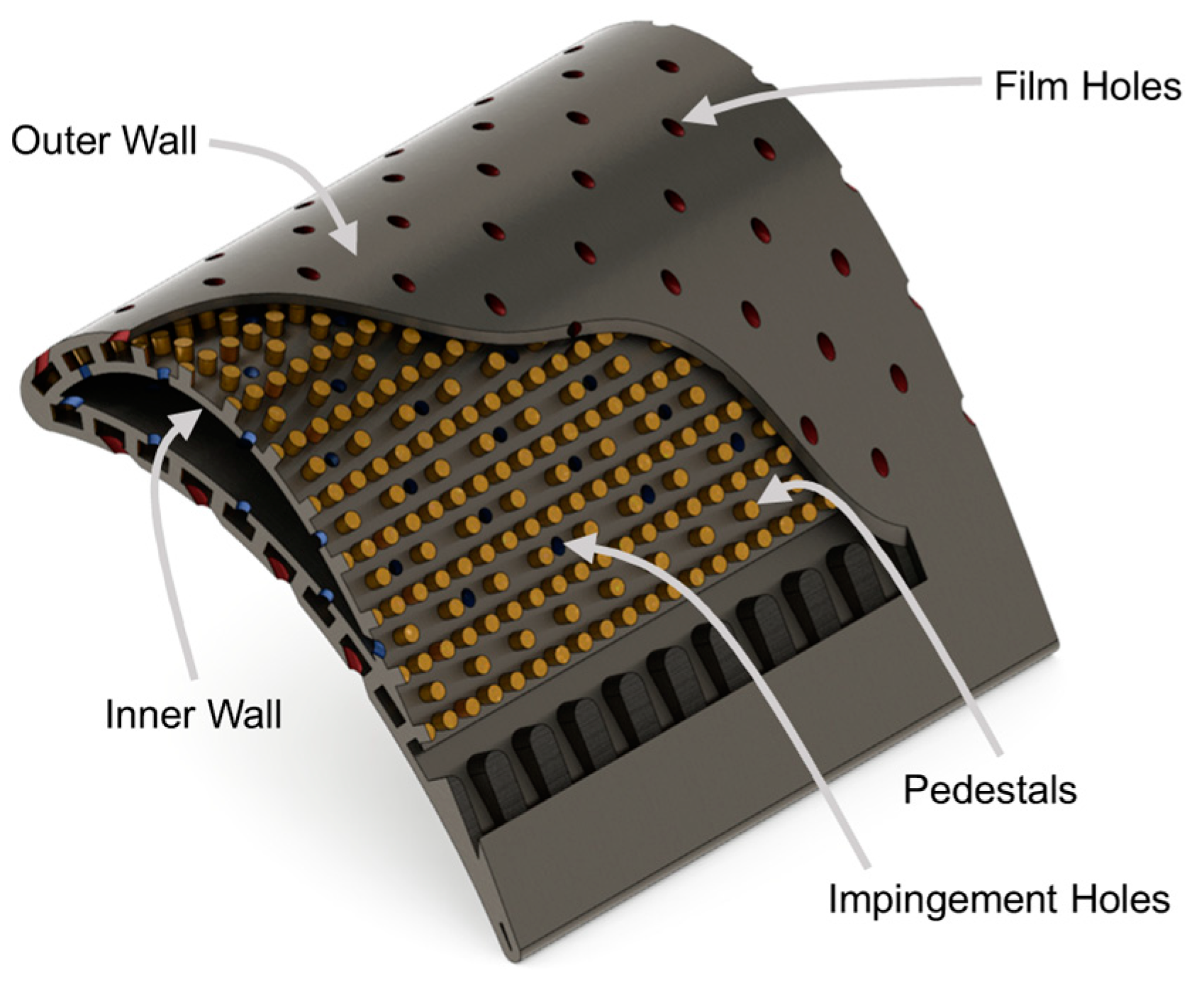
Impingement/effusion cooling incorporates double walls between which pins or pedestal arrays are usually installed to further enhance the internal heat transfer. It is suggested that other enhancement measures developed in internal cooling can be borrowed to improve the impingement/effusion cooling efficiency. In addition, to make impingement/effusion cooling schemes with internal structures more reliable, the heat transfer and mechanical stress analysis should be combined in future investigations.
(c)
Transpiration cooling has been proved to have high efficiency by both experiments and simulations. However, the mechanical strength of traditional porous materials such as metal foam, sintered metal particles, and sintered woven wire mesh limits the commercial application of transpiration cooling to gas turbine blades. Additive manufacturing technologies have provided the freedom of designing and fabricating innovative porous material configurations with elevated mechanical strength. It is expected that the optimization of coolant allocation in transpiration cooling will also benefit from the additive manufacturing.
Last but not least, although the fundamental characteristics of advanced effusive cooling schemes have been obtained using the flat plate geometry, more investigations are required to take enginelike conditions into account before these cooling methods are successfully applied in commercial gas turbine blades. It is also expected that better cooling performance would be achieved by combining the merits of powerful cooling schemes.

Author Contributions

Conceptualization, W.W.; methodology, W.W., Y.Y. and J.C.; investigation, W.W.; data curation, Y.Y. and Y.Z.; writing—original draft preparation, W.W.; writing—review and editing, Y.Y., Y.Z. and J.C.; supervision, J.C.; funding acquisition, J.C. All authors have read and agreed to the published version of the manuscript.

Funding

This research was funded by the National Natural Science Foundation of China, grant numbers 52106060 and 92152202.

Data Availability Statement

The data presented in this study are available on request from the corresponding author.

Acknowledgments

The authors acknowledge Zhejiang University, and the supports provided by the National Natural Science Foundation of China.

Conflicts of Interest

The authors declare no conflict of interest.

Nomenclature

Acronyms
TITTurbine inlet temperature
TBCThermal barrier coating
AMAdditive manufacturing
NHFRNet heat flux reduction
BRBlowing ratio
DRDensity ratio
IRTInfrared thermometry
PSPPressure sensitive paint
LCTLiquid crystal thermometry
SASimple angle
CACompound angle
LESLarge-eddy simulation
DNSDirect numerical simulation
TKETurbulent kinetic energy
Parameters
DCooling hole diameter
PLateral pitch of cooling hole
SStreamwise pitch of cooling hole
qHeat flux
hHeat transfer coefficient
TTemperature
λThermal conductivity
PrPrandtl number
ReReynolds number
ηAdiabatic cooling efficiency
φOverall cooling efficiency
FInjection ratio
Subscripts
0Without cooling film
fWith cooling film
Mainstream
cCoolant
wWall
awAdiabatic wall
Superscripts
-Lateral average
=Area average

References

  1. Soares, C. Gas Turbines: Handbook of Air, Land and Sea Applications, 2nd ed.; Elsevier: Amsterdam, The Netherlands, 2014; pp. 1–40. [Google Scholar]
  2. Wikipedia. Available online: https://en.wikipedia.org/wiki/Turbojet (accessed on 6 November 2022).
  3. Royce, R. The Jet Engine, 5th ed.; Rolls-Royce plc.: London, UK, 1996; pp. 1–64. [Google Scholar]
  4. Boyce, M.P. Gas Turbine Engineering Handbook, 4th ed.; Elsevier: Amsterdam, The Netherlands, 2011; pp. 401–425. [Google Scholar]
  5. Carter, T.J. Common failures in gas turbine blades. Eng. Fail. Anal. 2005, 12, 237–247. [Google Scholar] [CrossRef]
  6. Mishra, R.K.; Thomas, J.; Srinivasan, K.; Nandi, V.; Bhatt, R.R. Failure analysis of an un-cooled turbine blade in an aero gas turbine engine. Eng. Fail. Anal. 2017, 79, 836–844. [Google Scholar] [CrossRef]
  7. Rajabinezhad, M.; Bahrami, A.; Mousavinia, M.; Seyedi, S.J.; Taheri, P. Corrosion-fatigue failure of gas-turbine blades in an oil and gas production plant. Materials 2020, 13, 900. [Google Scholar] [CrossRef] [PubMed] [Green Version]
  8. Alqallaf, J.; Ali, N.; Teixeira, J.A.; Addali, A. Solid particle erosion behaviour and protective coatings for gas turbine compressor blades—A review. Processes 2020, 8, 984. [Google Scholar] [CrossRef]
  9. Harada, H.; Murakami, H. Design of Ni-base superalloys. In Computational Materials Design; Springer: Berlin, Heidelberg, 1999; pp. 39–70. [Google Scholar] [CrossRef]
  10. Reed, R.C. The Superalloys: Fundamentals and Applications; Cambridge University Press: Cambridge, UK, 2008; pp. 1–32. [Google Scholar]
  11. Misra, A.K.; Greenbauer-Seng, L.A. Aerospace propulsion and power materials and structures research at NASA Glenn Research Center. J. Aerosp. Eng. 2013, 26, 459–490. [Google Scholar] [CrossRef]
  12. Koff, B.L. Gas turbine technology evolution: A designers perspective. J. Propuls. Power 2004, 20, 577–595. [Google Scholar] [CrossRef]
  13. Xu, L.; Bo, S.; Hongde, Y.; Lei, W. Evolution of Rolls-Royce air-cooled turbine blades and feature analysis. Procedia Eng. 2015, 99, 1482–1491. [Google Scholar] [CrossRef] [Green Version]
  14. Miller, R.A. Thermal barrier coatings for aircraft engines: History and directions. J. Therm. Spray Technol. 1997, 6, 35–42. [Google Scholar] [CrossRef] [Green Version]
  15. Clarke, D.R.; Oechsner, M.; Padture, N.P. Thermal-barrier coatings for more efficient gas-turbine engines. MRS Bull. 2012, 37, 891–898. [Google Scholar] [CrossRef]
  16. Khosravy el_Hossaini, M. Review of the new combustion technologies in modern gas turbines. In Progress in Gas Turbine Performance; IntechOpen: London, UK, 2013; pp. 953–978. [Google Scholar] [CrossRef] [Green Version]
  17. Aminov, R.Z.; Moskalenko, A.B.; Kozhevnikov, A.I. Optimal gas turbine inlet temperature for cyclic operation. J. Phys. Conf. Ser. 2018, 1111, 012046. [Google Scholar] [CrossRef]
  18. Malina, R.; Abate, M.A.; Schlumberger, C.E.; Pineda, F.N. The Role of Sustainable Aviation Fuels in Decarbonizing Air Transport. 2022. Available online: http://hdl.handle.net/10986/38171 (accessed on 1 October 2022).
  19. Naik, S. Basic aspects of gas turbine heat transfer. In Heat Exchangers–Design, Experiment and Simulation; IntechOpen: London, UK, 2017; pp. 111–142. [Google Scholar] [CrossRef] [Green Version]
  20. Han, J.C. Recent studies in turbine blade cooling. Int. J. Rotating Mach. 2004, 10, 443–457. [Google Scholar] [CrossRef] [Green Version]
  21. Bunker, R.S. Cooling design analysis. In The Gas Turbine Handbook; NETL: Albany, NY, USA, 2006; pp. 296–308. [Google Scholar]
  22. Bogard, D.G.; Thole, K.A. Gas turbine film cooling. J. Propuls. Power 2006, 22, 249–270. [Google Scholar] [CrossRef] [Green Version]
  23. Hartsel, J. Prediction of effects of mass-transfer cooling on the blade-row efficiency of turbine airfoils. In Proceedings of the 10th Aerospace Sciences Meeting, San Diego, CA, USA, 17–19 January 1972; p. 11. [Google Scholar] [CrossRef]
  24. Denton, J.D. Loss mechanisms in turbomachines. J. Turbomach. 1993, 115, 621–656. [Google Scholar] [CrossRef]
  25. Gomes, R.A.; Araujo, M.B. On Aerothermal Effects of Film Cooling on Turbine Blades with Flow Separation; Verlag Dr. Hut: München, Germany, 2010. [Google Scholar]
  26. Horlock, J.H.; Watson, D.T.; Jones, T.V. Limitations on gas turbine performance imposed by large turbine cooling flows. J. Eng. Gas Turbines Power 2001, 123, 487–494. [Google Scholar] [CrossRef]
  27. Wilcock, R.C.; Young, J.B.; Horlock, J.H. The effect of turbine blade cooling on the cycle efficiency of gas turbine power cycles. J. Eng. Gas Turbines Power 2005, 127, 109–120. [Google Scholar] [CrossRef]
  28. Ligrani, P. Heat transfer augmentation technologies for internal cooling of turbine components of gas turbine engines. Int. J. Rotating Mach. 2013, 2013, 275653. [Google Scholar] [CrossRef]
  29. Chyu, M.K.; Siw, S.C. Recent advances of internal cooling techniques for gas turbine airfoils. J. Therm. Sci. Eng. Appl. 2013, 5, 021008. [Google Scholar] [CrossRef]
  30. Yeranee, K.; Yu, R.A.O. A review of recent studies on rotating internal cooling for gas turbine blades. Chin. J. Aeronaut. 2021, 34, 85–113. [Google Scholar] [CrossRef]
  31. Martin, H. Heat and mass transfer between impinging gas jets and solid surfaces. In Advances in Heat Transfer; Elsevier: Amsterdam, The Netherlands, 1977; Volume 13, pp. 1–60. [Google Scholar] [CrossRef]
  32. Zuckerman, N.; Lior, N. Jet impingement heat transfer: Physics, correlations, and numerical modeling. Adv. Heat Transf. 2006, 39, 565–631. [Google Scholar] [CrossRef]
  33. Weigand, B.; Spring, S. Multiple jet impingement—A review. In Proceedings of the International Symposium on Heat Transfer in Gas Turbine Systems, Antalya, Turkey, 9–14 August 2009; Begel House Inc.: Danbury, CT, USA, 2009. [Google Scholar] [CrossRef]
  34. Maghrabie, H.M. Heat transfer intensification of jet impingement using exciting jets—A comprehensive review. Renew. Sustain. Energy Rev. 2021, 139, 110684. [Google Scholar] [CrossRef]
  35. Hussain, L.; Khan, M.M.; Masud, M.; Ahmed, F.; Rehman, Z.; Amanowicz, Ł.; Rajski, K. Heat Transfer Augmentation through Different Jet Impingement Techniques: A State-of-the-Art Review. Energies 2021, 14, 6458. [Google Scholar] [CrossRef]
  36. Dutta, S.; Singh, P. Opportunities in Jet-Impingement Cooling for Gas-Turbine Engines. Energies 2021, 14, 6587. [Google Scholar] [CrossRef]
  37. Goldstein, R.J. Film cooling. In Advances in Heat Transfer; Elsevier: Amsterdam, The Netherlands, 1971; Volume 7, pp. 321–379. [Google Scholar] [CrossRef]
  38. Han, J.C. Fundamental gas turbine heat transfer. Journal of thermal science and engineering applications. J. Thermal Sci. Eng. Appl. 2013, 5, 021007. [Google Scholar] [CrossRef]
  39. Acharya, S.; Kanani, Y. Advances in film cooling heat transfer. In Advances in Heat Transfer; Elsevier: Amsterdam, The Netherlands, 2017; Volume 49, pp. 91–156. [Google Scholar] [CrossRef]
  40. Seban, R.A. Heat transfer and effectiveness for a turbulent boundary layer with tangential fluid injection. J. Heat Transf. 1960, 82, 303–312. [Google Scholar] [CrossRef]
  41. Goldstein, R.J.; Eckert, E.R.G.; Tsou, F.K.; Haji-Sheikh, A. Film cooling with air and helium injection through a rearward-facing slot into a supersonic air flow. AIAA J. 1966, 4, 981–985. [Google Scholar] [CrossRef]
  42. Jia, R.; Sunden, B.; Miron, P.; Léger, B. A numerical and experimental investigation of the slot film-cooling jet with various angles. J. Turbomach. 2005, 127, 635–645. [Google Scholar] [CrossRef]
  43. Bunker, R.S. A review of shaped hole turbine film-cooling technology. J. Heat Transf. 2005, 127, 441–453. [Google Scholar] [CrossRef]
  44. Zhang, J.; Zhang, S.; Chunhua, W.A.N.G.; Xiaoming, T.A.N. Recent advances in film cooling enhancement: A review. Chin. J. Aeronaut. 2020, 33, 1119–1136. [Google Scholar] [CrossRef]
  45. Cerri, G.; Giovannelli, A.; Battisti, L.; Fedrizzi, R. Advances in effusive cooling techniques of gas turbines. Appl. Therm. Eng. 2007, 27, 692–698. [Google Scholar] [CrossRef]
  46. Krewinkel, R. A review of gas turbine effusion cooling studies. Int. J. Heat Mass Transf. 2013, 66, 706–722. [Google Scholar] [CrossRef]
  47. Sellers, J.P., Jr. Gaseous film cooling with multiple injection stations. AIAA J. 1963, 1, 2154–2156. [Google Scholar] [CrossRef]
  48. Mayle, R.E.; Camarata, F.J. Multihole cooling film effectiveness and heat transfer. J. Heat Transf. 1975, 97, 534–538. [Google Scholar] [CrossRef]
  49. Grootenhuis, P. The mechanism and application of effusion cooling. Aeronaut. J. 1959, 63, 73–89. [Google Scholar] [CrossRef]
  50. Wadia, A.R. Advanced combustor liner cooling technology for gas turbines. Def. Sci. J. 1988, 38, 363–380. [Google Scholar] [CrossRef]
  51. Bunker, R.S. Evolution of turbine cooling. In Turbo Expo: Power for Land, Sea, and Air; American Society of Mechanical Engineers: New York, NY, USA, 2017; Volume 50770, p. V001T51A001. [Google Scholar] [CrossRef]
  52. Filinov, E.P.; Kuz’michev, V.S.; Yu Tkachenko, A.; Ostapyuk, Y.; Krupenich, I.N. Estimation of cooling flow rate for conceptual design stage of a gas turbine engine. Proc. Inst. Mech. Eng. Part A J. Power Energy 2021, 235, 2014–2021. [Google Scholar] [CrossRef]
  53. Duwez, P.; Wheeler, H.L., Jr. Experimental study of cooling by injection of a fluid through a porous material. J. Aeronaut. Sci. 1948, 15, 509–521. [Google Scholar] [CrossRef]
  54. Eckert, E.R.G.; Esgar, J.B. Survey of Advantages and Problems Associated with Transpiration Cooling and Film Cooling of Gas-Turbine Blades (No. NACA-RM-E50K15). 1951. Available online: https://ntrs.nasa.gov/citations/19930086539 (accessed on 1 October 2022).
  55. Eckert, E.R.G.; Livingood, J.N. Comparison of Effectiveness of Convection-, Transpiration-, and Film-Cooling Methods with Air as Coolant (Vol. 1182). National Advisory Committee for Aeronautics. 1954. Available online: https://ntrs.nasa.gov/citations/19930092205 (accessed on 1 October 2022).
  56. Zhang, S.; Li, X.; Zuo, J.; Qin, J.; Cheng, K.; Feng, Y.; Bao, W. Research progress on active thermal protection for hypersonic vehicles. Prog. Aerosp. Sci. 2020, 119, 100646. [Google Scholar] [CrossRef]
  57. Nealy, D.A.; Reider, S.B. Evaluation of laminated porous wall materials for combustor liner cooling. J. Eng. Power 1980, 102, 268–276. [Google Scholar] [CrossRef]
  58. Wassell, A.B.; Bhangu, J.K. The development and application of improved combustor wall cooling techniques. In Turbo Expo: Power for Land, Sea, and Air; American Society of Mechanical Engineers: New York, NY, USA, 1980; Volume 79658, p. V01AT01A066. [Google Scholar] [CrossRef] [Green Version]
  59. Hollworth, B.R.; Dagan, L. Arrays of impinging jets with spent fluid removal through vent holes on the target surface—Part 1: Average heat transfer. J. Eng. Power 1980, 102, 994–999. [Google Scholar] [CrossRef]
  60. Frazier, W.E. Metal additive manufacturing: A review. J. Mater. Eng. Perform. 2014, 23, 1917–1928. [Google Scholar] [CrossRef]
  61. Vafadar, A.; Guzzomi, F.; Rassau, A.; Hayward, K. Advances in metal additive manufacturing: A review of common processes, industrial applications, and current challenges. Appl. Sci. 2021, 11, 1213. [Google Scholar] [CrossRef]
  62. Guddati, S.; Kiran, A.; Leavy, M.; Ramakrishna, S. Recent advancements in additive manufacturing technologies for porous material applications. Int. J. Adv. Manuf. Technol. 2019, 105, 193–215. [Google Scholar] [CrossRef]
  63. Kaur, I.; Singh, P. State-of-the-art in heat exchanger additive manufacturing. Int. J. Heat Mass Transf. 2021, 178, 121600. [Google Scholar] [CrossRef]
  64. Kaur, I.; Singh, P. Critical evaluation of additively manufactured metal lattices for viability in advanced heat exchangers. Int. J. Heat Mass Transf. 2021, 168, 120858. [Google Scholar] [CrossRef]
  65. Kays, W.M.; Crawford, M.E. Convective Heat and Mass Transfer, 3rd ed.; McGraw Hill: New York, NY, USA, 1993; pp. 159–191. [Google Scholar]
  66. Incropera, F.P.; Dewitt, D.P.; Bergman, T.L.; Lavine, A.S. Fundamentals of Heat and Mass Transfer, 6th ed.; John Wiley and Sons: Hoboken, NJ, USA, 2007; pp. 405–414. [Google Scholar]
  67. Eckert, E.R.G. Analysis of film cooling and full-coverage film cooling of gas turbine blades. J. Eng. Gas Turbines Power 1984, 106, 206–213. [Google Scholar] [CrossRef]
  68. Sen, B.; Schmidt, D.L.; Bogard, D.G. Film cooling with compound angle holes: Heat transfer. J. Turbomach. 1996, 118, 800–806. [Google Scholar] [CrossRef]
  69. Metzger, D.E.; Carper, H.J.; Swank, L.R. Heat transfer with film cooling near nontangential injection slots. J. Eng. Power 1968, 90, 157–162. [Google Scholar] [CrossRef]
  70. Baldauf, S.; Scheurlen, M.; Schulz, A.; Wittig, S. Heat Flux Reduction From Film Cooling and Correlation of Heat Transfer Coefficients From Thermographic Measurements at Enginelike Conditions. J. Turbomach. 2002, 124, 699–709. [Google Scholar] [CrossRef]
  71. Wang, L.; Li, X.; Ren, J.; Jiang, H. The interaction between upstream and downstream film cooling rows in flow field and heat transfer. Int. J. Therm. Sci. 2020, 149, 106176. [Google Scholar] [CrossRef]
  72. Jiang, Y.; Murray, A.V.; Ireland, P.T.; di Mare, L. Coolant Jets Interaction in Effusion Cooling System: Experimental and Numerical Study. J. Turbomach. 2020, 142, 091007. [Google Scholar] [CrossRef]
  73. Harrington, M.K.; McWaters, M.A.; Bogard, D.G.; Lemmon, C.A.; Thole, K.A. Full-coverage film cooling with short normal injection holes. J. Turbomach. 2001, 123, 798–805. [Google Scholar] [CrossRef]
  74. Scrittore, J.J.; Thole, K.A.; Burd, S.W. Investigation of velocity profiles for effusion cooling of a combustor liner. J. Turbomach. 2007, 129, 518–526. [Google Scholar] [CrossRef]
  75. Facchini, B.; Tarchi, L.; Toni, L.; Ceccherini, A. Adiabatic and overall effectiveness measurements of an effusion cooling array for turbine endwall application. J. Turbomach. 2010, 132, 041008. [Google Scholar] [CrossRef]
  76. Wang, G.; Ledezma, G.; DeLancey, J.; Wang, A. Experimental Study of Effusion Cooling with Pressure-Sensitive Paint. J. Eng. Gas Turbines Power 2017, 139, 051601. [Google Scholar] [CrossRef]
  77. Bazdidi-Tehrani, F.; Andrews, G.E. Full-coverage discrete hole film cooling: Investigation of the effect of variable density ratio. J. Eng. Gas Turbines Power. 1994, 116, 587–596. [Google Scholar] [CrossRef]
  78. Andreini, A.; Facchini, B.; Picchi, A.; Tarchi, L.; Turrini, F. Experimental and theoretical investigation of thermal effectiveness in multiperforated plates for combustor liner effusion cooling. J. Turbomach. 2014, 136, 091003. [Google Scholar] [CrossRef]
  79. Gustafsson, K.B.; Johansson, T.G. An experimental study of surface temperature distribution on effusion-cooled plates. J. Eng. Gas Turbines Power 2001, 123, 308–316. [Google Scholar] [CrossRef]
  80. Huang, Z.; Xiong, Y.B.; Liu, Y.Q.; Jiang, P.X.; Zhu, Y.H. Experimental investigation of full-coverage effusion cooling through perforated flat plates. Appl. Therm. Eng. 2015, 76, 76–85. [Google Scholar] [CrossRef]
  81. Murray, A.V.; Ireland, P.T.; Wong, T.H.; Tang, S.W.; Rawlinson, A.J. High Resolution Experimental and Computational Methods for Modelling Multiple Row Effusion Cooling Performance. Int. J. Turbomach. Propuls. Power 2018, 3, 4. [Google Scholar] [CrossRef] [Green Version]
  82. Metzger, D.E.; Takeuchi, D.I.; Kuenstler, P.A. Effectiveness and heat transfer with full-coverage film cooling. J. Eng. Power 1973, 95, 180–184. [Google Scholar] [CrossRef]
  83. Yuen, C.H.N.; Martinez-Botas, R.F. Film cooling characteristics of rows of round holes at various streamwise angles in a crossflow: Part I. Effectiveness. Int. J. Heat Mass Transf. 2005, 48, 4995–5016. [Google Scholar] [CrossRef]
  84. Ahmed, S.; Ramakrishnan, K.R.; Ekkad, S.V. Overall Cooling Effectiveness of Effusion Cooled Can Combustor Liner under Reacting and Non-Reacting Conditions. J. Therm. Sci. Eng. Appl. 2022, 14, 021009. [Google Scholar] [CrossRef]
  85. Li, W.; Lu, X.; Li, X.; Ren, J.; Jiang, H. Wall thickness and injection direction effects on flat plate full-coverage film cooling arrays: Adiabatic film effectiveness and heat transfer coefficient. Int. J. Therm. Sci. 2019, 136, 172–181. [Google Scholar] [CrossRef]
  86. Bashir, M.H.; Shiau, C.C.; Han, J.C. Film cooling effectiveness for three-row compound angle hole design on flat plate using PSP technique. Int. J. Heat Mass Transf. 2017, 115, 918–929. [Google Scholar] [CrossRef]
  87. Paitich, L.C.; Richer, P.; Jodoin, B.; Pyo, Y.; Yun, S.; Hong, Z. Directional Effects of Effusion Cooling on the Cooling Film Effectiveness. AIAA J. 2022, 60, 423–434. [Google Scholar] [CrossRef]
  88. Wang, W.; Cui, J.H.; Qu, S.X. Effects of hole arrangement and trenched hole on multirow film cooling. AIP Adv. 2022, 12, 045205. [Google Scholar] [CrossRef]
  89. Wei, H.; Zu, Y.Q.; Ai, J.L.; Ding, L. Experimental study on the full-coverage film cooling of fan-shaped holes with a constant exit width. Int. J. Heat Mass Transf. 2019, 140, 379–398. [Google Scholar] [CrossRef]
  90. Natsui, G.; Little, Z.; Kapat, J.S.; Dees, J.E. Adiabatic film cooling effectiveness measurements throughout multirow film cooling arrays. J. Turbomach. 2017, 139, 101008. [Google Scholar] [CrossRef]
  91. Usamentiaga, R.; Venegas, P.; Guerediaga, J.; Vega, L.; Molleda, J.; Bulnes, F.G. Infrared thermography for temperature measurement and non-destructive testing. Sensors 2014, 14, 12305–12348. [Google Scholar] [CrossRef] [Green Version]
  92. Han, J.C.; Rallabandi, A. Turbine blade film cooling using PSP technique. Front. Heat Mass Transf. 2010, 1, 013001. [Google Scholar] [CrossRef]
  93. Ekkad, S.V.; Singh, P. Liquid Crystal Thermography in Gas Turbine Heat Transfer: A Review on Measurement Techniques and Recent Investigations. Crystals 2021, 11, 1332. [Google Scholar] [CrossRef]
  94. Tian, K.; Tang, Z.; Wang, J.; Vujanović, M.; Zeng, M.; Wang, Q. Numerical investigations of film cooling and particle impact on the blade leading edge. Energies 2021, 14, 1102. [Google Scholar] [CrossRef]
  95. Aumeier, T.; Behrendt, T. Application of an Aerothermal Model for Effusion Cooling Systems and Finite Rate Chemistry in Aeroengine Combustors. Turbul. Heat Mass Transf. 2015, 8, 851–854. [Google Scholar]
  96. Dunn, M.G. Convective heat transfer and aerodynamics in axial flow turbines. J. Turbomach. 2001, 123, 637–686. [Google Scholar] [CrossRef]
  97. Zhang, G.; Rui, Z.H.U.; Gongnan, X.I.E.; Shulei, L.I.; Sunde, B. Optimization of cooling structures in gas turbines: A review. Chin. J. Aeronaut. 2022, 35, 18–46. [Google Scholar] [CrossRef]
  98. Liu, Y.; Sun, X.; Sethi, V.; Nalianda, D.; Li, Y.G.; Wang, L. Review of modern low emissions combustion technologies for aero gas turbine engines. Prog. Aerosp. Sci. 2017, 94, 12–45. [Google Scholar] [CrossRef] [Green Version]
  99. Murray, A.V.; Ireland, P.T.; Romero, E. Experimental and Computational Methods for the Evaluation of Double-Wall, Effusion Cooling Systems. J. Turbomach. 2020, 142, 111003. [Google Scholar] [CrossRef]
  100. Li, W.; Lu, X.; Li, X.; Ren, J.; Jiang, H. On improving full-coverage effusion cooling efficiency by varying cooling arrangements and wall thickness in double wall cooling application. J. Heat Transf. 2019, 141, 042201. [Google Scholar] [CrossRef]
  101. Andrews, G.E.; Asere, A.A.; Hussain, C.I.; Mkpadi, M.C.; Nazari, A. Impingement/effusion cooling: Overall wall heat transfer. In Turbo Expo: Power for Land, Sea, and Air; American Society of Mechanical Engineers: New York, NY, USA, 1988; Volume 79214, p. V004T09A036. [Google Scholar] [CrossRef] [Green Version]
  102. Metzger, D.E.; Bunker, R.S. Local heat transfer in internally cooled turbine airfoil leading edge regions: Part II—Impingement cooling with film coolant extraction. J. Turbomach. 1990, 112, 451–458. [Google Scholar] [CrossRef]
  103. Zhou, J.; Wang, X.; Li, J. Influences of effusion hole diameter on impingement/effusion cooling performance at turbine blade leading edge. Int. J. Heat Mass Transf. 2019, 134, 1101–1118. [Google Scholar] [CrossRef]
  104. Rogers, N.; Ren, Z.; Buzzard, W.; Sweeney, B.; Tinker, N.; Ligrani, P.; Hollingsworth, K.; Liberatore, F.; Patel, R.; Ho, S.; et al. Effects of double wall cooling configuration and conditions on performance of full-coverage effusion cooling. J. Turbomach. 2017, 139, 051009. [Google Scholar] [CrossRef]
  105. Ligrani, P.; Ren, Z.; Liberatore, F.; Patel, R.; Srinivasan, R.; Ho, Y.H. Double wall cooling of a full-coverage effusion plate, including internal impingement array cooling. J. Eng. Gas Turbines Power 2018, 140, 051901. [Google Scholar] [CrossRef]
  106. Nakamata, C.; Mimura, F.; Matsushita, M.; Yamane, T.; Fukuyama, Y.; Yoshida, T. Local cooling effectiveness distribution of an integrated impingement and pin fin cooling configuration. In Turbo Expo: Power for Land, Sea, and Air; American Society of Mechanical Engineers: New York, NY, USA, 2007; Volume 47934, pp. 23–34. [Google Scholar] [CrossRef]
  107. Cho, H.H.; Rhee, D.H.; Goldstein, R.J. Effects of hole arrangements on local heat/mass transfer for impingement/effusion cooling with small hole spacing. J. Turbomach. 2008, 130, 041003. [Google Scholar] [CrossRef]
  108. Rhee, D.H.; Choi, J.H.; Cho, H.H. Flow and heat (mass) transfer characteristics in an impingement/effusion cooling system with crossflow. J. Turbomach. 2003, 125, 74–82. [Google Scholar] [CrossRef]
  109. Chen, G.; Liu, Y.; Rao, Y.; He, J.; Qu, Y. Numerical investigation on conjugate heat transfer of impingement/effusion double-wall cooling with different crossflow schemes. Appl. Therm. Eng. 2019, 155, 515–524. [Google Scholar] [CrossRef]
  110. Kim, S.H.; Ahn, K.H.; Park, J.S.; Jung, E.Y.; Hwang, K.Y.; Cho, H.H. Local heat and mass transfer measurements for multi-layered impingement/effusion cooling: Effects of pin spacing on the impingement and effusion plate. Int. J. Heat Mass Transf. 2017, 105, 712–722. [Google Scholar] [CrossRef]
  111. Rhee, D.H.; Nam, Y.W.; Cho, H.H. Local heat/mass transfer with various rib arrangements in impingement/effusion cooling system with crossflow. J. Turbomach. 2004, 126, 615–626. [Google Scholar] [CrossRef]
  112. Hong, S.K.; Rhee, D.H.; Cho, H.H. Effects of fin shapes and arrangements on heat transfer for impingement/effusion cooling with crossflow. J. Heat Transf. 2007, 129, 1697–1707. [Google Scholar] [CrossRef]
  113. Bang, M.; Kim, S.; Choi, S.; Sohn, H.S.; Cho, H.H. Impingement/effusion cooling with a hollow cylinder structure for additive manufacturing. Int. J. Heat Mass Transf. 2020, 155, 119786. [Google Scholar] [CrossRef]
  114. Bang, M.; Kim, S.; Park, H.S.; Kim, T.; Rhee, D.H.; Cho, H.H. Impingement/effusion cooling with a hollow cylinder structure for additive manufacturing: Effect of channel gap height. Int. J. Heat Mass Transf. 2021, 175, 121420. [Google Scholar] [CrossRef]
  115. Hossain, M.A.; Ameri, A.; Gregory, J.W.; Bons, J.P. Experimental investigation of innovative cooling schemes on an additively manufactured engine scale turbine nozzle guide vane. J. Turbomach. 2021, 143, 051004. [Google Scholar] [CrossRef]
  116. Mudawar, I. Two-phase microchannel heat sinks: Theory, applications, and limitations. J. Electron. Packag. 2011, 133, 041002. [Google Scholar] [CrossRef]
  117. Boomsma, K.; Poulikakos, D.; Zwick, F. Metal foams as compact high performance heat exchangers. Mech. Mater. 2003, 35, 1161–1176. [Google Scholar] [CrossRef]
  118. Liu, Y.Q.; Jiang, P.X.; Xiong, Y.B.; Wang, Y.P. Experimental and numerical investigation of transpiration cooling for sintered porous flat plates. Appl. Therm. Eng. 2013, 50, 997–1007. [Google Scholar] [CrossRef]
  119. Xu, G.; Liu, Y.; Luo, X.; Ma, J.; Li, H. Experimental investigation of transpiration cooling for sintered woven wire mesh structures. Int. J. Heat Mass Transf. 2015, 91, 898–907. [Google Scholar] [CrossRef]
  120. Hinse, M.; Yildiz, K.; Richer, P.; Jodoin, B.; Bourmand, M.; Yun, S.; Hong, Z. Numerical and Experimental Studies of Transpiration Cooling Film Effectiveness over Porous Materials. J. Thermophys. Heat Transf. 2022, 36, 1–15. [Google Scholar] [CrossRef]
  121. Xiao, X.; Zhao, G.; Zhou, W.; Martynenko, S. Large-eddy simulation of transpiration cooling in turbulent channel with porous wall. Appl. Therm. Eng. 2018, 145, 618–629. [Google Scholar] [CrossRef]
  122. Christopher, N.; Peter, J.M.; Kloker, M.J.; Hickey, J.P. DNS of turbulent flat-plate flow with transpiration cooling. Int. J. Heat Mass Transf. 2020, 157, 119972. [Google Scholar] [CrossRef]
  123. Liu, Y.Q.; Jiang, P.X.; Jin, S.S.; Sun, J.G. Transpiration cooling of a nose cone by various foreign gases. Int. J. Heat Mass Transf. 2010, 53, 5364–5372. [Google Scholar] [CrossRef]
  124. van Foreest, A.; Sippel, M.; Gülhan, A.; Esser, B.; Ambrosius, B.A.C.; Sudmeijer, K. Transpiration cooling using liquid water. J. Thermophys. Heat Transf. 2009, 23, 693–702. [Google Scholar] [CrossRef]
  125. Huang, G.; Liao, Z.; Xu, R.; Zhu, Y.; Jiang, P.X. Self-pumping transpiration cooling with a protective porous armor. Appl. Therm. Eng. 2020, 164, 114485. [Google Scholar] [CrossRef]
  126. Huang, G.; Min, Z.; Yang, L.; Jiang, P.X.; Chyu, M. Transpiration cooling for additive manufactured porous plates with partition walls. Int. J. Heat Mass Transf. 2018, 124, 1076–1087. [Google Scholar] [CrossRef]
  127. Min, Z.; Huang, G.; Parbat, S.N.; Yang, L.; Chyu, M.K. Experimental investigation on additively manufactured transpiration and film cooling structures. J. Turbomach. 2019, 141, 031009. [Google Scholar] [CrossRef]
  128. Huang, G.; Zhu, Y.; Liao, Z.; Xu, R.; Jiang, P.X. Biomimetic self-pumping transpiration cooling for additive manufactured porous module with tree-like micro-channel. Int. J. Heat Mass Transf. 2019, 131, 403–410. [Google Scholar] [CrossRef]
  129. Huang, G.; Zhu, Y.; Liao, Z.Y.; Huang, Z.; Jiang, P.X. Transpiration cooling with bio-inspired structured surfaces. Bioinspiration Biomim. 2020, 15, 036016. [Google Scholar] [CrossRef]
  130. Jiang, P.X.; Huang, G.; Zhu, Y.; Liao, Z.; Huang, Z. Experimental investigation of combined transpiration and film cooling for sintered metal porous struts. Int. J. Heat Mass Transf. 2017, 108, 232–243. [Google Scholar] [CrossRef]
  131. Wu, N.; Wang, J.; He, F.; Chen, L.; Ai, B. Optimization transpiration cooling of nose cone with non-uniform permeability. Int. J. Heat Mass Transf. 2018, 127, 882–891. [Google Scholar] [CrossRef]
Figure 1. Sectional view of a turbojet engine. Adapted with permission from [2]. Licensed under a Creative Commons Attribution (CC BY) license.
Energies 15 08568 g001
Figure 2. Evolution of the TIT of Rolls-Royce’s civil aero-engines, the maximum allowable temperature of nickel-base superalloys, and the thermal protection techniques. Data collected from [9,10,11].
Energies 15 08568 g002
Figure 3. Typical cooling system for modern gas turbine blades. Adapted with permission from [20]. Licensed under a Creative Commons Attribution (CC BY) license.
Energies 15 08568 g003
Figure 4. Overview of advances in turbine blade cooling schemes.
Energies 15 08568 g004
Figure 5. Schematics of heat transfer without or with effusive cooling.
Energies 15 08568 g005
Figure 6. Schematic diagram of effusion cooling principle.
Energies 15 08568 g006
Figure 7. Effects of BR on the lateral-averaged adiabatic effusion cooling efficiency and the lateral-averaged overall effusion cooling efficiency. Reprinted with permission from [75]. Copyright 2010 ASME.
Energies 15 08568 g007
Figure 8. Effects of DR and BR on the lateral-averaged adiabatic effusion cooling efficiency. Reprinted with permission from [78]. Copyright 2014 ASME.
Energies 15 08568 g008
Figure 9. Effusion cooling configurations with different hole arrangements and hole angles.
Energies 15 08568 g009
Figure 10. Lateral-averaged overall effusion cooling efficiency of the combustor liner: (a) inline arrangement and (b) staggered arrangement. Reprinted with permission from [84]. Copyright 2021 ASME.
Energies 15 08568 g010
Figure 11. Adiabatic cooling efficiency for various effusion cooling configurations. Adapted with permission from [88]. Licensed under a Creative Commons Attribution (CC BY) license.
Energies 15 08568 g011
Figure 12. Streamlines colored by the dimensionless temperature for various effusion cooling configurations. Reprinted with permission from [88]. Licensed under a Creative Commons Attribution (CC BY) license.
Energies 15 08568 g012
Figure 13. Dimensionless temperature contour overlaid with streamlines in the specific cross sections of various effusion cooling configurations. Adapted with permission from [88]. Licensed under a Creative Commons Attribution (CC BY) license.
Energies 15 08568 g013
Figure 14. Lateral-averaged adiabatic effusion cooling efficiency with cylindrical holes and fan-shaped holes under various blowing ratios. Adapted with permission from [90]. Copyright 2017 ASME.
Energies 15 08568 g014
Figure 15. Schematic diagram of double-wall cooling principle.
Energies 15 08568 g015
Figure 16. A conceptual design of double-wall cooled turbine blade. Reprinted with permission from [99]. Copyright 2020 ASME.
Energies 15 08568 g016
Figure 17. Various cooling configurations: (a) pure impingement cooling, (b) pure effusion cooling, (c) double-wall cooling, and (d) double-wall cooling with pins. Adapted with permission from [100]. Copyright 2019 ASME.
Energies 15 08568 g017
Figure 18. Comparisons of the overall cooling efficiency of various cooling configurations. Reprinted with permission from [100]. Copyright 2019 ASME.
Energies 15 08568 g018
Figure 19. Three typical arrangement units of effusion and impingement holes.
Energies 15 08568 g019
Figure 20. Nusselt number distributions for various hole arrangements. Reprinted with permission from [107]. Copyright 2008 ASME.
Energies 15 08568 g020
Figure 21. Double-wall cooling configurations with different levels of crossflow. Adapted with permission from [109]. Copyright 2019 Elsevier.
Energies 15 08568 g021
Figure 22. Comparisons of the area-averaged overall double-wall cooling efficiency and the area-averaged overall cooling efficiency ratios related to the pure impingement cooling. Reprinted with permission from [109]. Copyright 2019 Elsevier.
Energies 15 08568 g022
Figure 23. Double-wall cooling with initial crossflow: (a) ribs installed on the effusion plate (reprinted with permission from [111], copyright 2004 ASME) and (b) pins installed between impingement and effusion plates (reprinted with permission from [112], copyright 2007 ASME).
Energies 15 08568 g023
Figure 24. (ae) Various rib shapes installed on the effusion plate (reprinted with permission from [111], copyright 2004 ASME) and (fj) various pin shapes installed between impingement and effusion plates (adapted with permission from [112], copyright 2007 ASME).
Energies 15 08568 g024
Figure 25. Impingement/effusion cooling created by three perforated plates with hollow-cylinder structures. Adapted with permission from [114]. Copyright 2021 Elsevier.
Energies 15 08568 g025
Figure 26. Schematic view of the OSU-vane with different double-wall cooling schemes: (a) impingement cooling with sweeping jet hole and (b) impingement cooling with circular impingement hole. Reprinted with permission from [115]. Copyright 2021 ASME.
Energies 15 08568 g026
Figure 27. Schematic diagram of transpiration cooling principle.
Energies 15 08568 g027
Figure 28. Typical porous material configurations: (a) open-cell metal foam (adapted with permission from [117], copyright 2003 Elsevier), (b) sintered metal particles (adapted with permission from [118], copyright 2012 Elsevier), and (c) sintered woven wire mesh (adapted with permission from [119], copyright 2015 Elsevier).
Energies 15 08568 g028
Figure 29. Influences of (a) porous matrix thermal conductivity and (b) injection ratios on the transpiration cooling efficiency. Reprinted with permission from [118]. Copyright 2012 Elsevier.
Energies 15 08568 g029
Figure 30. Average turbulent kinetic energy at different injection ratios. Reprinted with permission from [122]. Copyright 2020 Elsevier.
Energies 15 08568 g030
Figure 31. Schematic diagram of the self-pumping transpiration cooling system. Adapted with permission from [125]. Copyright 2019 Elsevier.
Energies 15 08568 g031
Figure 32. The model of the porous plate with reinforcing partition walls (unit: mm). Reprinted with permission from [126]. Copyright 2018 Elsevier.
Energies 15 08568 g032
Figure 33. Tensile stress–strain curves of different Inconel porous plates. Adapted with permission from [126]. Copyright 2018 Elsevier.
Energies 15 08568 g033
Figure 34. Cooling efficiency of six types of cooling configurations: (a) laidback fan-shaped cooling holes, (b) round holes with pitch of 3d, (c) round holes with pitch of 2d, (d) spheres packing, (e) wire mesh, and (f) blood vessel shaped structure. Adapted with permission from [127]. Copyright 2019 ASME.
Energies 15 08568 g034
Figure 35. Geometry of the two transpiration cooling configurations (unit: mm). Reprinted with permission from [131]. Copyright 2018 Elsevier.
Energies 15 08568 g035
Figure 36. Coolant mass flux within TTC and OTC specimens and the corresponding temperature contour at injection ratio of 1.00%. Adapted with permission from [131]. Copyright 2018 Elsevier.
Energies 15 08568 g036
Table 1. Primary factors affecting effusion cooling performance.
Primary Influencing FactorsRef.
Fluid dynamic parameters
Blowing ratio[73,75,76]
Density ratio[77,78]
Geometrical parameters
Hole spacing or hole numbers[79,80,81]
Hole arrangement[82,83,84]
Hole angle[78,85,86,87,88]
Hole shape[88,89,90]
Table 2. Experimental studies of effusion cooling.
Ref.GeometryMethodMeasurements
Lateral Pitch
(P/D)
Streamwise Pitch
(S/D)
[72]3.01.5PSPAdiabatic cooling efficiency
[73]7.147.14IRTAdiabatic cooling efficiency
[75]88LCTAdiabatic cooling efficiency
Overall cooling efficiency
[76]9.99.0PSPAdiabatic cooling efficiency
[78]8.85, 8.87, 11.06, 13.2510.97, 13.72, 17.11, 17.89PSPAdiabatic cooling efficiency
Overall cooling efficiency
[79]-3.0, 6.0, 12.0IRTWall temperature
[80]3.0, 2.03.0, 2.0IRTWall temperature
[81]3.0, 5.753.0, 5.75PSPAdiabatic cooling efficiency
[84]1010IRTOverall cooling efficiency
[85]610PSPAdiabatic cooling efficiency
Heat transfer coefficient
[87]144.5PSPAdiabatic cooling efficiency
[89]6.58.5LCTAdiabatic cooling efficiency
[90]7.5, 147.5, 10PSPAdiabatic cooling efficiency
Publisher’s Note: MDPI stays neutral with regard to jurisdictional claims in published maps and institutional affiliations.

