Abstract
DC distribution systems are a typical power electronic system with low inertia, low-rotational kinetic energy, and poor antidisturbance capability when loads fluctuate or parameters change. In this paper, a virtual inertia control with an additional first-order filtering link is proposed on the basis of P-Udc droop control. The results of the simulations and experiments verify that the additional inertia control reduces the voltage change rate and improves the system inertia by adjusting the virtual capacitance value on the DC side of the converter, which can achieve a smoother and more accurate voltage control and suppress the continuous voltage oscillation.
1. Introduction
DC distribution systems are currently a popular topic of academic and industrial interest, and their power electronic characteristics lead to voltage susceptibility to perturbation. The traditional DC distribution system control has a positive effect only on DC steady-state voltage, which is suitable for the distribution of steady-state power. The mechanical part and electrical part of the rotating motor are separated due to the blocking effect of the converters and a large amount of rotor kinetic energy cannot be used for DC-side voltage regulation, so the system voltage often fluctuates significantly, which is not conducive to the dynamic stability of the system after being disturbed.
Accordingly, the control technology of flexible DC distribution systems has become a popular research direction. An appropriate and superior control strategy can ensure the stable and safe operation of the system and meet the requirements for the reliability of power supply on the user side. Therefore, it is necessary to control the stability of flexible DC distribution systems.
A local DC voltage feedback decoupling control proposed in [1] limited the disturbance to the DC network of the multiterminal flexible DC transmission system to avoid affecting the AC network and effectively improve the independent operation ability of the converter stations. In [2], the authors demonstrated that the robust controller based on the H∞ loop shaping method could effectively suppress the high-frequency oscillation of the system and had strong robustness to load the disturbance and parameter perturbation of the system. However, the robust controller designed in [2] could only suppress the phenomenon of high-frequency oscillation. The authors in [3] studied the mechanism of high-frequency oscillations (HFOs) of flexible DC distribution systems based on droop control in the time domain and established a reduced-order mathematical model. For the stability control of DC distribution systems, the authors in [4] studied the response characteristics of the droop control system under a high-penetration rate of renewable energy and frequent switching of operation modes and proposed a system fault isolation and recovery strategy under a DC pole-to-pole fault. Although the stability has been improved, the stability of the system is still not guaranteed, and the disadvantages of weak sag damping control still exist.
DC virtual inertia control is similar to AC conventional mechanical inertia. Through the simulation of the generator speed and kinetic energy, the DC voltage and the relationship between the grid energy storage, the DC-side virtual capacitance of inverters provide the moment of inertia used in DC-side voltage compensation, which can achieve virtual inertia control and improve system inertia and damping support. When the DC voltage decreases or increases, the energy released or absorbed by the capacitor is controlled by the corresponding virtual inertia, and the derivative of the voltage deviation (the magnitude of the rate of change) is taken into account. In this way, the voltage fluctuation does not exceed its allowed steady-state range, and the overshoot phenomenon under conventional control is reduced.
In order to reduce the adverse effects of the phase-locked loop (PLL) and its measurement delay on the system, the authors in [5] introduced the robust virtual inertia control of the low-inertia microgrid to improve the stability of the system. In [6], two kinds of virtual inertia control methods for inertia guidance systems, the virtual synchronous generator (VSG) control and the rate of change of frequency (ROCOF)-droop control, were compared focusing on three aspects: the mathematical model, the output characteristics, and the small-signal stability. In [7], the effects of virtual capacitance and virtual damping on system inertia and stability under different conditions were analyzed, and an adaptive control strategy based on AVSG control technology was proposed. At the same time, the control method reduced the absolute value of voltage deviation and optimized the dynamic characteristics of the system. An intelligent method was used to solve the voltage quality problem caused by low inertia of the DC microgrid in [8]. In addition, an intelligent optimization control strategy based on virtual inertia and damping coefficient was proposed to enhance the stability of the DC distribution system. In [9], based on a detailed analysis of the AC-side frequency operating characteristics, the additional droop characteristics, the specific control algorithm of energy storage device, and the power given module were designed, which improved the initiative and directness of the virtual inertia algorithm. The authors in [10] proposed an adaptive virtual inertia system (MPC) based on a predictive control model to improve the stability frequency of island-based microgrids by reducing the effects of wind and solar power generation fluctuations, load disturbances, and dynamic disturbances (inertia and damping of MG systems). Virtual inertia algorithms are mostly applied to inverters of high-penetration distributed generation systems to improve system equivalent inertia. The authors in [11] present an optimized second-order virtual inertia (OSVI) algorithm, which not only maintained the active power control accuracy and suppressed power oscillations, but also provided a greater capability of frequency guarantee.
In [12], enhancing the frequency stability of a low-inertia microgrid under a high renewable energy source (RES) penetration and serious disturbance was investigated. From the perspective of the moment of inertia and virtual impedance, [13] made full use of the control advantages of virtual synchronous generator systems and achieved the purpose of adjusting the inertia of virtual synchronous generator systems while considering the acceleration of frequency response speed. In [14], the authors extended the damping torque analysis theory to a line-commutated converter based on a voltage source converter (VSC-HVDC) auxiliary damping control to suppress the oscillation of the AC–DC hybrid system. In [15], the authors presented a detailed analytical approach to study the synchronization and damping moments of the AC–DC hybrid power grids. The authors in [16] showed that impedance matching could be used to select the resistance value and the damping controller gained to obtain the maximum damping ratio. For a renewable power generation system based on a power electronic inverter, [17] proposed a nonlinear optimal controller to introduce the inertia behavior of the system by simulating the inertia of the synchronous generator rotor.
The classical methods of the power system stability analysis are mainly the frequency scan method, characteristic root method, time domain simulation method, complex torque coefficient method, impedance analysis method, and amplitude phase motion analysis method. There have also been studies, for example [18], on the stability analysis of the closed-loop digital control of systems using bifurcation diagrams. Additionally, previous studies have used the energy method to analyze the hair profiling of wind turbine control systems and their interactions [18,19,20,21]. Converters can be classified as three-phase two-level converters, three-level NPC converters, multilevel converters, modular multilevel converter (MMC), etc. The modeling methods of converters are also numerous, such as [22,23,24,25,26,27]: the improved mean value model proposed based on the mean value model, which can accurately simulate converter blocking and severe AC and DC fault conditions; the discrete time model can clearly describe the state trajectory in all subintervals of converter operation, which can provide accurate solutions for AC state variables; and the small-signal model which can enable the components to work in the nonlinear region with the existing linear means. The small-signal model enabled the study of components operating in the nonlinear region, simplifying the process of analyzing the problem. Based on previous studies and the objectives of this study, we decided to use a small-signal model for the analysis of the system. In summary, scholars at home and abroad have conducted a substantial amount of research on the control strategies related to the stability control of DC distribution systems. However, there are few studies on the application of virtual inertia control in multiconverter parallel DC distribution systems. Accordingly, this paper proposes a virtual inertia control based on a first-order filtering link to the original droop control. The main contributions are summarized as follows.
- (1)
- A virtual inertia control based on a first-order filter for parallel converters with P-Udc droop control was proposed. The additional inertia control reduced the voltage change rate and improved the system’s inertia by adjusting the virtual capacitance value on the DC side of the converter, which achieved a more smooth and accurate voltage control and prevented continuous voltage oscillation.
- (2)
- The relationship between inertia control parameters and voltage sag fluctuation was obtained. When the damping coefficient Dr or virtual capacitance Cvir increased, the DC bus voltage drop was larger, and it took a longer time to recover to the new steady-state value. It is worth noting that when the damping coefficient Dr was changed, the variation range of voltage drop was significantly reduced, indicating that the voltage damping coefficient could improve the bus voltage’s ability to respond to load changes and ensure the voltage quality.
- (3)
- A simulation model and a hardware-in-the-loop system were built to verify the effectiveness of the proposed control strategy. By comparing the voltage curves before and after the application of virtual inertia control, it demonstrated that the proposed strategy could effectively suppress the distributed generations and loads fluctuation, which provided an effective stable control scheme for the parallel operation of converters.
2. DC Distribution System Converter Control Model
The topology of a DC distribution system with multiple converters connected in parallel is shown in Figure 1. Each converter is controlled by P-Udc droop control to achieve power balancing, and the block diagram of the droop control is shown in Figure 1.
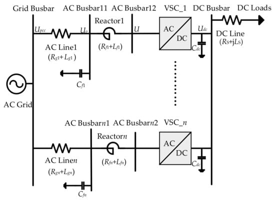
Figure 1.
Topology diagram of the DC distribution system with parallel converters.
The converter is controlled by droop control, and the control block diagram is shown in Figure 2.
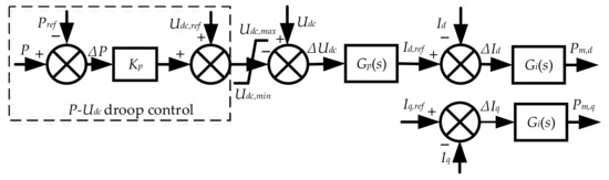
Figure 2.
Converter control block diagram.
The voltage and current dynamic characteristics of the converter in dq rotating coordinate system using the Pike transformation method are expressed by Equations (1)–(4).
where ω is the magnitude of the angular velocity of the output AC voltage of the converter, and the components of the AC-side voltage U of the converter on the dq axis are denoted by Ud and Uq; its value is maintained by the outer-loop voltage control, and the components of the AC-side current I of the converter on the dq axis are denoted by Id and Iq; Uo,d, Uo,q, Io,d, and Io,q are the components of the left AC bus voltage Uo of the reactor in Figure 1 and components of the current Io flowing through the AC line on the dq axis; the reactor in each phase of the line consists of resistance and inductance, denoted by Rf and Lf; Cf is the grounding capacitor connected in parallel with the reactor; the reactor and the grounding capacitor together form a filter. The Laplace operator is denoted by S, and the angular frequency is ω.
The expressions for active power P and reactive power Q at the dq coordinate of the converter output to the AC side of the grid are as follows.
Under the premise of ignoring the active power loss of the converter, the active power absorbed from the DC system is considered to be exactly the same as the active power output to the AC system, and the following equation is obtained.
where the bus voltage on the DC side of the converter is denoted by Udc, and the DC-side current of the converter is Idc.
The joint Equations (5) and (7) achieve linearization of small perturbation, and Equation (8) can be obtained.
In this paper, the P-Udc droop control operates in the unit power factor mode, i.e., it is considered that Iq(0) ≈ 0. The reference value of the system voltage is expressed in terms of the voltage of the AC bus connected to the converter, i.e., in the case of stable operation, the q-axis component of the AC bus voltage (Uo,q(0) ≈ 0) is also zero. Therefore, Equation (8) is simplified as shown in Equation (9).
where Δ indicates the deviation of the operating value from the stable operating value at a certain time; the subscript “(0)” indicates the stable operating value.
The dynamic characteristics of the voltage and current between the AC bus on the left side of the reactor and the AC grid bus are shown in Equations (10) and (11).
Upcc,d and Upcc,q are the components of the AC grid bus voltage Upcc on the d-axis and q-axis, and Rg and Lg are the resistance and inductance of the AC line directly connected to the grid bus.
When small perturbations are performed on Equations (3) and (10), reconnecting them, where ΔUpcc,d = 0, Equation (12) can be obtained.
Through the linearization of Equation (1) and substituting Equation (12), Equation (13) can be obtained.
Equations (12) and (13) are substituted into the corresponding position in Equation (9), and Equation (14) can be obtained.
The expressions of the voltage outer-loop control and the current inner-loop control of the converter P-Udc droop control are shown in Equations (15)–(19).
The reference values Id,ref and Iq,ref are the current signals of the voltage outer-loop controller in the d and q axes. The current I reference value is obtained from the PI control of the AC-side bus voltage using the Gp(s) function in the AC voltage outer-loop controller in the dq coordinate axis, which is called the current inner-loop control Gi(s) current reference signal. Pm,d is the d-axis modulation and demodulation signal of the converter. The inner- and outer-loop controller proportional coefficients are expressed by Kip and Kpp, respectively, while the inner- and outer-loop controller integral coefficients are Kii and Kpi, respectively.
In this paper, the π-type concentrated parameter equivalent circuit can better simulate the real DC line, therefore this alternative model is shown in Figure 3.
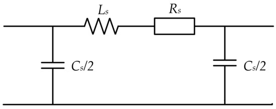
Figure 3.
π-type concentrated parameter equivalent circuit model.
The above figure shows Rs and Ls as the line resistance and reactance, respectively, and distribution capacitance Cs where the stability of the impact is small, and not directly omitted.
3. Virtual Inertia Control
3.1. Time Constant of Inertia
In the conventional AC distribution system, the inertia of the large grid can effectively prevent the system frequency from over-range fluctuations or sudden changes, which provides ample time for the generator to adjust the active output and reconstruct the system balance. The conventional expression for the inertia time constant of the synchronous motor under the AC distribution system is as follows (20).
The energy stored when the rotor speed of the synchronous generator is rated, is denoted by Wk, and the rated capacity of the generator is SN.
Based on the introduction of inertia constants for the AC distribution systems, the inertia time constants for the DC distribution systems can be extrapolated, with the difference that the inertia of the DC system provides damping support for DC voltage fluctuations, rather than frequency. Extending this to a multicommutator DC distribution network with parallel grounded capacitance on the DC side of each commutator, the inertia time constants are shown as (21).
The i-th converter DC-side capacitor value is represented by Cdc,i; the stored energy is Wci; the capacitor capacity is rated at SN,ci; Udc is the converter DC-side voltage value; and n indicates the total number of shunt capacitors on the converter DC side of the system. Hdc is a physical parameter indicating time, which refers to the time required to consume the stored energy when the capacitor voltage is rated. It is evident that as the capacity of the capacitor increases, the stored energy also increases. Furthermore, the more time it takes to consume the energy, the larger the corresponding inertia time constant is. The amount of energy stored in the capacitor is expressed by the concept of inertia. In the actual DC distribution network, there is the disadvantage of a small capacitance value on the DC side, so the virtual inertia control method is proposed to increase the value of inertia time constant on the DC side.
The normal DC system regulates the dynamic voltage slowly, and the system is disturbed by the active power imbalance generally through the DC-side shunt capacitor to absorb or issue power to regulate the whole system to regain the balanced state. The voltage and current relationship of the DC side of the converter with respect to the capacitor is shown in Figure 4.
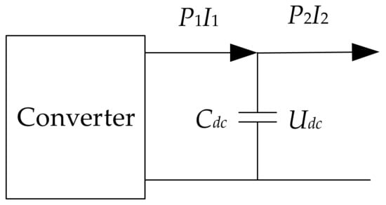
Figure 4.
Voltage–current relationship at the DC side of the converter.
According to the above diagram, the KCL expression of DC capacitance can be obtained as
I2 represents the current value flowing from the DC capacitor to the DC bus, and I1 represents the DC current output at the outlet of the DC side of the converter, which flows in the direction of the DC capacitor. The expression obtained by multiplying the left and right sides of the above Equation (22) by Udc at the same time is transformed into the value of the energy issued or absorbed by the DC capacitor to regulate the system power, as shown in the following Equation (23).
P2 represents the active power flowing from the DC capacitor to the DC bus, and P1 represents the active power output at the outlet of the DC side of the converter, which flows in the direction of the DC capacitor. When the system is not disturbed for normal operation, dUdc/dt = 0 and P2 = P1. When disturbed, the transmitted P2 will be affected to oscillate around the rated value, further leading to poor voltage quality on the user side, which is not conducive to efficient operation of the distribution network. Common control can only suppress voltage oscillation through DC-side capacitance, and the larger the capacitance value, the better the suppression effect, and the result of voltage derivative dUdc/dt is closer to zero. However, the common DC-side capacitance cannot be increased infinitely, and the value is generally small.
The large power grid has a large mechanical inertia. Therefore, changing the traditional converter control mode to make full use of the inherent inertia of the large power grid through additional control, with the purpose of releasing the energy stored in the generator rotor and ensuring the dynamic stability of the DC voltage, was considered. Therefore, this additional control is called virtual inertia control. Compared with the original droop control, this control expands the capacity of the parallel capacitor on the DC side of the converter in the form of a virtual capacitor Cvir, which can enhance system inertia and damping and improve the dynamic stability of the DC bus voltage after being disturbed. The magnitude of the inertia is strictly positively related to the capacitor Cvir.
The virtual inertia control can quickly adjust the active power P1 of the DC side of the converter in case of voltage deviation, so that the converter can absorb or emit active power ΔP1, when the DC voltage changes dynamically. The expression of the original P1 is as follows.
P1′ denotes the active power output at the outlet of the DC side of the converter after the additional virtual inertia control. Through substituting Equation (24) into Equation (23), Equation (25) can be obtained.
The left side of the above equation indicates that under virtual inertia control when the converter output power is not consistent with the active power required by the load, in addition to the original ordinary capacitor Cdc, the virtual capacitor also achieves system power balance by charging and discharging power. When the system is operating in an unbalanced mode, the virtual capacitor will additionally generate active power required by the load, which slows down the regulation pressure of the original droop control with a small DC capacitor and increases the inertia of the system. When the voltage variation does not exceed the allowable range, ΔP1 does not work. In the case of P1 = P1′, it means the virtual capacitor Cvir is zero.
Under virtual inertia control, the expression for the energy stored in all capacitors on the DC side is shown in Equation (26).
Ci is all the capacitors on the DC side, including the normal capacitor Cdc,i and the virtual capacitor Cvir,i. The increase of Ci is mainly achieved by increasing the virtual capacitor Cvir.
The calculation of the inertia time constant of the AC system is extended to the DC system. It is known that the inherent inertia time constant of the DC system is the time taken from the energy stored in the DC-side capacitor at the rated voltage to its complete consumption, and the inertia time constant of the system after adding the virtual inertia control is as shown in Equation (27).
The total number of DC-side capacitors in the above equation is n, where the first m converters are attached with inertia control, which generates m virtual capacitors on their DC side, and the i-th of the m virtual capacitors is denoted by Cvir,i. The capacity rating of the capacitor and the voltage value on the DC side of the converter are still denoted by SN,ci and Udc. In the actual DC distribution system, the number of converters participating in the virtual inertia control should be decided by considering the efficiency of converter utilization, investment cost, voltage overshoot range, voltage quality requirements, etc., often in a coordinated control manner. After the fluctuation of system power or bus voltage, the size of the virtual capacitor is automatically adjusted according to the deviation size and voltage change rate, which can further improve the system response speed. The presence of the virtual capacitor reduces the capacity requirement of the original capacitor on that side, which fundamentally reduces the operating pressure of the system. It was found that the larger the virtual capacitor is, the less obvious the voltage overshoot phenomenon is, and the voltage changes more slowly, reducing the impact on electrical equipment and load, etc. The disadvantage is that the time required to restore the voltage to the steady-state value is prolonged. When the virtual capacitor becomes smaller, the voltage regulation time is reduced, but the rapid change of voltage will reduce the life of electrical equipment. Therefore, when a higher quality system voltage is required, this can be achieved by increasing Cvir,i.
3.2. Virtual Inertia Control Based on First-Order Filters
The mechanical inertia of DC distribution systems is released by additional inertia control for maintaining the voltage smoothly. The virtual inertia control makes the rotor emit or absorb kinetic energy by adjusting the generator speed. The rotor decelerates and releases the kinetic energy after the system is disturbed by the voltage reduction, and the rotor will reabsorb the kinetic energy and resume the speed after the system is restored to stability. Unlike previous studies, this section adds a first-order filtering link before the virtual inertia control, and the input signal’s ability to resist high-frequency signal disturbance is greatly enhanced, reducing the voltage reduction amplitude and improving the disadvantage that the input signal of the differential link is easily swamped by high-frequency disturbances. The voltage and current signals in the additional inertia control are taken from the d-axis component of the AC side of the converter, so the data acquisition is faster and more accurate without error. The control link no longer contains the rotor rotational inertia and electric angular velocity, generator pole logarithm and other parameter values. Therefore, the control process is more concise, and can be more easily applied to the actual DC power distribution systems.
With the additional virtual inertia control of the converter, the inertia power expression provided by the grid side is shown as Equation (28).
where Cvir is the new equivalent virtual capacitance on the DC side of the converter after the additional virtual inertia control.
When the DC side of the system oscillates due to changes in load or parameters, the charging and discharging capacity of the original grounded capacitor on the DC side of the converter will also fluctuate, and its charging and discharging power expression is shown in (29).
The above equation Cdc represents the original shunt capacitance on the DC side of the converter in F, and udc is the system DC bus voltage in V.
In particular, the forward Euler approximation method is used, the sampling period is set to T, the DC bus voltage udc(0) is taken at the previous moment when the interval from udc is small, and the first-order differential expression of the capacitor charging and discharging power becomes the form of difference ratio, which is equivalent to transforming the curve function problem into a linear slope solution and facilitates the model building. The second-order accuracy of the forward Euler method can also be guaranteed as long as the step size chosen is small enough. The above Equations (28) and (29) are rewritten as Equations (30) and (31), respectively.
In the derivation of the converter small disturbance conductance, it is known that the expression of the converter output active power change when the system is disturbed is as follows (32).
ΔP is compensated by the active power generated by the original ground capacitor and the virtual capacitor, so
In the actual distribution network, the energy stored in the DC capacitance Cdc is much lower than the rotor kinetic energy, so the generator speed is less affected when the voltage fluctuates, and the synchronous generator cannot provide inertia support continuously and efficiently. The traditional method of increasing generator inertia during DC voltage oscillations is to increase the difference between generator speed and rated speed. In order to prevent the system from voltage oscillations under the dual influence of parameter changes as well as through external disturbances and to improve the system immunity, the damping component Dr(udc − Udc,N) is introduced in the right-hand side of Equation (33) above to obtain
The voltage damping factor is expressed as Dr. The DC-side bus voltage rating is effectively Udc,N.
Among them
Based on the derivation of the equation for the dynamic small disturbance conductance of the converter, the expression for Kr is obtained as shown in (36) below.
The value range of Dr is determined according to Equation (37)
ΔUdc,max is the difference between the maximum and minimum DC bus voltage, and IN is the rated DC-side current of the converter.
Substituting Equation (37) into Equation (36), the additional inertia control generates current compensation to correct the output current reference value Id,ref.
The voltage damping part of the above equation is represented by Mr.
The control block diagram of voltage damping Mr is shown in Figure 5.
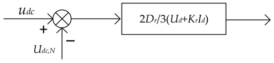
Figure 5.
Voltage damping Mr control block diagram.
When the load increases beyond the rated value, it will lead to a reduction in the system frequency, which in turn will cause the DC bus voltage to drop. In this case, the voltage is compensated by releasing the energy stored in the DC-side capacitor. In the actual distribution network, there may be a situation where the load is continuously put in, which will directly cause the DC voltage to stay below its rated value. In view of the small inertia and damping of the P-Udc droop control, which cannot hinder the voltage transient oscillation to restore the DC voltage to its rated value, this section adds the virtual inertia control based on a synchronous generator to the converter P-Udc droop control after the voltage outer-loop control, and the complete control framework is shown in Figure 6b below. Figure 6a shows the traditional control block diagram of the converter.
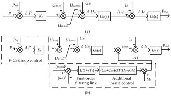
Figure 6.
(a) Conventional control block diagram for converters. (b) Additional inertia control block diagram of voltage outer loop of converter.
4. Simulation Analysis and Discussion
4.1. Simulation Analysis
Simulation was performed using DIgSILENT software. The software contains almost all commonly used functions for power system analysis, such as tide calculation, short circuit calculation, electromechanical transient and electromagnetic transient calculation, harmonic analysis, small disturbance stability analysis, etc. The software is suitable for the study of droop control stability in this paper. Simulation was achieved using a modified IEEE 33-node power distribution system arithmetic example.
If we let n = 2 in Figure 1, the simulation model of two converter parallel DC distribution system is derived based on dynamic small disturbance conductance theory, including three parts of dynamic conductance model of converter, DC line and DC load. The system parameters are shown in Table 1.

Table 1.
System parameters of DC distribution network with two parallel converters.
The system was first verified with and without the voltage dynamic characteristics of the virtual inertia control, and the parameters C and D were specifically defined during the additional inertia control build.
In the following, keeping the rest of the conditions unchanged, a virtual inertia control based on a first-order filter was added to the original control only, and the additional control was added to the voltage outer loop to compensate for the d-axis current reference. A small perturbation was then given to the distribution system to allow the following comparison of the voltage waveforms with and without the virtual control.
When C = D = 0.75, the comparison of DC bus voltage waveforms with and without virtual inertia control is shown in Figure 7 below. According to the simulation results, the virtual inertia control effectively solved the interaction instability problem among multiple converters, which provided technical support and safety guarantees for the stable operation of the multiple converter parallel system.
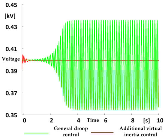
Figure 7.
Voltage waveform with or without virtual inertia control.
The load in the actual DC distribution system is dynamically changing in real time, and in most cases its fluctuation range will exceed the allowed critical value. Therefore, in order to better reflect the actual system situation, the DC bus voltage simulation waveform is shown in the green waveform of Figure 8 when the DC load of the system was suddenly increased by 40% at 1 s, it can be seen that its stability became significantly worse and the voltage oscillation was more violent compared with the system without the applied load disturbance.
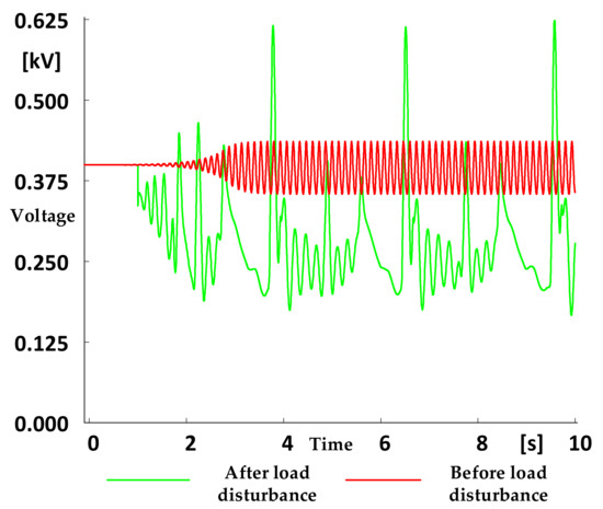
Figure 8.
Voltage waveform with or without load disturbance.
For the above scenario with load disturbance, virtual inertia control was added to compare the voltage waveforms with and without the virtual inertia control. It was found that even with the load disturbance, the additional inertia control could still effectively compensate for the voltage and restore the voltage to its steady-state value without falling too far below the original rated value, resulting in a reduction in system operating efficiency, as shown in Figure 9.
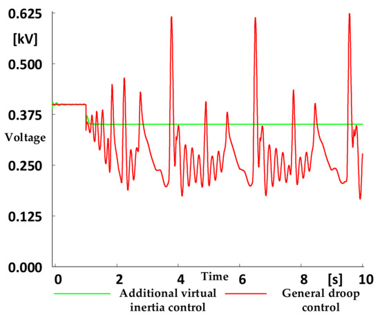
Figure 9.
Voltage waveform with or without virtual inertia control under load disturbance.
Next, the DC load was snapped by 40% at 2 s. The voltage waveform without virtual inertia control is shown in Figure 10a, and the waveform with additional virtual inertia control is shown in Figure 10b. Adding the perturbation of load plunge made the system stability become obviously poor, and the system voltage fluctuation was very violent. However, after adding the additional inertia control, the system voltage could be effectively compensated and the final voltage was restored to the steady-state value.
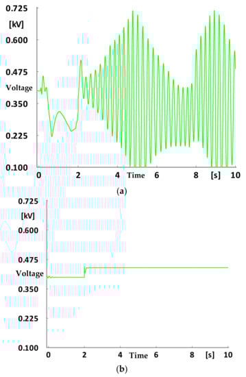
Figure 10.
(a) Voltage waveform without virtual inertia control after a sudden load shedding disturbance. (b) Voltage waveform with virtual inertia control after a sudden load shedding disturbance.
Finally, the stability impact of virtual inertia control-related parameter changes was analyzed, and the following time-domain simulation was carried out to verify the parallel system of two converters with load perturbation. When the parameter C was taken as 0.95, 0.75, and 0.55, the stability declined. The voltage waveform comparison is shown in Figure 11.
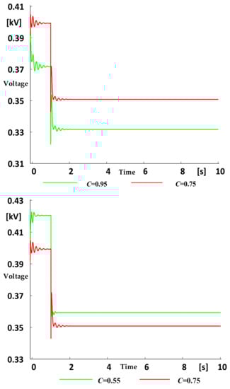
Figure 11.
DC bus voltage waveform with different C.
The simulated waveforms of DC voltage at D of 0.95, 0.75, and 0.55 are shown in Figure 12 below. It can be seen that as the D, i.e., Dr, increased, the voltage dip increased slightly, and the stability became worse.
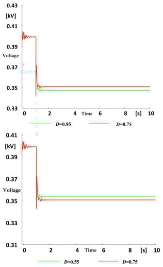
Figure 12.
DC bus voltage waveform with different D.
4.2. Experimental Verification
A hardware-in-the-loop experimental platform based on an RT Box was built in Figure 13, which consisted of control board, an RT Box, an oscilloscope and a PC. The control board adopted a TMS320F28069 chip from Texas Instruments.
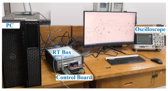
Figure 13.
Hardware-in-the-loop experimental platform.
A hardware-in-the-loop system of a double-terminal DC distribution system with an RT Box was built for further verification, as shown in Figure 14.
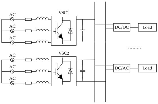
Figure 14.
Simplified model of a DC distribution system.
The simulation model was built within PLECS software based on the simplified model shown in Figure 14. The rated power of the two converters was set to 0.025 MVA, and the rated voltage of the three-phase balanced bus connected to the AC side of each converter was 0.2 kV. The specific control parameters are referred to in Table 1. The voltage on the DC side was 0.4 kV, the total DC load power was set to 20 kW, and the frequency was 50 Hz. Keeping the rest of the conditions unchanged, a small disturbance of load increase by 20% was applied to the system at 3 s under the two control modes.
The DC bus voltage waveform is shown in Figure 15, where the red voltage waveform represents the system without virtual inertia control and the green voltage waveform represents the system with virtual inertia control. Although the DC bus voltage dropped in both cases after the load surge, the dynamics of the system with virtual inertia control became significantly better than that of the system without virtual inertia control, and the voltage drops were reduced and the stability became better.
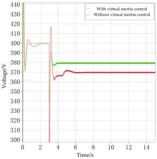
Figure 15.
DC-side bus voltage waveform.
The following is a physical simulation experiment using the RT Box experiment bench.
Y1 represents the difference between udc and Udc.N without load perturbation, and Y2 represents the difference between udc and Udc.N after load perturbation. The value of Y2 in Figure 16 is larger than that of Y2 in Figure 17. It is obvious that for the system with virtual inertia control, the difference after increasing the load disturbance significantly decreased, and the bus voltage drop on the DC side was smaller, so the stability became better. This demonstrates that the system with virtual inertia control was more resilient in the face of load perturbation which would make the system more stable.
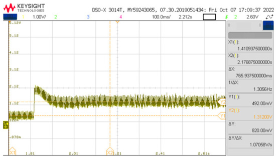
Figure 16.
Voltage differential without virtual inertia control.
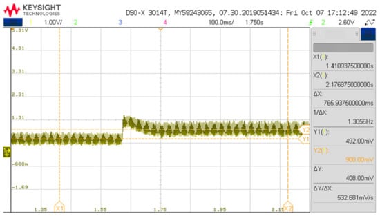
Figure 17.
Voltage differential with virtual inertia control.
5. Conclusions
The improved virtual inertia control based on the first-order filtering link attached to the converter P-Udc control can effectively improve the stability of the system, which is conducive to the safe and high-quality operation of the DC distribution systems with multiple converters in parallel. It overcomes the inherent shortcomings of droop control while retaining the advantages of the multiple converter operation mode. When the damping coefficient Dr or virtual capacitance Cvir increased, the DC bus voltage drop of the load disturbed system was larger, and the time required to recover to the new steady-state value was longer, so the system stability became worse. However, it is worth noting that the change in voltage dip was significantly reduced when the damping factor Dr was varied, indicating that voltage damping can improve the ability of bus voltage to cope with sudden changes in load and ensure voltage quality.
Author Contributions
Q.G. conceived the main idea and wrote the manuscript with guidance from K.P.; Y.J. was responsible for the physical experiments and writing—review and editing; K.P. was responsible for the methodology, project administration, and funding acquisition; L.L. was responsible for obtaining the experimental data. All authors have read and agreed to the published version of the manuscript.
Funding
The study in this paper was supported by the National Natural Science Foundation of China (51807112).
Acknowledgments
The authors would like to thank the anonymous reviewers for their careful reading and many helpful suggestions to improve the presentation of this paper.
Conflicts of Interest
The authors declare no conflict of interest.
Nomenclature
| Abbreviations | |
| DC | direct current |
| AC | alternating current |
| HFO | High-frequency oscillations |
| PLL | phase-locked loop |
| VSG | virtual synchronous generator |
| ROCOF | rate of change of frequency |
| MPC | adaptive virtual inertia system |
| MG | islanded microgrid |
| OSVI | optimized second-order virtual inertia |
| RESs | renewable energy sources |
| VSC-HVDC | line-commutated converter based on a voltage source converter |
| MMC | modular multilevel converter |
| Greek symbols | |
| ω | angular velocity |
| English symbols | |
| P | active power |
| Q | reactive power |
| U | voltage |
| I | current |
| R | resistor |
| L | inductor |
| C | capacitor |
| H | inertia time constant |
| W | energy |
| S | capacity |
| Y | voltage difference |
| d | d-axis |
| q | q-axis |
| T | time period |
| n | number of capacitors |
| N | rated value |
| Dr | voltage damping factor |
| Mr | voltage damping |
| ref | reference value |
| vir | virtualization |
References
- Zou, W.; Dong, H.; Chen, X.; Liu, K. Small Signal Modeling and Decoupling Control of VSC-MTDC. In Proceedings of the 2020 Chinese Control and Decision Conference (CCDC), Hefei, China, 22–24 August 2020; pp. 2786–2792. [Google Scholar] [CrossRef]
- Li, X.; Peng, K.; Zhang, X.; Gong, Q.; Liu, Y.; Jiang, S. Robust stability control for high frequency oscillations in flexible DC distribution systems. Int. J. Electr. Power Energy Syst. 2022, 137, 107833. [Google Scholar] [CrossRef]
- Yao, G.; Peng, K.; Li, X.; Jiang, S.; Liu, Y. A reduced-order model for high-frequency oscillation mechanism analysis of droop control based flexible DC distribution system. Int. J. Electr. Power Energy Syst. 2021, 130, 106927. [Google Scholar] [CrossRef]
- Ji, Y.; Yuan, Z.; Zhao, J.; Zhao, Y.; Li, G.; Li, Y. Control scheme for multi-terminal VSC-basedmedium-voltage DC distribution networks. Inst. Eng. Technol. 2019, 16, 2935–2940. [Google Scholar]
- Kerdphol, T.; Rahman, F.S.; Watanabe, M.; Mitani, Y. Robust Virtual Inertia Control of a Low Inertia Microgrid Considering Frequency Measurement Effects. IEEE Access 2019, 7, 57550–57560. [Google Scholar] [CrossRef]
- Sun, D.; Liu, H.; Gao, S.; Wu, L.; Song, P.; Wang, X. Comparison of Different Virtual Inertia Control Methods for Inverter-based Generators. J. Mod. Power Syst. Clean Energy 2020, 8, 768–777. [Google Scholar] [CrossRef]
- Wang, X.; Yang, T. Study on dynamic characteristic optimization of virtual inertia control for the grid-connected converters in DC micro grid. J. Phys. Conf. Ser. 2021, 1885, 042066. [Google Scholar] [CrossRef]
- Liao, H.; Zeng, G.; Huang, B.; Ma, C.; Chen, G.; Zhao, J. Optimal Control Virtual Inertia of Optical Storage Microgrid Based on Improved Sailfish Algorithm. Wuhan Univ. J. Nat. Sci. 2022, 27, 218–230. [Google Scholar] [CrossRef]
- Shi, K.; Ye, H.; Song, W.; Zhou, G. Virtual Inertia Control Strategy in Microgrid Based on Virtual Synchronous Generator Technology. IEEE Access 2018, 6, 27949–27957. [Google Scholar] [CrossRef]
- Fawzy, A.; Bakeer, A.; Magdy, G.; Atawi, I.E.; Roshdy, M. Adaptive Virtual Inertia-Damping System Based on Model Predictive Control for Low-Inertia Microgrids. IEEE Access 2021, 9, 109718–109731. [Google Scholar] [CrossRef]
- Xu, H.; Yu, C.; Mao, F.; Liu, C.; Wang, Q.; Zhang, X. A Power Oscillation Damping Algorithm of Distributed Generators Based on Optimized Second-order Virtual Inertia. In Proceedings of the IEEE 12th Energy Conversion Congress & Exposition—Asia (ECCE-Asia), Singapore, 24–27 May 2021; pp. 2369–2374. [Google Scholar] [CrossRef]
- Kerdphol, T.; Watanabe, M.; Hongesombut, K.; Mitani, Y. Self-Adaptive Virtual Inertia Control-Based Fuzzy Logic to Improve Frequency Stability of Microgrid With High Renewable Penetration. IEEE Access 2019, 7, 76071–76083. [Google Scholar] [CrossRef]
- Ren, M.; Li, T.; Shi, K.; Xu, P.; Sun, Y. Coordinated Control Strategy of Virtual Synchronous Generator Based on Adaptive Moment of Inertia and Virtual Impedance. IEEE J. Emerg. Sel. Top. Circuits Syst. 2021, 11, 99–110. [Google Scholar] [CrossRef]
- Zhou, T.; Chen, Z.; Ren, B.; Bu, S.; Wang, P. Damping Torque Analysis of VSC-HVDC Supplementary Damping Controller for Small-Signal Stability. IEEE Access 2020, 8, 202696–202706. [Google Scholar] [CrossRef]
- Gu, M.; Meegahapola, L.; Wong, K.L. Damping Performance Analysis and Control of Hybrid AC/Multi-Terminal DC Power Grids. IEEE Access 2019, 7, 118712–118726. [Google Scholar] [CrossRef]
- Tirtashi, M.R.S.; Samuelsson, O.; Svensson, J. Impedance Matching for VSC–HVDC and Energy Storage Damping Controllers. IEEE Trans. Power Deliv. 2017, 33, 1016–1017. [Google Scholar] [CrossRef]
- Tinajero, M.Z.; Ornelas-Tellez, F.; Garcia-Barriga, N. Optimal Control of an Inverter-based Virtual Synchronous Generator with Inertial Response. IEEE Lat. Am. Trans. 2022, 20, 780–786. [Google Scholar] [CrossRef]
- Iqbal, M.T.; Maswood, A.I.; Tariq, M.; Iqbal, A.; Verma, V.; Urooj, S. A Detailed Full-Order Discrete-Time Modeling and Stability Prediction of the Single-Phase Dual Active Bridge DC-DC Converter. IEEE Access 2022, 10, 31868–31884. [Google Scholar] [CrossRef]
- Iqbal, M.T.; Maswood, A.I. A switchable bilinear discrete-time modeling for the stability analysis of the digitally controlled three-phase dual active bridge dc-dc converter. In Proceedings of the IECON 2020: The 46th Annual Conference of the IEEE Industrial Electronics Society, Singapore, 18–21 October 2020; pp. 3291–3296. [Google Scholar] [CrossRef]
- Carbone, L.; Cosso, S.; Kumar, K.; Marchesoni, M.; Passalacqua, M.; Vaccaro, L. Stability Analysis of Open-Loop V/Hz Controlled Asynchronous Machines and Two Novel Mitigation Strategies for Oscillations Suppression. Energies 2022, 15, 1404. [Google Scholar] [CrossRef]
- Li, J.; Chen, J.; Xue, Y.; Qiu, R.; Liu, Z. Stability Analysis Method of Parallel Inverter. Math. Probl. Eng. 2017, 2017, 6062798. [Google Scholar] [CrossRef]
- Iqbal, M.T.; Maswood, A.I.; Tafti, H.D.; Tariq, M.; Bingchen, Z. Explicit discrete modelling of bidirectional dual active bridge dc–dc converter using multi-time scale mixed system model. IET Power Electron. 2020, 13, 4252–4260. [Google Scholar] [CrossRef]
- Iqbal, M.T.; Maswood, A.I. A frequency domain based large and small signal modeling of three phase dual active bridge. In Proceedings of the IECON 2020: The 46th Annual Conference of the IEEE Industrial Electronics Society, Singapore, 18–21 October 2020; pp. 3421–3426. [Google Scholar] [CrossRef]
- Sanders, S.; Noworolski, J.; Liu, X.; Verghese, G. Generalized averaging method for power conversion circuits. IEEE Trans. Power Electron. 1991, 6, 251–259. [Google Scholar] [CrossRef]
- Lammert, G.; Yamashita, K.; Ospina, L.D.P.; Renner, H.; Villanueva, S.M.; Pourbeik, P.; Ciausiu, F.E.; Braun, M. Modelling and Dynamic performance of inverter based generation in power system transmission and Distribution studie. Water Energy Int. 2017, 2017, 1899–1902. [Google Scholar] [CrossRef][Green Version]
- Meng, Y.; Yu, J.; Shang, S.; Liu, B.; Gao, X. Modeling and Control of Modular Multilevel AC/AC Converter in Y Configuration for Fractional Frequency Transmission System. IEEJ Trans. Electr. Electron. Eng. 2020, 15, 741–750. [Google Scholar] [CrossRef]
- Gruson, F.; Tlemcani, A.; Li, Y.; Delarue, P.; Le Moigne, P.; Guillaud, X. Model and control of the DC–DC modular multilevel converter with DC fault tolerance. EPE J. 2020, 30, 153–164. [Google Scholar] [CrossRef]


Publisher’s Note: MDPI stays neutral with regard to jurisdictional claims in published maps and institutional affiliations. |
© 2022 by the authors. Licensee MDPI, Basel, Switzerland. This article is an open access article distributed under the terms and conditions of the Creative Commons Attribution (CC BY) license (https://creativecommons.org/licenses/by/4.0/).