Abstract
The tension legs are the essential parts of the tension legs platform-type (TLP-type) floating offshore wind turbine (FOWT) against the extra buoyancy of FOWT. Therefore, the TLP-type FOWT will face the risk of tension leg failure. However, there are seldom analyses on the hydrodynamic response and tension leg failure performance of FOWT with inclined tension legs. In this paper, a hydrodynamic model was established using three-dimensional hydrodynamic theory and applied in the motion response and tension analyses of FOWT with conventional and new tension leg arrangements on Moses. The influence of draft and tension leg arrangement on the performance of FOWT with inclined tension legs were studied. The optimum draft was the height of the column and lower tensions were obtained for the new tension leg arrangement. Moreover, the tension leg failure performance of FOWT with inclined tension legs was evaluated under different failure conditions. The results illustrated that the FOWT with the new tension leg arrangement can still operate safely after one tension leg fails.
1. Introduction
With the rapid economic development and growth, the demand for energy is increasing. Due to the depletion of fossil fuel, renewable energy is gaining more and more attention. Wind energy is an alternative because of its environmentally friendly, and it has developed rapidly in recent years [1]. The wind energy is also one of the most efficient renewable energies due to its low operation cost and the availability of a large amount of wind power [2]. Due to visual pollution from shore, routes of coastal ships, etc., the offshore wind farms will inevitably expand from shallow water to deep water. In deep seawater, the construction and installation costs of the fixed foundation for the wind turbine, commonly used in shallow seawater, will sharply increase. Therefore, the floating foundation is an alternative to apply in deep seawater.
The floating foundations mainly include the spar, tension legs platform (TLP), barge, and semi-submersible types. Among them, the TLP-type floating offshore wind turbine is generally composed of an upper wind turbine tower, central column, side column [3,4], side pontoons [5,6] or side spokes [7], supporting components, and a mooring system. The upper wind turbine tower can be assembled on land or in a shipyard to avoid the risk of offshore assembling and installed on the supporting components and central column. Then, the mooring system will be connected to the supporting components and central column. Due to the high stiffness of mooring cables, the natural frequency of TLP-type FOWT is much higher than the wave frequency. Therefore, the TLP-type FOWT should have good hydrodynamic performance [8]. Due to the large buoyancy from the central column, the extra buoyancy needs to be balanced using mooring cables as tension legs [9]. Thus, the mooring system becomes particularly essential for TLP-type FOWT. The failure of certain tension legs may lead to the overturning and sinking of the TLP-type FOWT.
TLP-type structures have been extensively studied and used over the past 40 years as support facility platforms for oil and gas extraction from deep and ultra-deep subsea reservoirs. After serious damages to the floating multi-well units and production platforms in the Gulf of Mexico by hurricanes Katrina and Rita [3], a serious failure with tendons occurred with the A-Typhoon TLP in the Gulf of Mexico during the passage of hurricane Rita [10]. This failure resulted in the capsizing of the platform and led to lessons learned regarding the connection of tendon connectors with subsea support. Many researchers have conducted many numerical simulations and experimental studies for the motion response and the mooring system failure of TLP. Yang and Kim [11] developed a time-domain, nonlinear, global-motion analysis program for floating hulls coupled with risers/mooring line and investigated the transient effects of tendon disconnection on the global performance of TLP during harsh environmental conditions. Jameel et al. [12] and Oyejobi et al. [13,14] studied the hydrodynamic responses of TLP with intact tendons or one tendon missing under moderate and extreme sea conditions. Tabeshpour et al. [15] investigated the effect of damaged tendons on the performance and tension of TLP in the wave frequency range. Yu et al. [16] studied the coupled hydrodynamic response of TLP after the failure of one or multiple tendons under extreme sea conditions. Wu et al. [17] studied the transient effect of one tendon failure on the motion response of Windstar TLP using the FAST software. Cheng et al. [18] analyzed the complex motion of TLP after the mooring system was partially damaged. In conclusion, it is recommended to conduct hydrodynamic analysis of the TLP platform under the combined action of wave, current, and wind loads. These researchers showed that the malfunction of any tendon would cause an increase in the motion response and a surge of the tension response. A study on the tendon failure performance of TLP under complex loads was conducted [19]. Some suggestions were put forward to reduce the risk of tendon failure. Chung et al. [20] proposed a new algorithm for real-time monitoring of the tension and bending moment of tendons. Real-time structural health monitoring can prevent tension legs’ failure.
Many scholars studied the hydrodynamic performance and mooring system failure of FOWT in complex marine environments [21,22,23,24]. Bae et al. [25] conducted numerical simulation of semi-submersible FOWT with a broken mooring line using CHARM3D and FAST. Li et al. [26] developed a coupled aero-hydro-elastic numerical model to study the transient response and mooring line failure of Spar FOWT. It was found that the drift of semi-submersible FOWT with a broken mooring line was very obvious. This may lead to continuous failure of wind turbines. Le et al. [27] studied the hydrodynamic response of full-submersible FOWT under the action of turbulence and irregular waves using FAST. The results showed that full-submersible FOWT with one mooring line failure maintains good performance. Yang et al. [28] analyzed and predicted the transient behavior and mooring failure of barge FOWT under normal and extreme sea conditions using FAST and AQWA(F2A). Ahmed et al. [29] investigated the hydrodynamic response of Spar FOWT when one or more mooring lines were damaged. Yang et al. [30] analyzed and predicted the hydrodynamic response of a floating offshore wind turbine under different tendon failure scenarios. Sakaris et al. [31] and Sakaris et al. [32] investigated the structural health monitoring on the tendons of FOWT and the tendon damage diagnosis of FOWT, and the results showed that the damage detection can identify the tendon damage.
Wang et al. [33] used AWQA to analyze the “aero-hydro” coupling hydrodynamic response of the TLP-type FOWT. More attention should be paid to the pitch and surge motion of TLP-type FOWT. However, there are seldom studies on the hydrodynamic response and the tension leg failure performance of FOWT with inclined tension legs [34,35]. Therefore, based on the three-dimensional potential flow theory, a hydrodynamic model in deep seawater was established and applied in the hydrodynamic analyses of FOWT with inclined tension legs. The effects of draft and tension leg arrangement on the hydrodynamic and tension responses of FOWT with inclined tension legs are studied. The tension legs’ failure performance analyses of FOWT with different tension leg arrangements are also analyzed.
2. Hydrodynamic Theory of Floating Body
The hydrodynamic response of the floating body in deep seawater was decomposed into two parts, as shown in Figure 1. One was the diffraction response and the other was the radiation response. The diffraction velocity potential was generated by the fixed body under the action of an incident wave. The radiation velocity potential was generated by the forced oscillation under still water. The hydrodynamic response was established in 3D Cartesian coordinates, as shown in Figure 1. In Figure 1a,b, the x-y plane is the hydrostatic surface, and the z-axis is vertically upward. In Figure 1c, the six degrees of freedom of FOWT with inclined tension legs are: surge, sway, heave, roll, pitch, and yaw.
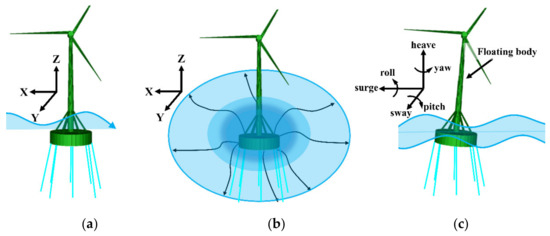
Figure 1.
The hydrodynamic response of floating body in waves. (a) Diffraction response, (b) radiation response, and (c) hydrodynamic response.
2.1. Assumptions
The assumptions are listed as follows:
- (1)
- The fluid is uniform, incompressible, and inviscid.
- (2)
- The water flow is irrotational.
- (3)
- The free surface wave is a linear, small-amplitude wave.
- (4)
- The floating body moves in a small-amplitude and simple harmonic motion.
2.2. Load Calculation
The wind load, , can be defined by Equation (1):
where, is the basic wind pressure, is the height coefficient of the windward structure, is the structure shape coefficient, and is the windward area of the windward component.
The basic wind pressure, , can be expressed as Equation (2):
where, is the air density, and is the average wind speed corresponding to the height, Z, at the average time of T.
The current load, , is calculated by Equation (3):
where, is the current speed, is the projected area of the floating body component in the plane perpendicular to the current direction, is the mass density of seawater, and is the coefficient of the current load.
3. Hydrodynamic Modeling of FOWT with Inclined Tension Legs
3.1. Hydrodynamic Model
The hydrodynamic model of FOWT with inclined tension legs in deep seawater was established under a random wave. The random wave was input using the Joint North Sea Wave Project (JONSWAP) spectrum, which is the most systematic observational data of North Sea waves from 1968 to 1969 obtained by the United Kingdom, the Netherlands, the United States, and the Federal Republic of Germany. The JONSWAP spectrum was proposed with the consideration of wind speed and fetch, as Equation (4) [36]:
where, α is a dimensionless constant, is the peak angular frequency of the wave, which can be calculated using , U (m/s2) is the wind speed, x (km) is the wind range, γ is the peak enhancement factor, and σ is the peak shape parameter. Here, σ = 0.07 when ω ≤ ωp and σ = 0.09 when ω > ωp.
In this model, the FOWT with inclined tension legs was subjected to current, wind, and wave. The random wave component was described by the three-parameter JONSWAP spectrum, that included a significant wave height of 1.5 m, a spectrum peak period of 6.67 s, and a peak enhancement factor (γ) of 2.5. The environmental conditions are as shown in Table 1.

Table 1.
Environmental conditions.
3.2. Numerical Model of FOWT with Inclined Tension Legs
The physical model of FOWT with inclined tension legs is shown in Figure 2. The wind turbine tower was installed on the central column and fixed by six hollow steel tubes. The tension legs were connected to the column and the seabed. The numerical model of FOWT with inclined tension legs (shown in Figure 3) was established through the hydrodynamic simulation software Moses [37]. The parameters and material properties of the FOWT foundation with inclined tension legs are presented in Table 2 and Table 3.
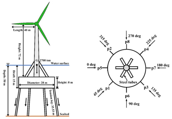
Figure 2.
Physical model of FOWT with inclined tension legs.
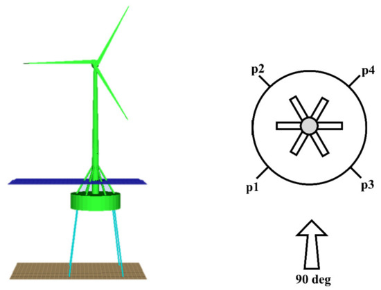
Figure 3.
Numerical model of FOWT with four tension legs.
Table 2.
Main parameters of FOWT with inclined tension legs.
Table 3.
Material properties of FOWT with inclined tension legs.
3.3. RAOs and Motion Responses of FOWT with Inclined Tension Legs
3.3.1. RAOs
By conducting the hydrodynamic analyses of FOWT with inclined tension legs in frequency, the response amplitude operator (RAO) and motion response in each degree of freedom were obtained under the incident wave at 0, 45, 90, 135, and 180 degrees for a FOWT foundation of 15 m (shown in Figure 4).
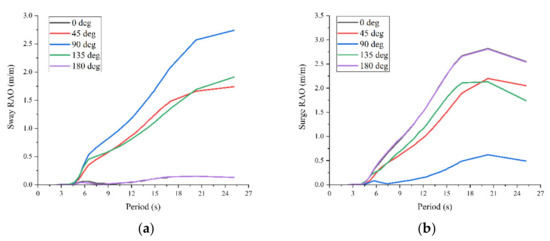
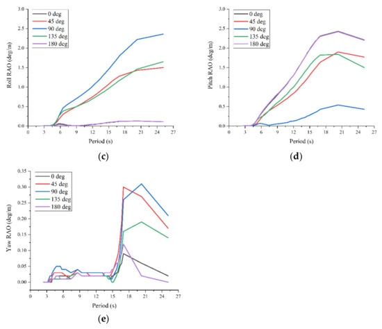
Figure 4.
RAO for each degree of freedom: (a) Sway RAO, (b) Surge RAO, (c) Roll RAO, (d) Pitch RAO, and (e) Yaw RAO.
As in Figure 4a−d, the trendlines of RAOs of four degrees of freedom were basically the same under different angles of incident wave. The RAOs of sway, surge, roll, and pitch were large in 6 to 20 s of the wave period, but the RAO of yaw had the largest response in 15 to 20 s of the wave period. Therefore, it is not recommended to operate in greater than 20 s of the wave period.
3.3.2. Motion Responses
In the time domain, a total of 300 s was simulated, the environmental conditions’ input parameters were the same as in Table 1, and the parameters and material properties were the same as in Table 2 and Table 3. The simulation results of 100−300 s were selected for analysis, as shown in Figure 5a, and the motion response of sway was greater than that of surge. The maximum value of the motion response of surge was 0.27 m, which occurred at 229 s, and the minimum value was −0.3 m, which occurred at 269 s. The maximum value of the motion response of sway was 0.67 m, which occurred at 208 s, and the minimum value was −1.06 m, which occurred at 212 s. As shown in Figure 5b, the motion response of roll was greater than that of pitch and yaw. The maximum value of the motion response of roll occurred at 208 s, which was 0.47 degrees, and the minimum value occurred at 212 s, which was −0.75 degrees. The maximum value of the motion response of pitch occurred at 268 s, which was 0.21 degrees, and the minimum value occurred at 229 s, which was −0.19 degrees. The maximum value of the motion response of yaw occurred at 277 s, which was 0.17 degrees, and the minimum value occurred a total of 5 times, where the first minimum value occurred at 220 s, which was −0.19 degrees. Since the angle of the incident wave is the same as the direction of roll and sway, these phenomena that the motion responses of roll and sway are larger than those of other degrees of freedom are correct.
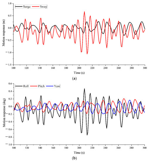
Figure 5.
Motion response of each degree of freedom of 4 tension legs: (a) surge and sway motion response, and (b) roll, pitch, and yaw motion response.
3.4. Parametric Study of FOWT with Inclined Tension Legs
To investigate the effects of draft and tension leg arrangement, a parametric study of FOWT with inclined tension legs was conducted. Four tension legs were used for conventional tension leg arrangement, as shown in Figure 3, while eight tension legs were used for the new tension leg arrangement. One more tension leg was added between the two adjacent tension legs of the conventional tension leg arrangement. The angle between the two tension legs is 45 degrees for the eight tension legs condition. The numerical model for TLP-type FOWT with the new tension leg arrangement is shown in Figure 6.
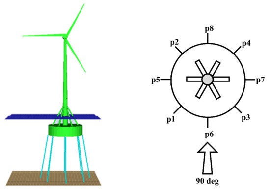
Figure 6.
Numerical model with eight tension legs.
3.4.1. Effect of Draft
In this section, the input parameters were the same as in Section 3.3.2 except for the draft. Varying the draft, the maximum value of the motion response of the 5 degrees of freedom in the 300 s time-domain analysis, i.e., the motion amplitude, was selected. Similarly, since the tensions of the four tension legs were not the same, the maximum value of them was selected and the average value was calculated. As shown in Figure 7a, the motion amplitudes of surge and sway gradually decreased when the column draft was between 5.5 and 8 m. When the draft was 8 m, the motion amplitudes of surge and sway reached the minimum value, which was close to 0 m. When the column was below the water surface, the motion amplitudes of surge and sway first increased, then gradually decreased. When the draft was 10 m, the motion amplitudes of surge and sway reached the maximum values, which were 0.64 and 2.7 m, respectively. Moreover, the motion amplitude of surge obtained another minimum value at 12 m of draft. The trendline of Figure 8a is the same as Figure 7a, but the motion amplitude is smaller as the draft increased. As shown in Figure 7b, when the column was above the water surface, the motion amplitudes of roll, pitch, and yaw gradually decreased with the draft. When the draft was 8 m, the motion amplitude reached the minimum values, with roll of 0.93 degrees, pitch of 0 degrees, and yaw of 0.01 degrees, respectively. When the column was below the water surface, the motion amplitude of roll first gradually increased, reached the maximum value of 1.66 degrees at 10 m draft, and then gradually decreased. The motion amplitudes of pitch and yaw increased to the maximum value with pitch of 0.42 degrees and yaw of 0.44 degrees at 10 m draft, then gradually decreased to the minimum value at 12 m draft. However, the motion amplitude of Figure 8b is also smaller than Figure 7b, as the draft increased.
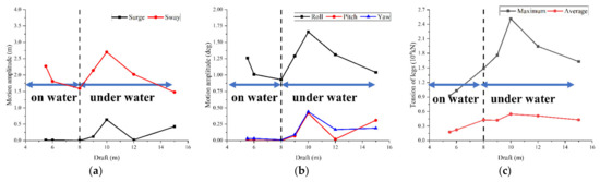
Figure 7.
Effect of draft on motion amplitude and tension on four tension legs: (a) surge and sway, (b) draft on roll, pitch, and yaw, and (c) maximum and average tension of tension leg.
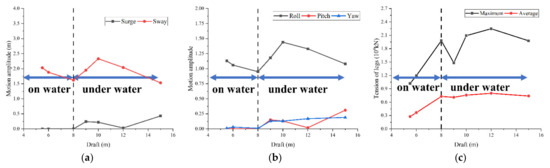
Figure 8.
Effect of draft on motion amplitude and tension on eight tension legs: (a) surge and sway, (b) draft on roll, pitch, and yaw, and (c) maximum and average tension of tension leg.
In conclusion, a draft of 8 m, which is the same as the height of the central column, is recommended. At this condition, when the central column is just submerged in seawater, the motion response of each degree of freedom is the minimum. The column with a draft of 10 m, about 1.25 times the column height, should be avoided because the motion response of each degree of freedom is the maximum. Moreover, the hydrodynamic performance of TLP-type FOWT with the new tension leg arrangement was better.
As shown in Figure 7c, when the column was above the water surface, the maximum and average tension gradually increased. With a draft of 8 m, the Moses command was used to extract all the tension of the four tension legs in the 300 s time-domain analysis, where the maximum tension was 1.488 × 10⁴ kN and the average value was 4.26 × 10³ kN. When the column was under water, the maximum and average tension increased first then decreased. When the draft was 10 m, the tension reached the maximum values, with the maximum tension of 2.513 × 10⁴ kN and average tension of 5.46 × 10³ kN at 10 m draft. As the draft increased, although the maximum tensions in Figure 8c were smaller than those in Figure 7c, the average tensions were all larger than those in Figure 7c. Therefore, the recommended breaking force of the tension leg material should be greater than 2.6 × 10⁴ kN.
3.4.2. Effect of Tension Leg Arrangement
The draft used for the analyses of different tension leg arrangements was 15 m. As shown in Figure 9, the roll of the floating body under 4 and 8 tension legs conditions was the same. As shown in Figure 10, the tension fluctuation of the p2 tension leg under different tension leg arrangements was similar. However, the tension under the 8 tension legs condition was smaller than that under the 4 tension legs condition. This indicated that the tension leg performance of TLP-type FOWT with the new tension leg arrangement was better. The stability of FOWT with inclined tension legs should also be better for the new tension leg arrangement.
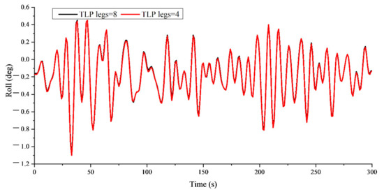
Figure 9.
Roll under different tension leg arrangements.
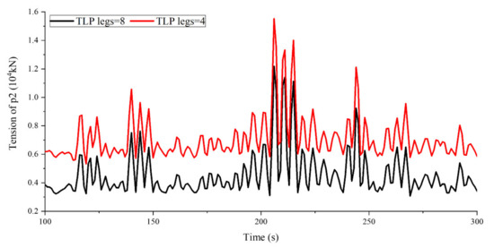
Figure 10.
Tension of p2 tension leg under different tension leg arrangements.
4. Failure Performance of Tension Legs
4.1. Failure Conditions of Tension Legs
As the performance and stability under 8 tension legs were better than for 4 tension legs, the TLP-type FOWT with a new tension leg arrangement was proposed. Then, the failure performance of tension legs for the TLP-type FOWT with the new tension leg arrangement was analyzed. The numerical models and input parameters were the same as those of Table 1, Table 2 and Table 3 in the previous section. The tension of a selected tension leg was monitored throughout the time-domain analysis using the Moses “sensor” command, and as the simulation progressed, the tension leg “action deactivate” command ran when the tension of the monitored tension leg exceeded the set allowable value of 1 × 10⁴ kN, i.e., the tension legs’ broken force, and when the tension leg was broken, there was no force.
Figure 11a shows the 8 tension legs arrangement under well operation. Figure 11b,c show the states of FOWT with inclined tension legs after one or two tension legs failed. Under these conditions, the FOWT with inclined tension legs can still maintain well operation. Figure 11d shows the state of FOWT with inclined tension legs after p1, p6, and p3 tension legs failed. Under this condition, the FOWT collapsed. Therefore, the new tension legs arrangement has good failure performance.
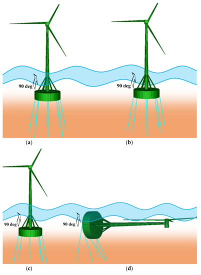
Figure 11.
Failure analysis of tension legs under the 8 tension legs condition: (a) normal, (b) failure of p1, (c) failure of p1 and p6, and (d) failure of p1, p6, and p3 (collapse).
Figure 12 shows the roll of FOWT with 8 tension legs under different failure modes. The roll after the failure of the p1 tension leg or p1 and p6 tension legs was almost the same as that under the well condition. Therefore, the failure of two tension legs has little effect on the operation of FOWT with inclined tension legs. From Figure 13, an increase of tension for the p2 tension leg was obtained under different failure modes. From Figure 14, a two-times increase of tension for the p3 tension leg was observed after the failure of p1 and p6 tension legs. Then, the more the tension legs failed, the greater the increase of tension for the adjacent tension legs was. Therefore, the operation of FOWT with inclined tension legs is risky after two tension legs fail under this environment condition. However, the FOWT with inclined tension legs still does not collapse.
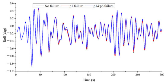
Figure 12.
Roll under different failure conditions.
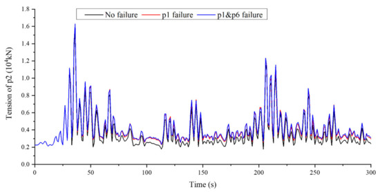
Figure 13.
p2 tension time–history curve.
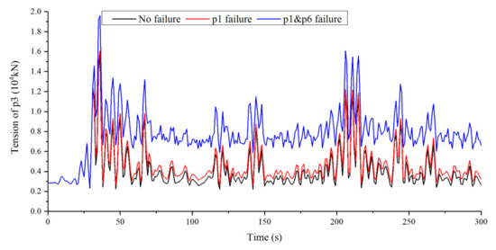
Figure 14.
p3 tension time–history curve.
As a comparison, the failure performance of the 4 tension legs arrangement under well operation was conducted. Figure 15b shows that the FOWT with inclined tension legs collapsed after the p1 tension leg failed. Therefore, the FOWT with the conventional tension leg arrangement cannot work well with any failure of tension legs when the wave incidence angle is 90 degrees.

Figure 15.
Failure analysis of tension leg under the 4 tension legs condition: (a) normal and (b) p1 failure (collapse).
4.2. Envelope Diagram of Tensions of New Tension Leg Arrangement
Figure 16 and Figure 17 summarize the maximum and average tensions of the 8 tension legs under different failure conditions. Without tension leg failure, the maximum tensions of the 8 tension legs were close. The maximum tension of p7 was the largest, 1.70542 × 10⁴ kN, and that of p4 was the smallest, 1.54101 × 10⁴ kN. In terms of the average tension, the tension of p8 was the largest, 5.0646 × 10³ kN, and that of p2 was the smallest, 3.6426 × 10³ kN.
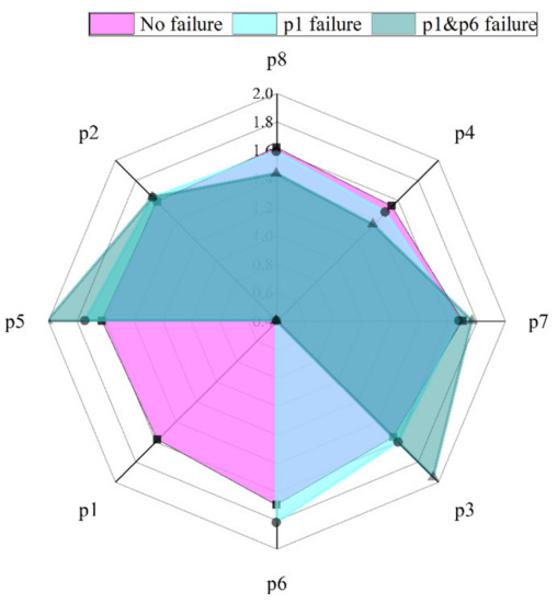
Figure 16.
Maximum tension of each tension leg (unit: 104 kN).
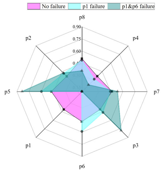
Figure 17.
Average tension of each tension leg (unit: 104 kN).
When p1 failed, the maximum tension of p5 and p6 increased, which were nearest to p1. The maximum tension of p5 increased by 1.1958 × 10³ kN, an increment of 7.4%. That of p6 increased by 1.2362 × 10³ kN, an increment of 7.3%. At the same time, the maximum tensions of p4, p7, and p8 decreased. The maximum tension of p4, which is opposite to p1, reduced by 3.9%. When p1 and p6 tension legs failed, the maximum tensions of p3 and p5, nearest to p1 and p6, largely increased, by 3.9935 × 10³ and 3.8448 × 10³ kN, respectively. The maximum tensions of p4 and p8, opposite to p1 and p6, decreased. A similar trend can be observed for the average tension of tension legs under different failure modes. When p1 and p6 failed, the adjacent tension legs achieved large average tensions.
When one tension leg failed, the maximum and average tension did not change too much. The FOWT with the new tension leg arrangement can still remain in good operation. When two adjacent tension legs failed, the maximum and average tension of adjacent tension legs greatly increased. However, the FOWT can still operate. There is a risk of collapsing, and therefore some improvement methods need to be performed in time. In conclusion, the FOWT with the new tension leg arrangement has good failure performance and the ability to withstand environmental loads.
5. Conclusions
A hydrodynamic model was applied to analyze the hydrodynamic response of FOWT with inclined tension legs. Failure performance of tension legs was conducted under conventional and new tension leg arrangements. The specific conclusions of this paper can be summarized as follows:
(1) The effects of draft and tension leg arrangement were analyzed. The draft of 8 m, which is the same as the height of the column, is proposed due to the optimum performance of FOWT with inclined tension legs. Compared with the conventional tension leg arrangement, the new tension leg arrangement was subjected to lower tensions. Therefore, the performance of FOWT with the new tension leg arrangement was better.
(2) Based on the tension analyses of FOWT with inclined tension legs under different drafts, it is recommended that the breaking force of the tension leg material should be greater than 2.6 × 10⁴ kN.
(3) The stability of FOWT with the new tension leg arrangement after single or double tension leg failure was largely improved. The FOWT with the new tension leg arrangement had good failure performance and the ability to withstand environmental loads.
(4) Although the FOWT with inclined tension legs could still operate after two tension legs failed, there is a risk of collapsing. Therefore, some improvement methods need to be performed in time.
Author Contributions
Conceptualization, Z.J. and X.L.; methodology, Z.J. and X.L.; software, J.L. and W.L; validation, Z.J., H.W. and H.C.; formal analysis, H.C.; investigation, H.W.; resources, J.L. and S.H.; data curation, Z.J.; writing—original draft preparation, Z.J.; writing—review and editing, X.L.; visualization, X.Z. and W.L.; supervision, X.L.; project administration, Q.Z. All authors have read and agreed to the published version of the manuscript.
Funding
This research was funded by the State Key Laboratory of Hydraulic Engineering Simulation and Safety (Tianjin University) (Grant No. HESS-2115), and the Natural Science Foundation of Hebei Province (Grant No. E2020402110).
Data Availability Statement
Not applicable.
Conflicts of Interest
The authors declare no conflict of interest.
References
- Leung, D.Y.C.; Yang, Y. Wind energy development and its environmental impact: A review. Renew. Sust. Energ. 2012, 16, 1031–1039. [Google Scholar] [CrossRef]
- Kumar, Y.; Ringenberg, J.; Depuru, S.S.; Devabhaktuni, V.K.; Lee, J.W.; Nikolaidis, E.; Andersen, B.; Afjeh, A. Wind energy: Trends and enabling technologies. Renew. Sust. Energ. 2016, 53, 209–224. [Google Scholar] [CrossRef]
- Ren, Y.; Venugopal, V.; Shi, W. Dynamic analysis of a multi-column TLP floating offshore wind turbine with tendon failure scenarios. Ocean. Eng. 2022, 245, 110247. [Google Scholar] [CrossRef]
- Walia, D.; Schünemann, P.; Hartmann, H.; Adam, F.; Groβmann, J. Numerical and physical modeling of a tension-leg platform for offshore wind turbines. Energies 2021, 14, 3554. [Google Scholar] [CrossRef]
- Ma, Z.; Wang, S.; Wang, Y.; Ren, N.; Zhai, G. Experimental and numerical study on the multi-body coupling dynamic response of a Novel Serbuoys-TLP wind turbine. Ocean. Eng. 2019, 192, 106570. [Google Scholar] [CrossRef]
- Ma, Z.; Ren, N.; Wang, Y.; Wang, S.; Shi, W.; Zhai, G. A Comprehensive study on the serbuoys offshore wind tension leg platform coupling dynamic response under typical operational conditions. Energies 2019, 12, 2067. [Google Scholar] [CrossRef]
- Song, J.; Lim, H.C. Study of Floating Wind Turbine with Modified Tension Leg Platform Placed in Regular Waves. Energies 2019, 12, 703. [Google Scholar] [CrossRef]
- Zhao, Y.; She, X.; He, Y.; Yang, J.; Peng, T.; Kou, Y. Experimental study on new multi-column tension-leg-type floating wind turbine. China. Ocean. Eng. 2018, 32, 123–131. [Google Scholar] [CrossRef]
- Ha, K.; Truong, H.V.A.; Dang, T.D.; Ahn, K.K. Recent control technologies for floating offshore wind energy system: A review. Int. J. Pr. Eng. Man-Gt. 2021, 8, 281–301. [Google Scholar] [CrossRef]
- Cruz, A.M.; Krausmann, E. Damage to offshore oil and gas facilities following hurricanes Katrina and Rita: An overview. J. Loss Prev. Proc. 2008, 21, 620–626. [Google Scholar] [CrossRef]
- Yang, C.K.; Kim, M.H. Transient effects of tendon disconnection of a TLP by hull-tendon-riser coupled dynamic analysis. Ocean. Eng. 2010, 37, 667–677. [Google Scholar] [CrossRef]
- Jameel, M.; Oyejobi, D.O.; Siddiqui, N.A.; Sulong, N.H.R. Nonlinear dynamic response of tension leg platform under environmental loads. KSCE J. Civ. Eng. 2017, 21, 1022–1030. [Google Scholar] [CrossRef]
- Oyejobi, D.O.; Jameel, M.; Sulong, N.H.R. Nonlinear response of tension leg platform subjected to wave, current and wind forces. Int. J. Civ. Eng. 2016, 14, 521–533. [Google Scholar] [CrossRef]
- Oyejobi, D.O.; Jameel, M.; Sulong, N.H.R. Stochastic response of intact and a removed tendon tension leg platform to random wave and current forces. Arab. J. Sci. Eng. 2017, 42, 1065–1076. [Google Scholar] [CrossRef]
- Tabeshpour, M.R.; Ahmadi, A.; Malayjerdi, E. Investigation of TLP behavior under tendon damage. Ocean. Eng. 2018, 156, 580–595. [Google Scholar] [CrossRef]
- Yu, J.; Hao, S.; Yu, Y.; Chen, B.; Cheng, S.; Wu, J. Mooring analysis for a whole TLP with TTRs under tendon one-time failure and progressive failure. Ocean. Eng. 2019, 182, 360–385. [Google Scholar] [CrossRef]
- Wu, H.; Zhao, Y.; He, Y.; Shao, Y.; Mao, W.; Han, Z.; Huang, C.; Gu, X.; Jiang, Z. Transient response of a TLP-type floating offshore wind turbine under tendon failure conditions. Ocean. Eng. 2021, 220, 108486. [Google Scholar] [CrossRef]
- Cheng, S.; Yu, Y.; Yu, J.; Wu, J.; Li, Z.; Huang, Z. Mechanistic research on the complex motion response of a TLP under tendon breakage. Ocean. Eng. 2021, 240, 109984. [Google Scholar] [CrossRef]
- Qi, Y.; Tian, X.; Guo, X.; Lu, H.; Liu, L. The hydrodynamic performance of a tension leg platform with one-tendon failure. Ships. Offshore. Struc. 2018, 14, 523–533. [Google Scholar] [CrossRef]
- Chung, W.C.; Pestana, G.R.; Kim, M. Structural health monitoring for TLP-FOWT (floating offshore wind turbine) tendon using sensors. Appl. Ocean. Res. 2021, 113, 102740. [Google Scholar] [CrossRef]
- Choi, Y.-M.; Nam, B.W.; Hong, S.Y.; Jung, D.W.; Kim, H.J. Coupled motion analysis of a tension leg platform with a tender semi-submersible system. Ocean. Eng. 2018, 156, 224–239. [Google Scholar] [CrossRef]
- Jeon, S.H.; Cho, Y.U.; Seo, M.W.; Cho, J.R.; Jeong, W.B. Dynamic response of floating substructure of spar-type offshore wind turbine with catenary mooring cables. Ocean. Eng. 2013, 72, 356–364. [Google Scholar] [CrossRef]
- Koo, B.J.; Goupee, A.J.; Kimball, R.W.; Lambrakos, K.F. Model tests for a floating wind turbine on three different floaters. J. Offshore. Mech. 2014, 136, 020907. [Google Scholar] [CrossRef]
- Wu, Z.; Li, Y. Platform stabilization of floating offshore wind turbines by artificial muscle based active mooring line force control. IEEE ASME T. Mech. 2020, 25, 2765–2776. [Google Scholar] [CrossRef]
- Bae, Y.H.; Kim, M.H.; Kim, H.C. Performance changes of a floating offshore wind turbine with broken mooring line. Renew. Energ. 2017, 101, 364–375. [Google Scholar] [CrossRef]
- Li, Y.; Zhu, Q.; Liu, L.; Tang, Y. Transient response of a SPAR-type floating offshore wind turbine with fractured mooring lines. Renew. Energ. 2018, 122, 576–588. [Google Scholar] [CrossRef]
- Le, C.; Li, Y.; Ding, H. Study on the coupled dynamic responses of a submerged floating wind turbine under different mooring conditions. Energies 2019, 12, 418. [Google Scholar] [CrossRef]
- Yang, Y.; Bashir, M.; Li, C.; Wang, J. Investigation on mooring breakage effects of a 5 MW barge-type floating offshore wind turbine using F2A. Ocean. Eng. 2021, 233, 108887. [Google Scholar] [CrossRef]
- Ahmed, M.O.; Yenduri, A.; Kurian, V.J. Evaluation of the dynamic responses of truss spar platforms for various mooring configurations with damaged lines. Ocean. Eng. 2016, 123, 411–421. [Google Scholar] [CrossRef]
- Yang, Y.; Bashir, M.; Michailides, C.; Mei, X.; Wang, J.; Li, C. Coupled analysis of a 10 MW multi-body floating offshore wind turbine subjected to tendon failures. Renew. Energ. 2021, 176, 89–105. [Google Scholar] [CrossRef]
- Sakaris, C.S.; Bashir, M.; Yang, Y.; Michailides, C.; Wang, J.; Sakellariou, J.S. Diagnosis of damaged tendons on a 10 MW multibody floating offshore wind turbine platform via a response-only functional model based method. Eng. Struct. 2021, 242, 112384. [Google Scholar] [CrossRef]
- Sakaris, C.S.; Yang, Y.; Bashir, M.; Michailides, C.; Wang, J.; Sakellariou, J.S.; Li, C. Structural health monitoring of tendons in a multibody floating offshore wind turbine under varying environmental and operating conditions. Renew. Energ. 2021, 179, 1897–1914. [Google Scholar] [CrossRef]
- Wang, T.; Jin, H.; Wu, X. Coupled dynamic analysis of a tension leg platform floating offshore wind turbine. J. Offshore Mech. Arct. 2020, 142, 011901. [Google Scholar] [CrossRef]
- Wei, N.; Zhang, Z.; Xu, X.; Yao, W. Stability analysis of a TLP with inclined tension legs under different marine survival conditions. J. Mar. Sci. Eng. 2022, 10, 1058. [Google Scholar] [CrossRef]
- Milano, D.; Peyrard, C.; Capaldo, M.; Ingram, D.; Xiao, Q.; Johanning, L. Impact of high order wave loads on a 10 MW tension-leg platform floating wind turbine at different tendon inclination angles. In Proceedings of the ASME 2019 38th International Conference on Ocean, Offshore and Arctic Engineering: Volume 10 Ocean Renewable Energy, Glasgow, Scotland, UK, 9–14 June 2019; ASME: New York, NY, USA, 2019; p. V010T09A076. [Google Scholar] [CrossRef]
- Hasselmann, K.; Barnett, T.P.; Bouws, E.; Carlson, H.; Cartwright, D.E.; Enke, K.; Ewing, J.A.; Gienapp, H.; Hasselmann, D.E.; Kruseman, P.; et al. Measurements of wind-wave growth and swell decay during the Joint North Sea Wave Project (JONSWAP). Deut. Hydrogr. Z. 1973, 8, 1–95. [Google Scholar]
- Manual, M. Moses Pdf. 2009. Available online: http://www.ultramarine.com/hdesk/document/ref_man.htm (accessed on 1 August 2020).


Publisher’s Note: MDPI stays neutral with regard to jurisdictional claims in published maps and institutional affiliations. |
© 2022 by the authors. Licensee MDPI, Basel, Switzerland. This article is an open access article distributed under the terms and conditions of the Creative Commons Attribution (CC BY) license (https://creativecommons.org/licenses/by/4.0/).