Article

A 5.8 GHz π-Stub Decoupling Network for Receiving Antenna Arrays in Microwave Wireless Power Transmission

School of Electrical Engineering, Chongqing University, Chongqing 400044, China
*
Author to whom correspondence should be addressed.
Energies 2022, 15(22), 8703; https://doi.org/10.3390/en15228703
Submission received: 27 October 2022 / Revised: 15 November 2022 / Accepted: 17 November 2022 / Published: 19 November 2022
(This article belongs to the Special Issue Advances in Wireless Power Transfer System)

Abstract

:
In this paper, a 5.8 GHz π-stub decoupling network is proposed to improve the performance of a receiving antenna array (RAA) in microwave wireless power transmission (MWPT) systems. A set of general design formulas was derived for determining the electric parameters of the required π-stubs. To validate the new technique, a π-stub decoupling network was combined with RAAs. The simulated and measured results show that the performance of the RAA is greatly improved by loading the π-stub decoupling network. In addition, a miniaturized MWPT system was built. System-level measurements indicate that the novel decoupling network enhances the receiving power of the RAA by up to 36.4%. An extended application also shows the scalability and effectiveness of the network, implying its huge potential in large-scale receiving arrays.

1. Introduction

Since microwave wireless power transmission (MWPT) was proposed in 1968 [1], it has received a lot of attention. The advantages of not requiring a transmission line and having flexibility [2] enable it to be applied in many special conditions, such as multi-target and moving target power supply, isolated island power supply, etc. [3,4,5,6]. The receiving antenna array (RAA) plays a crucial role in the MWPT system, and its performance directly determines the overall efficiency. Usually, the microstrip antenna array is widely used as the RAA because of its light weight, small volume, and easy integration. The receiving efficiency of RAAs can be improved by expanding the effective area or increasing the gain [7]. Without significantly enlarging the antenna volume, the increase in the RAA area and gain will further compress the gaps between the elements in the array. In addition, the limited space constraint and the trend of miniaturization also require the element gap to be sufficiently small. Some typical examples of RAAs are shown in Table 1.
When the gap is less than λ/2, a strong coupling will be generated between the elements, which is harmful to the impedance matching, radiation direction, and gain of the array. So, it is crucial to consider the effect of coupling when designing RAAs. In recent years, various methods have been developed in research on reducing mutual coupling. In [8,9,10], some electromagnetic bandgap (EBG) structures were presented. However, this kind of structure is not suitable for RAAs because the EBGs themselves occupy too much space. In [11], a defected ground structure (DGS) was proposed. The DGS could introduce a current redistribution to decrease the mutual coupling, but the radiation patterns could deteriorate [12]. In addition, there are neutralization lines [13,14,15], decoupling metasurfaces [16,17], decoupling networks [18,19], etc. Among these methods, decoupling networks are superior due to their simple structure, the adaptability of their design principles, and their flexible element gaps [20]. However, according to Table 1, most of the present MWPT systems ignore the coupling problem of RAAs. Since they did not address the effect of mutual coupling, the negative effect of mutual coupling on receiving power is unknown.
Table 1. A few typical RAAs in MWPT systems.
ReferenceFrequency (GHz)Size (m)SpacingConsideration of Coupling Effects
[2]5.7~6.30.07 × 0.07<0.36 λNo
[21]5.81 × 10.22 λNo
[22]5.81.38 × 1.380.35 λNo
[23]5.80.5 × 0.50.19 λNo
This study applied decoupling techniques to RAAs for the first time and proposed a 5.8 GHz π-stub decoupling network for MWPT to improve the receiving power of the RAAs. In Section 2, the design principle and formula of the π-stub decoupling network are presented. Section 3 proposes an antenna array, and the application of the decoupling network to the antenna array is described to verify its decoupling effect. Section 4 presents a miniaturized MWPT experimental system built to compare the difference in receiving power before and after decoupling. Section 5 presents an extended application of the π-stub decoupling network. Finally, conclusions are given in Section 6.

2. Design of the Decoupling Network

Considering that the π-stub decoupling network can provide a wider decoupling bandwidth, it is highly suitable for RAAs [24]. As shown in Figure 1a, the proposed π-stub decoupling network is connected in parallel with the coupled antenna network.
It is assumed that the admittance matrix of the two coupled antennas and the decoupling network are represented by [ Y A ] and [ Y D ], respectively. Then, the total admittance of the decoupled antennas is the sum of the two matrices, as shown in (1).
Y = [ Y 11 Y 12 Y 13 Y 14 ] = [ Y 11 A + Y 11 D Y 12 A + Y 12 D Y 21 A + Y 21 D Y 22 A + Y 22 D ]
For an ideal well-matched two-port network, the S-matrix of all elements should be equal to 0, so the normalized Y-matrix after the S-Y transformation is
Y = [ 1 0 0 1 ]
When (1) is equal to (2), antennas can reach high isolation and are well-matched after loading the decoupling network. It is worth noting that [ Y D ] is a purely imaginary matrix because the decoupling network is lossless. Set (1) is equal to (2), so then the decoupling conditions can be obtained:
j Im [ Y 21 A ] + Y 21 D = 0
Re [ Y 21 A ] = 0
The matching conditions are:
j Im [ Y 11 A ] + Y 11 D = 0
Re [ Y 11 A ] = 1
where (3) is the decoupling target, and (4) shows no power loss due to coupling when the original coupled antenna is working. Condition (5) requires that the self-admittance of the decoupling network be able to counteract that of the coupled array, and (6) shows that the original coupled antenna is well matched. Since the original antenna is symmetric, only Y11 and Y21 are considered. In summary, when the decoupling network reaches the requirements of (3)–(6), high isolation can be achieved.
Figure 1b shows the proposed π-stub decoupling network and its equivalent circuit, where Z1, θ1, Z2, and θ2 are the characteristic impedance and electrical length of the corresponding stubs at 5.8 GHz. The ABCD matrix of the π-stub network is
[ A j B j C D ] = [ 1 0 j tan θ 1 Z 1 1 ] × [ cos θ 2 j Z 2 sin θ 2 j sin θ 2 Z 2 cos θ 2 ] × [ 1 0 j tan θ 1 Z 1 1 ] = [ cos θ 2 Z 2 sin θ 2 tan θ 1 Z 1 j Z 2 sin θ 2 j ( 2 cos θ 2 tan θ 1 Z 1 + sin θ 2 Z 2 Z 2 sin θ 2 tan 2 θ 1 Z 1 2 ) cos θ 2 Z 2 sin θ 2 tan θ 1 Z 1 ]
Comparing the entries of the ABCD matrix with the corresponding entries of the equivalent circuit, the following equations can be obtained.
{ cos θ 2 Z 2 sin θ 2 tan θ 1 Z 1 = cos θ t Z 2 sin θ 2 = Z t sin θ t 2 cos θ 2 tan θ 1 Z 1 + sin θ 2 Z 2 Z 2 sin θ 2 tan 2 θ 1 Z 1 2 = tan θ t Z t
This can be simplified to
2 cos θ 2 cos θ 2 cos θ t Z t sin θ t + sin θ 2 Z 2 Z 2 sin θ 2 ( cos θ 2 cos θ t Z t sin θ t ) 2 = tan θ t Z t
tan θ 1 Z 1 = cos θ 2 cos θ t Z t sin θ t
Zt and θt are predefined parameters, and Equation (9) contains only Z2 and θ2. Hence, θ1 and θ2 can be calculated by choosing the appropriate Z1 and Z2. According to (10), the π-stub decoupling network can be designed, which has a good match with RAAs.

3. Application to RAAs

3.1. The 1 × 2 RAA

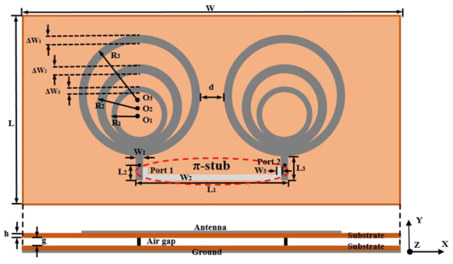
In order to demonstrate the effect of the π-stub decoupling network, a pair of 5.8 GHz RAAs were designed, simulated, and measured. The 1 × 2 RAA resonated at 5.8 GHz and was designed on a polyimide with a thickness of 0.1 mm (εr = 3.5, tan σ = 0.002), and a 1 mm air gap was set for better impedance matching. The edge-to-edge distance of the antenna was 6 mm (0.11 λ0). The antenna geometry and parameters are shown in Figure 2 and Table 2.
In order to solve the specific parameters of the required π-stub decoupling network, the equivalent circuit needs to be obtained first. It is known that a length of transmission line can act as a phase converter, and once it is added in the proper position, the transmission current can offset the coupling one. Therefore, a meander line can be attached between the two microstrip lines for decoupling purposes. Here, considering that the original array is well matched, conditions (4) and (6) are satisfied, and (5) can be achieved by selecting the proper L2. Hence, (3) is considered the optimization goal.
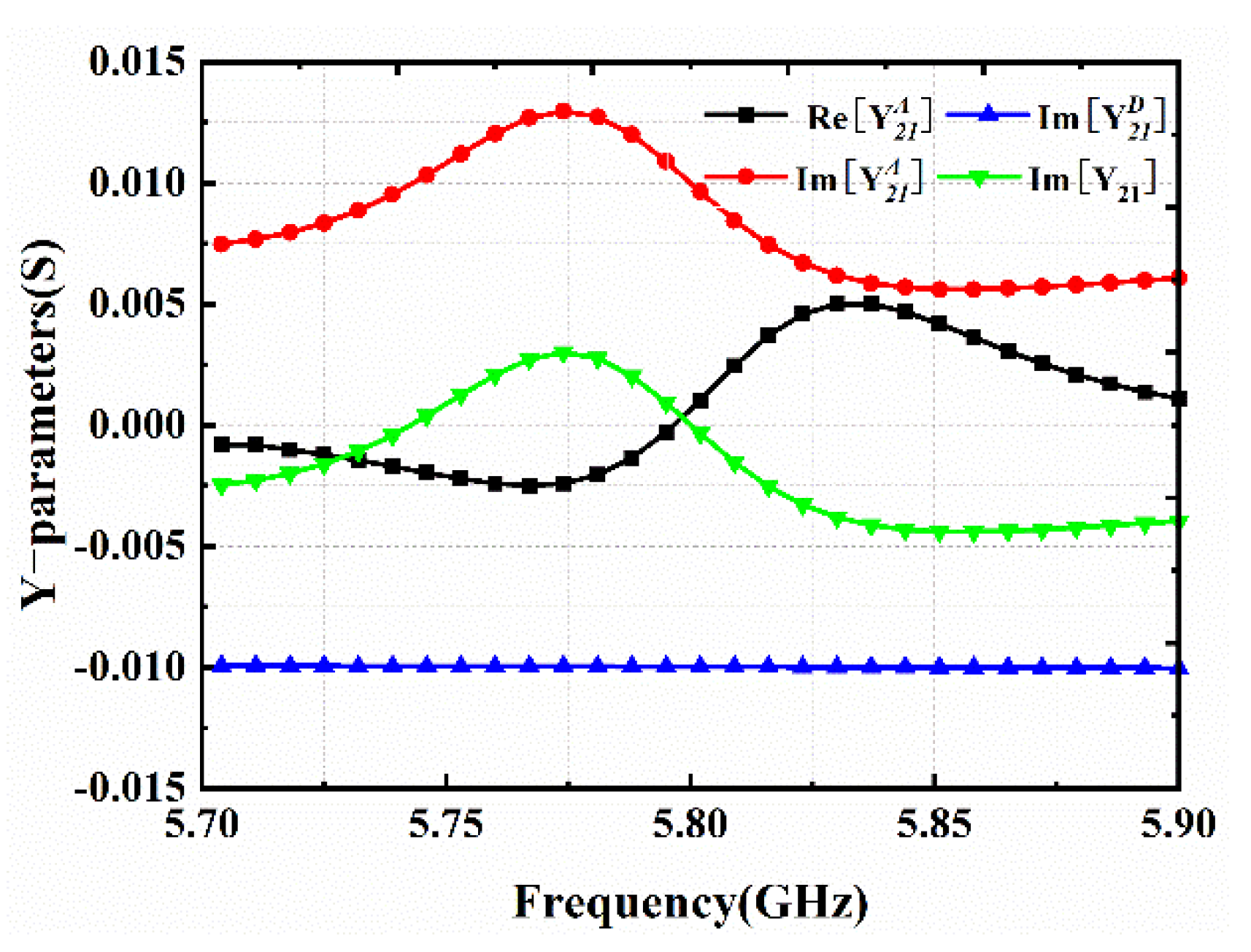
Figure 3 shows the relevant Y parameters for (3) and (4). It is clearly seen that at 5.8 GHz, the real part of Y 21 A is close to 0, and the imaginary part is offset from the imaginary part of Y 21 D . Therefore, according to the simulation in CST, it can be determined that the meander line can effectively decouple the 1 × 2 RAA at a length of 33.2 mm and a width of 0.41 mm.
Thus, the parameters of the equivalent circuit can be determined as Zt = 172.6 Ω and θt = 232.4°. However, the complex structure of the meander line imposes constraints on the element gaps and takes up more space, with little potential for larger arrays. Instead, the simple structure of the π-stub decoupling network is convenient for integration. According to the π-stub design formula and choosing Z1 = Z2 = 50 Ω, we can obtain θ1 = 4.97° and θ2 = 148.87°. The designed decoupling network is shown in Figure 2.
The related simulation results are shown in Figure 4. It can be seen that the original RAA coupling coefficient at 5.8 GHz is −15.1 dB. The mutual coupling decreases by 10.5 dB when the meander line takes effect, while the mutual coupling decreases by 16.7 dB when the π-stub decoupling network is added, and S11 decreases from −11 dB to −27 dB.
Moreover, the decoupling effect of the π-stub network can be understood by the surface current distribution. When port 1 is excited, the coupled element is strongly influenced, but it is obvious that the coupled current is greatly weakened after loading the π-stub decoupling network, as shown in Figure 5.
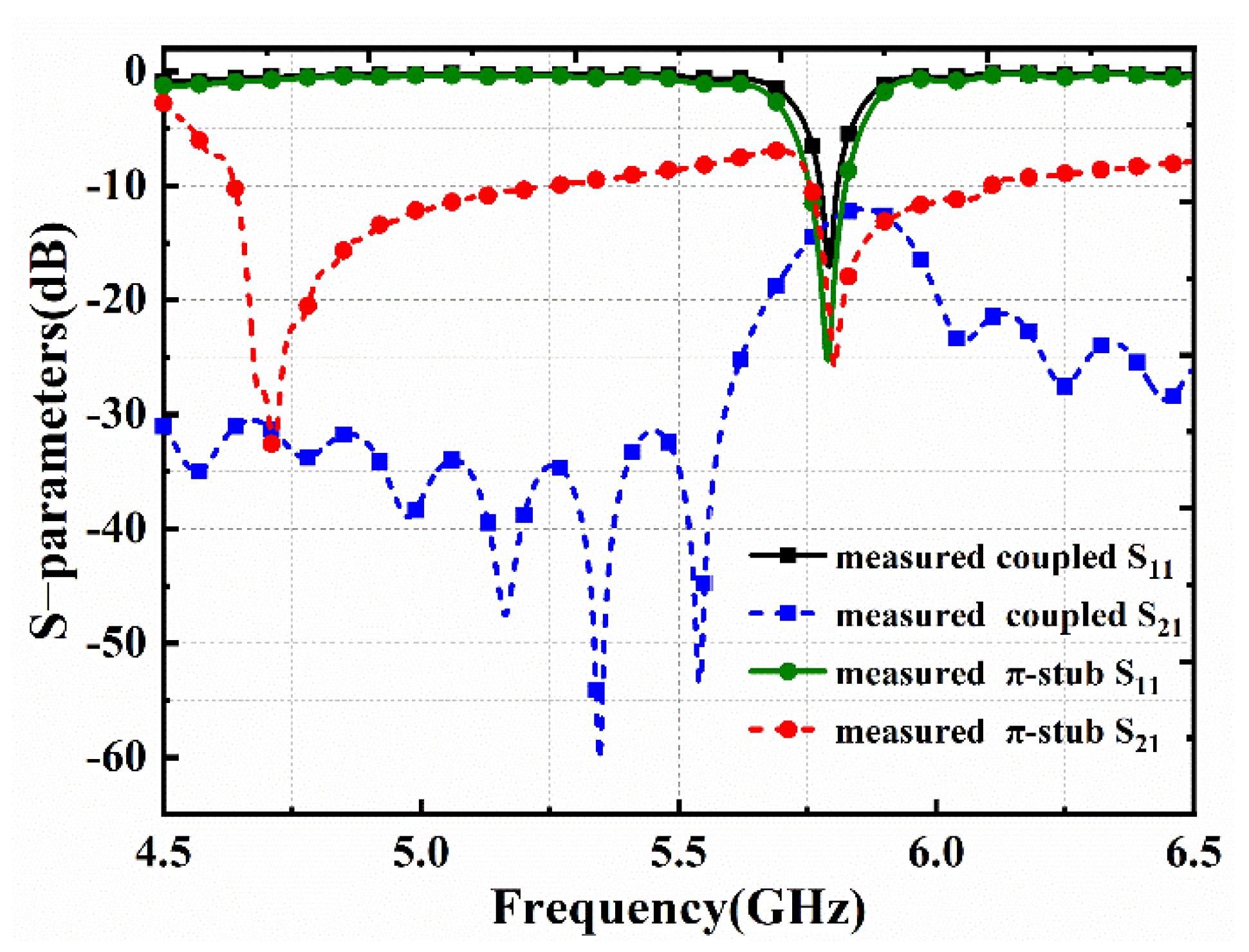
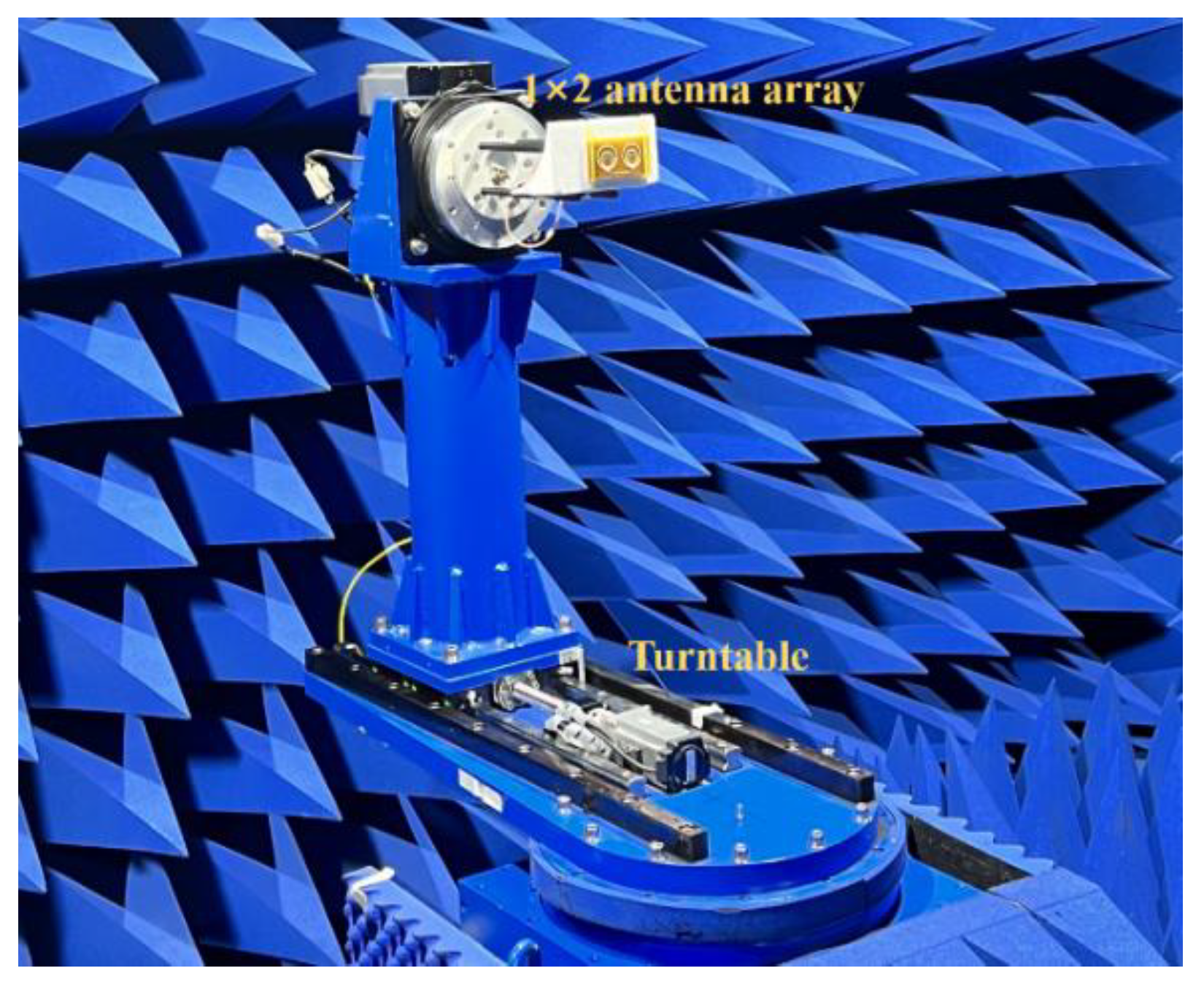
To prove the application value, the antennas were fabricated and measured. The prototypes are shown in Figure 6. The air gap is replaced by PMI (Polymethacrylimide, εr = 1.02). The S−parameters were measured using an R&S ZVA-50 vector network analyzer, and the results are shown in Figure 7. It can be seen that S11 at 5.8 GHz decreases from −12.1 dB to −17.9 dB, achieving a better match. It is evident that due to the π-stub, a 15.3 dB mutual coupling reduction is achieved. The measured and simulated results are in good agreement. In addition, the antenna radiation patterns were measured by using a DONGSHIN ISPACE-6000 microwave anechoic chamber. When port 1 is excited, port 2 is terminated with a matching load. The measurement setup is shown in Figure 8.
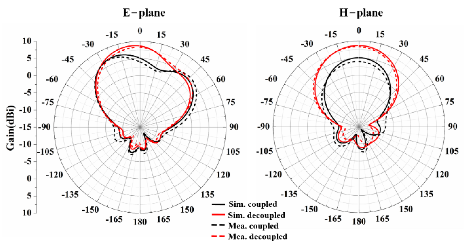
According to Figure 9, it can be clearly seen that, before decoupling, the radiation patterns are seriously distorted because the coupled current excites the radiation of other patches, leading to poor directionality and gain reduction. This has very negative effects on the receiving power. However, the antenna’s directionality and gain are greatly improved after loading the π-stub. Specifically, port 1 has a maximum measured gain of 5.5 dBi when coupled and 8.3 dBi when decoupled, showing that the π-stub is effective in decoupling the 1 × 2 RAA.
According to the comparison with other decoupled antennas shown in Table 3, the proposed π-stub decoupling network can provide good isolation at a center-to-center spacing of 0.39 λ. Moreover, the π-stub is designed to improve the receiving power of RAAs in MWPT systems, and the effectiveness is validated in Section 4.

3.2. The 2 × 2 RAA

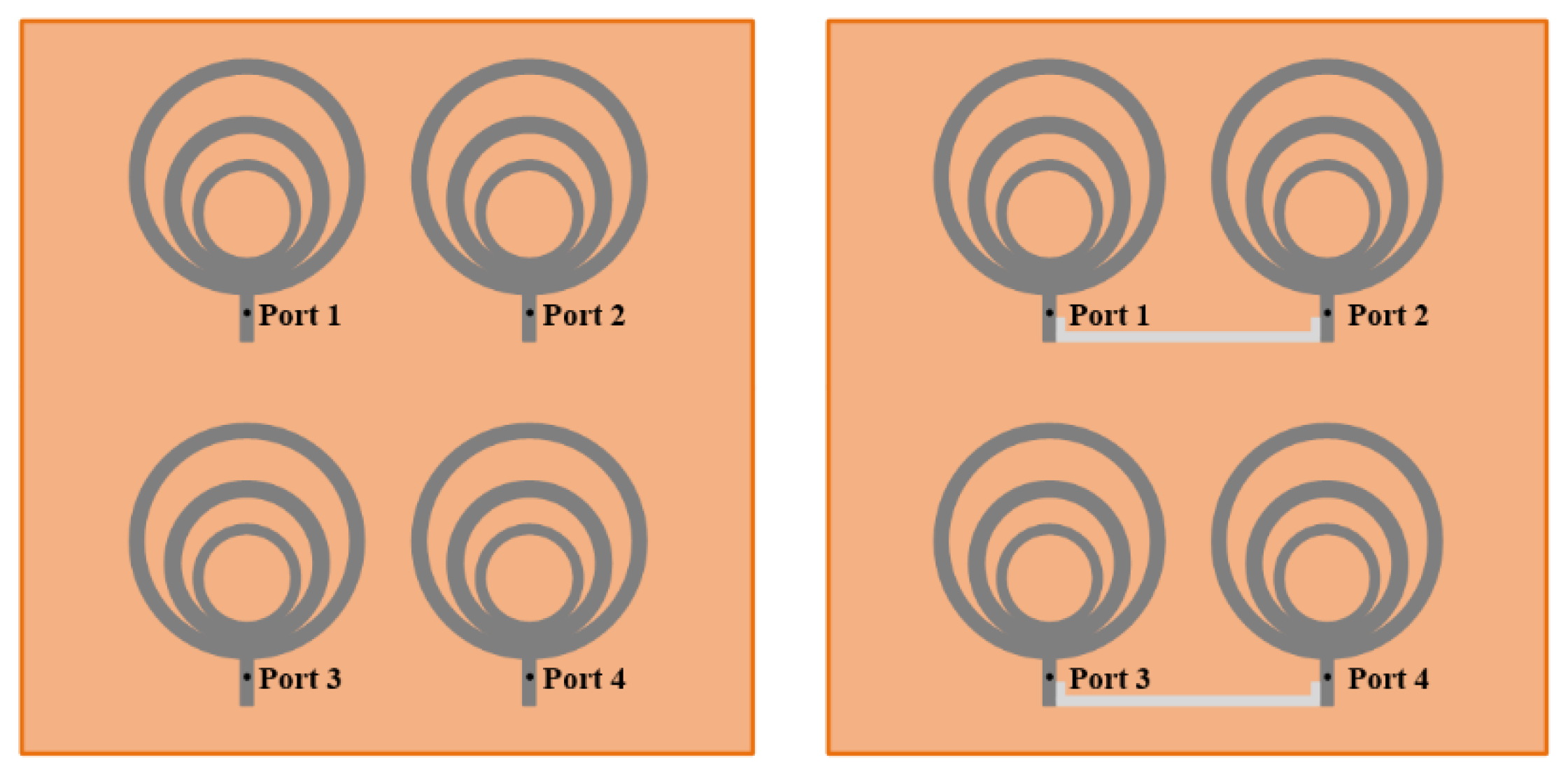
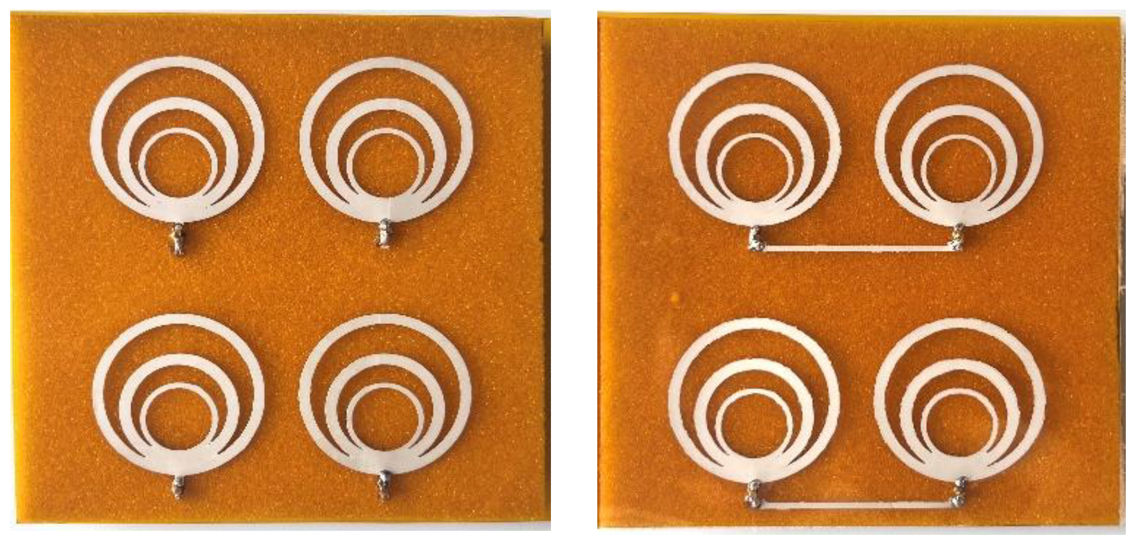
RAAs for MWPT are often fabricated as rectangular arrays to expand the receiving area, so the 1 × 2 RAA was extended into a 2 × 2 RAA, as shown in Figure 10. The distance between the horizontal elements is still 0.11 λ, and the vertical distance is 0.62 λ, so the mutual coupling between port 1 and port 3 is ignorable. Due to the symmetry of the antenna, only port 1 and port 3 need to be considered. Figure 11 shows the simulated and measured S−parameter results.
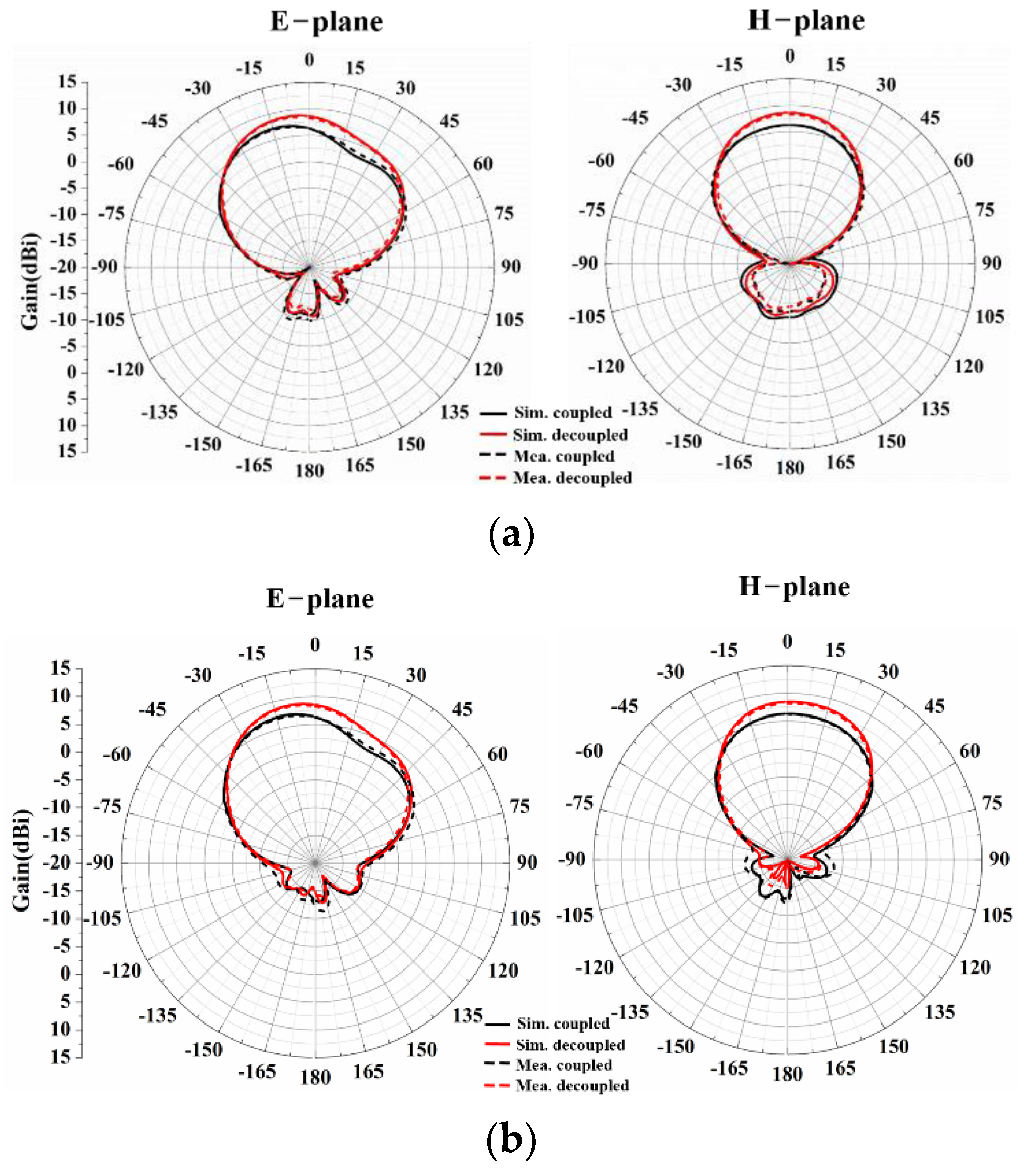
It can be observed that the coupling is greatly reduced by adding the π-stub to the 2 × 2 RAA. The simulated mutual coupling reductions in adjacent elements S21 and S34 reach 13.9 and 12.7 dB, respectively, while the measured ones are 14.3 and 13.4 dB. In addition, simulated and measured radiation patterns of the coupled RAA and the decoupled RAA are shown in Figure 12. When simulated and measured, only the corresponding port is excited, and the other ports are terminated with matching loads. It can be seen that the gain after decoupling is significantly higher than that of the coupled antenna. The higher gain is more favorable for the receiving power. This will be demonstrated in the MWPT experiment.

4. MWPT Experiment

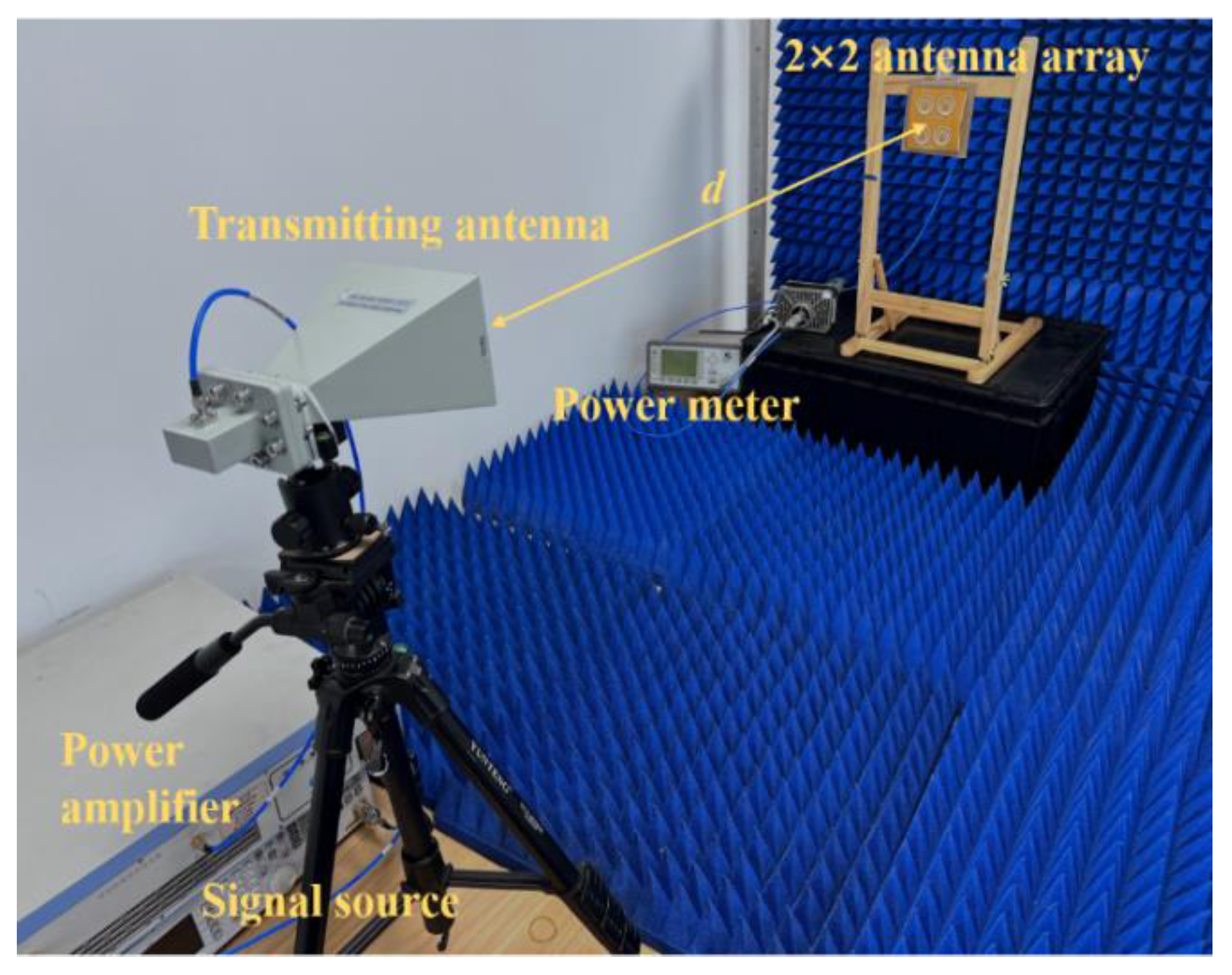
A miniaturized MWPT system was built to verify the value of the proposed π-stub in the MWPT application. The experimental system is shown in Figure 13.
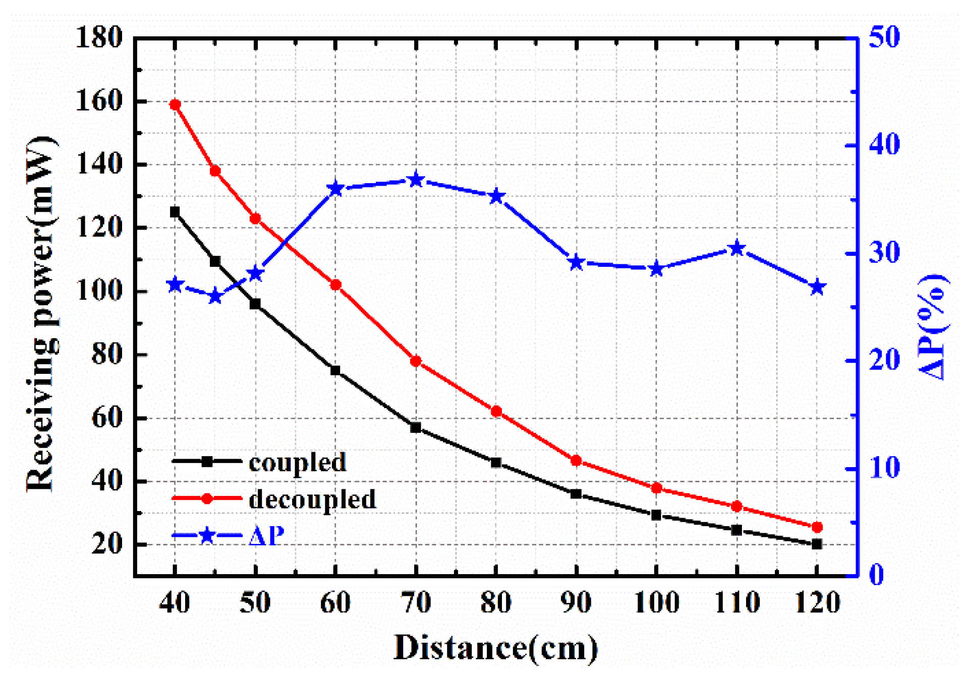
In the experiment, a 5.8 GHz signal was generated by a signal source and amplified by a power amplifier. The transmitting antenna was a 5.8 GHz horn with a gain of 16 dBi. The input power of the transmitting antenna was 2 W, and the 2 × 2 RAA was placed at different positions (within the near-field range) to measure its receiving power. The geometric centers of the transmitting and receiving antennas were always aligned. The measured results are shown in Figure 14.
Δ P = P with _ π stub P without _ π stub P without _ π stub
The improvement in receiving power is denoted by ΔP, where P with _ π stub is the measured power when the antenna array adds the proposed π-stub, and P without _ π stub is the measured power when there is no π-stub in the antenna array. Obviously, in the range from 40 cm to 120 cm, the addition of the π-stub leads to a maximum enhancement of 36.4% of receiving power. The measured results are reduced when the RAA approaches the far-field region, which is mainly due to the power loss in free space. It is noteworthy that the improvement was maintained at more than 27% in the entire range.

5. Extended Applications

As the RAA continues to expand, too many ports will lead to high costs. So, the feed network needs to be designed to reduce the number of output ports. In this case, the proposed π-stub can be regarded as a parasitic structure combined with the feed network to improve the performance of the RAA. This can be proved by experimental results. The feed network needs to achieve good impedance matching and ensure an equal transmission phase, as shown in Figure 15. It is worth noting that, in order to combine with the feed network, π-stub 2 is rotated by 180°, and the antenna elements remain parallel to the π-stub. The feed network changes the antenna impedance matching, so the geometry of the antenna part is fine-tuned. The relevant parameters are shown in Table 4.
The prototypes were made and measured. Ant. A is the original RAA, and Ant. B has an added π-stub, as shown in Figure 16. According to the results in Figure 17, S11 of Ant. A and Ant. B at 5.8 GHz is −12.3 dB and −21.8 dB, respectively, indicating that Ant. B has better impedance matching. For the RAA, less power is reflected to free space.
Then, the radiation patterns were also simulated and measured, as shown in Figure 18. The results show that the radiation patterns of Ant. A and Ant. B do not produce undesirable deformation, while the gain of Ant. B is higher than that of Ant. A. The gains of Ant. A and B are 11.6 and 13 dBi, respectively. Obviously, the addition of the π-stub improves the impedance matching of the RAA and increases the gain. To further validate the results, Ant. A and Ant. B were measured using the MWPT experimental system.
From the curve in Figure 19, it can be clearly seen that Ant B has a maximum of 32.3% improvement in receiving power capability. The overall results are reduced compared to Figure 14, which is caused by losses in the feed network. However, more than 17% improvement is still maintained over the entire range, verifying the scalability of the proposed π-stub.

6. Conclusions

This study applied a decoupling network to RAAs in MWPT for the first time. The design principle and implementation form of the network were derived and combined with some specific RAAs. Compared with other decoupled structures, the proposed π-stub decoupling network can provide good isolation. Moreover, the measured results show that the proposed π-stub decoupling network can greatly improve the performance of the RAAs, including impedance matching, isolation, and gain. In addition, MWPT experiments were conducted, and the results show that the π-stub network can enhance the receiving power by up to 36.4%. Finally, the scalability of the π-stub was demonstrated by extending it to the feed network. The gain of the improved RAA is increased by 1.4 dBi with a maximum enhancement of 32.3% in receiving power. It is predicted that the proposed π-stub decoupling network will help to receive more power when the RAA is larger. Therefore, this novel decoupling network has a huge potential in high-power long-range MWPT systems.

Author Contributions

Proposed the main idea: X.L.; discussed the results and checked the whole manuscript: W.P.; contributed to the discussion of this study: H.X., H.Z. and Z.L. All authors have read and agreed to the published version of the manuscript.

Funding

This work was supported by the Chengdu-Chongqing Double-City Economic Circle construction technology innovation project under Grant KJCXZD2020001.

Data Availability Statement

The data used to support the findings of this study are included within the article.

Conflicts of Interest

The authors declare no conflict of interest.

References

  1. Brown, W.C. The History of Power Transmission by Radio-Waves. IEEE Trans. Microw. Theory Tech. 1984, 32, 1230–1242. [Google Scholar] [CrossRef] [Green Version]
  2. Wang, H.; Deng, L.; Luo, H.; Du, J.; Zhou, D.; Huang, S. Microwave Wireless Power Transfer System Based on a Frequency Reconfigurable Microstrip Patch Antenna Array. Energies 2021, 14, 415. [Google Scholar] [CrossRef]
  3. Jawad, A.M.; Nordin, R.; Gharghan, S.K.; Jawad, H.M.; Ismail, M. Opportunities and Challenges for Near-Field Wireless Power Transfer: A Review. Energies 2017, 10, 1022. [Google Scholar] [CrossRef]
  4. Xiao, D.; Liu, S.; Fan, L.; Zhang, H.; Peng, W. Multi-target microwave energy focusing optimization method based on genetic algorithm. Aip Adv. 2021, 11, 125004. [Google Scholar] [CrossRef]
  5. Strassner, B., II; Chang, K. Microwave Power Transmission: Historical Milestones and System Components. Proc. IEEE 2013, 101, 1379–1396. [Google Scholar] [CrossRef]
  6. Zhu, X.; Jin, K.; Hui, Q.; Gong, W.; Mao, D. Long-Range Wireless Microwave Power Transmission: A Review of Recent Progress. IEEE J. Emerg. Sel. Top. Power Electron. 2021, 9, 4932–4946. [Google Scholar] [CrossRef]
  7. Yi, X.; Chen, Q.; Hao, S.; Chen, X. An efficient 5.8 GHz microwave wireless power transmission system. Int. J. Rf Microw. Comput. Aided Eng. 2022, 32. [Google Scholar] [CrossRef]
  8. Yang, F.; Rahmat-Samii, Y. Microstrip antennas integrated with electromagnetic band-gap (EBG) structures: A low mutual coupling design for array applications. IEEE Trans. Antennas Propag. 2003, 51, 2936–2946. [Google Scholar] [CrossRef] [Green Version]
  9. Melouki, N.; Hocini, A.; Denidni, T.A. Performance enhancement of a compact patch antenna using an optimized EBG structure. Chin. J. Phys. 2021, 69, 219–229. [Google Scholar] [CrossRef]
  10. Mohsen, M.K. Using EBG to Enhance Directivity, Efficiency, and Back Lobe Reduction of a Microstrip Patch Antenna. Prz. Elektrotechniczny 2021, 97, 56–59. [Google Scholar] [CrossRef]
  11. Chiu, C.-Y.; Cheng, C.-H.; Murch, R.D.; Rowell, C.R. Reduction of mutual coupling between closely-packed antenna elements. IEEE Trans. Antennas Propag. 2007, 55, 1732–1738. [Google Scholar] [CrossRef]
  12. Kumar, C.; Pasha, M.I.; Guha, D. Defected Ground Structure Integrated Microstrip Array Antenna for Improved Radiation Properties. IEEE Antennas Wirel. Propag. Lett. 2017, 16, 310–312. [Google Scholar] [CrossRef]
  13. Liu, R.; An, X.; Zheng, H.; Wang, M.; Gao, Z.; Li, E. Neutralization Line Decoupling Tri-Band Multiple-Input Multiple-Output Antenna Design. IEEE Access 2020, 8, 27018–27026. [Google Scholar] [CrossRef]
  14. Birwal, A.; Singh, S.; Kanaujia, B.K.; Kumar, S. MIMO/Diversity Antenna with Neutralization Line for WLAN Applications. Mapan J. Metrol. Soc. India 2021, 36, 763–772. [Google Scholar] [CrossRef]
  15. Li, M.; Jiang, L.; Yeung, K.L. A General and Systematic Method to Design Neutralization Lines for Isolation Enhancement in MIMO Antenna Arrays. IEEE Trans. Veh. Technol. 2020, 69, 6242–6253. [Google Scholar] [CrossRef]
  16. Guo, W.-L.; Wang, G.-M.; Ji, W.-Y.; Zheng, Y.-L.; Chen, K.; Feng, Y. Broadband Spin-Decoupled Metasurface for Dual-Circularly Polarized Reflector Antenna Design. IEEE Trans. Antennas Propag. 2020, 68, 3534–3543. [Google Scholar] [CrossRef]
  17. Liu, F.; Guo, J.; Zhao, L.; Huang, G.-L.; Li, Y.; Yin, Y. Dual-Band Metasurface-Based Decoupling Method for Two Closely Packed Dual-Band Antennas. IEEE Trans. Antennas Propag. 2020, 68, 552–557. [Google Scholar] [CrossRef]
  18. Li, M.; Jiang, L.; Yeung, K.L. A Novel Wideband Decoupling Network for Two Antennas Based on the Wilkinson Power Divider. IEEE Trans. Antennas Propag. 2020, 68, 5082–5094. [Google Scholar] [CrossRef]
  19. Mondal, P.; Dhara, D.; Harish, A.R. Enhancement of isolation between two closely spaced patch antennas using inter-digital capacitor and short-circuited stub-based band pass decoupling network. J. Electromagn. Waves Appl. 2022, 36, 669–681. [Google Scholar] [CrossRef]
  20. Zou, X.-J.; Wang, G.-M.; Wang, Y.-W.; Li, H.-P. An Efficient Decoupling Network Between Feeding Points for Multielement Linear Arrays. IEEE Trans. Antennas Propag. 2019, 67, 3101–3108. [Google Scholar] [CrossRef]
  21. Yi, X.; Chen, X.; Zhou, L.; Hao, S.; Zhang, B.; Duan, X. A Microwave Power Transmission Experiment Based on the Near-Field Focused Transmitter. IEEE Antennas Wirel. Propag. Lett. 2019, 18, 1105–1108. [Google Scholar] [CrossRef]
  22. Qian, S.; Duan, B.; Lou, S.; Ge, C.; Wang, W. Investigation of the Performance of Antenna Array for Microwave Wireless Power Transmission Considering the Thermal Effect. IEEE Antennas Wirel. Propag. Lett. 2022, 21, 590–594. [Google Scholar] [CrossRef]
  23. Chen, Q.; Chen, X.; Duan, X. Investigation on beam collection efficiency in microwave wireless power transmission. J. Electromagn. Waves Appl. 2018, 32, 1136–1151. [Google Scholar] [CrossRef]
  24. Cheng, K.K.M.; Wong, F.L. A novel approach to the design and implementation of dual-band compact planar 90 degrees branch-line coupler. IEEE Trans. Microw. Theory Tech. 2004, 52, 2458–2463. [Google Scholar] [CrossRef]
  25. Zhao, L.Y.; Wu, K.L. A Dual-Band Coupled Resonator Decoupling Network for Two Coupled Antennas. IEEE Trans. Antennas Propag. 2015, 63, 2843–2850. [Google Scholar] [CrossRef]
  26. Liu, Y.; Yang, X.; Jia, Y.T.; Guo, Y.J. A Low Correlation and Mutual Coupling MIMO Antenna. IEEE Access 2019, 7, 127384–127392. [Google Scholar] [CrossRef]
  27. Xia, R.-L.; Qu, S.-W.; Li, P.-F.; Yang, D.-Q.; Yang, S.; Nie, Z.-P. Wide-Angle Scanning Phased Array Using an Efficient Decoupling Network. IEEE Trans. Antennas Propag. 2015, 63, 5161–5165. [Google Scholar] [CrossRef]
Figure 1. (a) Decoupled antenna topology. (b) Circuit schematic of the proposed π-stub network. (c) The equivalent circuit.
Energies 15 08703 g001
Figure 2. Geometry of the 1 × 2 RAA.
Energies 15 08703 g002
Figure 3. Simulated Y−parameters of (3) and (4).
Energies 15 08703 g003
Figure 4. Simulated S−parameters of three 1 × 2 RAAs.
Energies 15 08703 g004
Figure 5. Current distribution of the 1 × 2 RAA. (a) Without π-stub. (b) With π-stub.
Energies 15 08703 g005
Figure 6. The 1 × 2 RAA prototypes. (a) Without π-stub. (b) With π-stub.
Energies 15 08703 g006
Figure 7. S−parameters of the 1 × 2 RAA prototypes.
Energies 15 08703 g007
Figure 8. Measurement setup for radiation pattern.
Energies 15 08703 g008
Figure 9. Simulated and measured radiation patterns of the 1 × 2 antenna arrays.
Energies 15 08703 g009
Figure 10. The geometry and prototypes of 2 × 2 RAAs.
Energies 15 08703 g010aEnergies 15 08703 g010b
Figure 11. The simulated and measured S−parameters of 2 × 2 RAAs. (a) By Port 1. (b) By Port 3.
Energies 15 08703 g011
Figure 12. The simulated and measured radiation patterns of the 2 × 2 RAA. (a) By Port 1. (b) By Port 3.
Energies 15 08703 g012
Figure 13. Miniaturized MWPT system.
Energies 15 08703 g013
Figure 14. The receiving power of the 2 × 2 RAA.
Energies 15 08703 g014
Figure 15. The geometry of RAA with feed network.
Energies 15 08703 g015
Figure 16. Fabricated RAAs. (a) Ant. A. Without π-stub. (b) Ant. B. With π-stub.
Energies 15 08703 g016
Figure 17. Simulated and measured S11 of Ant. A and Ant. B shown in Figure 16.
Energies 15 08703 g017
Figure 18. Simulated and measured radiation patterns of RAAs.
Energies 15 08703 g018
Figure 19. Comparison of the receiving power.
Energies 15 08703 g019
Table 2. Dimensions of the 1 × 2 antenna array shown in Figure 2.
ParameterUnit: mmParameterUnit: mmParameterUnit: mmParameterUnit: mm
W90ΔW11.67L123.06R210
W11.4ΔW21.83L22.37R16.5
W21ΔW30.83L34.35g1
W31L45R314.38h0.1
Table 3. Comparison with other decoupled antennas.
ReferenceDecoupling StructureFrequencySpacingMutual Coupling
[25]Decoupling network5.25 GHz0.17 λ−27 dB
[26]EBG4.95 GHz0.36 λ−35 dB
[27]Decoupling network7.5 GHz0.5 λ−28 dB
This workDecoupling network5.8 GHz0.39 λ−27.4 dB
Table 4. Dimensions of the antenna array shown in Figure 15.
ParameterUnit: mmParameterUnit: mmParameterUnit: mm
w90l90r314.3
w12.5l10.93r210
w21.2l23r16.5
w31l336d32
Publisher’s Note: MDPI stays neutral with regard to jurisdictional claims in published maps and institutional affiliations.