

A 5.8 GHz π-Stub Decoupling Network for Receiving Antenna Arrays in Microwave Wireless Power Transmission

Abstract
:1. Introduction

| Reference | Frequency (GHz) | Size (m) | Spacing | Consideration of Coupling Effects |
|---|---|---|---|---|
| [2] | 5.7~6.3 | 0.07 × 0.07 | <0.36 λ | No |
| [21] | 5.8 | 1 × 1 | 0.22 λ | No |
| [22] | 5.8 | 1.38 × 1.38 | 0.35 λ | No |
| [23] | 5.8 | 0.5 × 0.5 | 0.19 λ | No |
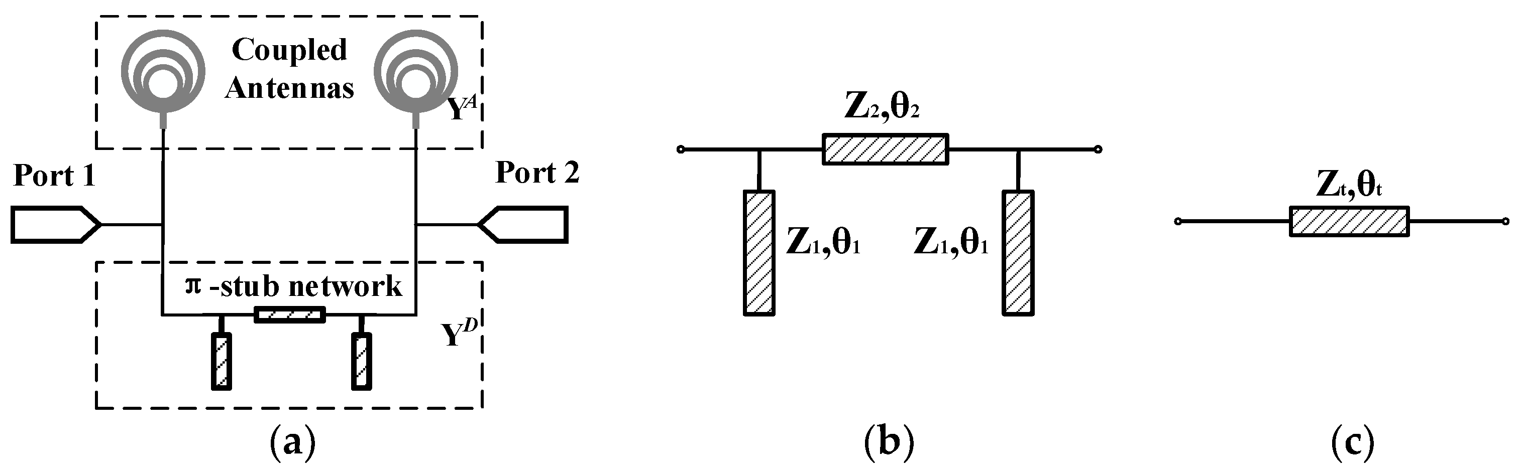
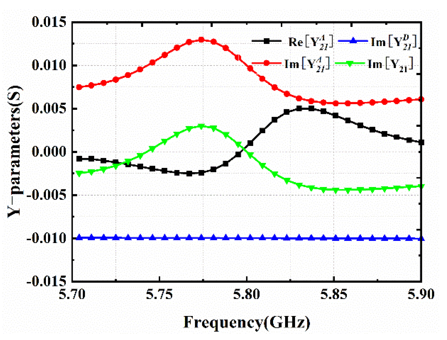
2. Design of the Decoupling Network
3. Application to RAAs
3.1. The 1 × 2 RAA
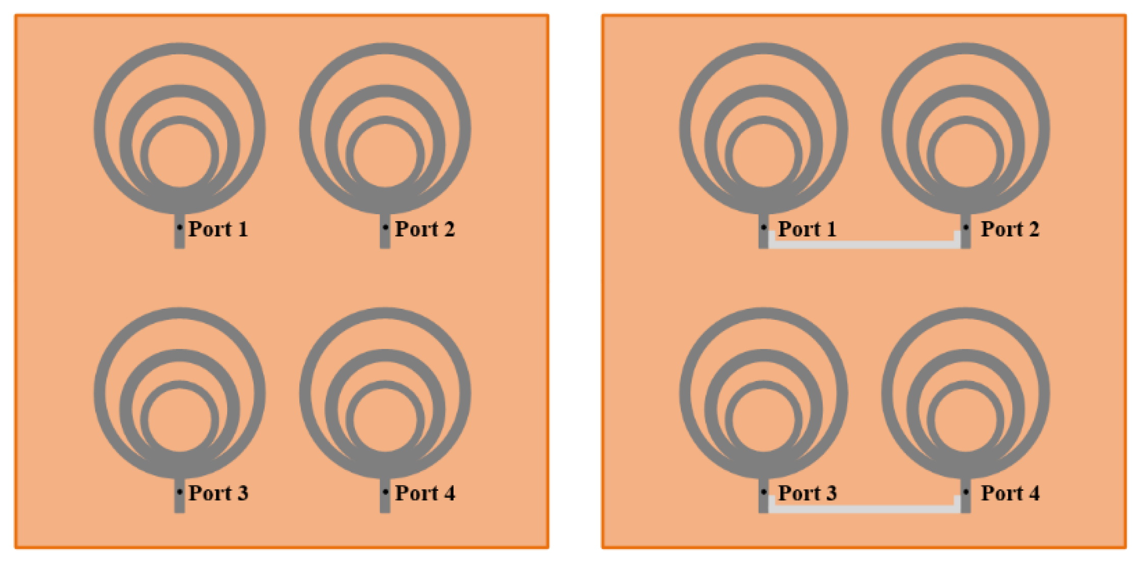
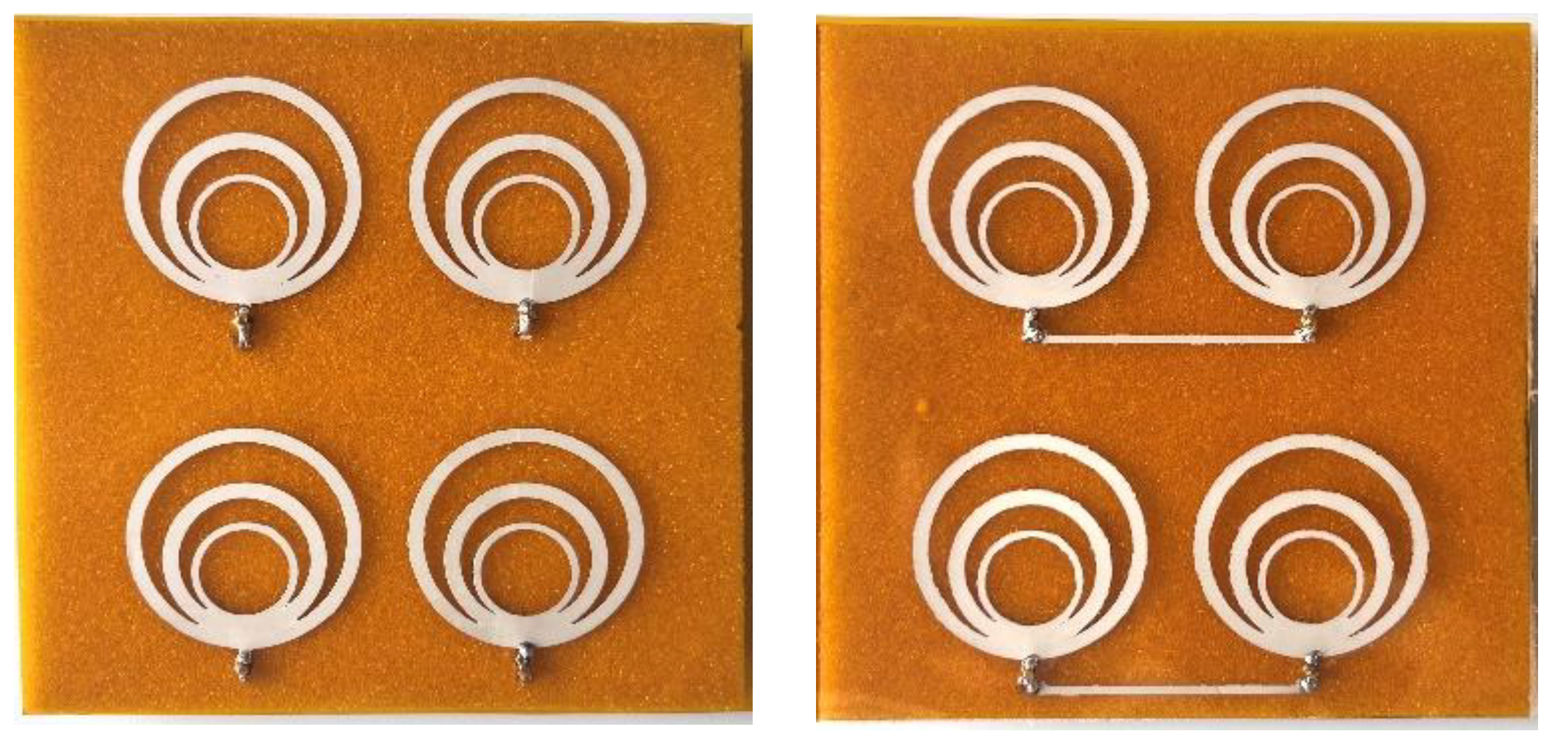
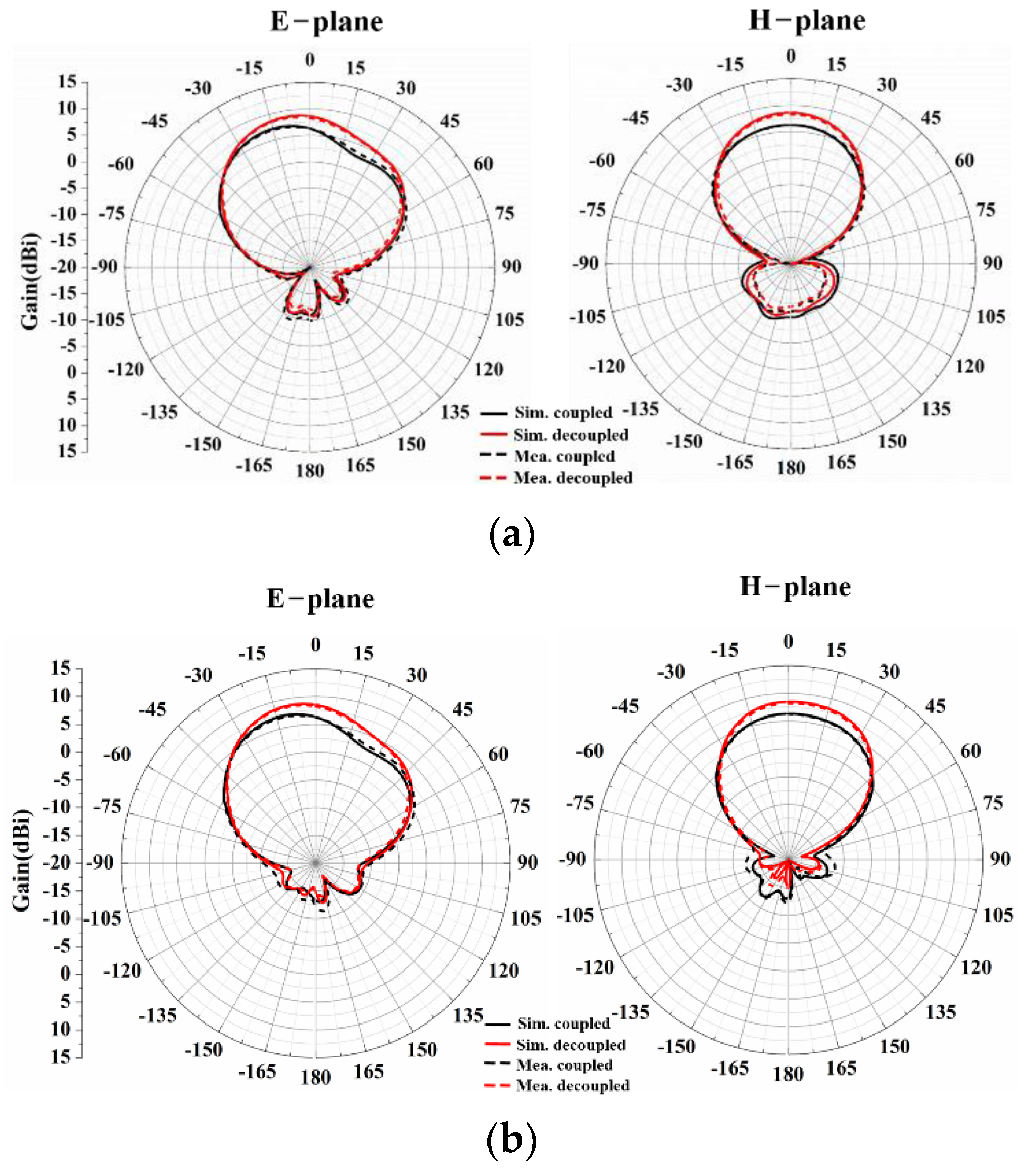
3.2. The 2 × 2 RAA
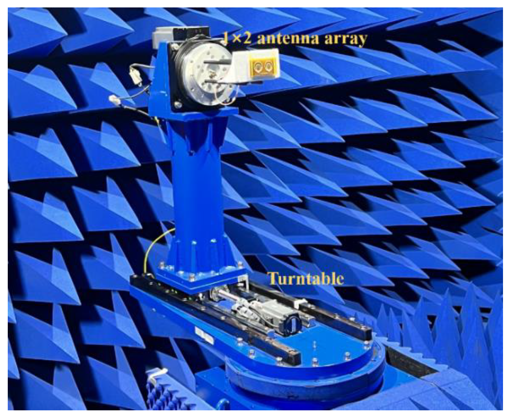
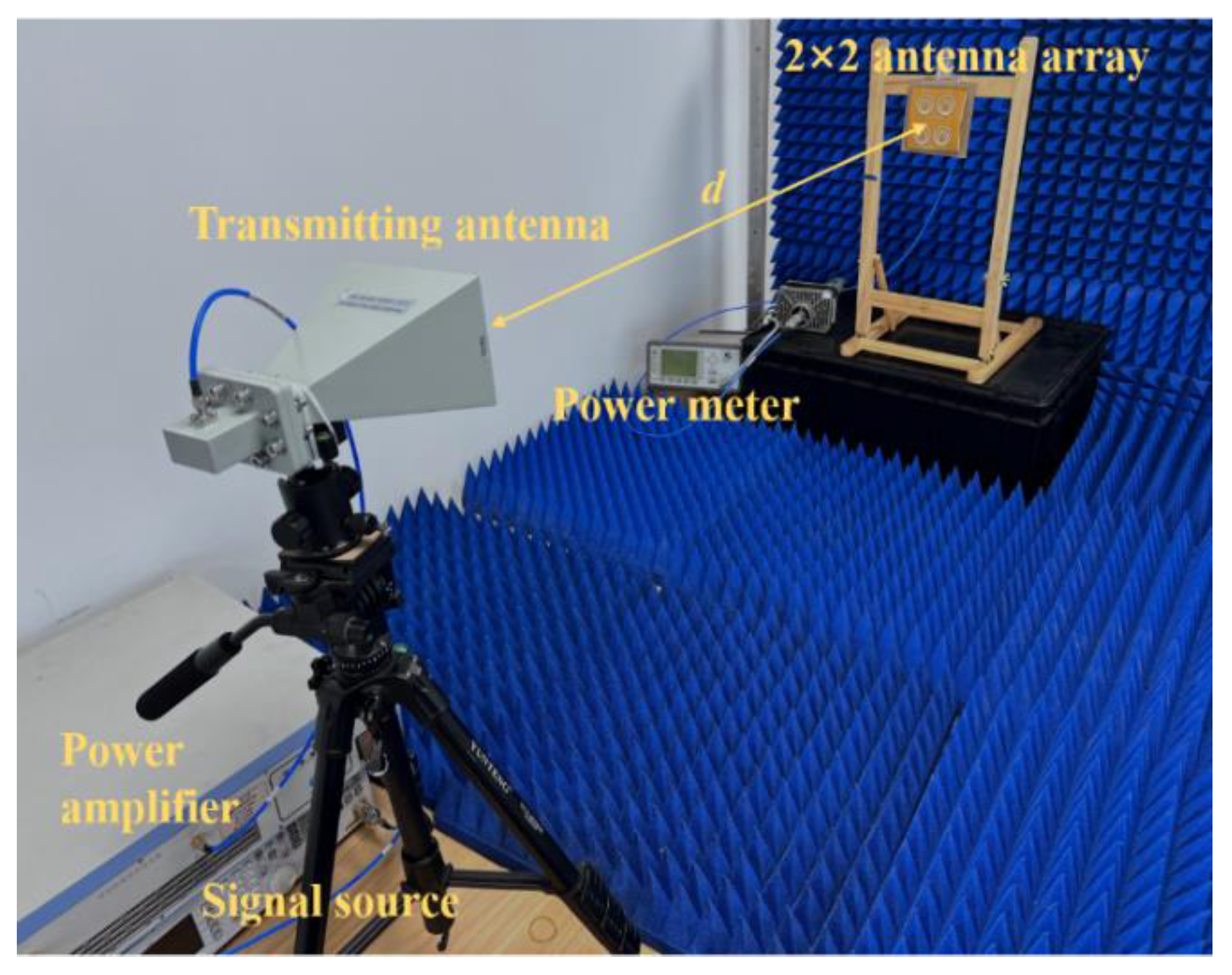
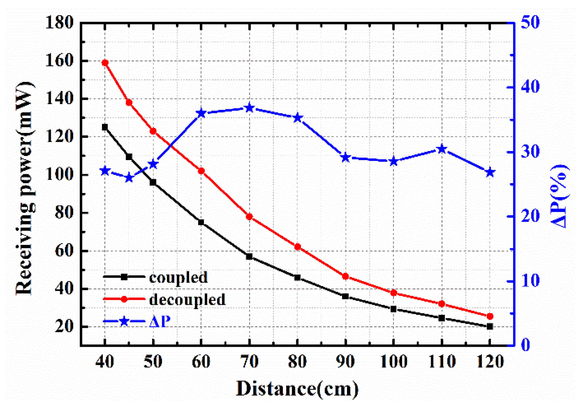
4. MWPT Experiment
5. Extended Applications
6. Conclusions
Author Contributions
Funding
Data Availability Statement
Conflicts of Interest
References
- Brown, W.C. The History of Power Transmission by Radio-Waves. IEEE Trans. Microw. Theory Tech. 1984, 32, 1230–1242. [Google Scholar] [CrossRef] [Green Version]
- Wang, H.; Deng, L.; Luo, H.; Du, J.; Zhou, D.; Huang, S. Microwave Wireless Power Transfer System Based on a Frequency Reconfigurable Microstrip Patch Antenna Array. Energies 2021, 14, 415. [Google Scholar] [CrossRef]
- Jawad, A.M.; Nordin, R.; Gharghan, S.K.; Jawad, H.M.; Ismail, M. Opportunities and Challenges for Near-Field Wireless Power Transfer: A Review. Energies 2017, 10, 1022. [Google Scholar] [CrossRef]
- Xiao, D.; Liu, S.; Fan, L.; Zhang, H.; Peng, W. Multi-target microwave energy focusing optimization method based on genetic algorithm. Aip Adv. 2021, 11, 125004. [Google Scholar] [CrossRef]
- Strassner, B., II; Chang, K. Microwave Power Transmission: Historical Milestones and System Components. Proc. IEEE 2013, 101, 1379–1396. [Google Scholar] [CrossRef]
- Zhu, X.; Jin, K.; Hui, Q.; Gong, W.; Mao, D. Long-Range Wireless Microwave Power Transmission: A Review of Recent Progress. IEEE J. Emerg. Sel. Top. Power Electron. 2021, 9, 4932–4946. [Google Scholar] [CrossRef]
- Yi, X.; Chen, Q.; Hao, S.; Chen, X. An efficient 5.8 GHz microwave wireless power transmission system. Int. J. Rf Microw. Comput. Aided Eng. 2022, 32. [Google Scholar] [CrossRef]
- Yang, F.; Rahmat-Samii, Y. Microstrip antennas integrated with electromagnetic band-gap (EBG) structures: A low mutual coupling design for array applications. IEEE Trans. Antennas Propag. 2003, 51, 2936–2946. [Google Scholar] [CrossRef] [Green Version]
- Melouki, N.; Hocini, A.; Denidni, T.A. Performance enhancement of a compact patch antenna using an optimized EBG structure. Chin. J. Phys. 2021, 69, 219–229. [Google Scholar] [CrossRef]
- Mohsen, M.K. Using EBG to Enhance Directivity, Efficiency, and Back Lobe Reduction of a Microstrip Patch Antenna. Prz. Elektrotechniczny 2021, 97, 56–59. [Google Scholar] [CrossRef]
- Chiu, C.-Y.; Cheng, C.-H.; Murch, R.D.; Rowell, C.R. Reduction of mutual coupling between closely-packed antenna elements. IEEE Trans. Antennas Propag. 2007, 55, 1732–1738. [Google Scholar] [CrossRef]
- Kumar, C.; Pasha, M.I.; Guha, D. Defected Ground Structure Integrated Microstrip Array Antenna for Improved Radiation Properties. IEEE Antennas Wirel. Propag. Lett. 2017, 16, 310–312. [Google Scholar] [CrossRef]
- Liu, R.; An, X.; Zheng, H.; Wang, M.; Gao, Z.; Li, E. Neutralization Line Decoupling Tri-Band Multiple-Input Multiple-Output Antenna Design. IEEE Access 2020, 8, 27018–27026. [Google Scholar] [CrossRef]
- Birwal, A.; Singh, S.; Kanaujia, B.K.; Kumar, S. MIMO/Diversity Antenna with Neutralization Line for WLAN Applications. Mapan J. Metrol. Soc. India 2021, 36, 763–772. [Google Scholar] [CrossRef]
- Li, M.; Jiang, L.; Yeung, K.L. A General and Systematic Method to Design Neutralization Lines for Isolation Enhancement in MIMO Antenna Arrays. IEEE Trans. Veh. Technol. 2020, 69, 6242–6253. [Google Scholar] [CrossRef]
- Guo, W.-L.; Wang, G.-M.; Ji, W.-Y.; Zheng, Y.-L.; Chen, K.; Feng, Y. Broadband Spin-Decoupled Metasurface for Dual-Circularly Polarized Reflector Antenna Design. IEEE Trans. Antennas Propag. 2020, 68, 3534–3543. [Google Scholar] [CrossRef]
- Liu, F.; Guo, J.; Zhao, L.; Huang, G.-L.; Li, Y.; Yin, Y. Dual-Band Metasurface-Based Decoupling Method for Two Closely Packed Dual-Band Antennas. IEEE Trans. Antennas Propag. 2020, 68, 552–557. [Google Scholar] [CrossRef]
- Li, M.; Jiang, L.; Yeung, K.L. A Novel Wideband Decoupling Network for Two Antennas Based on the Wilkinson Power Divider. IEEE Trans. Antennas Propag. 2020, 68, 5082–5094. [Google Scholar] [CrossRef]
- Mondal, P.; Dhara, D.; Harish, A.R. Enhancement of isolation between two closely spaced patch antennas using inter-digital capacitor and short-circuited stub-based band pass decoupling network. J. Electromagn. Waves Appl. 2022, 36, 669–681. [Google Scholar] [CrossRef]
- Zou, X.-J.; Wang, G.-M.; Wang, Y.-W.; Li, H.-P. An Efficient Decoupling Network Between Feeding Points for Multielement Linear Arrays. IEEE Trans. Antennas Propag. 2019, 67, 3101–3108. [Google Scholar] [CrossRef]
- Yi, X.; Chen, X.; Zhou, L.; Hao, S.; Zhang, B.; Duan, X. A Microwave Power Transmission Experiment Based on the Near-Field Focused Transmitter. IEEE Antennas Wirel. Propag. Lett. 2019, 18, 1105–1108. [Google Scholar] [CrossRef]
- Qian, S.; Duan, B.; Lou, S.; Ge, C.; Wang, W. Investigation of the Performance of Antenna Array for Microwave Wireless Power Transmission Considering the Thermal Effect. IEEE Antennas Wirel. Propag. Lett. 2022, 21, 590–594. [Google Scholar] [CrossRef]
- Chen, Q.; Chen, X.; Duan, X. Investigation on beam collection efficiency in microwave wireless power transmission. J. Electromagn. Waves Appl. 2018, 32, 1136–1151. [Google Scholar] [CrossRef]
- Cheng, K.K.M.; Wong, F.L. A novel approach to the design and implementation of dual-band compact planar 90 degrees branch-line coupler. IEEE Trans. Microw. Theory Tech. 2004, 52, 2458–2463. [Google Scholar] [CrossRef]
- Zhao, L.Y.; Wu, K.L. A Dual-Band Coupled Resonator Decoupling Network for Two Coupled Antennas. IEEE Trans. Antennas Propag. 2015, 63, 2843–2850. [Google Scholar] [CrossRef]
- Liu, Y.; Yang, X.; Jia, Y.T.; Guo, Y.J. A Low Correlation and Mutual Coupling MIMO Antenna. IEEE Access 2019, 7, 127384–127392. [Google Scholar] [CrossRef]
- Xia, R.-L.; Qu, S.-W.; Li, P.-F.; Yang, D.-Q.; Yang, S.; Nie, Z.-P. Wide-Angle Scanning Phased Array Using an Efficient Decoupling Network. IEEE Trans. Antennas Propag. 2015, 63, 5161–5165. [Google Scholar] [CrossRef]
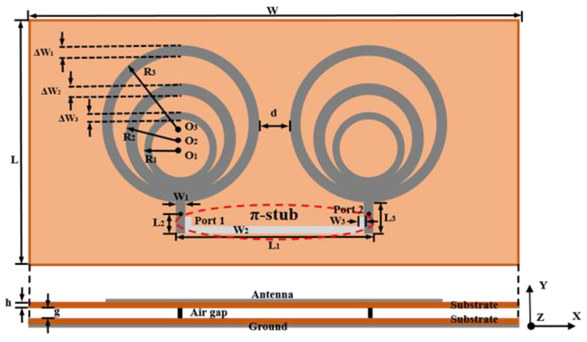


| Parameter | Unit: mm | Parameter | Unit: mm | Parameter | Unit: mm | Parameter | Unit: mm |
|---|---|---|---|---|---|---|---|
| W | 90 | ΔW1 | 1.67 | L1 | 23.06 | R2 | 10 |
| W1 | 1.4 | ΔW2 | 1.83 | L2 | 2.37 | R1 | 6.5 |
| W2 | 1 | ΔW3 | 0.83 | L3 | 4.35 | g | 1 |
| W3 | 1 | L | 45 | R3 | 14.38 | h | 0.1 |
| Reference | Decoupling Structure | Frequency | Spacing | Mutual Coupling |
|---|---|---|---|---|
| [25] | Decoupling network | 5.25 GHz | 0.17 λ | −27 dB |
| [26] | EBG | 4.95 GHz | 0.36 λ | −35 dB |
| [27] | Decoupling network | 7.5 GHz | 0.5 λ | −28 dB |
| This work | Decoupling network | 5.8 GHz | 0.39 λ | −27.4 dB |
| Parameter | Unit: mm | Parameter | Unit: mm | Parameter | Unit: mm |
|---|---|---|---|---|---|
| w | 90 | l | 90 | r3 | 14.3 |
| w1 | 2.5 | l1 | 0.93 | r2 | 10 |
| w2 | 1.2 | l2 | 3 | r1 | 6.5 |
| w3 | 1 | l3 | 36 | d | 32 |
Publisher’s Note: MDPI stays neutral with regard to jurisdictional claims in published maps and institutional affiliations. |
© 2022 by the authors. Licensee MDPI, Basel, Switzerland. This article is an open access article distributed under the terms and conditions of the Creative Commons Attribution (CC BY) license (https://creativecommons.org/licenses/by/4.0/).
Share and Cite
Li, X.; Xiao, H.; Zhang, H.; Liu, Z.; Peng, W. A 5.8 GHz π-Stub Decoupling Network for Receiving Antenna Arrays in Microwave Wireless Power Transmission. Energies 2022, 15, 8703. https://doi.org/10.3390/en15228703
Li X, Xiao H, Zhang H, Liu Z, Peng W. A 5.8 GHz π-Stub Decoupling Network for Receiving Antenna Arrays in Microwave Wireless Power Transmission. Energies. 2022; 15(22):8703. https://doi.org/10.3390/en15228703
Chicago/Turabian StyleLi, Xinyuan, Hui Xiao, Huaiqing Zhang, Zhewei Liu, and Wenxiong Peng. 2022. "A 5.8 GHz π-Stub Decoupling Network for Receiving Antenna Arrays in Microwave Wireless Power Transmission" Energies 15, no. 22: 8703. https://doi.org/10.3390/en15228703