Abstract
Different types of deep-hole blasting techniques are needed to solve gas drainage problems in complex and variable cases. Blasting parameters suitable for mines are selected based on the relationship between blast stress field changes and gas flow combined with field application and numerical simulation. The Datong Mine was a background to study the blast crush zone and drainage influence range following deep-hole blasting with holes laid in coal seams, which resulted in a 24% increase in gas flow in the drainage hole 6 m from the blast hole. In response to the difficulty of forming blast holes in the soft coal seam of the Yuyang Mine, drilling and blasting in the floor rock stratum adjacent to the coal seam increased the gas flow in the drainage holes by 125%. When applying the deep-hole technique with holes crossing multi-seams for gas drainage in Shiping Mine, the volume of gas drainage increases significantly with increased effective stress in the drainage hole. For example, when the spacing at the hole’s bottom between the blast hole and the drainage hole is 4.6 m, the volume of gas drainage increases by 3.3 times, compared with 8.8 m. Twenty-six protruding mines in southern China have applied the above deep-hole pre-splitting blasting technology, all of which have achieved good results and are of great significance to future applications in multiple fields, such as gas control.
1. Introduction
Gas explosions and outbursts are a risk in coal mining [1,2]. Gas drainage [3] benefits increase mine safety and improve mine economics [4,5]. Deep-hole pre-splitting blasting is an effective technique of gas control and outburst elimination [6], which has been applied in coal mines since the 1980s in southern China. It is used to improve gas drainage, in which the holes are laid in the coal seams. Then, it expanded to the situation that the holes crossed multi-seams and eliminated outbursts in roadways, which proved effective.
Chu et al. [7] pointed out that damage to the coal seam is mainly caused by the blasting stress wave (BSW), regardless of whether the blast holes are in the coal seam or the rocks near the coal seams. Zhu et al. [8] proposed a coupled multiphysics model for the interaction between the blasting damage of coal seams and gas flow and clarified the associated mechanisms for enhanced gas drainage induced by blasting damage. Huang et al. [9] analyzed the permeability variation under different borehole intervals and sealing lengths. It improved the average extraction concentration and pure volume of the extraction borehole in the field tests. Chen et al. [10] enhanced coal seam permeability using deep-hole pre-splitting blasting. The drainage gas purity and flow rate increased significantly. Xie et al. [11] optimized the arrangements of the drainage and blasting holes according to the variations in specific distance stress and longitudinal-wave velocity around the blast site. Yue et al. [12] optimized the layout of the blast holes and drainage holes by considering the anisotropy mechanical property and enhanced the methane concentration and gas drainage quantity underground in situ measurement. Ti et al. [13] calculated the extraction radius of the drilling hole based on the mechanical model for deep-hole pre-splitting blasting crack expansion, improved the permeability of the coal seam gas drainage, increased the quantity and rate of extraction, and reduced methane output. Wang et al. [14] used the synergistic antireflection technology of hydraulic fracturing and deep-hole pre-splitting blasting. It has a significant antireflection effect in low-permeability coal seams. Li et al. [15] put forward a co-penetration technology of hydraulic punching and deep-hole pre-splitting blasting, which increased the average and maximum purity of the gas extraction and improved the permeability of the coal body. Jia et al. [16] developed a multi-field coupling physical simulation experimental device to study the influence of the increase in boreholes on the gas drainage effect. Other scholars [17,18] used experimental studies and numerical simulations to investigate how deep-hole pre-splitting blasting can improve gas drainage. However, the above studies have discussed the characteristics of deep-hole blasting technology from various aspects of theory and application, and more papers have focused on blasting processes and specific technologies.
The problem is that many mines in southern China have complex gas occurrences [19,20]. In some cases, deep-hole blasting can improve the gas drainage rate, but in many cases, it is difficult and impossible to blast due to the soft coal seam. There are few studies on adopting various methods to expand the application of deep-hole blasting and determine the blasting parameters in theory.
The authors have applied deep-hole pre-splitting blasting technology to improve gas drainage rates in 26 coal mines in southern China, using various blasting techniques for different situations and achieving good results. This paper discussed three typical deep-hole blasting techniques based on these. Namely, the deep holes lay in coal seams, crossing coal and rock seams, and in the adjacent rock stratum. Their respective blasting mechanisms and main parameter determination methods are found by field application combined with numerical simulation, which is of reference and guiding significance for more extensive use of deep-hole blasting for gas control in the future.
2. Problems and Solutions When Applying Deep-Hole Blasting in Gas Drainage
2.1. Problems with Deep Hole Lie in Different Coal and Rock Media
There are three typical applications of deep-hole pre-splitting blasting due to differences in the conditions of the blasted coal and rock bodies.
Deep-hole pre-splitting blasting has a good effect on improving gas drainage from low-permeability coal seams. Deep holes can be placed directly in the coal seam without collapse when the coal seam is hard enough. After blasting, the coal body near the blast source is deformed and destroyed, and extended connected fissures are formed in the middle and far areas, allowing early discharge of gas in the coal seam and reducing the risk of outbursts. In this case, the technical focus is to explore the selection of optimal hole-position parameters according to the blasting mechanism in the coal seam.
Deep-hole pre-splitting blasting can also achieve better results in uncovering coal in crosscuts, outburst elimination of local areas, and so on in specific locations. After passing through the rock stratum, the blast hole will enter the coal seam. In complex cases, there are multiple alternations of coal and rock media along the whole length of the blast hole. In this case, the blasting stress distribution is complicated since the difference between the coal and rock media, the variable number of layers, and alternation occurs at different locations, while the blast holes and drainage holes are mostly fan-shaped, and the burdens vary along the holes. Thus, the design needs to consider safety at the hole’s entrance and a good effect in blasting at the hole’s bottom.
When it is hard to form blast holes in loose and soft coal, if deep-hole pre-splitting blasting technology is still to be applied, the blast holes can be laid in the rock adjacent to the coal seam, and the drainage holes are still in the coal seam. After blasting, it can achieve good results through the simultaneous drainage of gas in the holes in the rock and coal seams. The dissipation of the blast stress wave as it traverses the interface makes it significantly different from deep-hole blasting in the coal seam. In this case, the technical difficulty lies in determining a reasonable hole-layout scheme to maintain a blasting effect comparable to that of blasting in the coal seam.
2.2. Solutions to Deep-Hole Pre-Splitting Blasting in Different Cases
- (1)
- Blast holes laid in the coal seam
We collected the coal parameters in the field. Numerical simulation was used to examine the crush zone, stress action range, and displacement field to determine the proper hole spacing. The effect of deep-hole blasting to promote gas drainage was verified by on-site gas flow monitoring.
- (2)
- Blast holes crossing multiple seams of coal and rock
We collected the coal and rock parameters in the field. The hole spacing at the entrance and bottom and the hole angle were coordinated by analyzing the magnitude of effective stress and comparing the measured gas drainage from different control holes.
- (3)
- Blast holes laid in the rock stratum
We collected the coal and rock parameters in the field. Rock blasting transfers its action to the coal and is reduced compared to blasting in the coal seam. Therefore, multiple models are built, the difference being the spacing between the blast hole and the drainage hole. The stress distribution along the axis of the control holes is analyzed to find the hole spacing equivalent to blasting in the coal seam. Actual gas flow measurements verified the simulation results.
2.3. Theory of the Numerical Calculation for Deep-Hole Blasting
Numerical simulation is used to study deep-hole pre-splitting blasting.
According to the characteristics of coal and rock, the material constitutive model adopts *MAT_PLASTIC_ KINEMATIC, which is suitable to simulate the isotropic and kinematic hardening plasticity. The dynamic yield stress σy is calculated according to the Cowper–Symonds model as shown in Equation (1).
where σ0 is the initial yield strength. C and p are material constants. β is an adjustable parameter. β = 0 for the kinematic hardening model. β = 1 for the isotropic hardening model. έ is the strain rate. Ep is the plastic strengthening modulus. is the effective plastic strain.
The Jones-Wilkins-Lee equation of state (JWL EOS) gives the detonation pressure P, as shown in Equation (2).
where V is the relative volume. E0 is specific internal energy. A, B, R1, R2, and ω are five constants related to material properties.
The mechanical parameters of coal and rock, such as density (ρ), Young’s modulus (D), Poisson’s ratio (μ), compressive strength (σs), etc., need to be obtained by actual measurements in different mines. Table 1 shows the explosive parameters, which are calculated by the γ-fitting method, and the explosive density, detonation velocity, and constant E0 are obtained from the measured results. E0 is proportional to the detonation heat.

Table 1.
Explosive parameters.
3. Deep-Hole Pre-Splitting Blasting with Holes Laid in Coal Seams
3.1. Engineering Background and Blast Hole Design
Deep-hole blasting in a coal seam is to blast coal before gas drainage to increase the drainage rate. Control holes lay adjacent to the blast holes to increase the space for crushing and swelling. They are also gas drainage holes after detonation. Table 2 shows the measured coal parameters in a deep-hole blasting test carried out at the S1721 working face of Datong No. 1 Mine. The paper analyzed the crushing zone formed after the blasting- and the gas drainage-affected area by stress waves. Besides, it discussed the stress changes near the blast hole and the control hole with different spacing.

Table 2.
Mechanics parameters of coal in Datong No. 1 Mine.
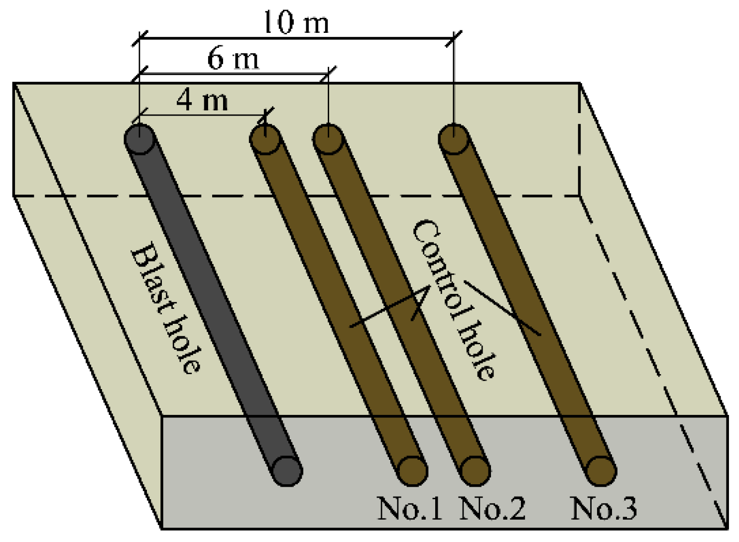
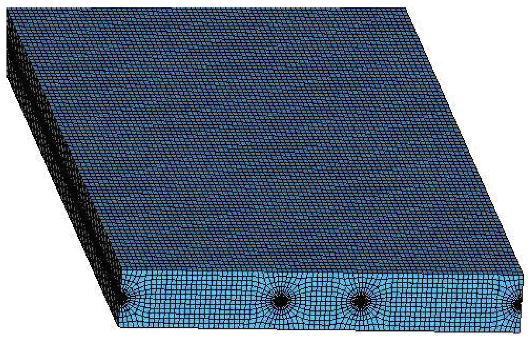
One blast hole and three control holes are arranged as shown in Figure 1. The spacing from the blast hole to each control hole is 4 m, 6 m, and 10 m. The diameter of the blast hole is 90 mm, the charge length of the explosive is 40 m, the stemming is 1 m, and the control hole is 42 m. The model is 10 m wide, 1.5 m thick, and 42 m long, as shown in Figure 2. According to the test on-site, the working face is simplified to a continuous media model, and the type of model unit is Solid164. The other two sides and bottom surfaces applied non-reflective boundary conditions. Both symmetric surfaces of the model applied the normal displacement constraints. The model is simplified by taking the upper part of the whole model according to symmetry to be easy to compute. The simplified model size is 10 m × 75 cm × 42 m.
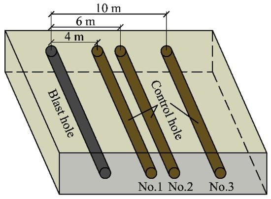
Figure 1.
Hole layout.
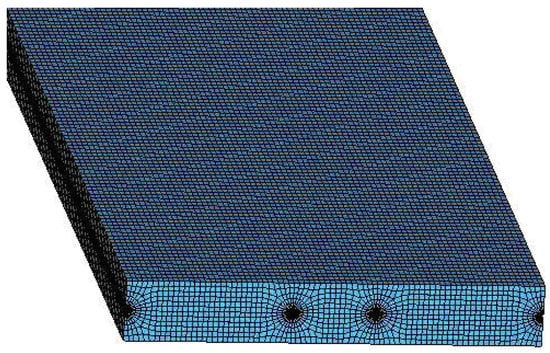
Figure 2.
Computation model (partial).
3.2. Results and Analysis of Numerical Calculation
3.2.1. Range of Crushing Failure along Each Point of the Blast Hole Using Hole-Entrance Initiation
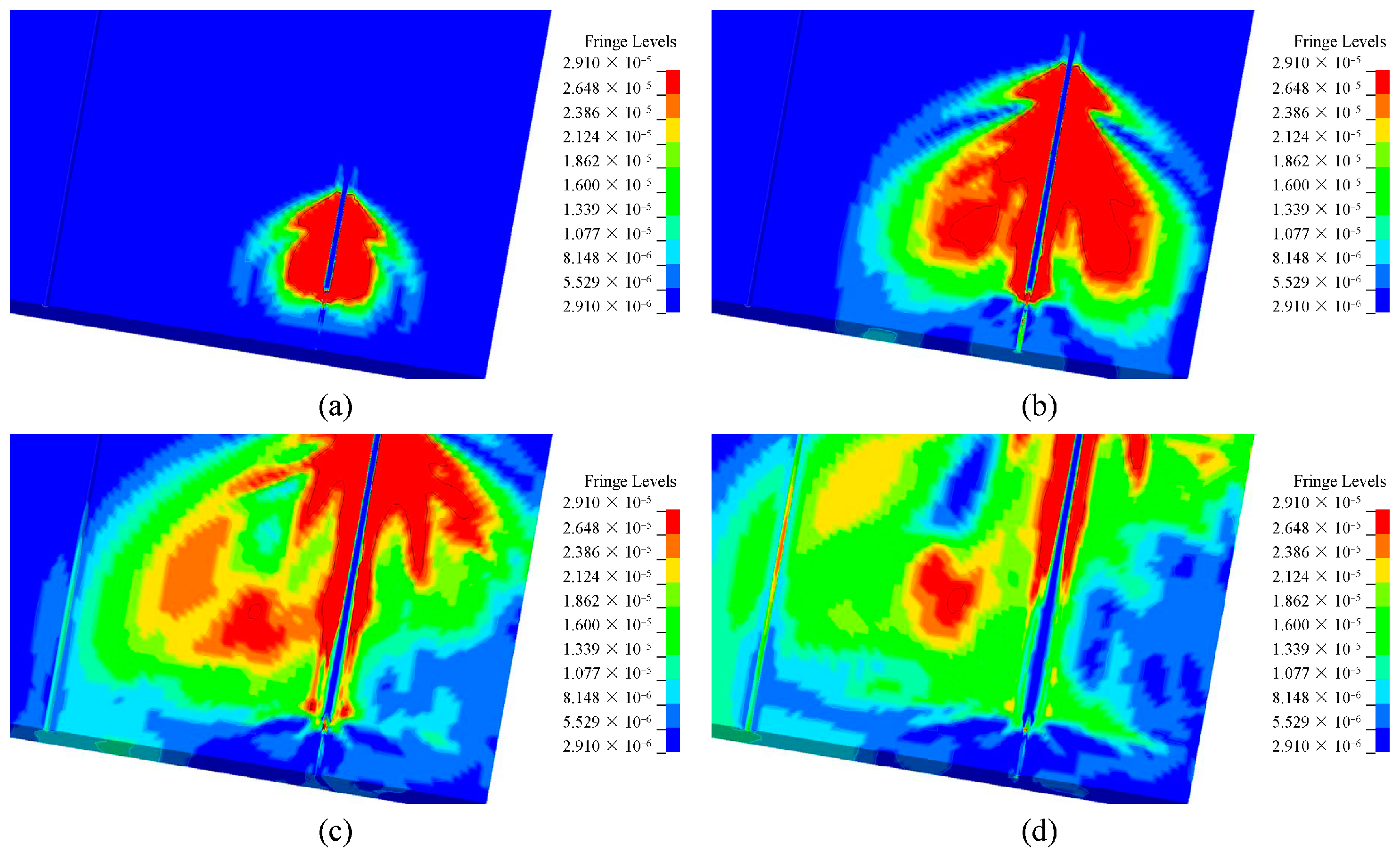
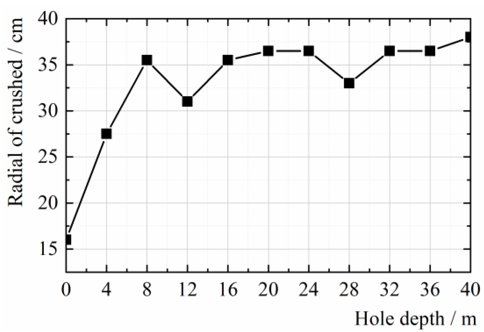
The stress on the coal exceeds a certain value of its yield strength to destroy it. Figure 3 shows the radial failure of the local element along the blast hole at different times. The failure range does not change at 8800 μs after initiation. The final crushing failure range at each location along the hole axis is given in Figure 4. The origin means the initiation point. As shown in Figure 4, the crushing failure range at each point along the blast hole increases sharply from the origin to 8 m. It increases slowly from 8 m to 40 m. The radius of the failure range is approximately equal to 35 cm. It indicates that the failure range at the middle and bottom of the blast hole is larger than that at the hole entrance.
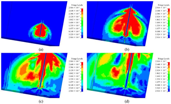
Figure 3.
Part zoom-in pictures of dead elements around the blasting hole: (a) 400 μs; (b) 1600 μs; (c) 3000 μs; (d) 3700 μs.
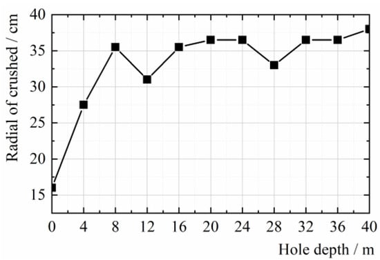
Figure 4.
Final radial crushing failure range crushed at each point along the blast hole.
3.2.2. Displacement Field Analysis of Control Holes at Different Spacing from the Blast Hole
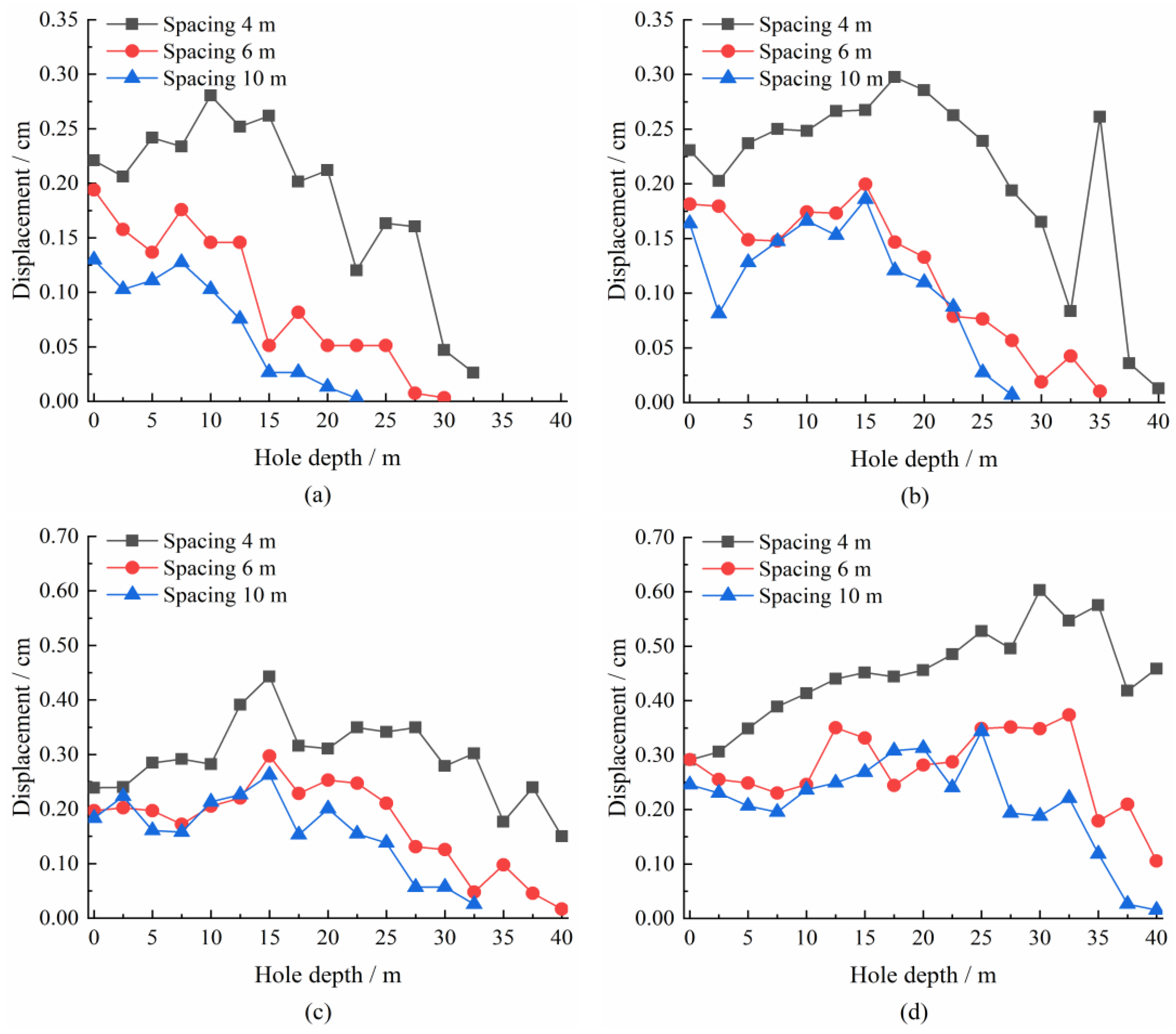
The effective displacement of each control hole at different moments after blasting is shown in Figure 5. The spacing from the blast hole to each control hole is 4 m, 6 m, and 10 m. The stress wave propagates to the bottom of the blast hole at 6000μs. Thus, Figure 5 lists displacements at critical moments from 6000 μs to 9000 μs.
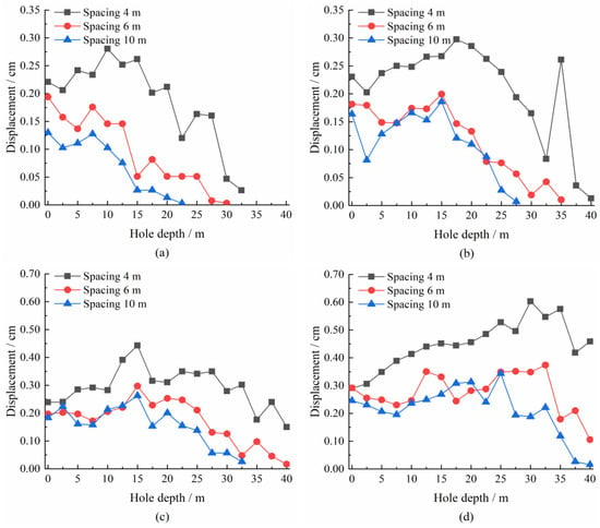
Figure 5.
Displacement comparison along the control holes at critical moments after initiation: (a) 6000 μs; (b) 7000 μs; (c) 8000 μs; (d) 9000 μs.
The coal seam is softer than the rock. Thus, the coal media has a strong energy absorption effect on the stress wave. It can show in the variation of the displacement field. The maximum displacement of control hole No. 1 is 0.54 cm, which appears at 32.5 m from the initiation point. The effective displacement of the other control holes is much smaller than that at the same time and position. It indicates that control hole No. 1 is subject to greater action. With time increasing, the maximum effective displacement of each control hole moves gradually from the hole’s entrance to the bottom. The maximum value is close to the hole bottom at 9000 μs.
3.3. Field Application and Summary
Field application validated the result of numerical simulation.
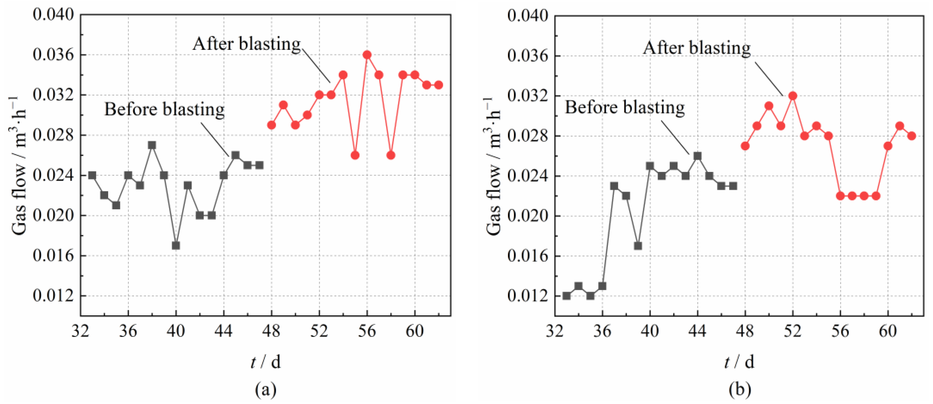
The initiation of the blast hole significantly affects control hole No. 1 in a large area. It can be seen from the gas flow detected after deep-hole pre-splitting blasting at the S1721 working face. The volume of gas drainage has a significant improvement of nearly two times on the second day. As seen from the long-time drainage, the most visible effect happened to control hole No. 1, and the effective radius of gas drainage reached 10 m. The average gas flow of control holes No. 2 and No. 3 within 15 days after the blasting is 24% and 20% higher than before, while the drainage volume of control hole No. 3 is slightly improved compared with that of hole No. 2. Figure 6 shows the result. The feature is consistent with the change of effective displacement. Thus, the effect is immediately apparent after blasting, but the control hole is prone to collapsing and impairing gas drainage over time. It is better to arrange the control hole 4 m from the blast hole.
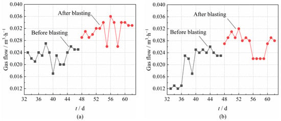
Figure 6.
Gas flow change of control holes in S1721 working face of Datong No. 1 Mine: (a) control hole No. 2; (b) control hole No. 3.
As seen from these experiences, since blasting in a coal seam contacts the coal body over a large area, it is simple and has the best drainage effect among all deep-hole blasting techniques, but the premise is that the coal seam is hard enough.
4. Deep-Hole Pre-Splitting Blasting with Holes Crossing Seams
Deep-hole cross multiple seams are widely used in gas drainage when uncovering coal in crosscuts, gas drainage crossing multiple seams, outburst elimination in local areas, and so on. Because of the small contact surface between the blast hole and the coal seams, it is hard to position the charge in the blast hole. It requires a high level of blasting technology. Using Shiping Mine as the research background, a model containing the coal-rock media helps study the relationship between the propagation characteristics of the blasting stress field and the effect of gas drainage. It obtained the critical hole spacing to keep the blasting effects through the test.
4.1. Engineering Background and Blast Hole Design
We carried out deep-hole pre-splitting blasting at +700 m C15 floor drift in Shiping No. 1 Mine. There are 2~3 coal seams at cross-cut No. 2. The coal seams are approximately perpendicular to the drift and change to parallel to it with a twist of about 90°, which causes a sharp increase in gas pressure. When drilling cross multi-seams, it would result in gas blow-out from the hole or resist the drill. Therefore, it needs to eliminate the outbursts by blasting.
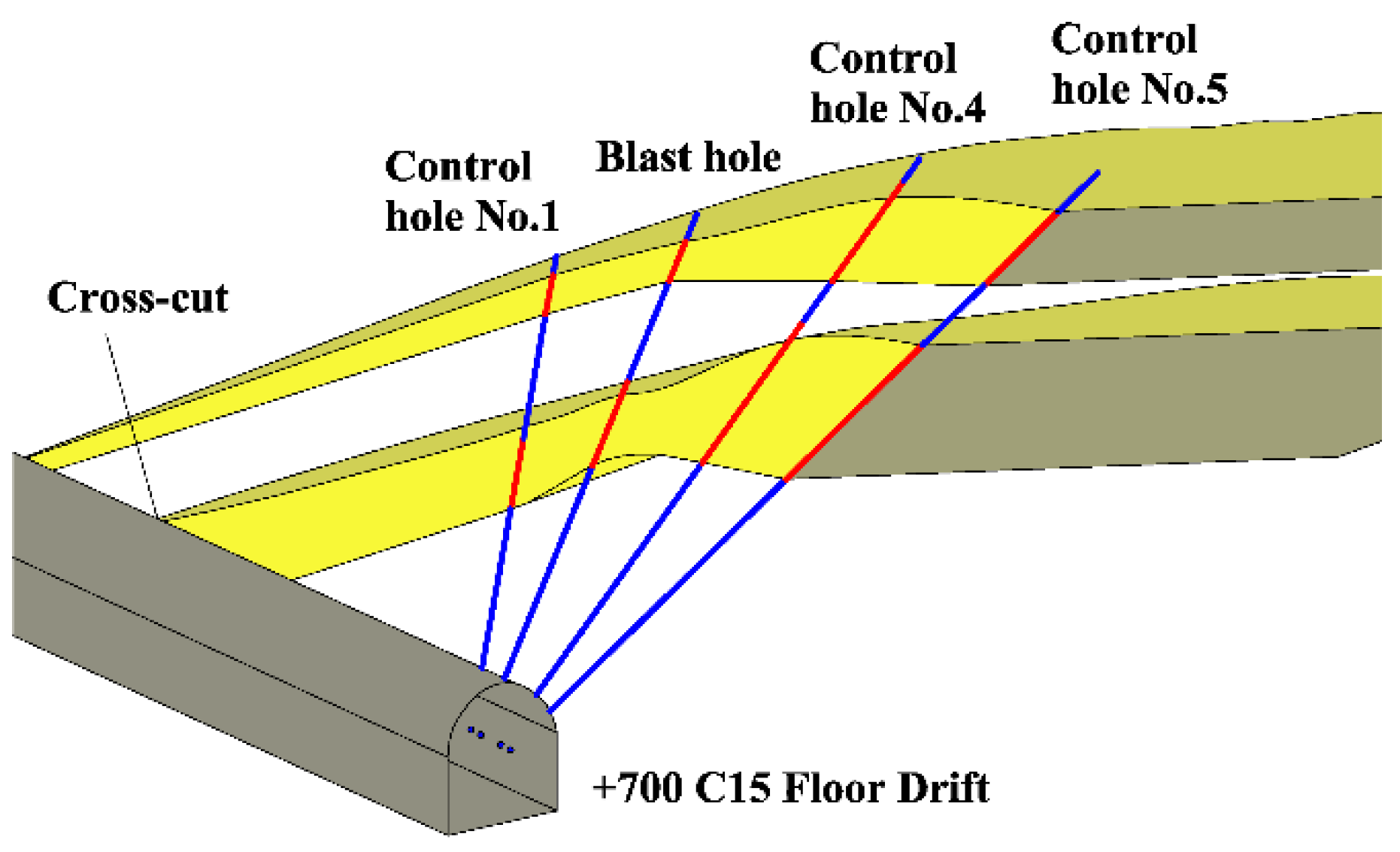
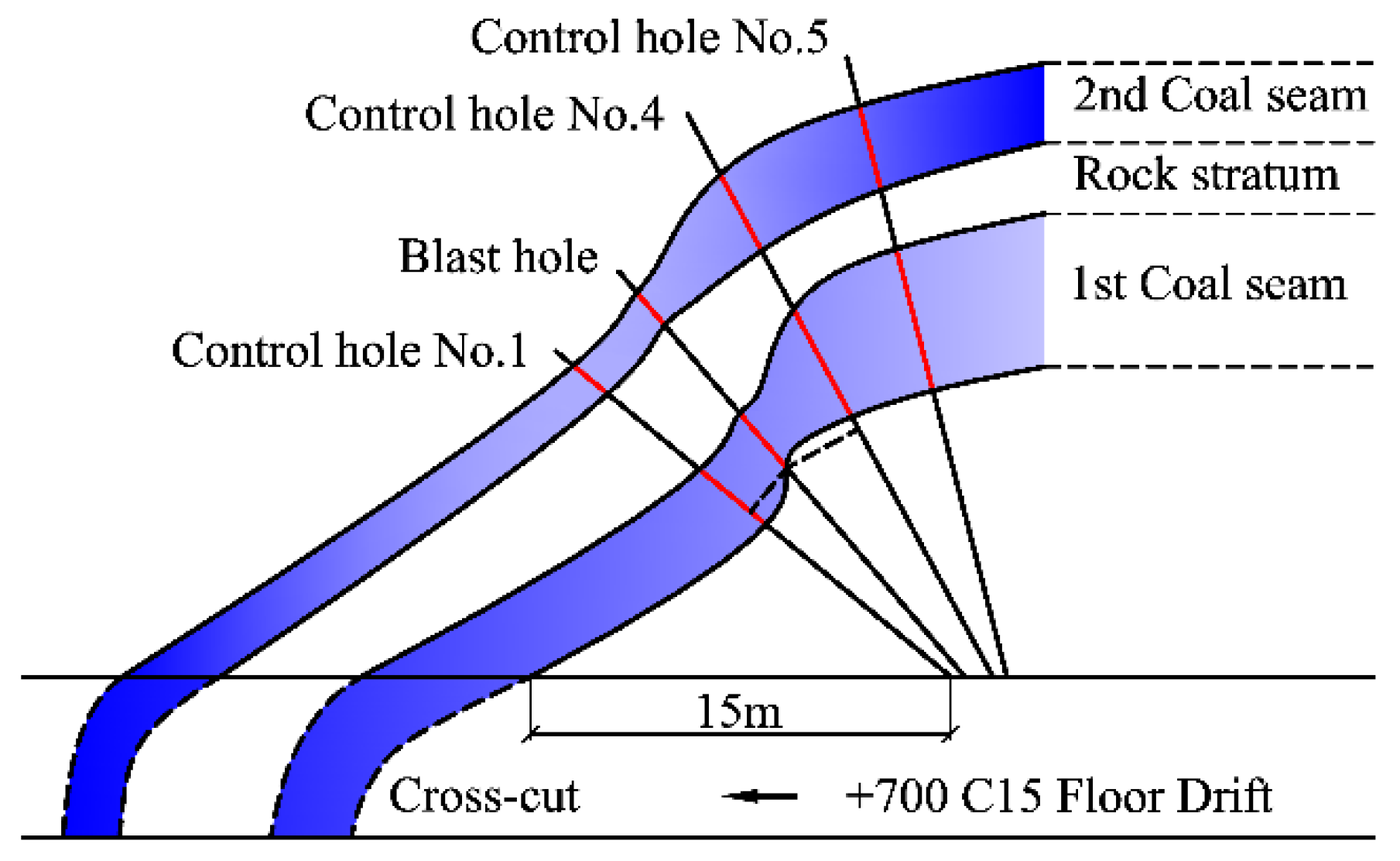
On-site measurement shows that the blast hole traverses the rock stratum, coal seam, rock stratum, and coal seam in that order. The hole length in each seam is 10, 3, 3, and 1.5 m. Blast and control holes Nos. 1, 4, and 5 are coplanar and arranged in a fan design. Their respective angles with the blast hole are 10°, 13°, and 16°. These holes are designed to compare the stress variations caused by different hole spacing. The burden at the entrance of the three control holes is 1.90 m, 2.92 m, and 5.41 m, and that at the bottom of the three ones is 3.22 m, 4.64 m, and 8.77 m. Figure 7 and Figure 8 show the hole layout. It uses the hole-entrance initiation.
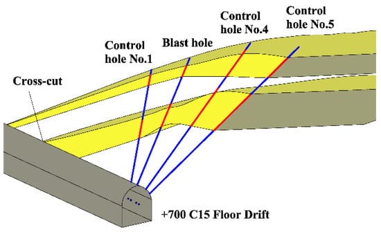
Figure 7.
Three-dimensional view of the hole layout.
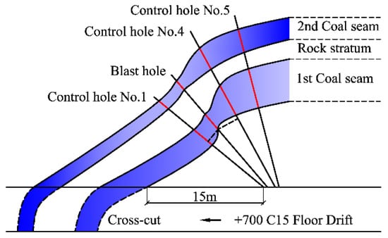
Figure 8.
Positional relations of four holes.
4.2. Modeling
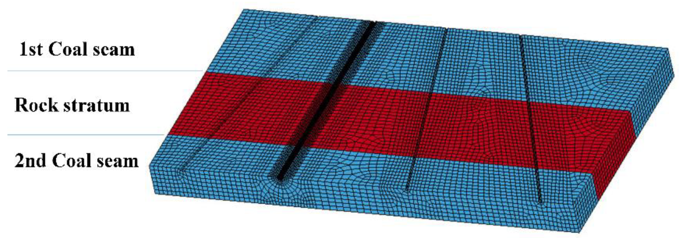
Figure 9 shows the model built according to the actual hole-layout design. The part near the entrance of the blast hole, namely in the first rock stratum, is 10 m long and stemmed, so the model does not contain this rock stratum. The blast holes in the model start at the interface between the stemming and charging, end at the interface between the second coal seam and the third rock stratum, and pass through the first coal seam, the second rock stratum, and the second coal seam in that order. The minimum distance from the boundary on both sides of the model to control holes No. 1 and No. 5 is 1 m. The model is 13.48 m long, 7.5 m wide, and 1 m high. Table 3 shows the mechanical parameters of coal and rock.
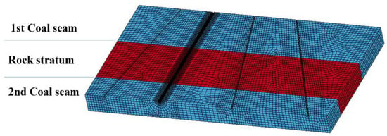
Figure 9.
Model of hole crossing seams.

Table 3.
Mechanics parameters of coal and rock in Shiping No. 1 Mine.
4.3. Results Analysis
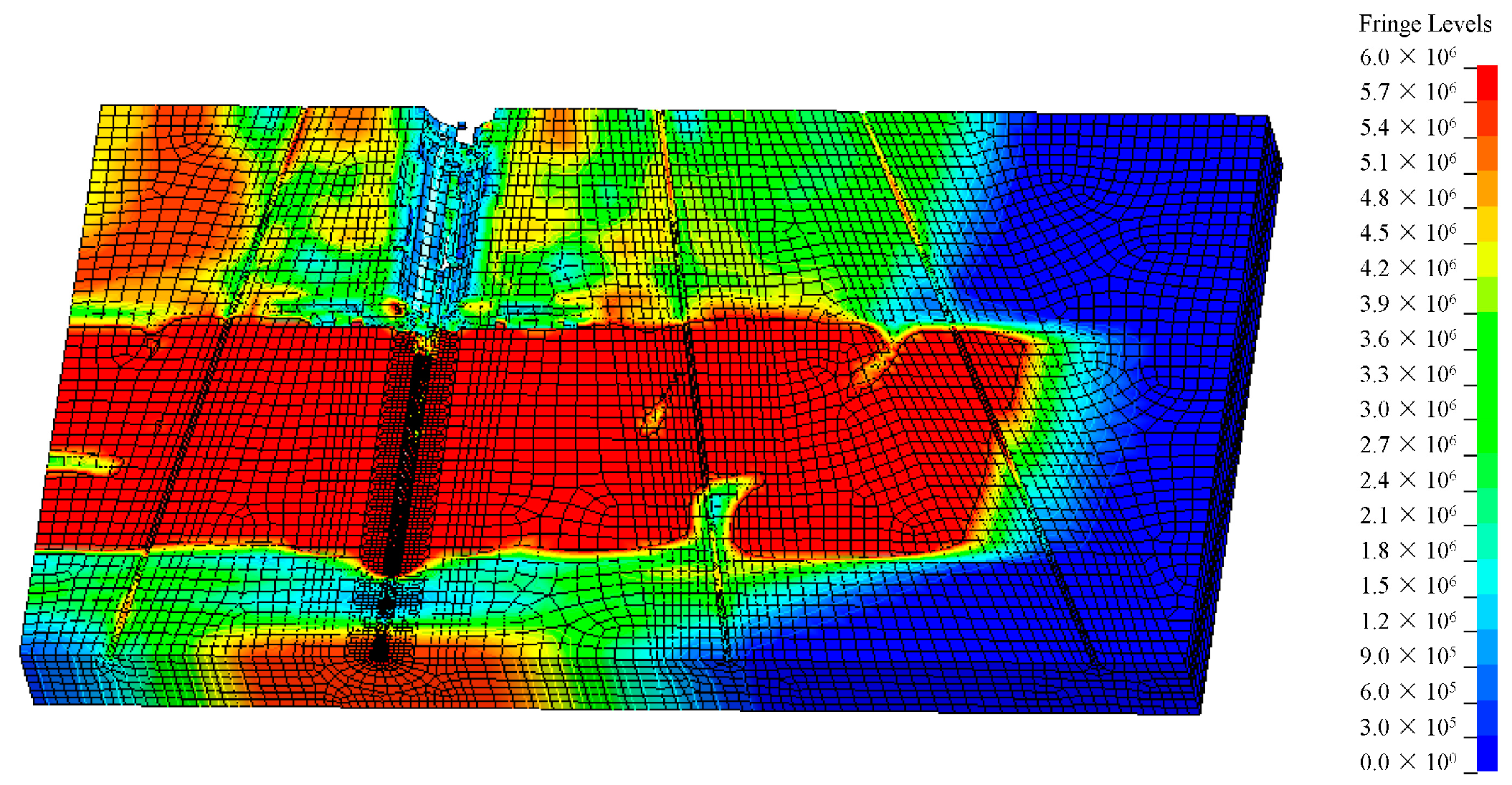
Figure 10 shows the 3D cloud map of effective stress at 2 ms after initiation. Since the gas drainage hole (control hole) crosses multiple rock and coal seams, the rock stratum and the interface reflection all influence the stresses on each coal seam. It cannot be analyzed along the whole length of the hole but needs to be explored separately for the two coal seams that the hole crosses.
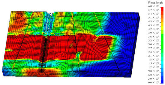
Figure 10.
Three-dimensional cloud of effective stress (t = 2.0 ms).
4.3.1. Effective Stress Comparison along the Axis of Control Holes which Cross Two Coal Seams in a Fan Layout Pattern
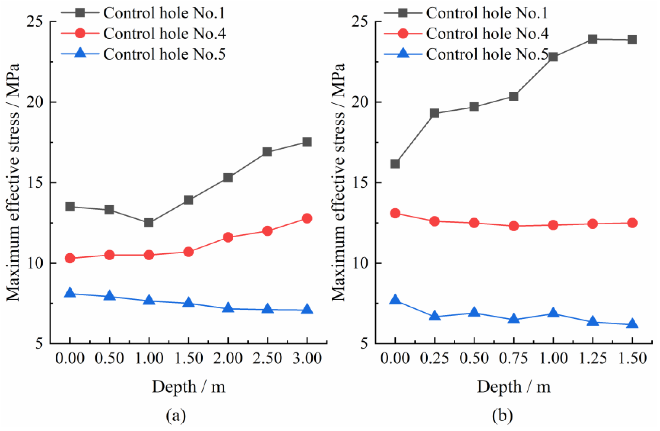
Each of the seven observation points lay in two coal seams along the axis of the control hole. Figure 11 illustrates the variation of the maximum effective stress.
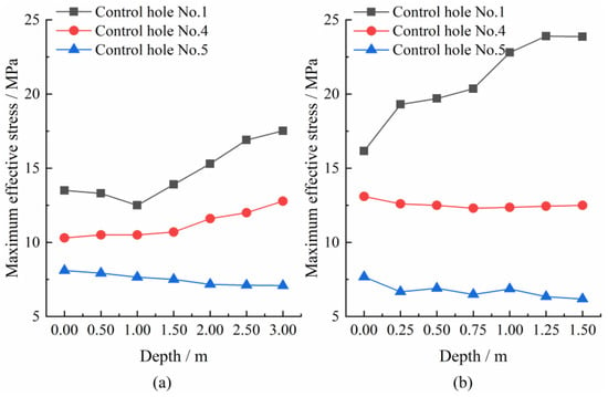
Figure 11.
Comparison of variation of the maximum effective stress with position along hole axis: (a) first coal seam; (b) second coal seam.
The origins in Figure 11a,b refer to the points of the control hole entering the first and the second coal seam. As shown in Figure 11a, the maximum effective stress increases as control holes No. 1 and 4 are deep into the first coal seam, while that decreases for control hole No. 5 because it is farthest from the blast hole. As shown in Figure 11b, with the distance from the origin increasing, the maximum effective stress of control hole No. 1 increases while No. 4 and No. 5 decrease. Therefore, the stress variation trend along the hole axis varies in the two coal seams. It is more complex than blasting in a single seam.
Comparing the average stresses in two coal seams, the values for control holes Nos. 1 and 4 are 20.87 and 12.54 MPa in the second seam while 14.7 and 11.20 MPa in the first seam. The effective stress and its mean value of control hole No. 5 in two coal seams range from 6.7 to 7.5 MPa. It means that the closer the spacing between the blast hole and the control hole, the higher the difference in the effective stress.
4.3.2. Relationship between Effective Stress and the Volume of Gas Drainage
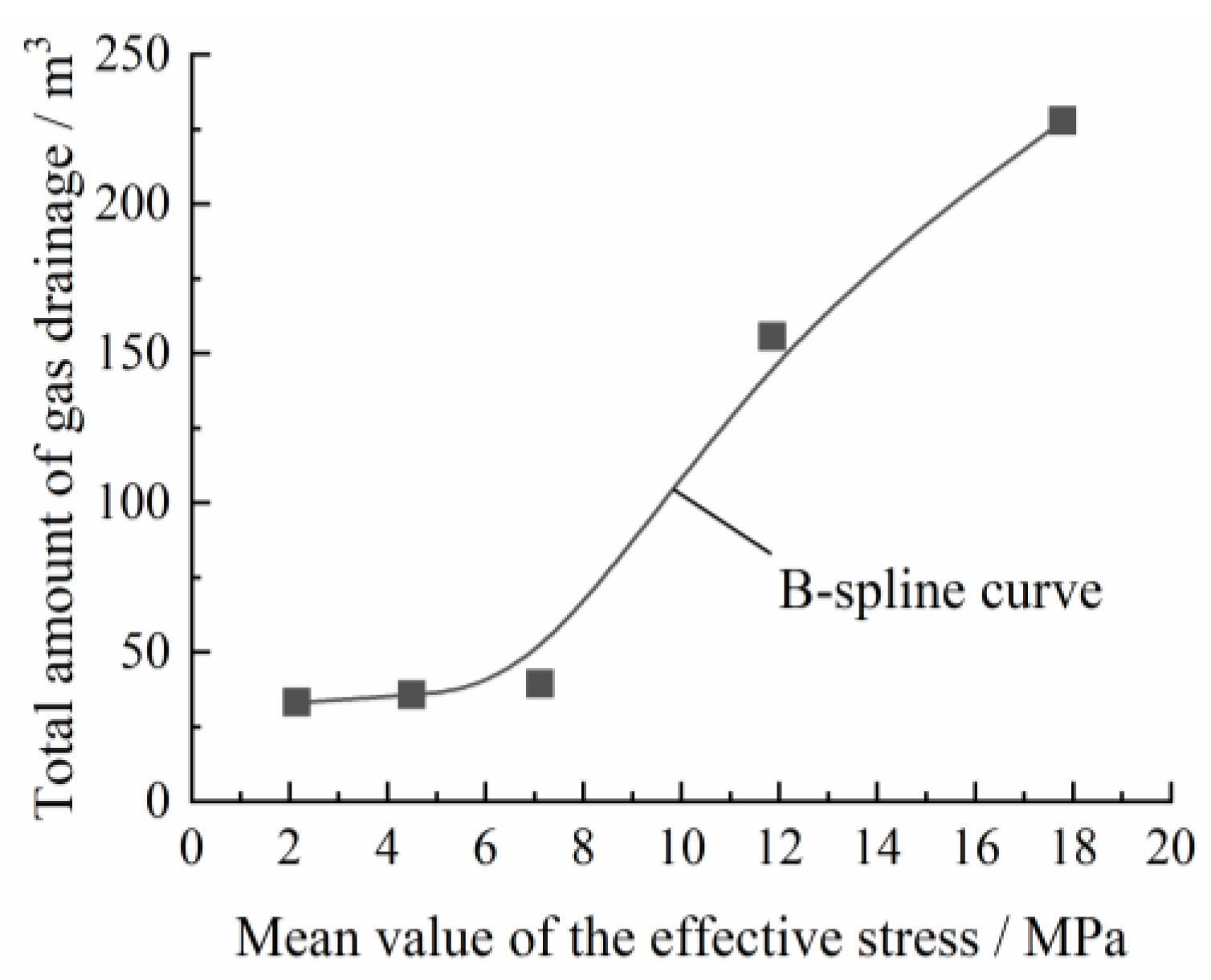
The total volume of gas drainage per hole is monitored underground for 22 days. The rise in volume verifies the effectiveness of blasting, which is thanks to an increase in effective stress.
Figure 12 shows the relationship between the total volume of gas drainage and the mean value of the effective stress, which refers to the mean value of the same drainage hole in two coal seams. The gas drainage increases more than three times when the mean value of the effective stress is more than 12 MPa. The total volume of gas drainage is less than 39 m3, with little change when the average effective stress on the coal seam is less than 7.12 MPa.
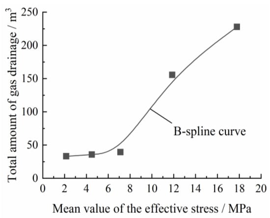
Figure 12.
Volume of gas drainage changes with average effective stress.
4.3.3. Volume Comparison of Gas Drainage for Each Control Hole after Blasting
Field application results show that spacing is related to gas flow.
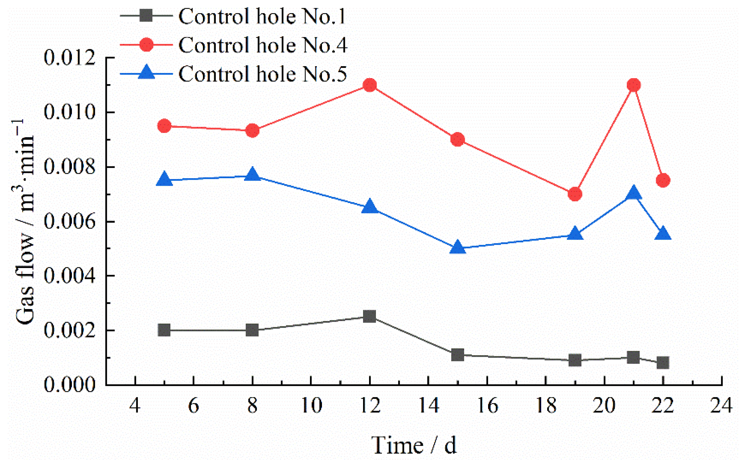
The gas flow of control holes Nos. 1, 4, and 5 are detected after blasting to compare the gas drainage effect of different control holes. Control hole No. 1 is the closest to the blast hole. As shown in Figure 13, the average gas flow of control holes Nos. 1 and 4 is 502% and 331% that of control hole No. 5. Thus, blasting has a much higher effect on the gas drainage rate of control holes No. 1, 4 than No. 5. Hole No. 4 is the critical position to ensure the blasting effect. The effect is remarkable after blasting when the angle between the control hole and the blast hole is 13°, while the spacing at the hole entrances and the hole bottoms is not more than 2.9 m and 4.6 m.
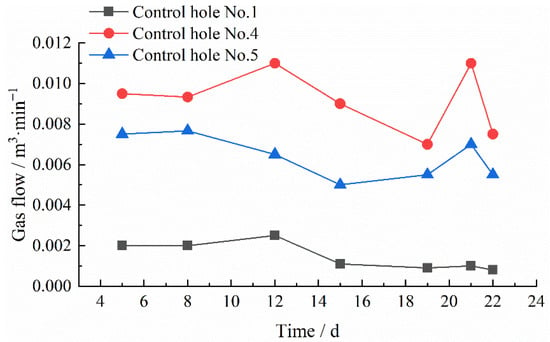
Figure 13.
Volume comparison of gas drainage for each control hole after blasting.
4.4. Summary
Deep-hole blasting cross seams use hole-entrance initiation in the coal-rock media. The damage is better at the hole bottom than at the hole entrance. The effective stress on the hole-bottom side is 73% larger than the hole-entrance side. The volume of gas drainage can increase more than three times when the mean value of the effective stress is more than 12 MPa. The spacing between the control and blast hole affects the effective stress significantly.
5. Deep-Hole Blasting with Holes in the Floor Rock Stratum Adjacent to the Soft Coal Seam
In southern China, the soft coal seams make it difficult to shape the holes and impossible to perform blasting. Therefore, the blast holes can lay in the floor rock stratum adjacent to the coal seam, which avoids the hole collapse and solves implementation barriers of deep-hole blasting. Taking Yuyang Mine as the background, we explored the differences between blast holes lying in coal and rock. Then, we established models in two types for coal-rock and coal-only media, analyzed the dynamic stresses propagated to the coal seam by rock blasting under different hole-layout parameters, and obtained the optimal hole-layout scheme.
5.1. Characteristics of Deep-Hole Blasting in the Floor Rock Stratum
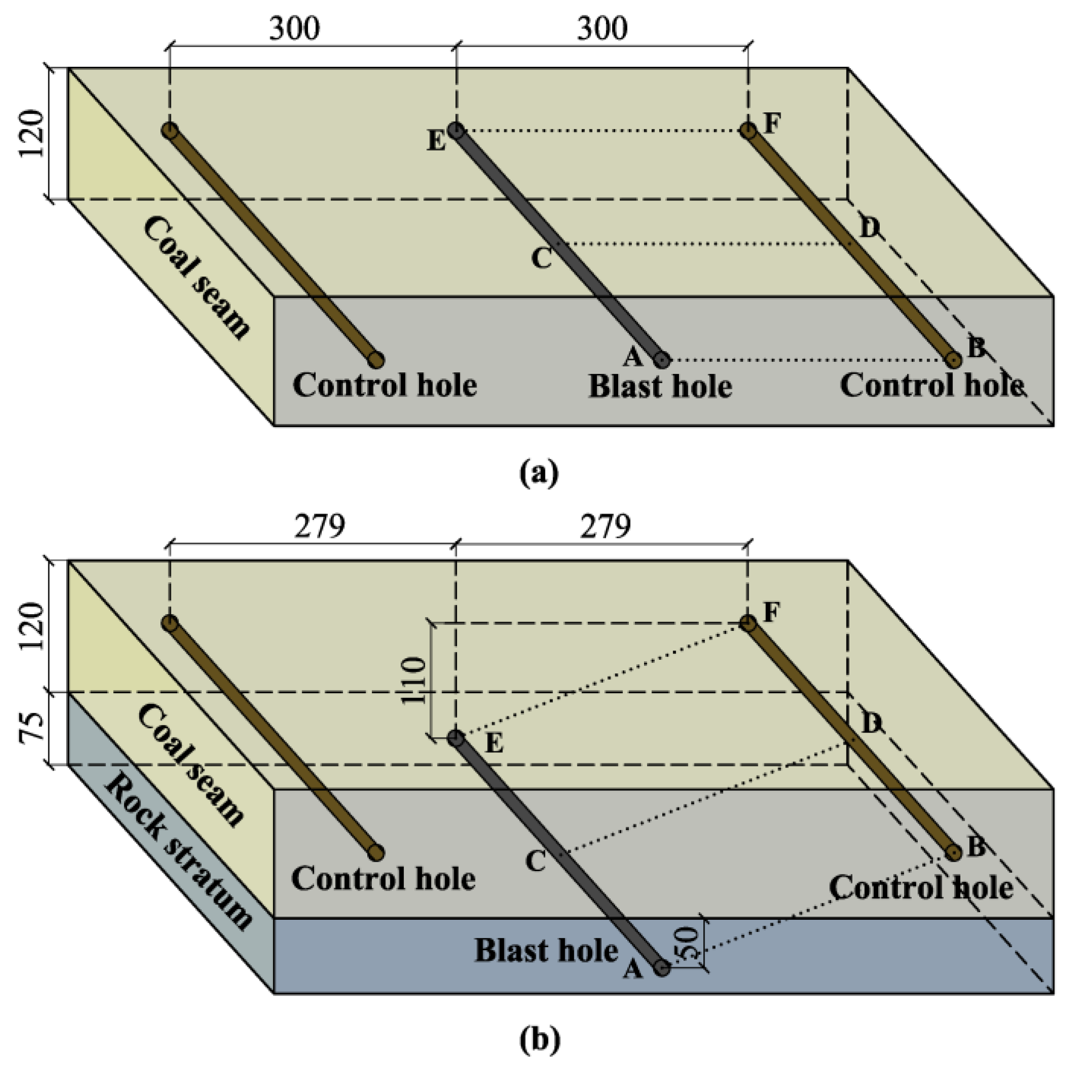
As shown in Figure 14a, the blast hole is coplanar with two control holes when deep-hole blasting occurs in a single coal seam. As shown in Figure 14b, the blast hole is not coplanar with two control holes when blasting in the floor rock stratum. The minimum burden in Figure 14a between the blast hole and the control hole is 3 m in the single media model. The spacing in Figure 14b is 5.58 m between two control holes in the composite media model when keeping the same minimum burden. Since the hole spacing between the control holes in the coal seam increases, the blast hole in the floor rock stratum can be used for gas drainage and lying close to the coal seam. Reasonable parameters lead to a better effect on gas drainage.
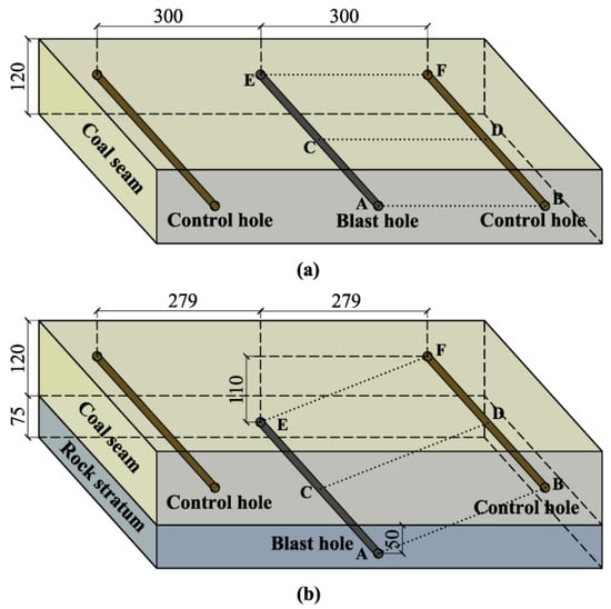
Figure 14.
Difference of hole layout for blasting in coal seam or rock stratum: (a) blast hole lying in coal seam; (b) blast hole lying in rock stratum.
As shown in Figure 14b, the blast hole lies in the floor rock stratum. The blast wave is reflected and transmitted through the interface of the coal-rock seam after initiation. If the spacing (AB, CD and EF) between the blast hole and the control hole is the same as in Figure 14a, the blasting stress on the control hole in the coal-rock media is lower than that in the coal-only media. Therefore, this paper focuses on quantifying this gap and investigating the optimal hole spacing that makes the composite media comparable to the coal-only media.
5.2. Modeling
Modeling with the data measured in the 2709 haulage way of Yuyang Mine, the thickness of the coal seam is 1.2 m, and the blast hole in the rock is arranged at 0.5 m from the floor of the coal seam. The element type is solid 164, and the dynamic plastic material model is adopted. The mechanical parameters of the coal and rock seams are shown in Table 4.

Table 4.
Mechanics parameters of coal and rock in Yuyang Mine.
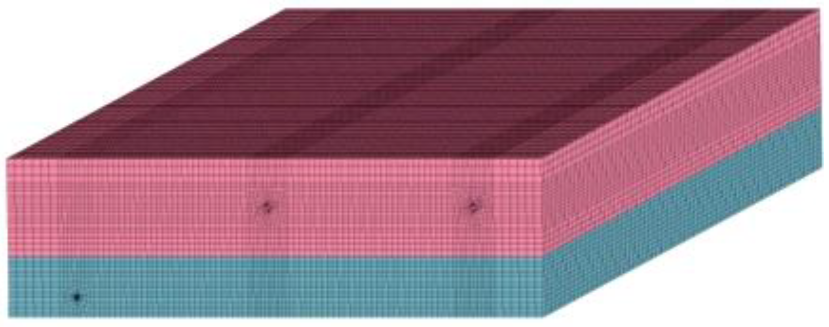
One coal-only model (C model) and four coal-rock models (C-R model, as shown in Figure 15) were established. It helps to find the optimal hole-layout parameters by comparing the effective stresses along the control hole in different media, as shown in Table 5.
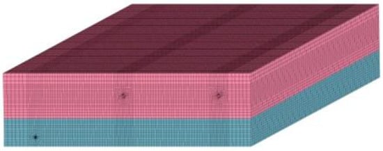
Figure 15.
Computation model for coal-rock media.

Table 5.
Parameters of five models.
5.3. Results Analysis
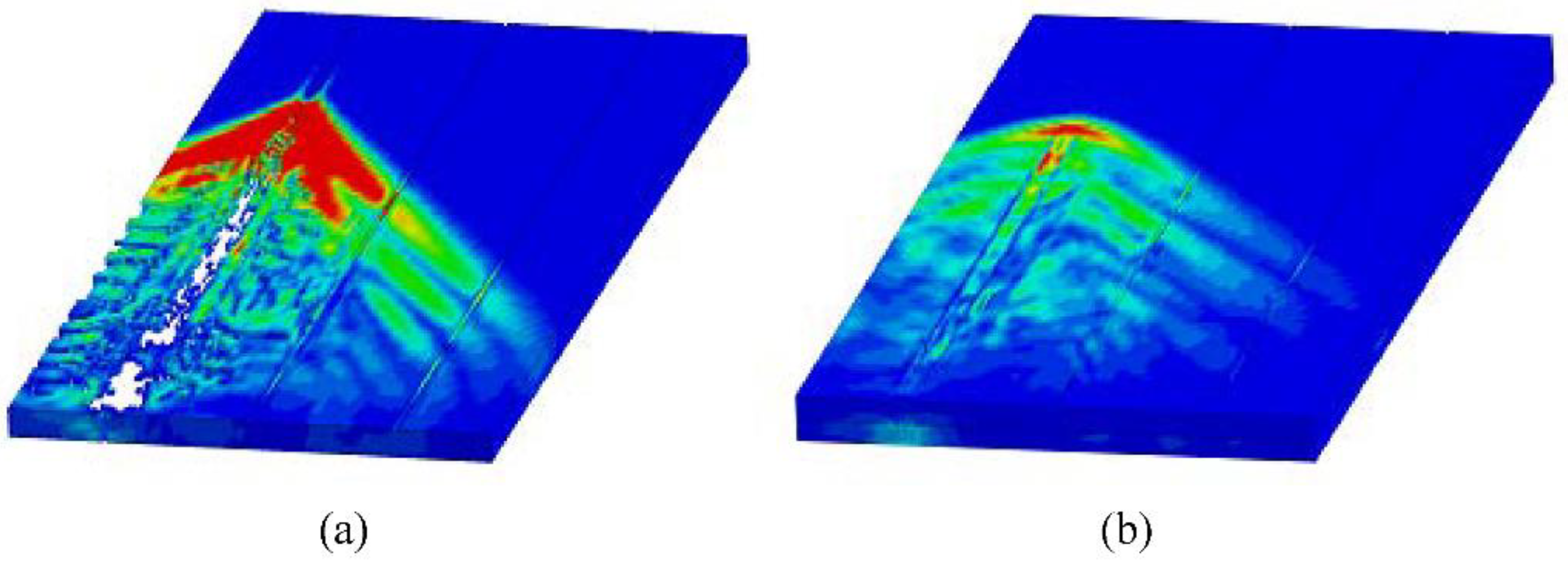
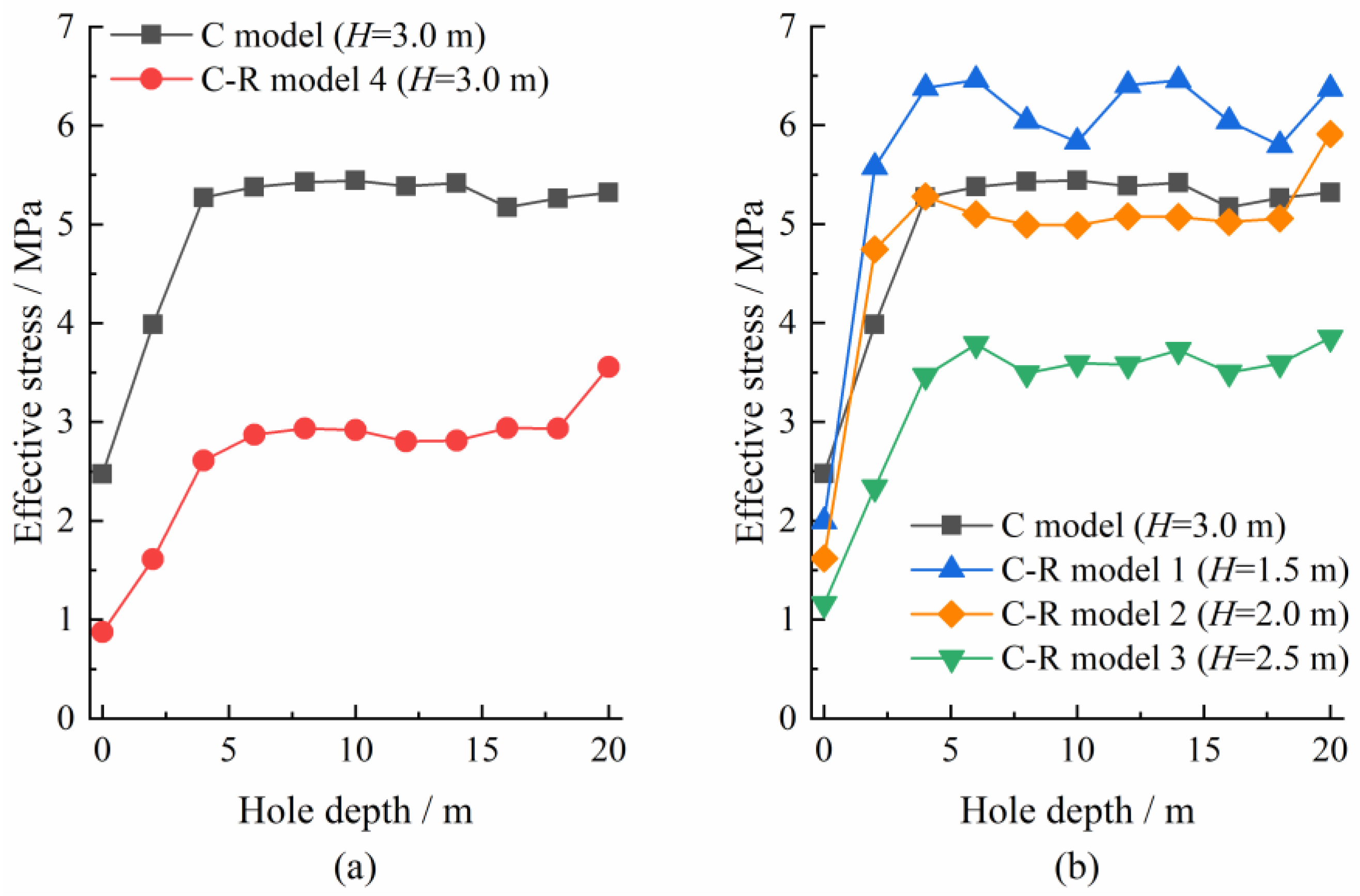
The mechanical characteristics of the five models are calculated. Figure 16 shows the stress cloud map of the C model and the C-R model 4 at 7 ms after initiation. When the hole spacing between the blast and control holes is equal (C model and C-R model 4), it extracts the maximum effective stress along the axis of the control hole. The stress distribution is shown in Figure 17a. The average/maximum value in the coal blasting is 5.0/5.4 MPa, while that in the rock blasting is 2.6/3.6 MPa, reduced by 48/33%. Therefore, for blasting in coal or rock that adopted the same hole spacing, the dynamic stress on the hole in C-R model 4 is reduced more when compared with that in the C model and cannot achieve the same effect.
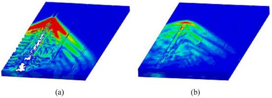
Figure 16.
Three-dimensional cloud of effective stress after blasting at 7 ms: (a) coal-only media; (b) coal-rock media.
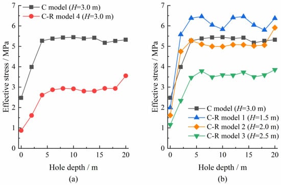
Figure 17.
Comparison of effective stress along the axis of control hole for coal model and coal-rock models: (a) C-R model 4 compared with C model; (b) C-R models 1~3 compared with C model.
To achieve the same blasting stress field as the C model, it needs to reduce the hole spacing in the C-R model between the blast hole and the control hole. Therefore, C-R models 1~3 reduce the hole spacing H in steps of 0.5 m. The distribution of the maximum effective stress is shown in Figure 17b. The average and maximum effective stress along the hole axis is compared in Table 6 between the C model and C-R models 1~3.

Table 6.
Comparison of effective stress along the axis of the control hole for coal-only media and coal-rock media.
As shown in Table 6, the average effective stress of blasting in coal media is 16% lower, 4% higher, and 34% higher in C-R models 1~3 compared with the C model. C-R model 2 is closer to the C model, so it is appropriate to adjust the hole spacing to 2.0 m if the blast hole is laid in rock.
5.4. Verification on Site
Whether the blasting in the rock stratum acting on the coal seam is good or bad can be known only by comparing the effect with that in the coal seam, namely, by verification on-site.
5.4.1. Parameters and Experimental Process
In the 2709 haulage way of Yuyang Mine, three experiments of deep-hole blasting in the floor rock stratum were carried out, and ten blast holes were initiated. Figure 18 shows the hole layout in the first experiment. The actual spacing is 2.2 m between the blast and control holes measured after the operation. Both blast holes start at 0.5 m from the floor of the coal seam, and the inclination angle of the hole is 5°, the same as that of the coal seam.

Figure 18.
Hole layout in the floor drift in Yuyang Mine.
The hole depth of blast holes No. 1 and 2 is 20 m and 25 m, with a diameter of 87 mm. The stemming length is 10 m. The charge density is 1.28 and 1.04 kg/m. The deep-hole blasting for gas drainage is carried out in the same coal seam for comparison.
5.4.2. Test Results
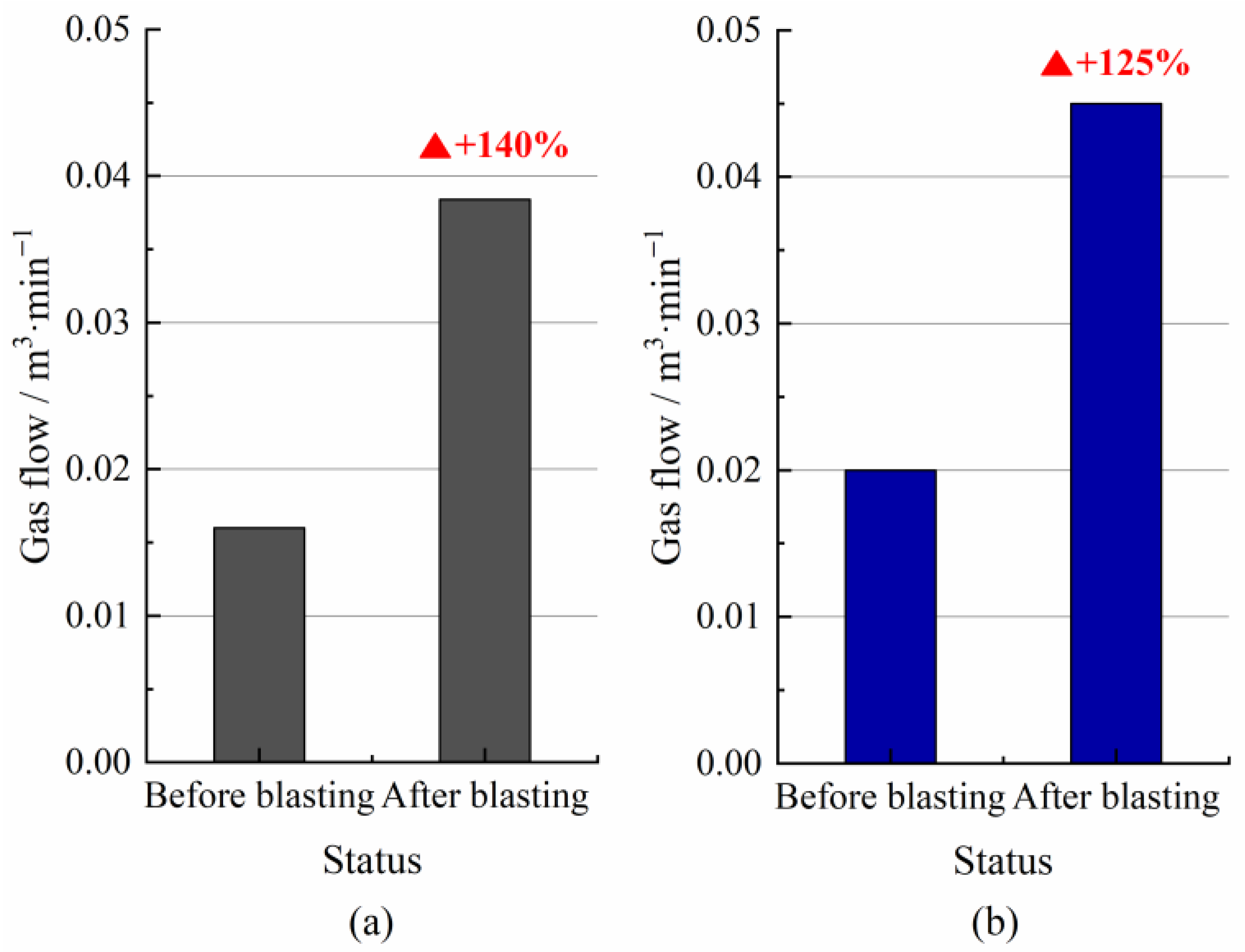
We compared the average gas flow for 20 days before and after blasting in Figure 19. There are two patterns. One is to lay the blast hole in the coal seam with a hole spacing of 3 m. Another is in the rock stratum with a hole spacing of 2 m. In the field experiment, if the blast and control holes lay in the coal seam and did not collapse, the gas drainage effect after blasting is good if the hole spacing is 3.0 m.
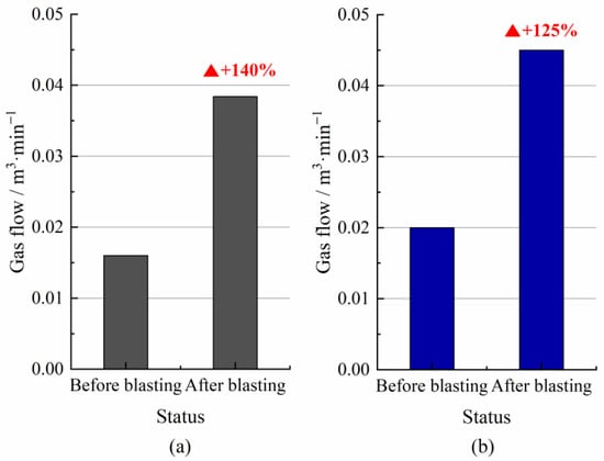
Figure 19.
Comparison of average gas flow before and after blast for coal-only and coal-rock media: (a) coal-only media; (b) coal-rock media.
The two took 1.40 times and 1.25 times higher gas flow after blasting than that before the blasting. It proved that the analysis in theory above and the actual blasting parameters are correct. However, more importantly, drilling and blasting in rock avoids collapsing holes, broadens the applications for deep-hole blasting techniques, and is safer and more effective than drilling and blasting in coal.
5.5. Summary
We improved safety by blasting in the floor rock stratum, solving the difficulty of deep-hole pre-splitting blasting in soft coal seams. Field applications have proven the technology safe and reliable, providing the conditions for many southern mines with soft coal to use deep-hole blasting techniques to improve gas drainage rates.
The optimal spacing between the blast hole and control hole was obtained and verified to be correct in the field. Reducing the spacing between the blast and control holes will increase the dynamic stresses when the blast hole is laid in a rock stratum. Thus, 2 m is used as the hole-layout parameter to maintain the effect on-site.
6. Conclusions
For the technical difficulties of deep-hole blasting technology to achieve gas drainage in complex and variable cases, the solution of classification is proposed. Field applications and numerical simulations are combined to analyze three typical deep-hole blasting techniques and their mechanisms in coal seams, crossing seams, and the floor rock stratum based on the relationship between blast stress field changes and gas flow. Primary parameters are selected for different techniques, and the effectiveness of gas drainage after blasting was confirmed. Based on this, the authors applied deep-hole pre-splitting blasting techniques in the gas control of 26 gassy mines. Deep-hole blasting will become increasingly significant in the future in various domains of gas control. The main conclusions are as follows.
- (1)
- Applying deep-hole blasting in a hard-enough coal seam is the best and simplest method among the three. However, when the coal seam is soft, the increase in gas drainage rate is limited after blasting. We can obtain two crucial parameters for that in the coal seam. They are the radius of the blast-induced crushing zone and the spacing between the blast hole and control hole to ensure the drainage effect.
- (2)
- The deep hole crosses multiple seams when solving the uncovering coal in crosscuts and outburst elimination in local areas. With the increase in the effective stress acting on the control hole, the volume of gas drainage increases significantly. Since effective stress is related to the spacing between the control and blast holes, the spacing at the hole’s entrance and bottom are crucial parameters when the holes cross the coal seams.
- (3)
- When the coal seam is so soft as to cause the collapse of the blast hole, it is better to drill a deep hole in the floor rock stratum. This method requires obtaining the range of the transmitted stress field when the rock blasting propagates to the coal. The hole spacing between the blast hole in the rock and the control hole in the coal is determined based on the idea that the effective stresses through the coal-rock medium acting on the control holes are equal to that in the coal-only medium. The practice has proved the effectiveness of adjusting this blasting parameter.
Author Contributions
Conceptualization, M.G.; methodology, M.G., H.W. and X.W.; validation, H.W. and X.W.; formal analysis, X.W. and H.W.; investigation, M.G.; writing—original draft preparation, M.G.; writing—review and editing, H.W., M.G. and X.W.; visualization, H.W., X.W. and Y.G.; supervision, M.G.; project administration, M.G.; funding acquisition, Y.G. All authors have read and agreed to the published version of the manuscript.
Funding
This research was funded by the Fundamental Research Funds for the Central Universities, grant number FRF-TP-20-095A1.
Data Availability Statement
Not applicable.
Conflicts of Interest
The authors declare no conflict of interest.
References
- Amani, K.; Najafi, M.; Rafiee, R. Prediction of coal and gas outburst risk by fuzzy rock engineering system. Environ. Earth Sci. 2021, 80, 491. [Google Scholar] [CrossRef]
- Szlązak, N.; Obracaj, D.; Swolkień, J. Enhancing safety in the Polish high-methane coal mines: An overview. Min. Metall. Explor. 2020, 37, 567–579. [Google Scholar] [CrossRef]
- Zhou, X.; Li, X.; Bai, G.; Chai, L.; Wang, Y.; Xiao, M.; Xia, S. Research method of pressure relief and permeability enhancement in low permeability coal seam: A review. AIP Adv. 2022, 12, 010702. [Google Scholar] [CrossRef]
- Bibler, C.J.; Marshall, J.S.; Pilcher, R.C. Status of worldwide coal mine methane emissions and use. Int. J. Coal Geol. 1998, 35, 283–310. [Google Scholar] [CrossRef]
- Karacan, C.Ö.; Ruiz, F.A.; Cotè, M.; Phipps, S. Coal mine methane: A review of capture and utilization practices with benefits to mining safety and to greenhouse gas reduction. Int. J. Coal Geol. 2011, 86, 121–156. [Google Scholar] [CrossRef]
- Wang, F.; Ren, T.; Tu, S.; Hungerford, F.; Aziz, N. Implementation of underground longhole directional drilling technology for greenhouse gas mitigation in Chinese coal mines. Int. J. Greenh. Gas Control 2012, 11, 290–303. [Google Scholar] [CrossRef]
- Chu, H.; Yang, X.; Wang, C.; Liang, W. Study on the coal damage and fracture mechanism under multiple actions of blasting stress wave. Arab. J. Sci. Eng. 2021, 46, 10847–10854. [Google Scholar] [CrossRef]
- Zhu, W.C.; Wei, C.H.; Li, S.; Wei, J.; Zhang, M.S. Numerical modeling on destress blasting in coal seam for enhancing gas drainage. Int. J. Rock Mech. Min. Sci. 2013, 59, 179–190. [Google Scholar] [CrossRef]
- Huang, C.G.; Zhang, Y.B.; He, J.F.; Luo, Y.; Sun, Z.G. Permeability improvements of an outburst-prone coal seam by means of presplitting and blasting with multiple deep boreholes. Energy Sci. Eng. 2019, 7, 2223–2236. [Google Scholar] [CrossRef]
- Chen, X.; Xue, S.; Yuan, L. Coal seam drainage enhancement using borehole presplitting basting technology—A case study in Huainan. Int. J. Min. Sci. Technol. 2017, 27, 771–775. [Google Scholar] [CrossRef]
- Xie, Z.; Zhang, D.; Song, Z.; Li, M.; Liu, C.; Sun, D. Optimization of drilling layouts based on controlled presplitting blasting through strata for gas drainage in coal roadway strips. Energies 2017, 10, 1228. [Google Scholar] [CrossRef]
- Yue, G.; Li, M.; Wang, L.; Liang, W. Optimal layout of blasting holes in structural anisotropic coal seam. PLoS ONE 2019, 14, e0218105. [Google Scholar] [CrossRef] [PubMed]
- Ti, Z.; Zhang, F.; Pan, J.; Ma, X.; Shang, Z. Permeability enhancement of deep hole pre-splitting blasting in the low permeability coal seam of the Nanting coal mine. PLoS ONE 2018, 13, e0199835. [Google Scholar] [CrossRef] [PubMed]
- Wang, W.; Wei, Y.; Guo, M.; Li, Y. Coupling technology of deep-hole presplitting blasting and hydraulic fracturing enhance permeability technology in low-permeability and gas outburst coal seam: A case study in the no. 8 mine of Pingdingshan, China. Adv. Civ. Eng. 2021, 2021, 5569678. [Google Scholar] [CrossRef]
- Li, P.; Zhang, X.; Li, H. Technology of coupled permeability enhancement of hydraulic punching and deep-hole pre-splitting blasting in a “three-soft” coal seam. Mater. Tehnol. 2021, 55, 89–96. [Google Scholar] [CrossRef]
- Jia, L.; Peng, S.; Xu, J.; Yan, F.; Chen, J.; Wu, B. Investigation on gas drainage effect under different borehole layout via 3D monitoring of gas pressure. J. Nat. Gas Sci. Eng. 2022, 101, 104522. [Google Scholar] [CrossRef]
- Liu, J.; Wang, H.; Yuan, Z.; Fan, X. Experimental study of pre-splitting blasting enhancing pre-drainage rate of low permeability heading face. Procedia Eng. 2011, 26, 818–823. [Google Scholar] [CrossRef]
- Liu, Z.; Zhang, Y.; Huang, Z.; Gao, Y.; Zhang, Y. Numerical simulating research on orifice pre-splitting blasting in coal seam. Procedia Eng. 2012, 45, 322–328. [Google Scholar] [CrossRef]
- Li, M.; Jiang, B.; Lin, S.; Lan, F.; Wang, J. Structural controls on coalbed methane reservoirs in Faer coal mine, Southwest China. J. Earth Sci. 2013, 24, 437–448. [Google Scholar] [CrossRef]
- Li, Q.; He, X.; Wu, J.; Ma, S. Investigation on coal seam distribution and gas occurrence law in Guizhou, China. Energy Explor. Exploit. 2018, 36, 1310–1334. [Google Scholar] [CrossRef]
Publisher’s Note: MDPI stays neutral with regard to jurisdictional claims in published maps and institutional affiliations. |
© 2022 by the authors. Licensee MDPI, Basel, Switzerland. This article is an open access article distributed under the terms and conditions of the Creative Commons Attribution (CC BY) license (https://creativecommons.org/licenses/by/4.0/).

