
Performance Comparison of Mini-Rectangular Fin Heat Sinks Using Different Coolants: Supercritical CO2, Water and Al2O3/H2O Nanofluid

 , , , , and
Abstract
:1. Introduction
2. Case Study and Numerical Model
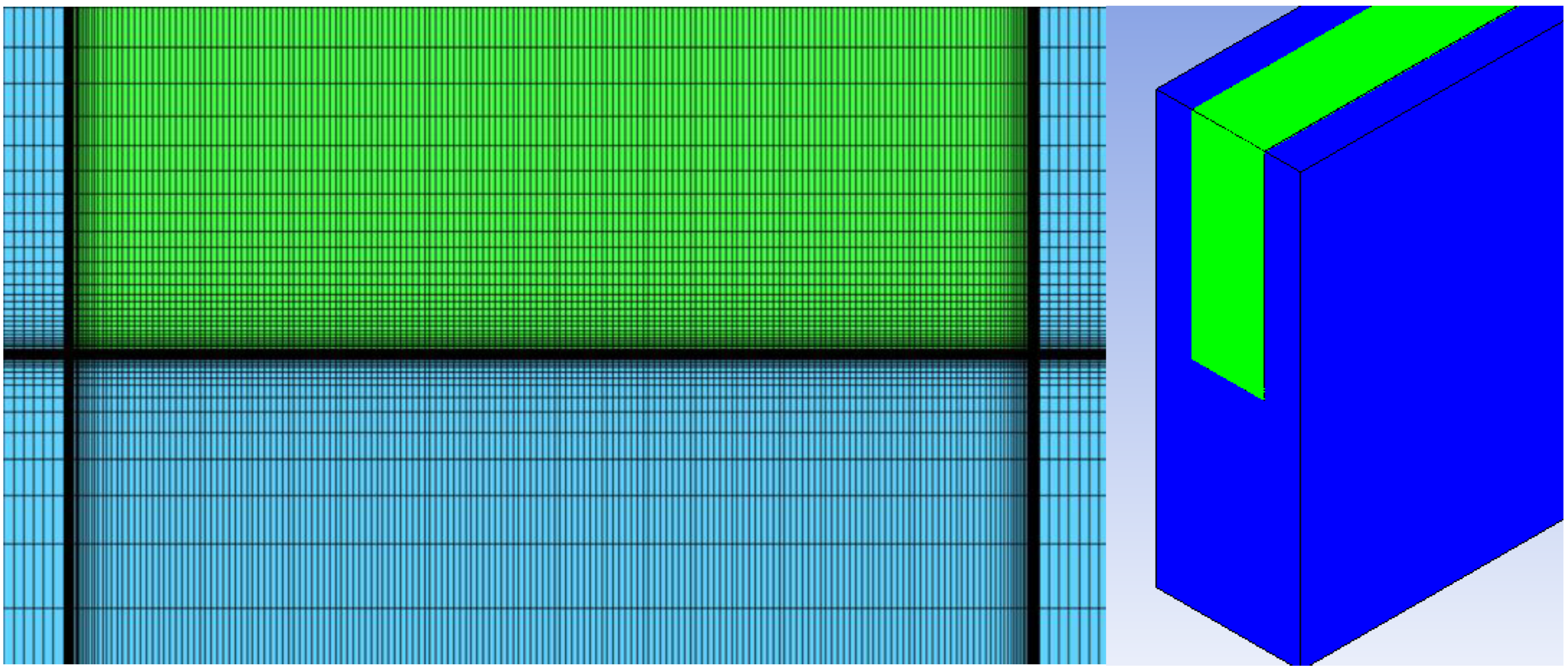
2.1. Numerical Model
2.2. Mesh Optimization
2.3. Model Validation
3. Results and Discussion
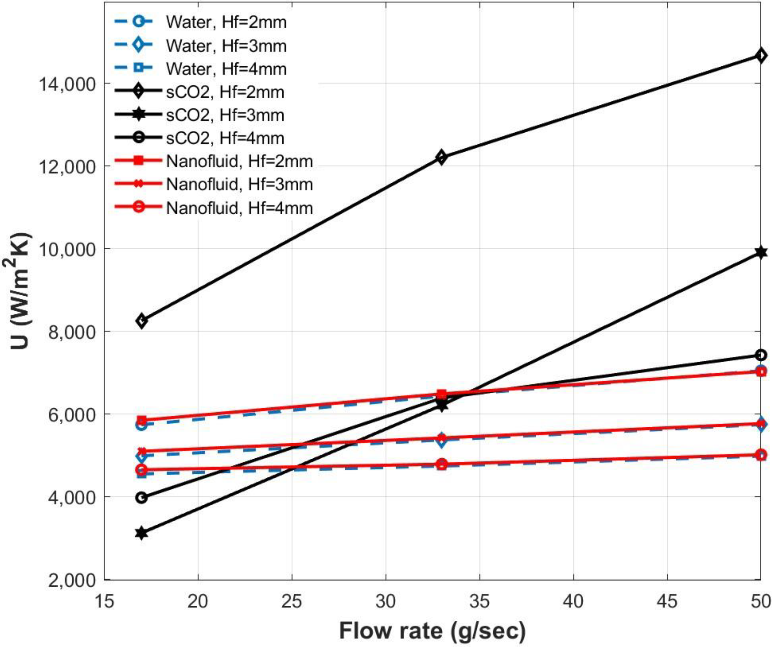
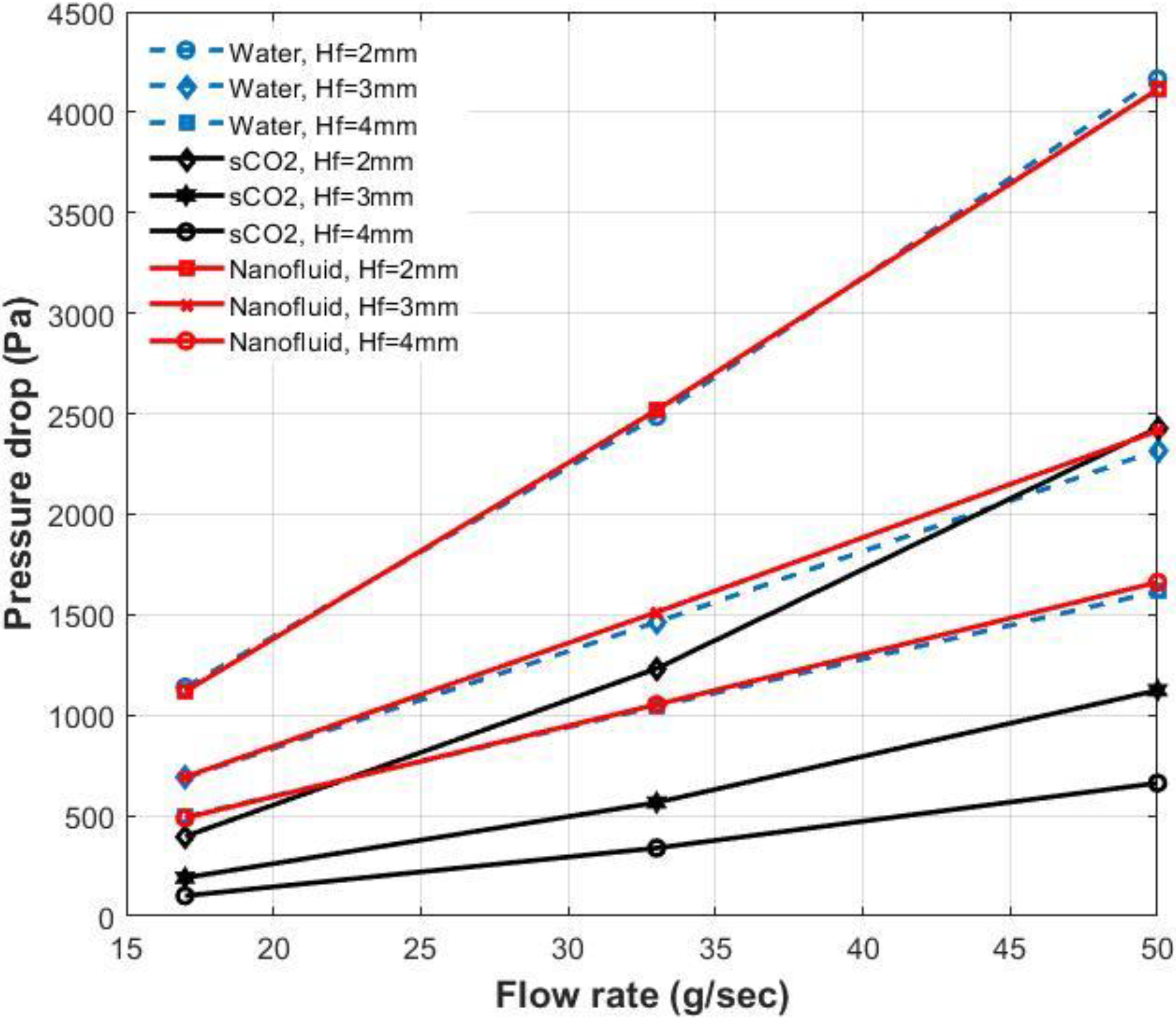
3.1. Fin Height
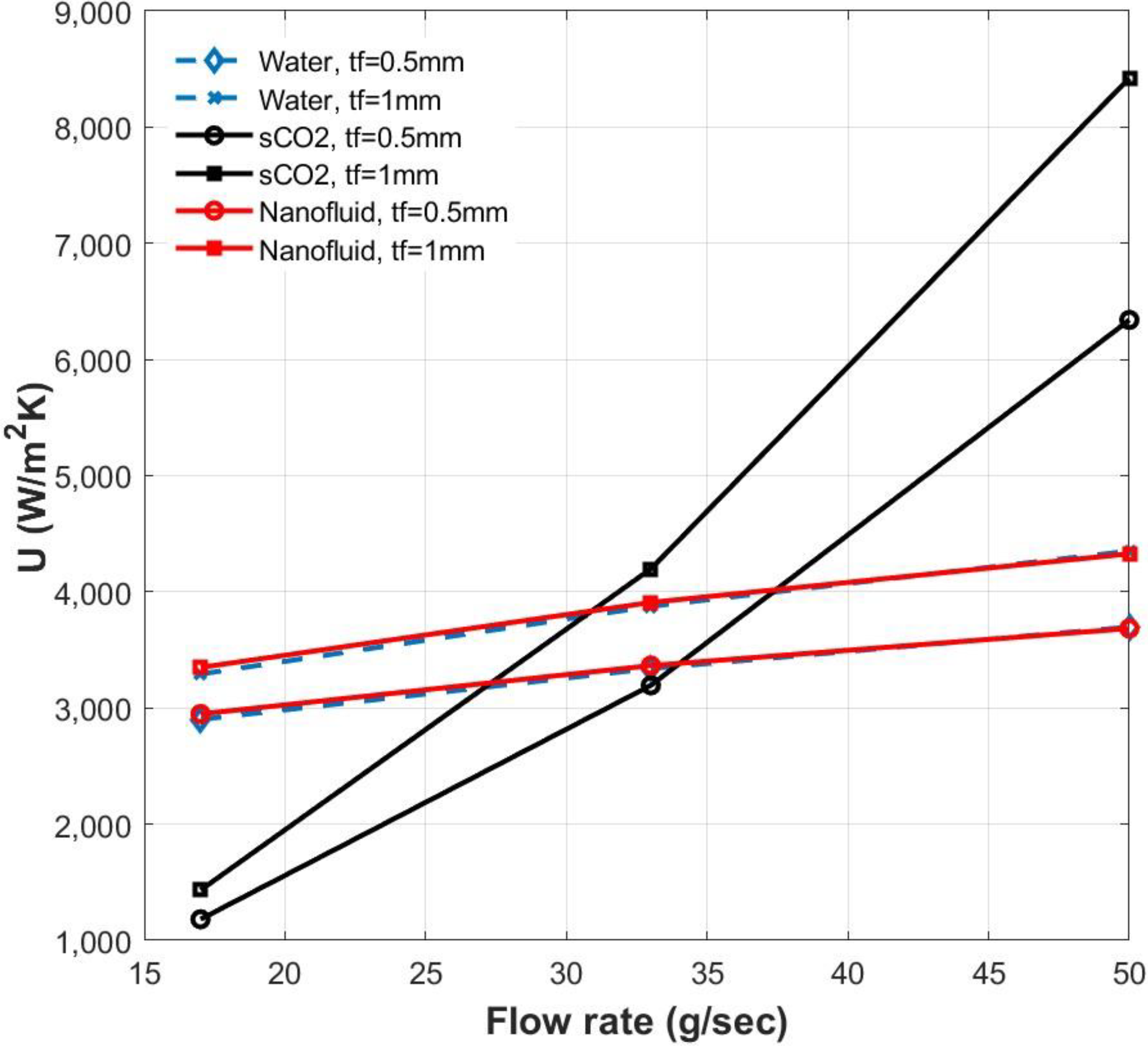
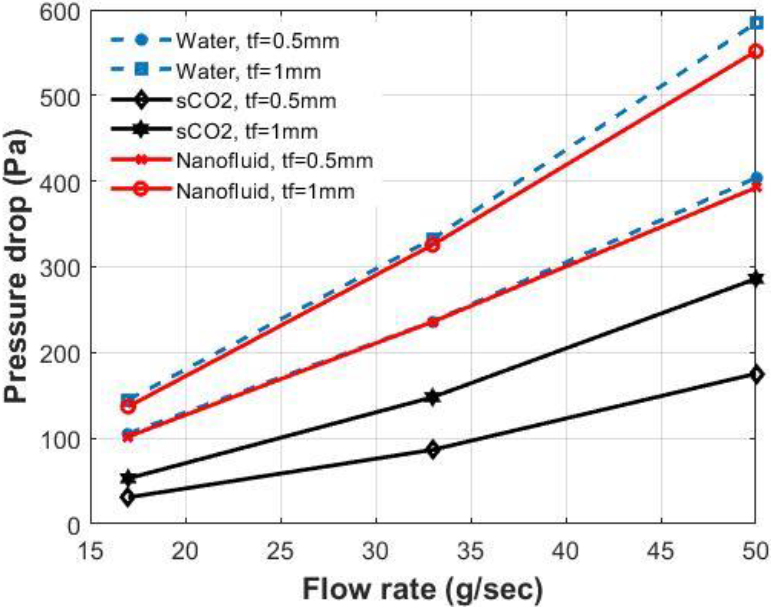
3.2. Fin Thickness
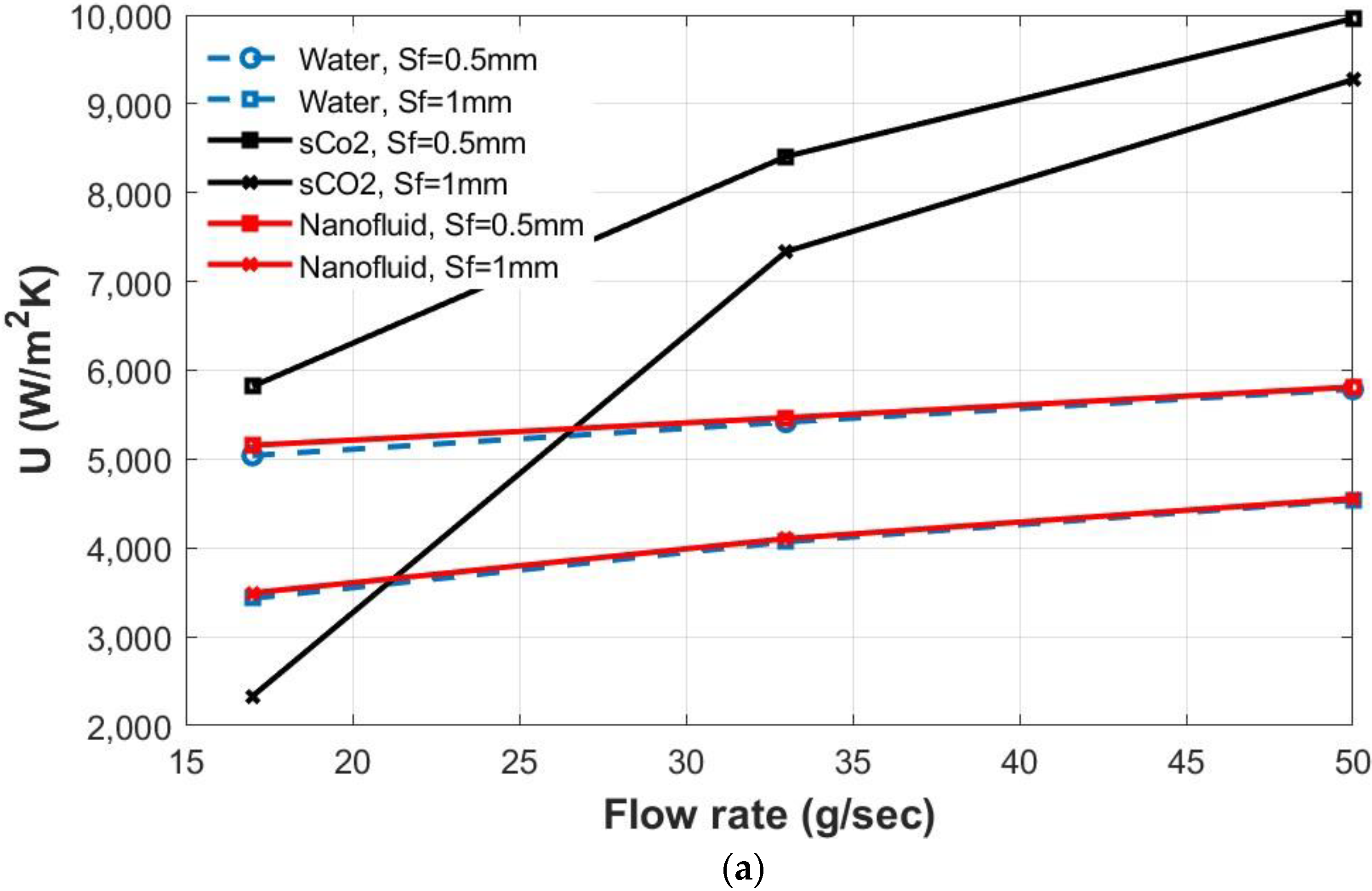
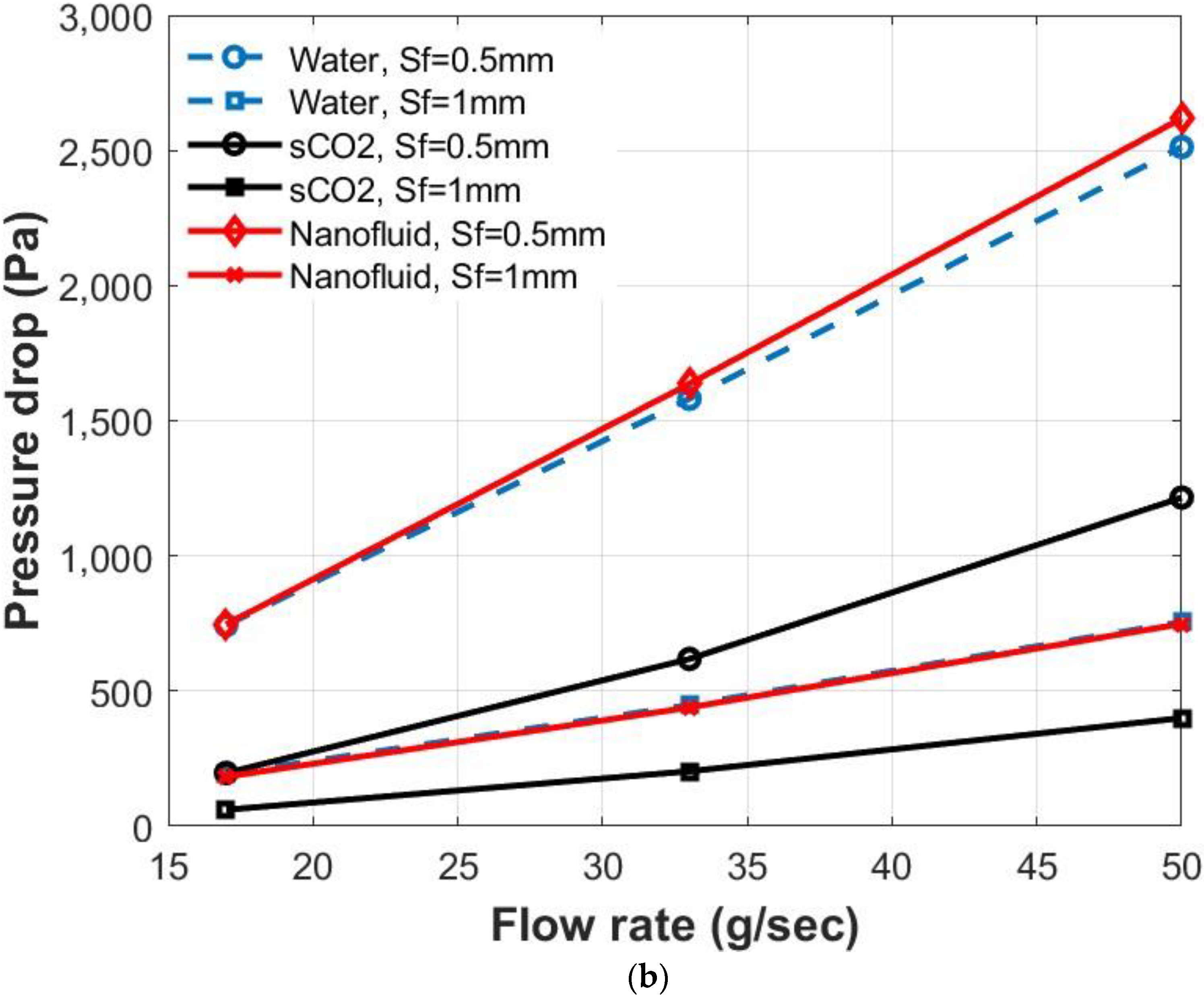
3.3. Fin Spacing
3.4. Performance Evaluation Criteria (PEC)
4. Conclusions
- For all coolants, increasing the flowrate increases both the overall heat transfer coefficient (CHT) and the pressure drop (ΔP).
- Increasing the fin height and spacing deteriorates the heat sink’s thermal performance by reducing the CHT; however, it enhances the hydraulic performance.
- Fin thickness reduction has a beneficial influence on ΔP. Still, its effect on the heat sink’s thermal performance is almost negligible compared to the impact of variations in fin spacing and mass flow rate.
- The sCO2 shows enhanced performance regarding elevated CHT and reduced ΔP compared to the water and nanofluid. Moreover, the performance evaluation criterion (PEC) for the sCO2 is higher than that for the water and nanofluid by 53% at 17 g/s flowrate and 243% at 50 g/s flowrate.
Author Contributions
Funding
Acknowledgments
Conflicts of Interest
Nomenclature
| Ai | Interfacial area between fluid and solid domain [mm2] |
| Hydraulic diameter [mm] | |
| Heat flux through cell-interface [W m−2] | |
| Total heat flux through the fluid-solid interface [W m−2] | |
| Friction factor | |
| ΔP | Pressure drop [Pa] |
| U | Overall heat transfer coefficient [Wm−2 K−1] |
| Hf | Fin height [mm] |
| Sf | Fin pacing [mm] |
| Lf | Fin length [mm] |
| tf | Fin thickness [mm] |
| T | Temperature [K] |
| Cp | Specific heat capacity [J kg−1 K−1] |
| Pr | Prandtl number |
| ṁ | Mass flow rate [g s−1] |
| Re | Reynolds number |
| u | Velocity [m s−1] |
| k | Thermal conductivity [W m−1 K−1] |
| Greek symbols | |
| ϕ | Volume fraction of nanoparticles |
| μ | Dynamic viscosity [kg m−1 s−1] |
| Density [kg m−3] | |
| Sub and super scripts | |
| p | Particulate |
| s | Solid |
| Base fluid | |
| Effective | |
| i | Inlet |
| b | Base |
| o | Outlet |
| Abbreviations | |
| LMTD | Logarithmic mean temperature difference [K] |
| PEC | Performance evaluation criterion |
| sCO2 | Supercritical carbon dioxide |
References
- Baird, E.; Mohseni, K. Digitized Heat Transfer: A New Paradigm for Thermal Management of Compact Micro Systems. IEEE Trans. Compon. Packag. Technol. 2008, 31, 143–151. [Google Scholar] [CrossRef]
- Erbas, N.; Baysal, O. Micron-Level Actuators for Thermal Management of Microelectronic Devices. Heat Transf. Eng. 2009, 30, 138–147. [Google Scholar] [CrossRef]
- Saeed, M.; Berrouk, A.S.; Al Shehhi, M.S.; Al Wahedi, Y.F. Numerical investigation of the thermohydraulic characteristics of microchannel heat sinks using supercritical CO2 as a coolant. J. Supercrit. Fluids 2021, 176, 105306. [Google Scholar] [CrossRef]
- Li, J.; Peterson, G.P. 3-Dimensional numerical optimization of silicon-based high performance parallel microchannel heat sink with liquid flow. Int. J. Heat Mass Transf. 2007, 50, 2895–2904. [Google Scholar] [CrossRef]
- Chai, L.; Xia, G.; Wang, L.; Zhou, M.; Cui, Z. Heat transfer enhancement in microchannel heat sinks with periodic expansion–constriction cross-sections. Int. J. Heat Mass Transf. 2013, 62, 741–751. [Google Scholar] [CrossRef]
- Zhang, F.; Wu, B.; Du, B. Heat transfer optimization based on finned microchannel heat sink. Int. J. Therm. Sci. 2022, 172, 107357. [Google Scholar] [CrossRef]
- Kumar, S.; Singh, P.K. A novel approach to manage temperature non-uniformity in minichannel heat sink by using intentional flow maldistribution. Appl. Therm. Eng. 2019, 163, 114403. [Google Scholar] [CrossRef]
- Khoshvaght-Aliabadi, M.; Sahamiyan, M.; Hesampour, M.; Sartipzadeh, O. Experimental study on cooling performance of sinusoidal–wavy minichannel heat sink. Appl. Therm. Eng. 2016, 92, 50–61. [Google Scholar] [CrossRef]
- Khoshvaght-Aliabadi, M.; Feizabadi, A.; Nouri, M. Design of novel geometries for minichannels to reduce junction temperature of heat sinks and enhance temperature uniformity. Appl. Therm. Eng. 2021, 192, 116926. [Google Scholar] [CrossRef]
- Chai, L.; Wang, L.; Bai, X. Thermohydraulic performance of microchannel heat sinks with triangular ribs on sidewalls–Part 2: Average fluid flow and heat transfer characteristics. Int. J. Heat Mass Transf. 2019, 128, 634–648. [Google Scholar] [CrossRef]
- Awais, A.A.; Saeed, M.; Kim, M.-H. Performance enhancement in minichannel heat sinks using supercritical carbon dioxide (sCO2) as a coolant. Int. J. Heat Mass Transf. 2021, 177, 121539. [Google Scholar] [CrossRef]
- Gong, L.; Kota, K.; Tao, W.; Joshi, Y. Parametric numerical study of flow and heat transfer in microchannels with wavy walls. J. Heat Transf. 2011, 133, 051702. [Google Scholar] [CrossRef]
- Wang, Z.-H.; Wang, X.-D.; Yan, W.-M.; Duan, Y.-Y.; Lee, D.-J.; Xu, J.-L. Multi-parameters optimization for microchannel heat sink using inverse problem method. Int. J. Heat Mass Transf. 2011, 54, 2811–2819. [Google Scholar] [CrossRef]
- Caney, N.; Marty, P.; Bigot, J. Friction losses and heat transfer of single-phase flow in a mini-channel. Appl. Therm. Eng. 2007, 27, 1715–1721. [Google Scholar] [CrossRef] [Green Version]
- Tullius, J.; Tullius, T.K.; Bayazitoglu, Y. Optimization of short micro pin fins in minichannels. Int. J. Heat Mass Transf. 2012, 55, 3921–3932. [Google Scholar] [CrossRef]
- Xie, X.; Liu, Z.; He, Y.; Tao, W. Numerical study of laminar heat transfer and pressure drop characteristics in a water-cooled minichannel heat sink. Appl. Therm. Eng. 2009, 29, 64–74. [Google Scholar] [CrossRef]
- Naphon, P.; Wongwises, S. Investigation on the jet liquid impingement heat transfer for the central processing unit of personal computers. Int. Commun. Heat Mass Transf. 2010, 37, 822–826. [Google Scholar] [CrossRef]
- Panão, M.; Guerreiro, J.; Moreira, A. Microprocessor cooling based on an intermittent multijet spray system. Int. J. Heat Mass Transf. 2012, 55, 2854–2863. [Google Scholar] [CrossRef]
- Hu, H.; Ge, T.; Dai, Y.; Wang, R. Experimental study on water-cooled thermoelectric cooler for CPU under severe environment. Int. J. Refrig. 2016, 62, 30–38. [Google Scholar] [CrossRef]
- Wang, X.-D.; Bin, A.; Xu, J.-L. Optimal geometric structure for nanofluid-cooled microchannel heat sink under various constraint conditions. Energy Convers. Manag. 2013, 65, 528–538. [Google Scholar] [CrossRef]
- Peyghambarzadeh, S.; Hashemabadi, S.; Chabi, A.; Salimi, M. Performance of water based CuO and Al2O3 nanofluids in a Cu–Be alloy heat sink with rectangular microchannels. Energy Convers. Manag. 2014, 86, 28–38. [Google Scholar] [CrossRef]
- Roberts, N.A.; Walker, D. Convective performance of nanofluids in commercial electronics cooling systems. Appl. Therm. Eng. 2010, 30, 2499–2504. [Google Scholar] [CrossRef]
- Rafati, M.; Hamidi, A.; Niaser, M.S. Application of nanofluids in computer cooling systems (heat transfer performance of nanofluids). Appl. Therm. Eng. 2012, 45, 9–14. [Google Scholar] [CrossRef]
- Jajja, S.A.; Ali, W.; Ali, H.M.; Ali, A.M. Water cooled minichannel heat sinks for microprocessor cooling: Effect of fin spacing. Appl. Therm. Eng. 2014, 64, 76–82. [Google Scholar] [CrossRef]
- Ho, C.-J.; Chen, W.-C.; Yan, W.-M. Experimental study on cooling performance of minichannel heat sink using water-based MEPCM particles. Int. Commun. Heat Mass Transf. 2013, 48, 67–72. [Google Scholar] [CrossRef]
- Naphon, P.; Nakharintr, L. Heat transfer of nanofluids in the mini-rectangular fin heat sinks. Int. Commun. Heat Mass Transf. 2013, 40, 25–31. [Google Scholar] [CrossRef]
- Ijam, A.; Saidur, R.; Ganesan, P. Cooling of minichannel heat sink using nanofluids. Int. Commun. Heat Mass Transf. 2012, 39, 1188–1194. [Google Scholar] [CrossRef]
- Rimbault, B.; Nguyen, C.; Galanis, N. Experimental investigation of CuO–water nanofluid flow and heat transfer inside a microchannel heat sink. Int. J. Therm. Sci. 2014, 84, 275–292. [Google Scholar] [CrossRef]
- Keshavarz Moraveji, M.; Mohammadi Ardehali, R.; Ijam, A. CFD investigation of nanofluid effects (cooling performance and pressure drop) in mini-channel heat sink. Int. Commun. Heat Mass Transf. 2013, 40, 58–66. [Google Scholar] [CrossRef]
- Afrand, M. Experimental study on thermal conductivity of ethylene glycol containing hybrid nano-additives and development of a new correlation. Appl. Therm. Eng. 2017, 110, 1111–1119. [Google Scholar] [CrossRef]
- Dominic, A.; Devahdhanush, V.; Suresh, S. An experimental investigation on the effect of relative waviness on performance of minichannel heat sinks using water and nanofluids. Heat Mass Transf. 2022, 58, 247–262. [Google Scholar] [CrossRef]
- Babar, H.; Wu, H.; Ali, H.M.; Shah, T.R.; Zhang, W. Staggered oriented airfoil shaped pin-fin heat sink: Investigating the efficacy of novel water based ferric oxide-silica hybrid nanofluid. Int. J. Heat Mass Transf. 2022, 194, 123085. [Google Scholar] [CrossRef]
- Bazkhane, S.; Zahmatkesh, I. Taguchi–based sensitivity analysis of hydrodynamics and heat transfer of nanofluids in a microchannel heat sink (MCHS) having porous substrates. Int. Commun. Heat Mass Transf. 2020, 118, 104885. [Google Scholar] [CrossRef]
- Nemati, H. A general equation based on entropy generation minimization to optimize plate fin heat sink. Eng. J. 2018, 22, 159–174. [Google Scholar] [CrossRef]
- Chai, L.; Shaukat, R.; Wang, L.; Wang, H.S. A review on heat transfer and hydrodynamic characteristics of nano/microencapsulated phase change slurry (N/MPCS) in mini/microchannel heat sinks. Appl. Therm. Eng. 2018, 135, 334–349. [Google Scholar] [CrossRef] [Green Version]
- Saeed, M.; Kim, M.-H. Heat transfer enhancement using nanofluids (Al2O3-H2O) in mini-channel heatsinks. Int. J. Heat Mass Transf. 2018, 120, 671–682. [Google Scholar] [CrossRef]
- Fronk, B.M.; Rattner, A.S. High-flux thermal management with supercritical fluids. J. Heat Transf. 2016, 138, 124501. [Google Scholar] [CrossRef]
- Jung, S.Y.; Park, H. Experimental investigation of heat transfer of Al2O3 nanofluid in a microchannel heat sink. Int. J. Heat Mass Transf. 2021, 179, 121729. [Google Scholar] [CrossRef]
- Bahiraei, M.; Monavari, A.; Naseri, M.; Moayedi, H. Irreversibility characteristics of a modified microchannel heat sink operated with nanofluid considering different shapes of nanoparticles. Int. J. Heat Mass Transf. 2020, 151, 119359. [Google Scholar] [CrossRef]
- Yan, W.-M.; Ho, C.J.; Tseng, Y.-T.; Qin, C.; Rashidi, S. Numerical study on convective heat transfer of nanofluid in a minichannel heat sink with micro-encapsulated PCM-cooled ceiling. Int. J. Heat Mass Transf. 2020, 153, 119589. [Google Scholar] [CrossRef]
- Ho, C.J.; Liao, J.-C.; Yan, W.-M.; Amani, M. Experimental study of transient thermal characteristics of nanofluid in a minichannel heat sink with MEPCM layer in its ceiling. Int. J. Heat Mass Transf. 2019, 133, 1041–1051. [Google Scholar] [CrossRef]
- Chummar, A.; Harish, R. CFD simulation of laminar free convection flows of nanofluids in a cubical enclosure. Mater. Today Proc. 2022, 51, 1473–1481. [Google Scholar] [CrossRef]
- Ansys. Inc. ANSYS, ANSYS CFX-Solver Theory Guide; Ansys. Inc.: Canonsburg, PA, USA, 2011. [Google Scholar]
- Saeed, M.; Kim, M.-H. Numerical study on thermal hydraulic performance of water cooled mini-channel heat sinks. Int. J. Refrig. 2016, 69, 147–164. [Google Scholar] [CrossRef]


| Fin thickness tf (mm) | 0.5 and 1 |
| Fin spacing Sf (mm) | 0.5 and 1 |
| Fin height Hf (mm) | 2, 3 and 4 |
| Fin length Lf (mm) | 45 |
| Number of channels | 28, 37 and 55 |
| Mass flowrates (g/s) | 17, 33 and 50 |
| M1 | M2 | M3 | M4 | |
|---|---|---|---|---|
| NE along Sf | 15 | 30 | 40 | 50 |
| NE along Lf | 60 | 85 | 100 | 120 |
| NE along Hf | 20 | 35 | 45 | 55 |
| No. of nodes | 111,300 | 291,550 | 473,000 | 747,600 |
| (°C) | 44.92 | 44.85 | 44.81 | 44.77 |
| ∆P (kpa) | 8.47 | 9.07 | 9.27 | 9.38 |
| U (W/m2K) | 3716.3 | 3818.32 | 3849.82 | 3881.99 |
| Space on disk (MB) | 182.19 | 359.1 | 559.97 | 863.98 |
| CPU time/iteration (s) | 0.81 | 3.38 | 6.42 | 10.38 |
Publisher’s Note: MDPI stays neutral with regard to jurisdictional claims in published maps and institutional affiliations. |
© 2022 by the authors. Licensee MDPI, Basel, Switzerland. This article is an open access article distributed under the terms and conditions of the Creative Commons Attribution (CC BY) license (https://creativecommons.org/licenses/by/4.0/).
Share and Cite
Alemam, A.; Yehya, S.A.; Omer, A.S.; Hamza, A.; Saeed, M.; Berrouk, A.S. Performance Comparison of Mini-Rectangular Fin Heat Sinks Using Different Coolants: Supercritical CO2, Water and Al2O3/H2O Nanofluid. Energies 2022, 15, 8734. https://doi.org/10.3390/en15228734
Alemam A, Yehya SA, Omer AS, Hamza A, Saeed M, Berrouk AS. Performance Comparison of Mini-Rectangular Fin Heat Sinks Using Different Coolants: Supercritical CO2, Water and Al2O3/H2O Nanofluid. Energies. 2022; 15(22):8734. https://doi.org/10.3390/en15228734
Chicago/Turabian StyleAlemam, Asem, Sherif A. Yehya, Abubaker S. Omer, Ameer Hamza, Muhammed Saeed, and Abdallah S. Berrouk. 2022. "Performance Comparison of Mini-Rectangular Fin Heat Sinks Using Different Coolants: Supercritical CO2, Water and Al2O3/H2O Nanofluid" Energies 15, no. 22: 8734. https://doi.org/10.3390/en15228734