
On the Employment of a Chloride or Fluoride Salt Fuel System in Advanced Molten Salt Reactors, Part 1: Thermophysical Properties and Core Criticality
 , , and
Abstract
:1. Introduction
2. Simulation
3. Results and Discussions
3.1. Thermophysical Properties of Salt Fuel
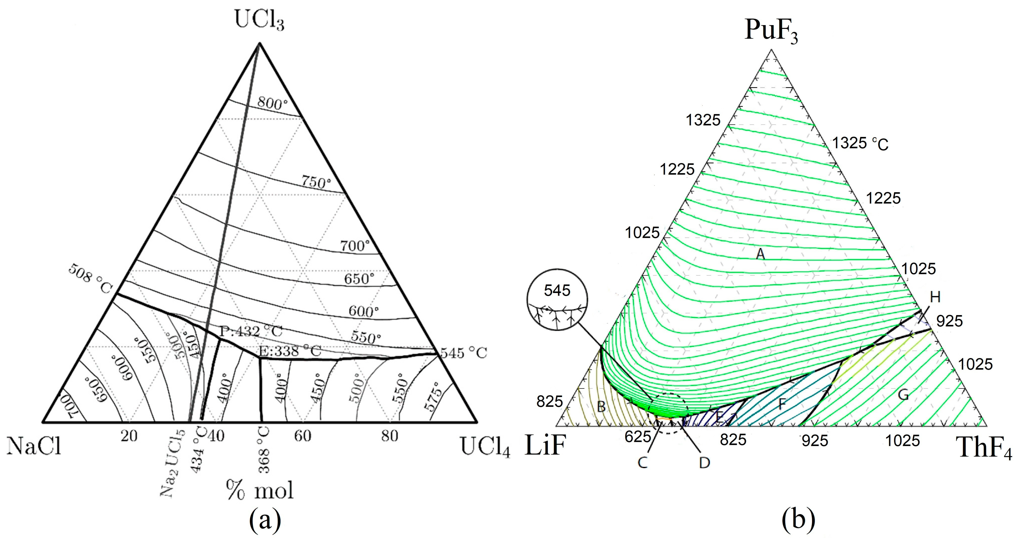
3.1.1. Melting Point
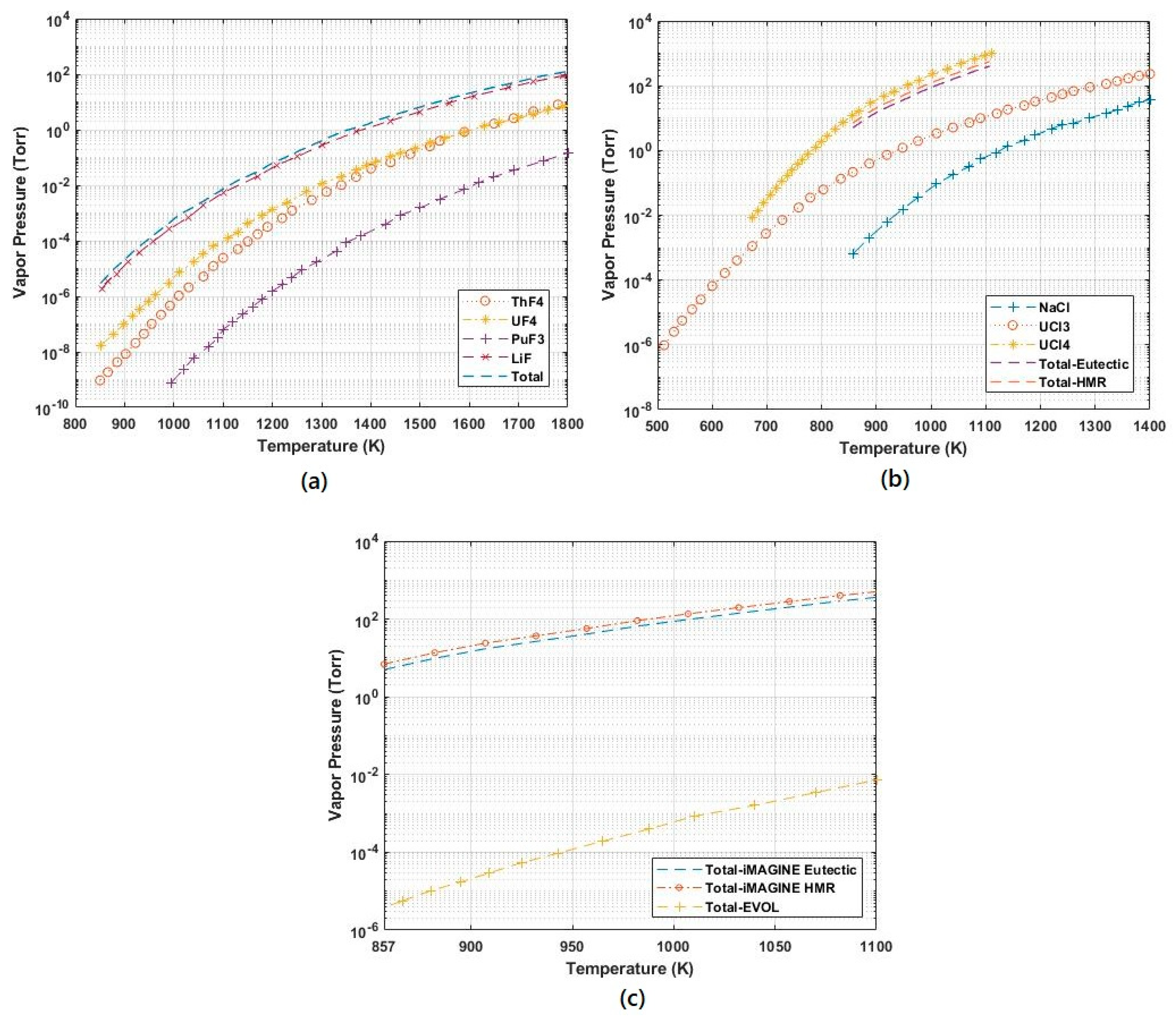
3.1.2. Boiling Point and Vapour Pressure
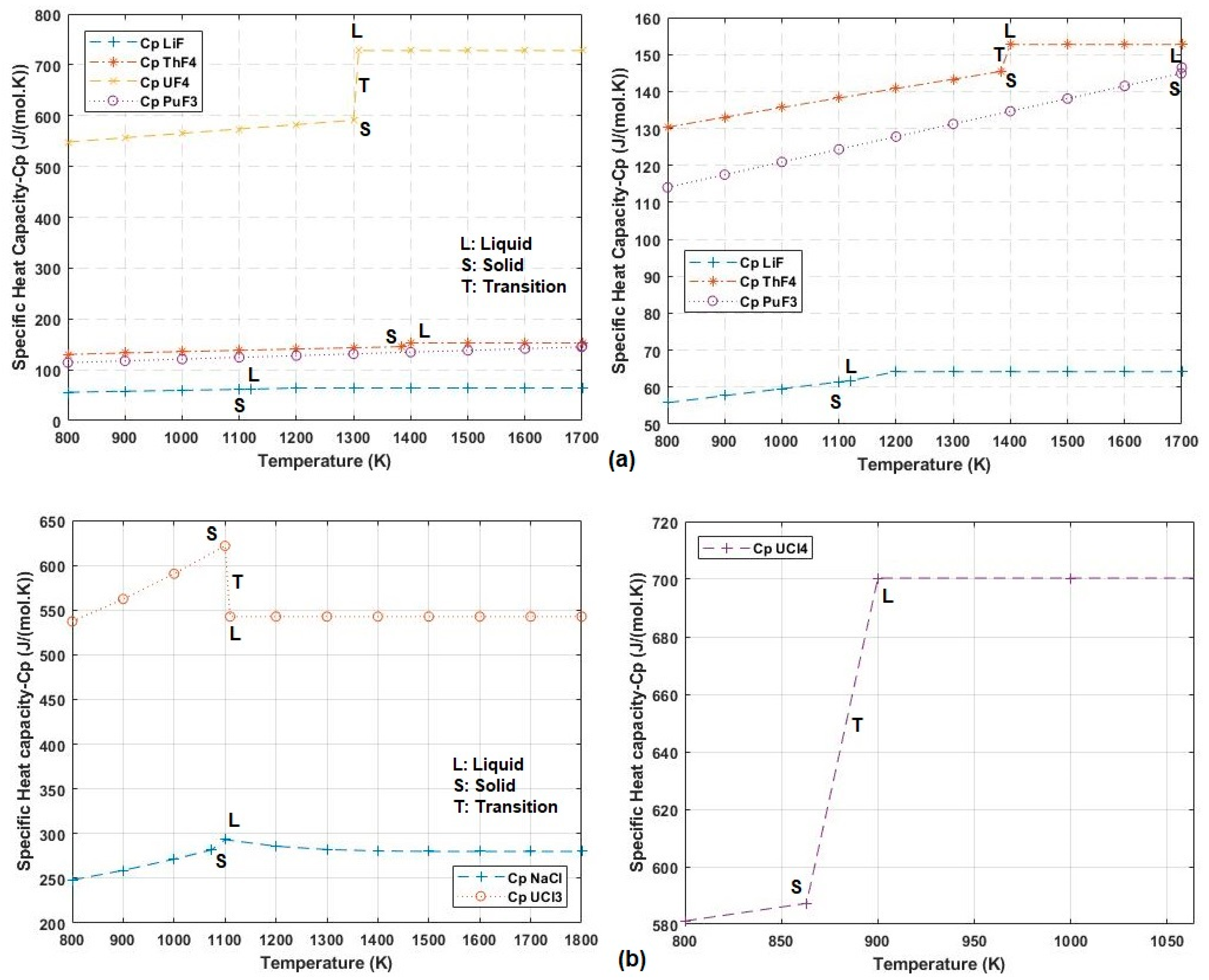
3.1.3. Specific Heat Capacity
3.1.4. Thermal Conductivity
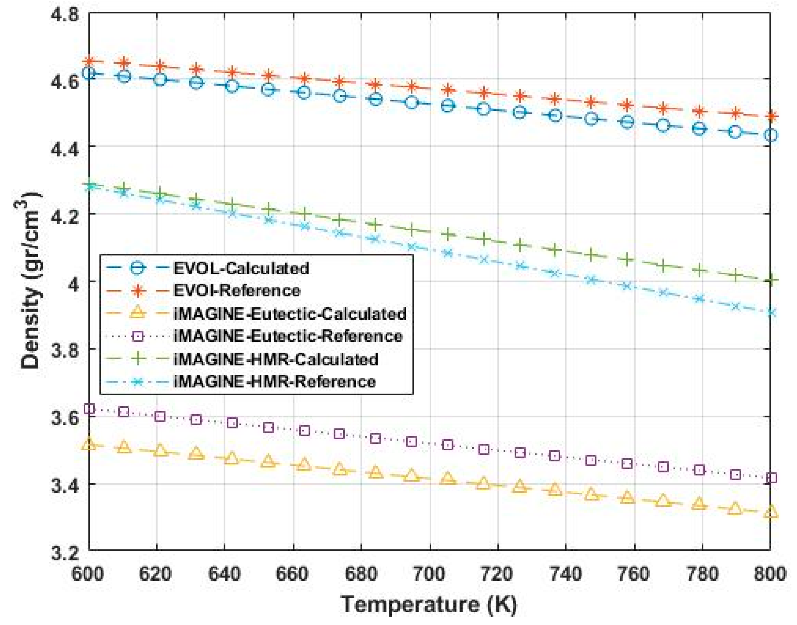
3.1.5. Density
3.2. Criticality Search
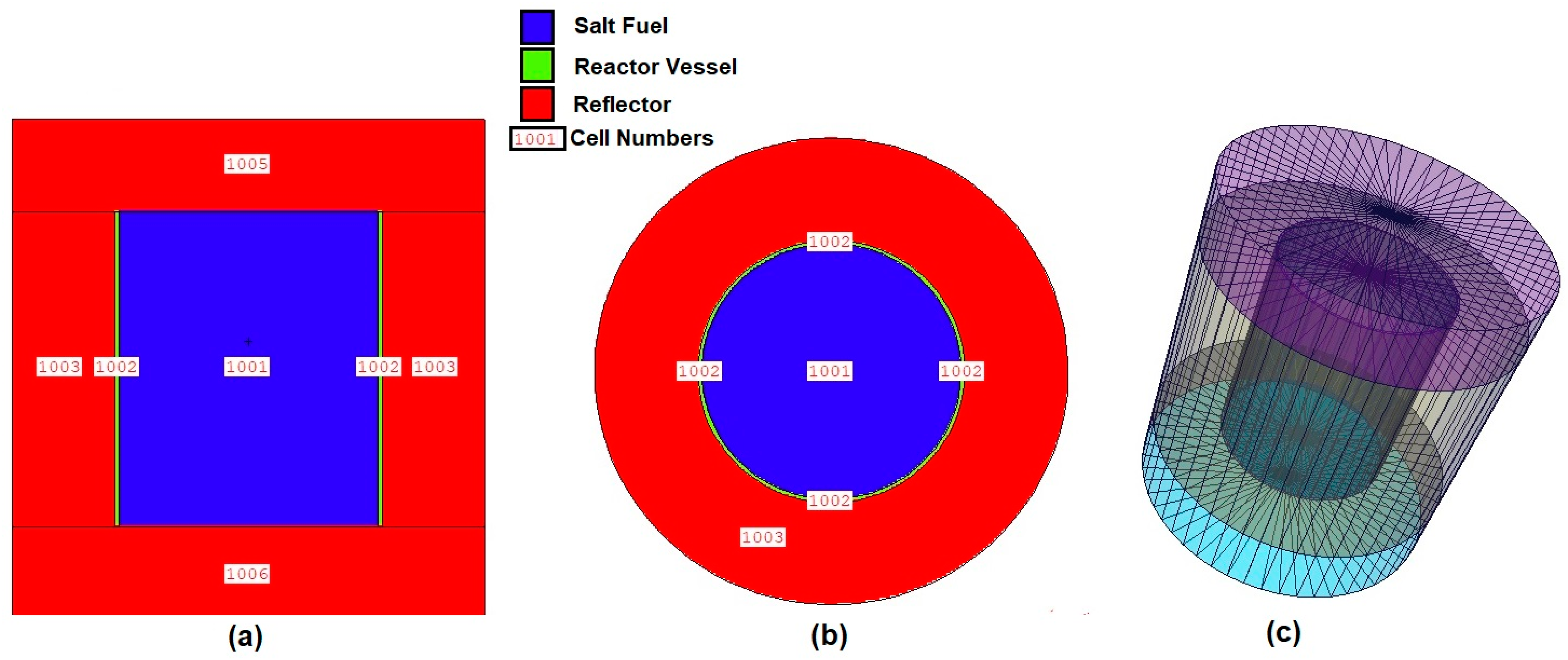
- The reactor core geometry needs to be considered cylinder, as results of the EVOL survey [11] and different geometries, such as cylinder, sphere etc., have been surveyed in both the iMAGINE and EVOL projects.
- The thermal-hydraulic design of MSRs can force the geometrical dimension of the reactor core, especially for the iMAGINE project, in which the main goal in the first step is to design a zero-power research reactor and remove heat by natural convection without having a specific heat transfer system, and thus, relying on leakage and low power. These criteria lead to having a vertical cylinder, which means, at the most, the diameter of the cylinder should be equal to or smaller than the cylinder height. These criteria come from the TH point of the natural convection source based on the density gradient in the reactor core (and can be connected by the Grashof (Gr) number).
- Excess reactivity of 300–600 pcm is usually considered for this type of reactor to have enough criticality margin during the reactor’s life cycle, although this value depends mainly on the burnup and core temperature history that will be studied in the next section of the article.
- With a smaller reactor core, less fuel and lower fuel costs occur.
4. Conclusions
Author Contributions
Funding
Data Availability Statement
Conflicts of Interest
References
- Pioro, I.L. Introduction: Generation IV International Forum. In Handbook of Generation IV Nuclear Reactors; Elsevier Ltd.: Amsterdam, The Netherlands, 2016. [Google Scholar] [CrossRef]
- Merk, B.; Litskevich, D.; Peakman, A.; Benkhad, M. IMAGINE—A Disruptive Change to Nuclear or How Can We Make More Out of the Existing Spent Nuclear Fuel and What Has to be Done to Make it Possible in the UK? Awt-Int. Z. Fuer Kernenerg. 2019, 64, 353–359. [Google Scholar]
- Merk, B.; Litskevich, D.; Whittle, K.R.; Bankhead, M.; Taylor, R.J.; Mathers, D. On a long term strategy for the success of nuclear power. Energies 2017, 10, 867. [Google Scholar] [CrossRef] [Green Version]
- IAEA-TECDOC-1696; Challenges Related to the Use of Liquid Metal and Molten Salt Coolants in Advanced Reactors. International Atomic Energy Agency: Vienna, Austria, 2013.
- Haubenreich, P.N.; Engel, J.R. Experience With the Molten-Salt Reactor Experiment. Nucl. Appl. Technol. 1970, 8, 118–136. [Google Scholar] [CrossRef]
- Fratoni, M.; Shen, D.; Ilas, G.; Powers, J. Molten Salt Reactor Experiment Benchmark Evaluation. Miskolc Math. Notes 2020, 21, 51–60. [Google Scholar]
- Prince, B.E.; Ball, S.J.; Engel, J.R.; Haubenreich, P.N.; Kerlin, T.W. Zero-Power Experiments on the Molten-Salt Reactor Experiment; Oak Ridge National Laboratory: Oak Ridge, TN, USA, 1968. [Google Scholar]
- Thoma, R. Phase Diagram of Nuclear Reactor Materials; Oak Ridge National Laboratory: Oak Ridge, TN, USA, 1959. [Google Scholar]
- US Atomic Energy Commission. An Evaluation of the Molten Salt Breeder Reactor; U.S. Government Printing Office: Washington, DC, USA, 1972.
- Smith, J.; Simmons, W.E. An Assessment of a 2500 MWe Molten Chloride Salt Fast Reactor; Atomic Energy Establishment: Winfrith, UK, 1974. [Google Scholar]
- EVOL (Project n°249696) Final Report. 2015. Available online: https://cordis.europa.eu/project/id/249696 (accessed on 10 June 2022).
- Final Report Summary—EVOL, CORDIS|European Commission [WWW Document]. 2013. Available online: https://cordis.europa.eu/project/id/249696/reporting (accessed on 30 June 2022).
- Ignatiev, V.; Feynberg, O.; Gnidoi, I.; Konakov, S.; Kormilitsyn, M.; Merzliakov, A.; Surenkov, A.; Uglov, V.; Zagnitko, A. MARS: Story on Molten Salt Actinide Recycler and Transmuter Development by Rosatom in Co-operation with Euratom; Nuclear Energy Agency of the OECD (NEA): Paris, France, 2015. [Google Scholar]
- Ignatiev, V.; Feynberg, O.; Gnidoi, I.; Merzlyakov, A.; Surenkov, A.; Uglov, V.; Zagnitko, A.; Subbotin, V.; Sannikov, I.; Toropov, A.; et al. Molten salt actinide recycler and transforming system without and with Th-U support: Fuel cycle flexibility and key material properties. Ann. Nucl. Energy 2014, 64, 408–420. [Google Scholar] [CrossRef]
- A Paradigm Shift in Reactor Safety with the Molten Salt Fast Reactor [WWW Document]. CORDIS EU Research Results. 2019. Available online: https://cordis.europa.eu/project/id/661891 (accessed on 10 June 2022).
- Faure, B.; Kooyman, T. A comparison of actinide halides for use in molten salt reactor fuels. Prog. Nucl. Energy 2022, 144, 104082. [Google Scholar] [CrossRef]
- Gakhar, R.; Phillips, W.C.; Cao, G.; Yoo, T.S.; Woods, M.E.; Fredrickson, G.L.; Karlsson, T. Molten Salt Fuels: Properties, Purification, and Corrosion Control. Encycl. Nucl. Energy 2021, 366–376. [Google Scholar] [CrossRef]
- Merk, B.; Litskevich, D.; Bankhead, M.; Taylor, R.J. An innovative way of thinking nuclear waste management—Neutron physics of a reactor directly operating on SNF. PLoS ONE 2017, 12, e0180703. [Google Scholar] [CrossRef] [Green Version]
- Merk, B.; Litskevich, D.; Gregg, R.; Mount, A.R. Demand driven salt clean-up in a molten salt fast reactor—Defining a priority list. PLoS ONE 2018, 13, e0192020. [Google Scholar] [CrossRef] [Green Version]
- Merk, B.; Detkina, A.; Atkinson, S.; Litskevich, D.; Cartland-Glover, G. Evaluation of the breeding performance of a NaCl-UCl-Based reactor system. Energies 2019, 12, 3853. [Google Scholar] [CrossRef] [Green Version]
- Merk, B.; Detkina, A.; Litskevich, D.; Atkinson, S.; Cartland-Glover, G. The interplay between breeding and thermal feedback in a molten chlorine fast reactor. Energies 2020, 13, 1609. [Google Scholar] [CrossRef]
- Merk, B.; Detkina, A.; Atkinson, S.; Litskevich, D.; Cartland-Glover, G. Evaluating reactivity control options for a chloride salt-based molten salt zero-power reactor. Appl. Sci. 2021, 11, 7447. [Google Scholar] [CrossRef]
- Merk, B.; Detkina, A.; Atkinson, S.; Litskevich, D.; Cartland-Glover, G. On the dimensions required for a molten salt zero power reactor operating on chloride salts. Appl. Sci. 2021, 11, 6673. [Google Scholar] [CrossRef]
- Merk, B.; Detkina, A.; Litskevich, D.; Drurdy, M.; Noori-Kalkhoran, O.; Cartland-Glover, G.; Petit, L.; Rolfo, S.; Elliot, J.P.; Mount, A.R. Defining the Challenges—Identifying the Key Poisoning Elements to Be Separated in a Future Integrated Molten Salt Fast Reactor Clean-Up System for iMAGINE. Appl. Sci. 2022, 12, 4124. [Google Scholar] [CrossRef]
- Pelowitz, D.B. Mcnpx User’ S Manual—Version 2.7.0; Los Alamos National Laboratory: Los Alamos, NM, USA, 2011. [Google Scholar]
- Chadwick, M.B.; Herman, M.; Obložinský, P.; Dunn, M.; Danon, Y.; Kahler, A.; Smith, D.; Pritychenko, B.; Arbanas, G.; Arcilla, R.; et al. ENDF/B-VII.1 nuclear data for science and technology: Cross sections, covariances, fission product yields and decay data. Nucl. Data Sheets 2011, 112, 2887–2996. [Google Scholar] [CrossRef]
- Katyshev, S.; Teslyuk, L. Ionic Melts in Nuclear Power. In Challenges and Solutions in the Russian Energy Sector; Springer: Berlin/Heidelberg, Germany, 2018; pp. 181–189. [Google Scholar]
- Capelli, E.; Beneš, O.; Colle, J.Y.; Konings, R.J.M. Determination of the thermodynamic activities of LiF and ThF4 in the LixTh1-xF4-3x liquid solution by Knudsen effusion mass spectrometry. Phys. Chem. Chem. Phys. 2015, 17, 30110–30118. [Google Scholar] [CrossRef] [Green Version]
- Baehr, H.D. Thermochemical properties of inorganic substances. Forsch. Im Ing. 1992, 58, 103. [Google Scholar] [CrossRef] [Green Version]
- Bradley, D. The Preparation and Properties of the Chlorides of Uranium, Plutonium, Thorium and of the Fission Product Chlorides; A.E.R.E. Harwell Rep. OE/b 2215; Atomic Energy Research Establishment: Harwell, UK, 1957. [Google Scholar]
- Ewing, C.T.; Stern, K.H. Equilibrium Vaporization Rates. J. Phys. Chem. 1974, 78, 1998–2005. [Google Scholar] [CrossRef]
- Fiock, E.F.; Rodebush, W.H. The vapor pressures and thermal properties of potassium and some alkali halides. J. Am. Chem. Soc. 1926, 48, 2522–2528. [Google Scholar] [CrossRef]
- Myers, P.D.; Goswami, D.Y. Thermal energy storage using chloride salts and their eutectics. Appl. Therm. Eng. 2016, 109, 889–900. [Google Scholar] [CrossRef] [Green Version]
- Parker, S.S.; Long, A.; Lhermitte, C.; Vogel, S.; Monreal, M.; Jackson, J.M. Thermophysical properties of liquid chlorides from 600 to 1600 K: Melt point, enthalpy of fusion, and volumetric expansion. J. Mol. Liq. 2022, 346, 118147. [Google Scholar] [CrossRef]
- Price, J.C.; Mariani, R.D. Synthesis of Uranium Trichloride for the Pyrometallurgical Processing of Used Nuclear Fuel; INL/CON-10-20111; Idaho National Lab: Idaho Falls, ID, USA, 2011.
- Williams, D.F.; Toth, L.M.; Clarno, K.T. Assessment of Candidate Molten Salt Coolants for the Advanced High-Temperature Reactor (AHTR); Ornl/Tm-2006/69; National Technical Information Service: Springfield, VA, USA, 2006.
- Kopp, H. Investigation of the Specific Heat of Solid Bosies; Royal Society: London, UK, 1864. [Google Scholar]
- Leitner, J.; Voňka, P.; Sedmidubský, D.; Svoboda, P. Application of Neumann-Kopp rule for the estimation of heat capacity of mixed oxides. Thermochim. Acta 2010, 497, 7–13. [Google Scholar] [CrossRef]
- Touloukian, Y.; Powell, R.; Ho, C.; Klemens, P. Thermal Conductivity-Nonmetallic Solids. 1971. Available online: https://www.piping-designer.com/index.php/properties/878-tables/2728-thermal-conductivity-of-non-metallic-solids (accessed on 5 July 2022).
- Capelli, E.; Konings, R.J.M. Halides of the Actinides and Fission Products Relevant for Molten Salt Reactors. In Comprehensive Nuclear Materials, 2nd ed.; Elsevier Ltd.: Amsterdam, The Netherlands, 2020. [Google Scholar] [CrossRef]
- Morss, L.R.; Edelstein, N.; Fuger, J.; Katz, J.J. Chemistry of Actinide and Transactinide Elements, 4th ed.; Springer: Berlin/Heidelberg, Germany, 2010. [Google Scholar]
- Haupin, W. Hot wire method for rapid determination of thermal conductivity. Am. Ceram. Soc. Bull. 1960, 39, 139–141. [Google Scholar]
- Cornwell, K. The thermal conductivity of molten salts. Appl. Phys. 1970, 4, 441–445. [Google Scholar] [CrossRef]
- Gheribi, A.E.; Torres, J.A.; Chartrand, P. Recommended values for the thermal conductivity of molten salts between the melting and boiling points. Sol. Energy Mater. Sol. Cells 2014, 126, 11–25. [Google Scholar] [CrossRef]
- Ignatiev, V.; Merzlyakov, A. Transport Properties of Molten-Salt Reactor Fuel Mixtures: The Case Of Na, Li, Be/F And Li, Be, Th/F Salts. In Actinide and Fission Product Partitioning and Transmutation; Nuclear Energy Agency of the OECD (NEA): Paris, France, 2003; pp. 581–590. [Google Scholar]
- Rama Rao, M. Thermal Conductivity of Liquids. Phys. Rev. 1940, 59, 212. [Google Scholar]
- Grimes, W.R. Reactor Chemistry Division, Annual Progress Report for Period Ending December 31, 1965; Oak Ridge National Laboratory: Oak Ridge, TN, USA, 1965. [Google Scholar] [CrossRef]
- Grimes, W.R. Annual Progress Report for Period Ending January 31, 1962; Oak Ridge National Laboratory: Oak Ridge, TN, USA, 1962. [Google Scholar]
- Desyatnik, V.; Katyshev, S. Volumetric and surface properties of the NaCl-UCl3-UCl4 melts. Zhurnal Fiz. Khimii 1980, 54, 1606–1610. [Google Scholar]


| Reactor Type | Salt Fuel Composition | Reactor Vessel | Reflector |
|---|---|---|---|
| iMAGINE-Eutectic 1 | NaCl-UCl3-UCl4 (42.5-17-40.5 mol%) | Stainless Steel | NaCl |
| iMAGINE-HMR 2 | NaCl-UCl3-UCl4 (20-23.65-56.35 mol%) | Stainless Steel | NaCl |
| EVOL | LiF-ThF4-UF4-PuF3 (78.6-12.9-3.5-5 mol%) | Ni-based alloy | Ni-based alloy |
| Material | Cr | Mn | Fe | Ni | W | Mo | Ti |
|---|---|---|---|---|---|---|---|
| Stainless Steel | 3.54 × 10⁻³ | 8.74 × 10⁻³ | 9.80 × 10⁻¹ | 7.60 × 10⁻³ | 0 | 0 | 0 |
| Ni alloy | 8.01 × 10⁻² | 2.57 × 10⁻³ | 6.32 × 10⁻³ | 7.94 × 10⁻¹ | 9.98 × 10⁻¹ | 7.36 × 10⁻³ | 2.95 × 10⁻³ |
| Material | C | Si | Al | B | P | S | |
| Stainless Steel | 0 | 0 | 0 | 0 | 0 | 0 | |
| Ni alloy | 2.94 × 10⁻³ | 2.52 × 10⁻³ | 5.20 × 10⁻⁴ | 3.30 × 10⁻⁴ | 2.30 × 10⁻⁴ | 4.00 × 10⁻⁵ |
| Category | Constraint |
|---|---|
| Physical | Low melting point |
| High boiling temperature | |
| Low vapour pressure | |
| Chemical | Solubility of fissile and fertile material |
| Less production of hardly manageable isotopes | |
| Less clean-up of the fuel salt during reactor’s life cycle | |
| Less corrosion potential | |
| Thermal-hydraulic | High Specific heat capacity and thermal conductivity |
| Neutronic | Neutron transparency |
| Irradiation resistance |
| LiF | ThF4 | PuF3 | Temperature (K)/Equilibria Type | Crystal Phase in Equilibrium |
|---|---|---|---|---|
| 0.692 | 0.283 | 0.025 | 863/Quasi-Peritectic | (Th,Pu) Fx (s.s.), LiTh2F9, LiThF5 |
| 0.724 | 0.253 | 0.023 | 822/Eutectic | (Th,Pu) Fx (s.s.), LiThF5, Li3ThF7 |
| Salt Fuel | Density Function (600–800 °C; ~873–1073 K) (gr/cm3) |
|---|---|
| EVOL | [11] |
| iMAGINE-Eutectic | [21,49] |
| iMAGINE-HMR | [21,49] |
| Type | V *- Height (cm) | V-IR/ID (cm) | V-ER/ED (cm) | Ref-ER (cm) | V-Volume (cm3) | U235 (%) | Fuel T ** (K) | K eff | St Dev (%) |
|---|---|---|---|---|---|---|---|---|---|
| Eutectic | 170 | 65/130 | 67/134 | 122 | 2.26 | 35 | 980 | 0.98021 | 0.00006 |
| Eutectic | 170 | 67/134 | 69/138 | 124 | 2.40 | 35 | 980 | 0.99286 | 0.00006 |
| Eutectic | 170 | 69/138 | 71/142 | 126 | 2.54 | 35 | 980 | 1.00492 | 0.00004 |
| Eutectic | 170 | 71/142 | 73/146 | 128 | 2.70 | 35 | 980 | 1.01658 | 0.00006 |
| Eutectic | 170 | 73/146 | 75/150 | 130 | 2.85 | 35 | 980 | 1.02772 | 0.00007 |
| Eutectic | 170 | 75/150 | 77/154 | 132 | 3.00 | 35 | 980 | 1.03847 | 0.00006 |
| Type | V *- Height (cm) | V-IR/ID (cm) | V-ER/ED (cm) | Ref-ER (cm) | V-Volume (cm3) | U235 (%) | Fuel T ** (K) | K eff | St Dev (%) |
|---|---|---|---|---|---|---|---|---|---|
| HMR | 170 | 63/126 | 65/130 | 120 | 2.12 | 35 | 980 | 1.04152 | 0.00007 |
| HMR | 170 | 61/122 | 63/126 | 118 | 1.99 | 35 | 980 | 1.02787 | 0.00005 |
| HMR | 170 | 59/118 | 61/122 | 116 | 1.86 | 35 | 980 | 1.01353 | 0.00006 |
| HMR | 170 | 58/116 | 60/120 | 115 | 1.80 | 35 | 980 | 1.00611 | 0.00005 |
| HMR | 170 | 57/114 | 59/118 | 114 | 1.73 | 35 | 980 | 0.99863 | 0.00007 |
| HMR | 170 | 55/110 | 57/114 | 112 | 1.61 | 35 | 980 | 0.95521 | 0.00007 |
| Type | V *- Height (cm) | V-IR/ID (cm) | V-ER/ED (cm) | Ref-ER (cm) | V-Volume (cm3) | U235 (%) | Fuel T ** (K) | K eff | St Dev (%) |
|---|---|---|---|---|---|---|---|---|---|
| EVOL | 170 | 61/122 | 63/126 | 118 | 1.99 | 35 | 980 | 1.05475 | 0.00007 |
| EVOL | 170 | 59/118 | 61/122 | 116 | 1.86 | 35 | 980 | 1.04632 | 0.00007 |
| EVOL | 170 | 57/114 | 59/118 | 114 | 1.73 | 35 | 980 | 1.03732 | 0.00007 |
| EVOL | 170 | 55/110 | 57/114 | 112 | 1.61 | 35 | 980 | 1.02764 | 0.00007 |
| EVOL | 170 | 53/106 | 55/110 | 110 | 1.50 | 35 | 980 | 1.01708 | 0.00006 |
| EVOL | 170 | 51/102 | 53/106 | 108 | 1.39 | 35 | 980 | 1.00551 | 0.00006 |
| Type | V *- Height (cm) | V-IR/ID (cm) | V-ER/ED (cm) | Ref-ER (cm) | V-Volume (cm3) | U235 (%) | Fuel T ** (K) | K eff | St Dev (%) |
|---|---|---|---|---|---|---|---|---|---|
| iMAGINE-Eutectic | 170 | 69/138 | 71/142 | 126 | 2.54 | 35 | 980 | 1.00492 | 0.00004 |
| iMAGINE-HMR | 170 | 58/116 | 60/120 | 115 | 1.80 | 35 | 980 | 1.00611 | 0.00005 |
| EVOL | 170 | 51/102 | 53/106 | 108 | 1.39 | 35 | 980 | 1.00551 | 0.00006 |
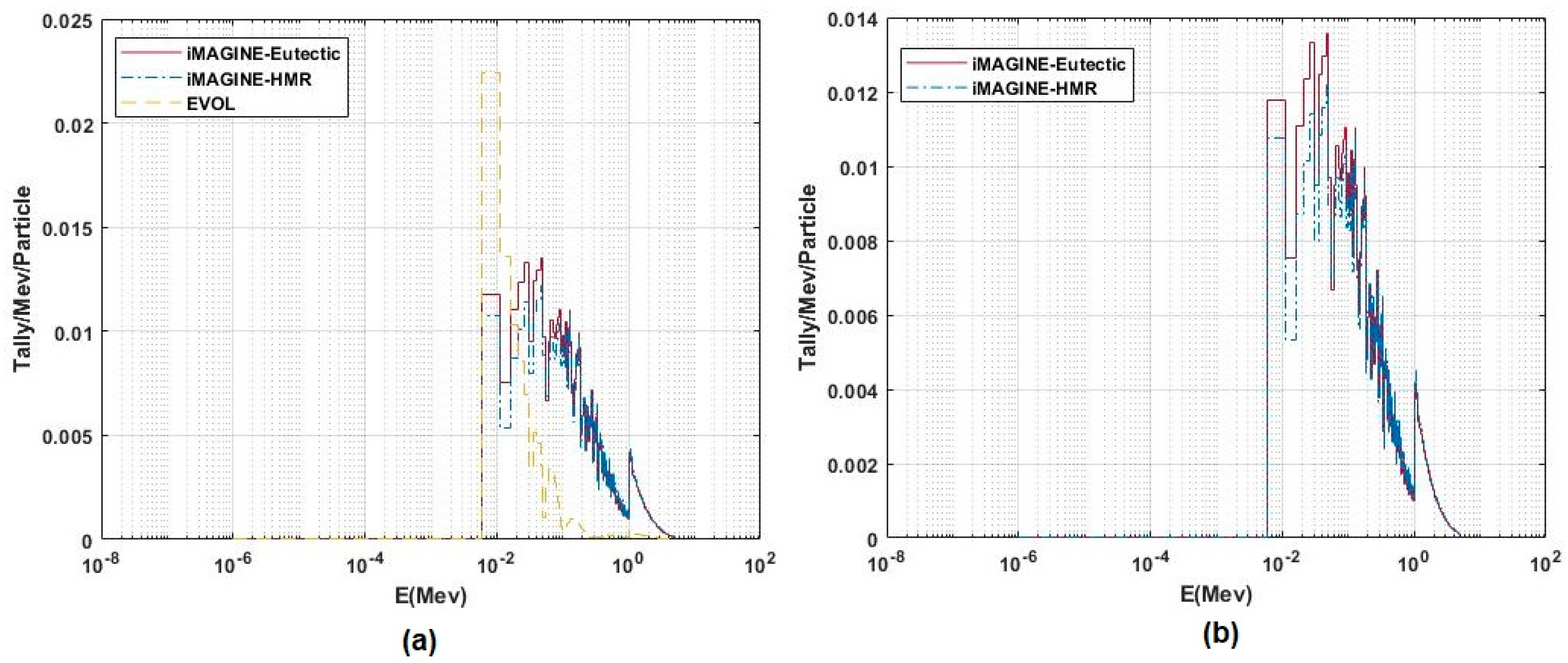
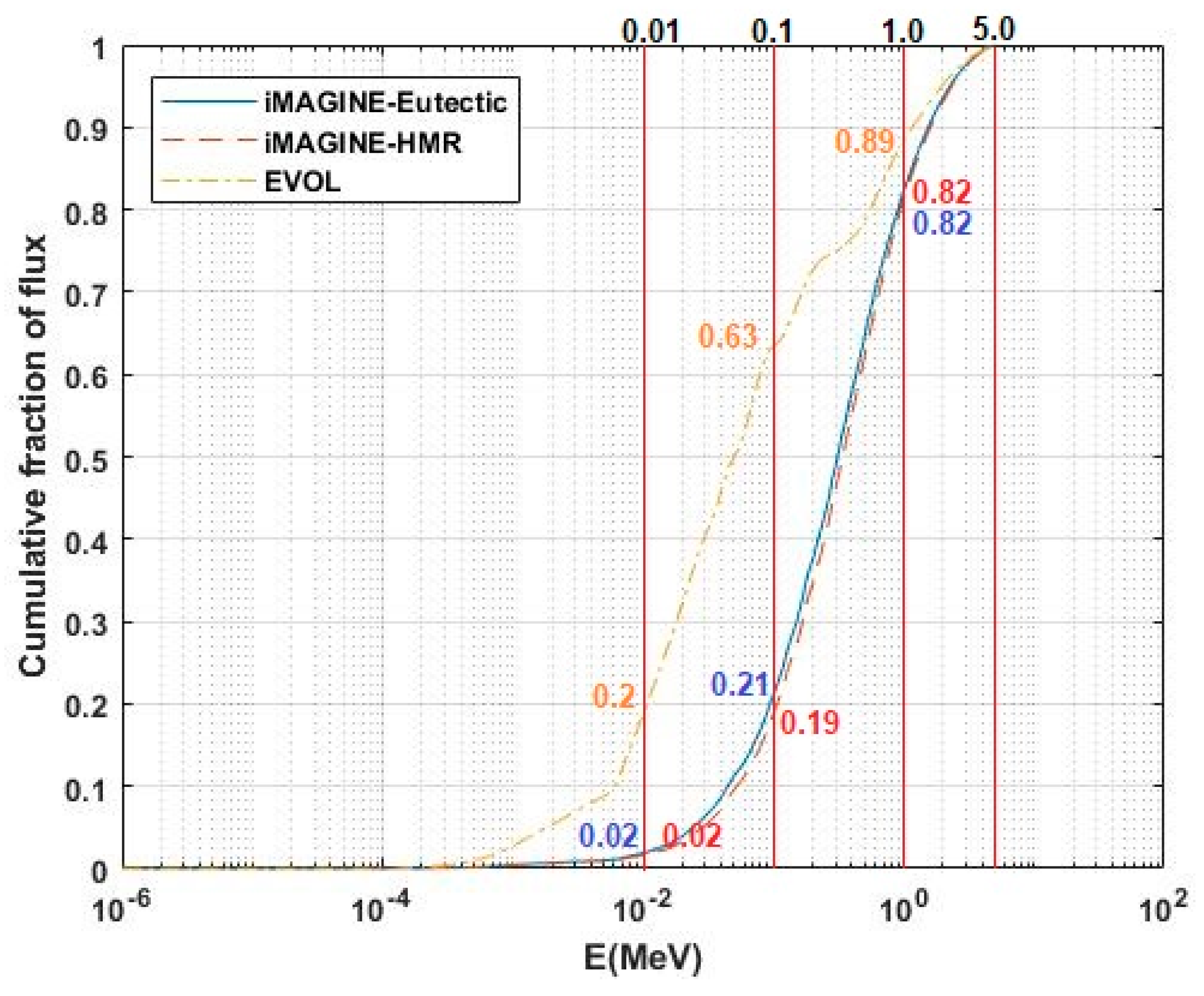
| Fuel Salt System | E < 0.01 MeV | 0.01 < E < 0.1 | 0.1 < E < 1.0 | E > 1.0 |
|---|---|---|---|---|
| EVOL (%) | 20 | 43 | 26 | 11 |
| iMAGINE-Eutectic (%) | 2 | 19 | 60 | 19 |
| iMAGINE-HMR (%) | 2 | 17 | 63 | 18 |
| Parameter/Salt Fuel System | EVOL | iMAGINE-Eutectic | iMAGINE-HMR | |
|---|---|---|---|---|
| Thermophysical properties | Melting point (K) Figure 2 | Eutectic:822 K (Composition: 72.4-25.3-2.3 mol%) Peritectic: 863 K (Composition: 69.2-28.3-2.5 mol%) Higher melting point and Lower Peritectic/Eutectic gradient | Eutectic: 611 K (HMR~735 K) (Composition: 42.5-17-40.5 mol%) Peritectic: 705 K (Composition: 49.0-21.5-29.5 mol%) Lower melting point and higher Peritectic/Eutectic gradient | |
| Vapour pressure/Boiling point (K) Figure 3 | 0.07 Pa at 1000 K Lowest vapour pressure/Highest boiling point | 88.0 Pa at 1000 K High vapour pressure/Low boiling point | 122.4 Pa at 1000 K Highest vapour pressure/Lowest boiling point | |
| Specific heat capacity (J/(mol·K)) Figure 4 | ~87.9 at melting point Lowest heat capacity | ~494.9 at melting point Higher heat capacity | ~579.0 at melting point Highest heat capacity | |
| Thermal conductivity (Watt/(m·K)) Equation (4) | ~0.9078 constant Higher Thermal Conductivity | ~0.3163 constant Lower Thermal Conductivity | ~0.2611 constant Lowest Thermal Conductivity | |
| Density (gr/cm3) Figure 5 | 5.1720 − 0.9223 × 10⁻³ T * Highest Density vs. temperature | 4.1224 − 1.0117 × 10⁻³ T Lowest Density vs. temperature | 5.1487 − 1.4316 × 10⁻³ T Lower Density vs. temperature | |
| Neutronic design | Criticality Volume (cm3) Table 9 | 1.39 Smallest critical size | 2.54 Largest critical size | 1.80 Large critical size |
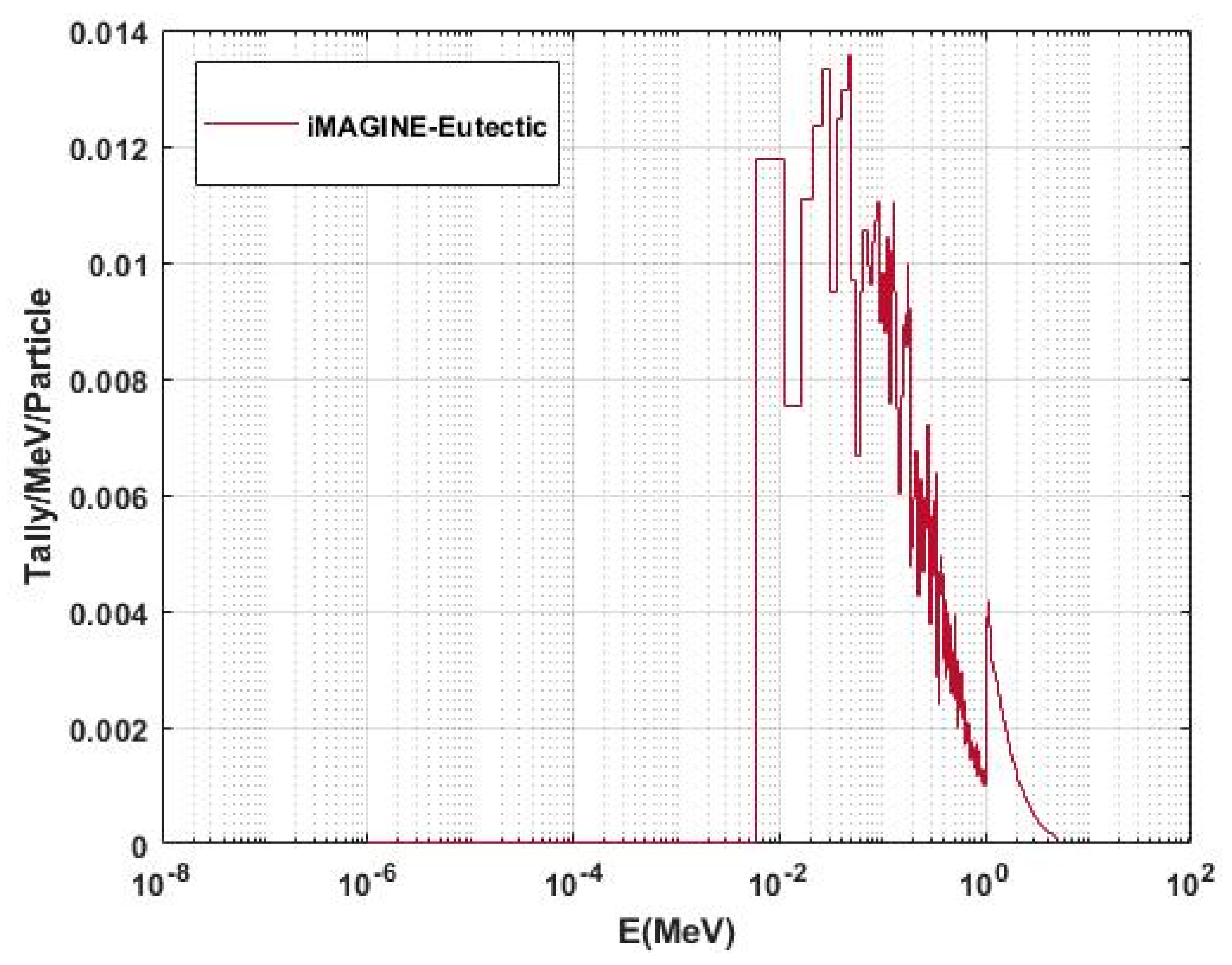
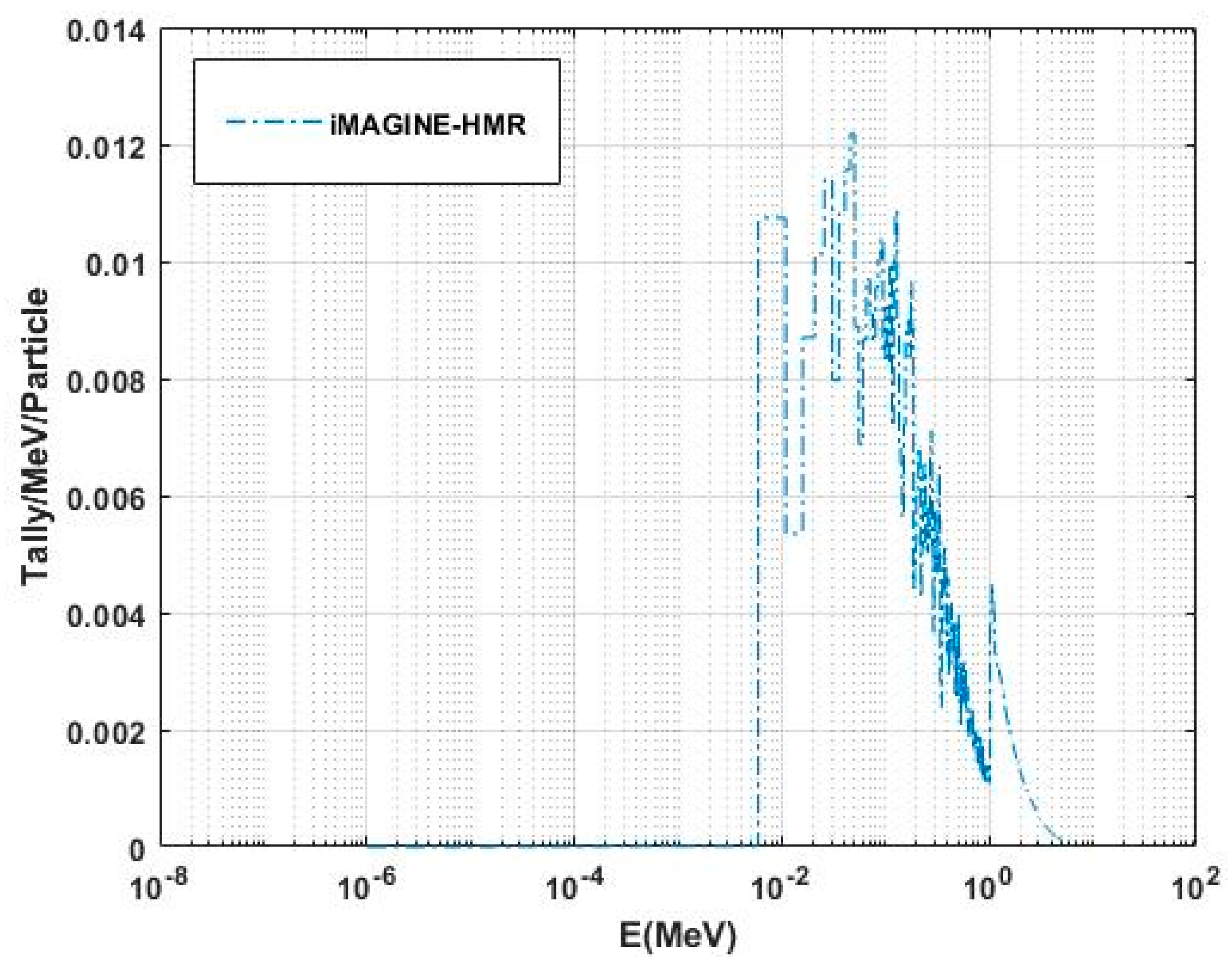
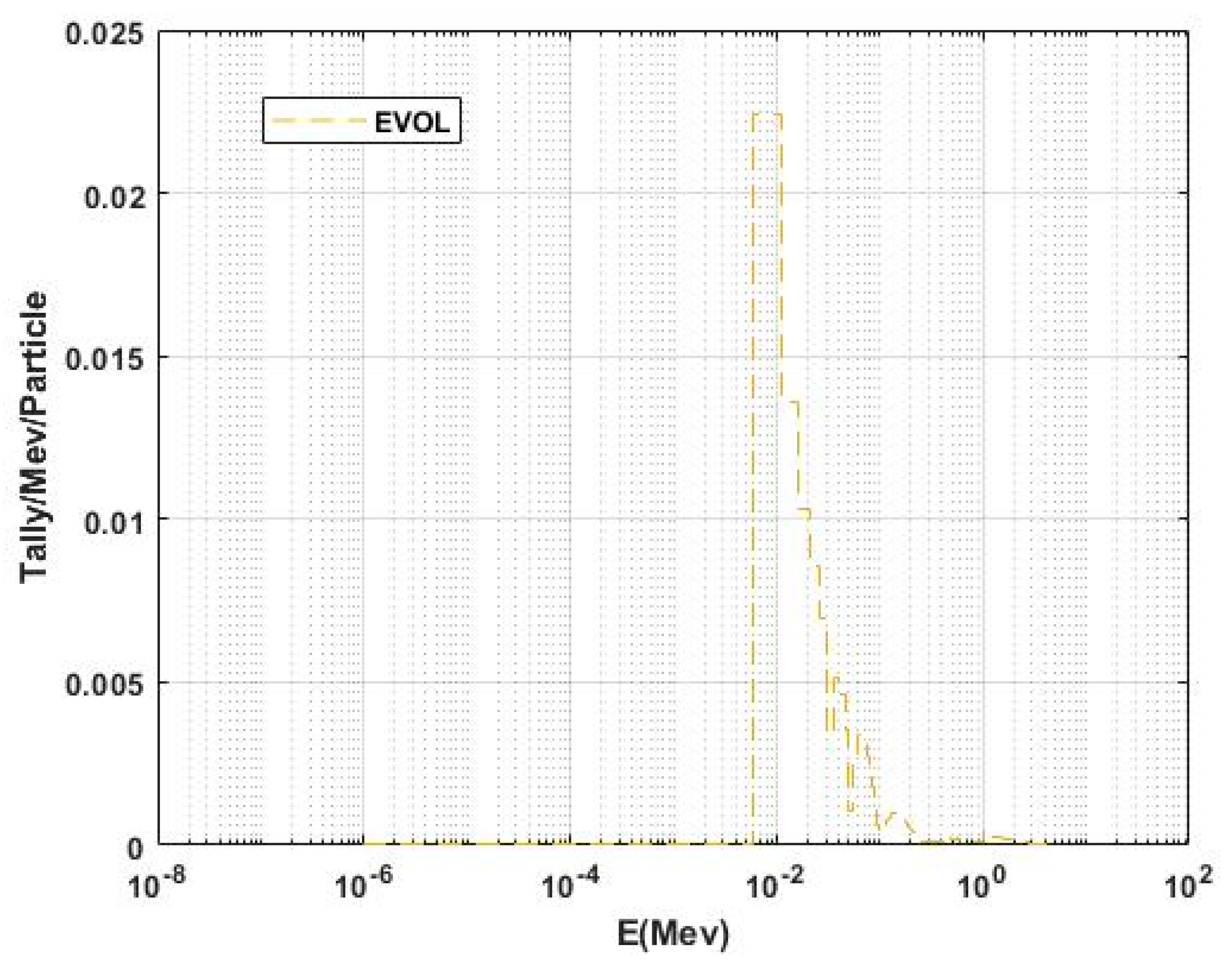
| Neutron flux-energy spectrum Figure 9 and Table 10 | Softer neutron flux-energy spectrum | Hardest neutron flux-energy spectrum | Hard neutron flux-energy spectrum | |
Publisher’s Note: MDPI stays neutral with regard to jurisdictional claims in published maps and institutional affiliations. |
© 2022 by the authors. Licensee MDPI, Basel, Switzerland. This article is an open access article distributed under the terms and conditions of the Creative Commons Attribution (CC BY) license (https://creativecommons.org/licenses/by/4.0/).
Share and Cite
Noori-kalkhoran, O.; Litskevich, D.; Detkina, A.; Jain, L.; Cartland-Glover, G.; Merk, B. On the Employment of a Chloride or Fluoride Salt Fuel System in Advanced Molten Salt Reactors, Part 1: Thermophysical Properties and Core Criticality. Energies 2022, 15, 8865. https://doi.org/10.3390/en15238865
Noori-kalkhoran O, Litskevich D, Detkina A, Jain L, Cartland-Glover G, Merk B. On the Employment of a Chloride or Fluoride Salt Fuel System in Advanced Molten Salt Reactors, Part 1: Thermophysical Properties and Core Criticality. Energies. 2022; 15(23):8865. https://doi.org/10.3390/en15238865
Chicago/Turabian StyleNoori-kalkhoran, Omid, Dzianis Litskevich, Anna Detkina, Lakshay Jain, Gregory Cartland-Glover, and Bruno Merk. 2022. "On the Employment of a Chloride or Fluoride Salt Fuel System in Advanced Molten Salt Reactors, Part 1: Thermophysical Properties and Core Criticality" Energies 15, no. 23: 8865. https://doi.org/10.3390/en15238865