Article

DEMO Divertor Cassette and Plasma facing Unit in Vessel Loss-of-Coolant Accident

by
Danilo Nicola Dongiovanni
1,*,
Matteo D’Onorio
2,
Gianfranco Caruso
2,
Tonio Pinna
1 and
Maria Teresa Porfiri
1
1
ENEA, C.R. Frascati, FSN Department, Via Enrico Fermi, 45, 00044 Frascati, Italy
2
Department of Astronautical Electrical and Energy Engineering (DIAEE), Sapienza University of Rome, C.so Vittorio Emanuele II 244, 00186 Rome, Italy
*
Author to whom correspondence should be addressed.
Energies 2022, 15(23), 8879; https://doi.org/10.3390/en15238879
Submission received: 14 September 2022 / Revised: 27 October 2022 / Accepted: 14 November 2022 / Published: 24 November 2022
(This article belongs to the Section B4: Nuclear Energy)

Abstract

:
As part of the pre-conceptual design activities for the European DEMOnstration plant, a carefully selected set of safety analyses have been performed to assess plant integrated performance and the capability to achieve expected targets while keeping it in a safe operation domain. The DEMO divertor is the in-vessel component in charge of exhausting the major part of the plasma ions’ thermal power in a region far from the plasma core to control plasma pollution. The divertor system accomplishes this goal by means of assemblies of cassette and target plasma facing units modules, respectively cooled with two independentheat-transfer systems. A deterministic assessment of a divertor in-vessel Loss-of-Coolant Accident is here considered. Both Design Basis Accident case simulating the rupture of an in-vessel pipe for the divertor cassette cooling loop, and a Design Extension Conditions accident case considering the additional rupture of an independent divertor target cooling loop are assessed. The plant response to such accidents is investigated, a comparison of the transient evolution in the two cases is provided, and design robustness with respect to safety objectives is discussed.

1. Introduction

Demonstrating the technological feasibility of the energy production from nuclear fusion reactions is the goal of the European DEMOnstration plant, expected to be operational by the mid-40ies of the current century [1]. European DEMO is a tokamak-based plasma magnetic confinement concept plant, which recently achieved the pre-conceptual design phase [2].
The divertor is a relevant system including components located inside the vacuum vessel of the tokamak mainly devoted to providing an exhaust removal function for reaction ashes. The divertor system [3] is composed of assemblies of cassette and target modules located inside the tokamak reaction chamber, i.e., vacuum vessel (VV), cooled by two independent heat-transfer-systems (HTSs).
A relevant part of the design activities is the early assessment of the plant with respect to its safety objectives to highlight possible showstoppers or provide feedback on design parameters to always be within a safe domain. This feedback is expected from the investigation of postulated accidental events under the so-called Design-Basis Accidents (DBA) category. At the same time, plant robustness, available safety margins, and the absence of cliff-edge effects are assessed by means of less likely events with more severe consequences falling under the Design Extension Conditions (DECs)/Beyond Design-Basis Accident (BDBA) category [4]. In particular, DECs are those conditions induced by sequences caused by multiple failures, which have a frequency of occurrence that cannot be neglected and, in some cases, are comparable with the frequency of some DBAs. The considered case falls within this definition as an accident scenario that includes combinations of initiating events.
The proposed deterministic safety analysis postulates an event and assesses the capability of the plant to manage the consequences with impact on workers, the public and the environment within the established safety objective limits. Accident consequences on plant Systems Structures and Components (SSCs) are investigated by means of the MELCOR severe accident simulation code [5,6] both for tokamak and other fusion-related facilities [7], including a sensitivity analysis in support of design safety [8]. In particular, the preservation of the radioactive inventory confinement function [9,10] allocated on VV, its extensions, and the surrounding building barriers is verified. Among the previous assessments of accidental events concerning the in-vessel DEMO systems, we recall: the divertor plasma-facing unit (PFU) in-VV LOCA and Loss-of-Flow Accident (LOFA) analyzed in [11,12] and the in-VV or In-BOX Loss-of-coolant Accidents (LOCA) accidents in Breeding Blanket systems [13,14,15,16].
Present work focuses on investigating the consequences of two in-vessel LOCA accident events: (i) a Design-Basis Accident (DBA) divertor cassette in-VV LOCA originating from a breach of the divertor cassette pipe and (ii) and a less likely case considering the additional breach of the divertor target cooling loop pipe co-occurring with the first accident. Note that divertor cassette and target heat-transfer systems (HTS) loops are independent in the current design, hence with an accordingly lower co-occurring failure frequency.
The impact on the first confinement barriers, i.e., vacuum vessel and related overpressure mitigation systems and building confinement barriers, is investigated for both accidents, and related transients patterns are compared.

2. Materials and Methods

2.1. DEMO Divertor In-Vessel Component and Heat-Transfer System Description

The main function of the divertor is to extract the power conducted in the scrape-off layer (SOL) whilst maintaining plasma purity. As the main interface component between the plasma and the components material, it tolerates high heat loads while providing neutron shielding for the vacuum vessel (VV) and magnet coils, near the divertor region. Below is an extract of the divertor in-vessel component functional breakdown structure (FBS) [17].
  • To exhaust ion particles (alfa, D, T, impurities) thermal power
    • Provide heat sink for absorbed power
      • To route coolant to divertor in order to re-exhaust thermal power
      • To provide heat transfer between plasma-facing components (PFCs) and coolant
  • Reduce plasma pollution by controlling impurity density in plasma
      • To avoid impurities (ejected from the wall or coming from plasma) entering the plasma core
      • To allow for impurity neutrals extraction (permit Helium and other neutrals extraction by pumping system)
The divertor system exploits two main modular sub-systems to accomplish the mentioned functions: divertor cassette [18] (Figure 1a) and divertor target [19] (Figure 1b). Each cassette supports two vertical plasma-facing units, one inboard and one outboard, intercepting the main part of the particle loads from the plasma.
The divertor cassette module is composed of a Eurofer [20] structure anchored to the VV (Figure 2a), with a liner and two reflector plates (Figure 2b) providing a shielding function. Cooling water enters the cassette body from a first volume, here tagged as Cassette Body-A (CB-A) (red volume in Figure 2c), then enters the liner and reflector plates formed by multiple layers of pipes and finally re-enters a second volume, Cassette Body-B (CB-B) (green volume in Figure 2c), before exiting the VV from the outlet feeding pipes.
The divertor target modules (Figure 3a) basic unit is the plasma facing unit (PFU) (Figure 3c) aggregated in arrays (Figure 3b) on the inner and outer sides of the vacuum vessel, respectively 31 in the inner vertical target (IVT) and 43 in the outer vertical target (OVT). The feeding pipes (Figure 3a) distribute coolant to the IVT and OVT in parallel before being re-collected and sent to the outlet feeding pipe. Each PFU is constituted by a CuCrZr pipe with 12-mm of inner diameter and a 17-mm outer diameter, surrounded by a full tungsten tile of 23 × 28 mm in section (Figure 3d).
The divertor cassette and divertor target module assembly (Figure 4a) is replicated in 3 segments for each of the 16 DEMO sectors, resulting in 48 units of each.
Divertor target and cassette modules are water-cooled by means of separate heat-transfer systems (HTSs) because of the different temperature requirements of the materials (Eurofer implying a minimum temperature of 180 °C for cassette coolant).
In turn, the PFU and cassette HTS loops are further split into 2 separate loops each (Figure 4b), serving 8 out of the 16 DEMO sectors. Each HTS loop includes a pressurizer (PRZ), a heat exchanger (HX), a pump, hot and cold leg pipes, distributor and collector half rings, and feeding and collecting pipes serving the considered inVV 24 divertor cassette/target units from the related 8 DEMO sectors considered. The cassette and PFU HTS loops nominal operating conditions summary data are provided in Table 1.
Note that despite being independent HTS loops, given the system’s layout and assembly, a common cause for their failure cannot be excluded. In fact, cassette and vertical targets are indeed thermally coupled, and the cassette acts as a mechanical support for vertical targets units and related cooling pipes (Figure 1c).

2.2. Accident Specification for the Considered Cases

A set of postulated initiating events (PIEs) have been identified for the DEMO in [21], including for divertor system in/ex-vacuum vessel (VV) Loss-of-Coolant Accidents and Loss-of-Flow Accidents. The present work investigates the consequences of an in-VV LOCA originating from a divertor cassette loop breach and the additional impact in terms of VV pressurization when considering the contextual failure of both the cassette and PFU. Note that the PFU HTS loop is independent from the DIV cassette loop in the considered baseline design. The PIE events to occur are:
PIE1. In-vessel LOCA in the DIV primary cooling circuitfor the cassette module.
PIE2. In-vessel LOCA in the DIV primary cooling circuit for the cassette module and target PFU loop.
The possible sequence for the identified PIEs starts with a guillotine double-end break in one divertor cassette feeding cooling pipe (break area of 0.01162 m2). The LOCA is supposed to occur at the inlet of the cassette (both in PIE1 and PIE2) and in the related divertor target PFU (area of 0.0286 m2) feeding cooling pipe (in the PIE2 case only).
Fusion power is terminated within 3 s by an unmitigated disruption depositing about 22 MJ within 10 ms on a 1-m2 tungsten tile PFU of an outer vertical target (OVT), different from the one involved in the PIE. When case-related PFU CuCrZr pipes (inner Cu layer considered) reach the melting temperature point (1083 °C), pipe failure is assumed, resulting in an increased blow-down.
Water coolant released inside the VV vaporizes and pressurizes the VV until set-points are possibly reached to open the lines connecting vacuum vessels to the vacuum vessel pressure suppression system (VVPSS). Bleed lines open towards a VVPSS-A expansion tank when a 0.9 bara pressure set-point is reached. If VV pressures reach 1.5 bara, a rupture disk (RD) opens towards a VVPSS (W) set of tanks. In such a case, the coolant and radioactive inventories (tritium, dust, and activated corrosion products (ACPs)) will be mobilized towards the VVPSS. The VVPSS system model is derived from [22].
Thirty-two hours of off-loss of site power after the initiating event is considered. After the coolant inventory is lost, the divertor SSCs exchange heat by radiation to the surrounding in-vessel components. The FW/BB components are simulated in this analysis as heat structures at the initial temperature of 650 K and without cooling during the transient. After plasma termination, the SSC temperature evolves in response to mutual interaction and nuclear decay heat. The VV decay heat-removal system (DHRS) cooling loop is assumed to be functioning and able to remove the decay heat during all transient period. The VV components are accounted for as heat structures at fixed conditions: 195 °C toward the plasma.
The mobilizable source terms inventories assumed for the accident analyses are derived from the Safety Data List (SDL) reference EUROfusion project document [23].
In particular:
  • The tritium inventory is 2673 g-T assumed as 100% mobilizable in HTO form.
  • The W dust amount is assumed as 1034 kg within VV for all in-vessel components as a mean value from what is reported in [24]. An additional 5 kg inventory is assumed to be created as a consequence of disruption following plasma shutdown in the accident sequence. All inventory is assumed as resuspended and 100% mobilizable.
  • An assessment of a divertor ACP inventory of 3.5 kg was assumed in the analysis [23].
The accident’s transient impact on the first confinement (the VV and extensions) is assessed by verifying the system’s ability to keep VV pressurization below the design pressure (0.2 MPa) and structure integrity (temperatures < melting points).

2.3. Simulation Models and Nodalization

The present safety analysis was performed using the MELCOR computer code version 1.8.6 modified by Idaho National Laboratories (INL) for application in the fusion context 6]. The MELCOR nodalization was conceived as a trade-off solution between computational time and a realistic prediction of the phenomena involved during the transient.
Figure 5 provides an overview of the implemented nodalization in terms of control volumes (CV) and flow paths (FL) for the considered divertor cassette and PFU HTS systems for 8 sectors, the vacuum vessel including connected volumes (upper and lower ports), pressure suppression mitigation systems. Figure 6 and Figure 7 respectively provide an overview of divertor in-VV volumes system nodalization for detailed and lumped volumes for the PFU and cassette, related heat structures, and related thermal coupling.
The implemented nodalization scheme is presented in (Figure 5) and reflects divertor in-vessel components and HTS design by including:
(i)
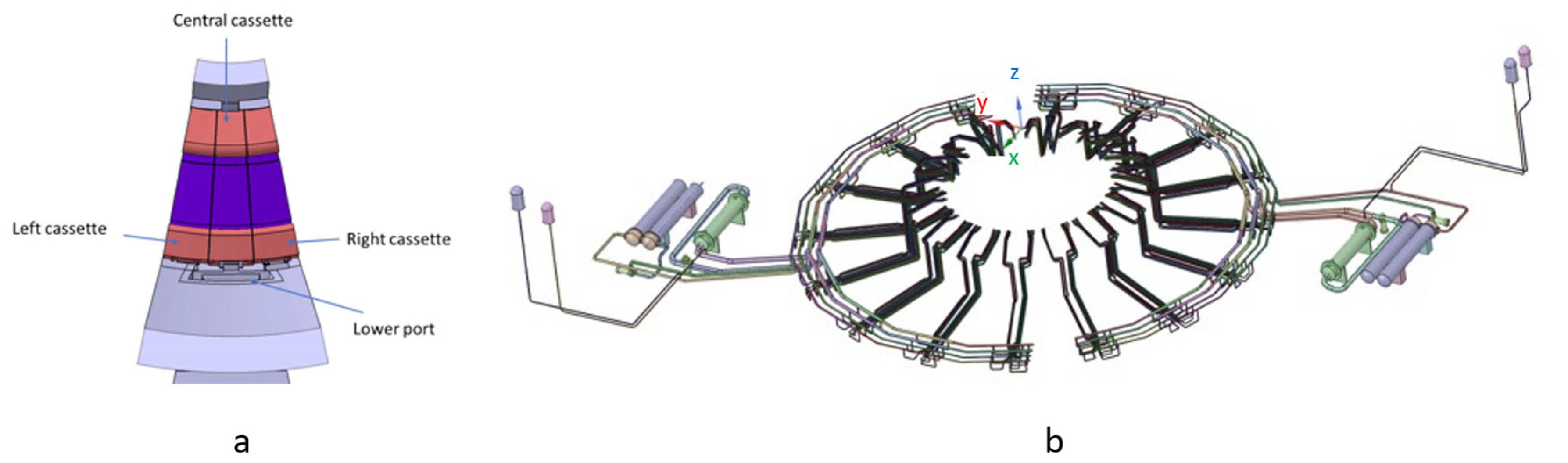
An HTS loop serving 8 out of 16 DEMO sectors for the divertor cassette (24 cassettes out of 48), with a pressure at 3.5 MPa at the cassette inlet dropping down to 2.5 MPa at hot ring collector and to about 2.3 MPa at the HW outlet. The HTS includes one heat exchanger, one pump (1.48 MPa of pump head), one pressurizer, and one cold leg from pump to cold ring distributor, then splits into 24 distributor pipes up to the in-vessel components. The coolant is then collected from the the in-vessel components by means of 24 collecting pipes into the hot ring and led to the HX by means of the hot leg.
(ii)
The HTS loop for the divertor PFU (24 PFUs out of 48) has the same equipment and layout as the divertor cassette HTS, with the pump providing 1.82 MPa of head to compensate for pressure drops.
(iii)
Divertor cassette in-vessel components include:
a.
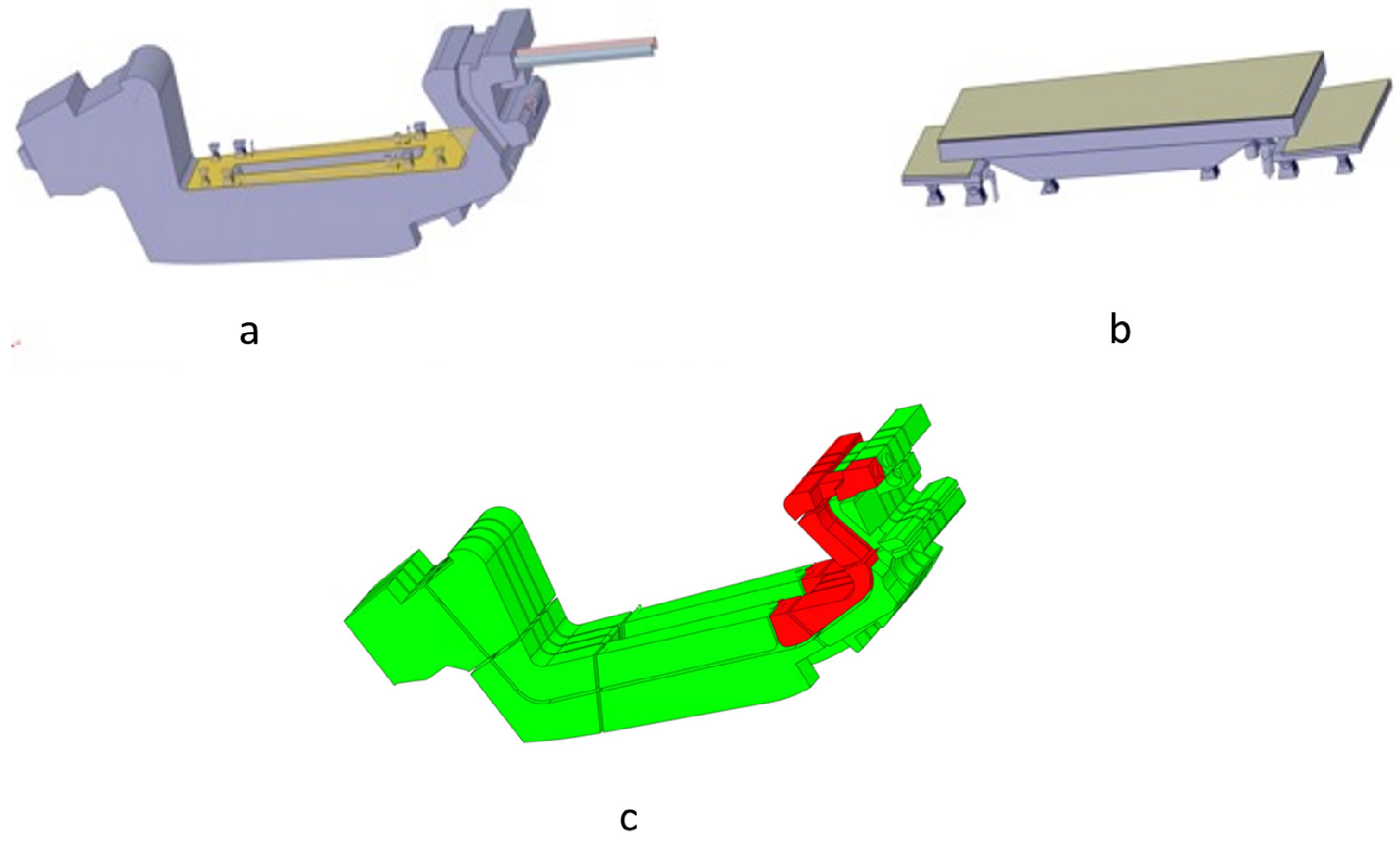
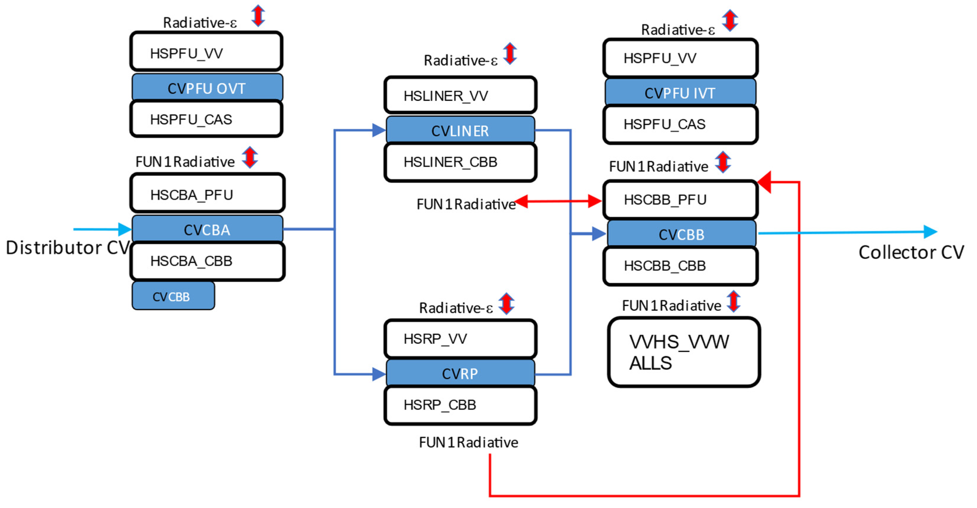
Two cassettes (the one involved in the PIE events and another corresponding with the PFU impacted by the disruption) are defined more in detail according to the scheme in (Figure 6). The cassette is modeled considering the cooling-water path across the cassette, entering a first CB-A volume (15% of cassette water volume), followed by liner and RP (accounting for 2 RP) volumes, and finally followed by a CB-B volume (accounting for the remaining 85% of the cassette volume).
b.
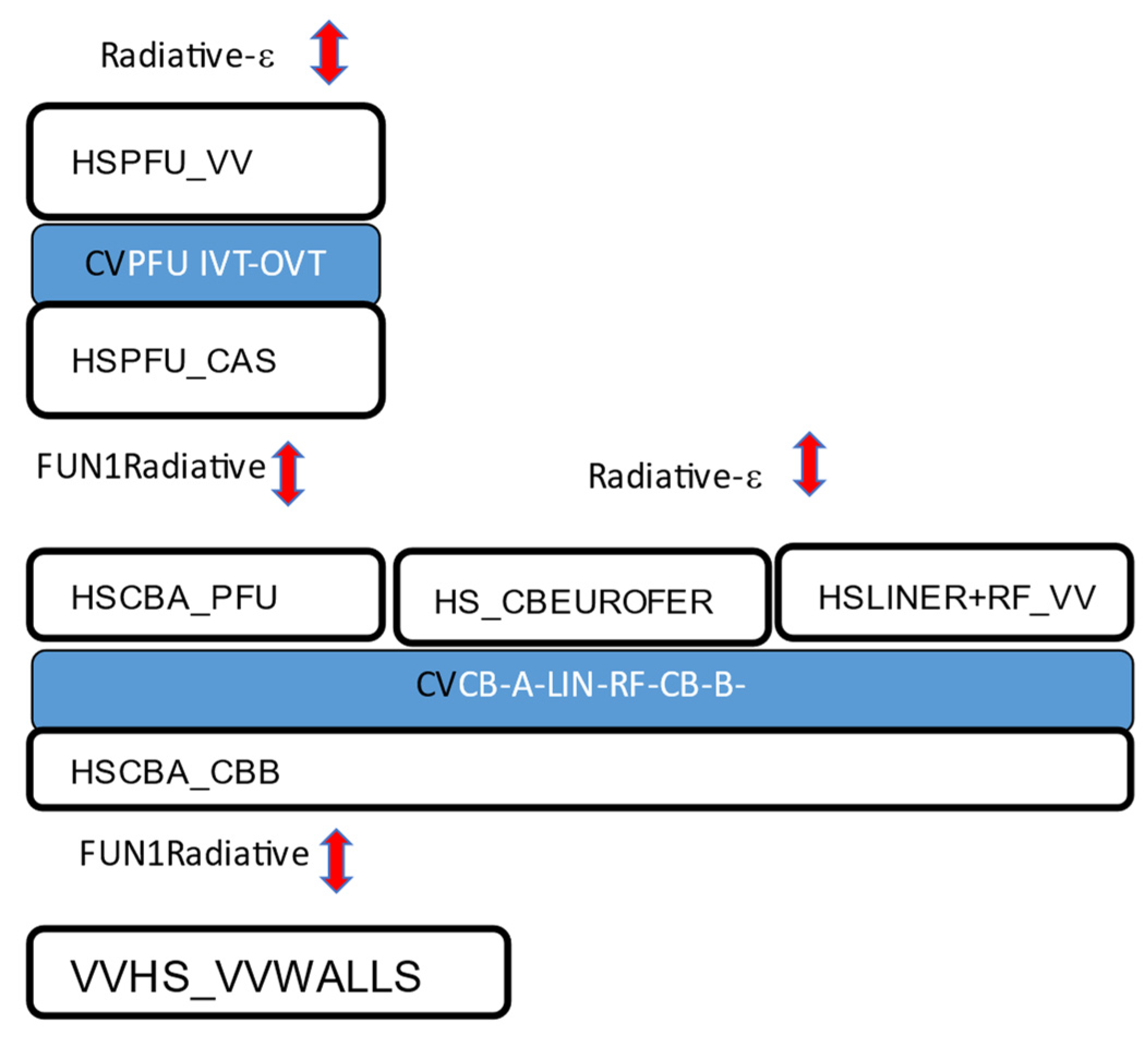
Twenty-two lumped cassettes (Figure 7) merging CB-A, CB-B, liner and RP volumes.
(iv)
Divertor target in-vessel components include:
a.
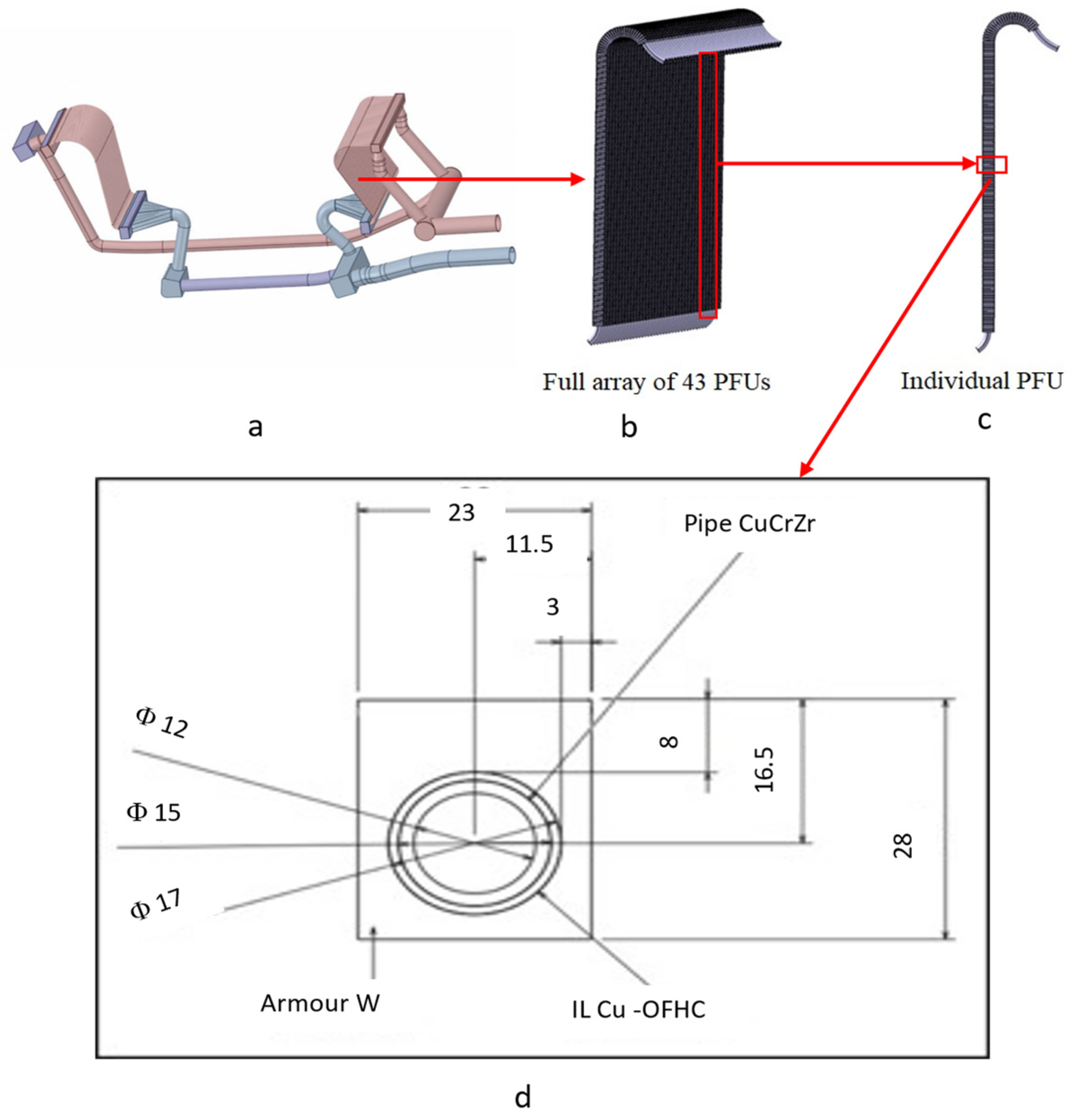
A more detailed nodalization was implemented for 2 PFU (Figure 6) representing the PFU involved in the PIE event, and the PFU impacted by the disruption, respectively. These 2 units are further composed by: an inlet CV feeding the cooling water to two separate CVs for the inner and outer vertical targets volumes respectively; a volume representing an inner vertical target; a volume representing an outer vertical target; and an outlet CV collecting water from the IVT and OVT. The target channels are merged into a unique volume equivalent to the sum of all channel volumes.
b.
Twenty-two PFU lumped units. A single CV has been defined accounting for both the inlet/outlet pipes and IVT/OVT channels equivalent volumes.
(v)
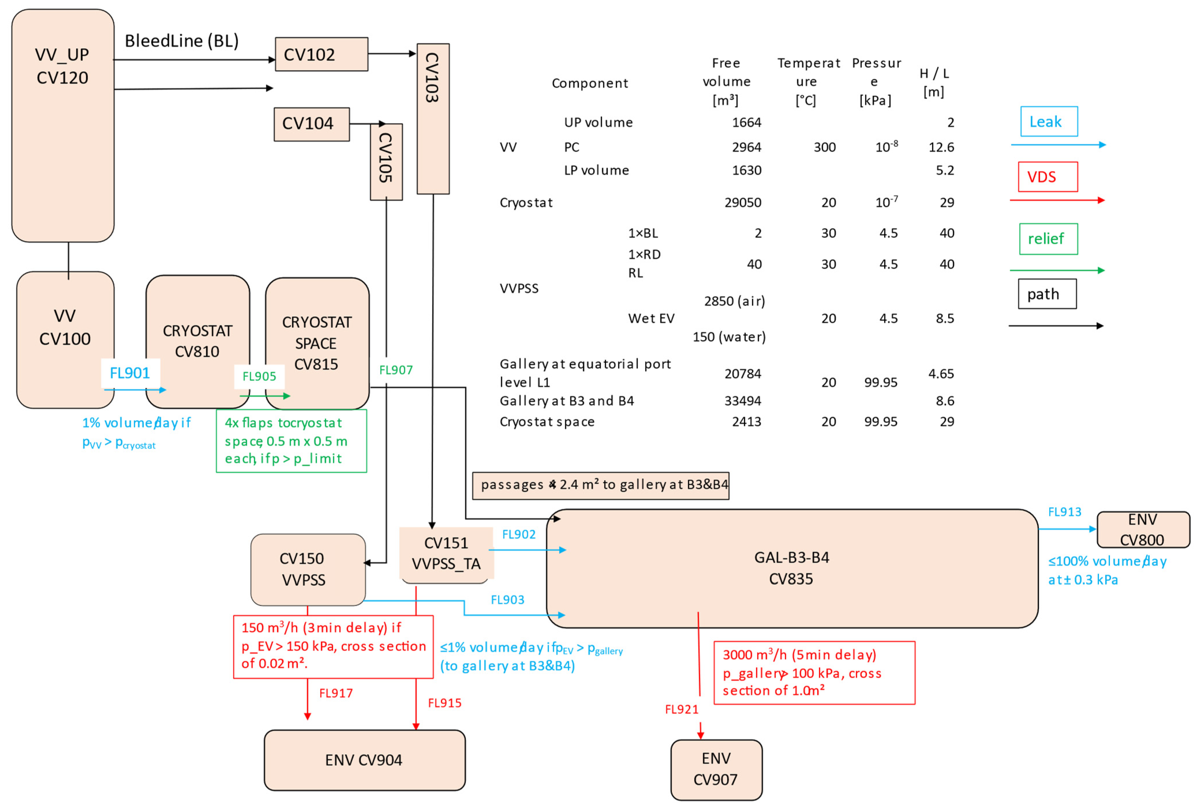
Tokamak systems: vacuum vessel and connected lower and upper port volumes; VVPSS-Ta and VVPSS volume partially filled in water and kept at a pressure of 9.5 × 10³ Pa; confinement model for tokamak systems and building including cryostat, cryostat space, and galleries.
The resulting total pool volume and mass in the PFU (in-vessel components and ex-vessel heat-transfer system) loop are 70.28 m3 and 64,816 kg respectively. The resulting total pool volume and mass in the divertor cassette (in-vessel components and ex-vesselheat-transfer system) loop are 87.71 m3 and 76,087.0 kg, respectively.
Concerning heat structure (HS) modeling, the ex-vessel components and pipework are provided with an HS representing pipes/component walls. An adiabatic condition is conservatively adopted for the boundary in contact with the environment volume atmosphere on the external surface. The in-vessel components have been provided with the HS having heat exchange with the surrounding volumes, as in Figure 6 and Figure 7.
For the PFU where the disruption impacts and the one where the break occurs and related cassettes the scheme in (Figure 6) is adopted. In particular:
(i)
Cassette HS.
a.
The CBA volume has two Eurofer HSs, one in radiative contact with the OVT and one in between the CBA and CBB CV. These two HSs are in conductive contact with MELCOR user FUN1.
b.
The liner volume has two HS, one (W + Eurofer) receiving plasma loads and one (Eurofer) in radiative connection with the cassette HS (CB-B-top). These two HSs are also in mutual conductive contact by means of MELCOR FUN1.
c.
The RP (accounting for two RP) volume has two HS, one (W + Eurofer) receiving plasma loads and one (Eurofer) in radiative contact with the cassette HS (CB-B-top). These 2 HSs are also in mutual conductive contact with FUN1.
d.
The CB-B volume has 2 HSs, one in contact with IVT and one in radiative contact with the VV walls. These 2 HSs are also in mutual conductive contact with FUN1. Other than nuclear heating, during the plasma pulse, the liner and RP units are assumed to be under a heat flux respectively of 1.0 MW/m2 and 0.2 MW/m2 from plasma. Nuclear heating (NH) during the pulse and decay heat (DH) at shutdown data are reported in Table 2.
(ii)
PFU HS.
a.
The IVT considers 2 HSs representing vertical targets towards the plasma and cassette.
b.
OVT considers 2 HS representing vertical targets towards the plasma and the cassette.
c.
One HS has been defined to represent feeding pipe walls.
Note that MELCOR FUN1 functions are used to simulate the conductive contact between the plasma-side and cassette-side HSs of the IVT and OVT volumes. Other than NH, during the plasma pulse, the PFU units are assumed to be under a heat flux of 1.5 MW/m2 from plasma (radiation and particles). Nuclear heating (during pulse) and decay heat (at shutdown) data are reported in Table 2.
For 22 PFUs, lumped model CVs and related cassettes (Figure 7):
(i)
Two HSs representing PFU vertical targets towards the plasma and the cassette and one HS representing pipe walls are implemented
(ii)
One HS (CB-A_CB-B_PFU) is the Eurofer volume accounting for the cassette in radiative contact with the PFU vertical targets; one HS represents the liner and reflector plates (RP) (W + Eurofer) receiving the plasma load and one HS (CB-A_CB-B) in Eurofer volume accounts for the remaining part of the cassette.
Additional HSs are also introduced in the model to represent the following in-VV components:
(i)
One HS representing the FW and the breeding blanket (BB) is implemented with an initial temperature of 650 K. Decay heat (at shutdown) data are reported in Table 2. This HS is coupled radiatively with the VV walls using a FUN1 function.
(ii)
Three HSs representing the PFU, cassette, and liner/RP components from the second divertor PFU and cassette loops, respectively. These HSs are coupled radiatively to each other and to the VV walls using a FUN1 function, as shown in Figure 8.
(iii)
The VV has 2 HSs representing the walls and floor (the surface under the divertor). These HSs have no nuclear heating or decay heat models and have an external layer at a fixed temperature of 195 °C representing the tokamak decay heat removal system (DHRS).
(iv)
VV-upper port has a vertical-walls HS with external layer at a fixed temperature of 195 °C Other in-vessel components
(v)
VV-lower port has a vertical-walls HS and floor HS with an external layer at a fixed temperature of 195 °C
(vi)
The VVPSS and VVPSS-A are provided with an HS representing the lateral walls initially at room temperature.
Finally, Figure 9 provides an overview of the DEMO building confinement scheme for the parts involved in the accident scope by means of possible leakage and release paths.

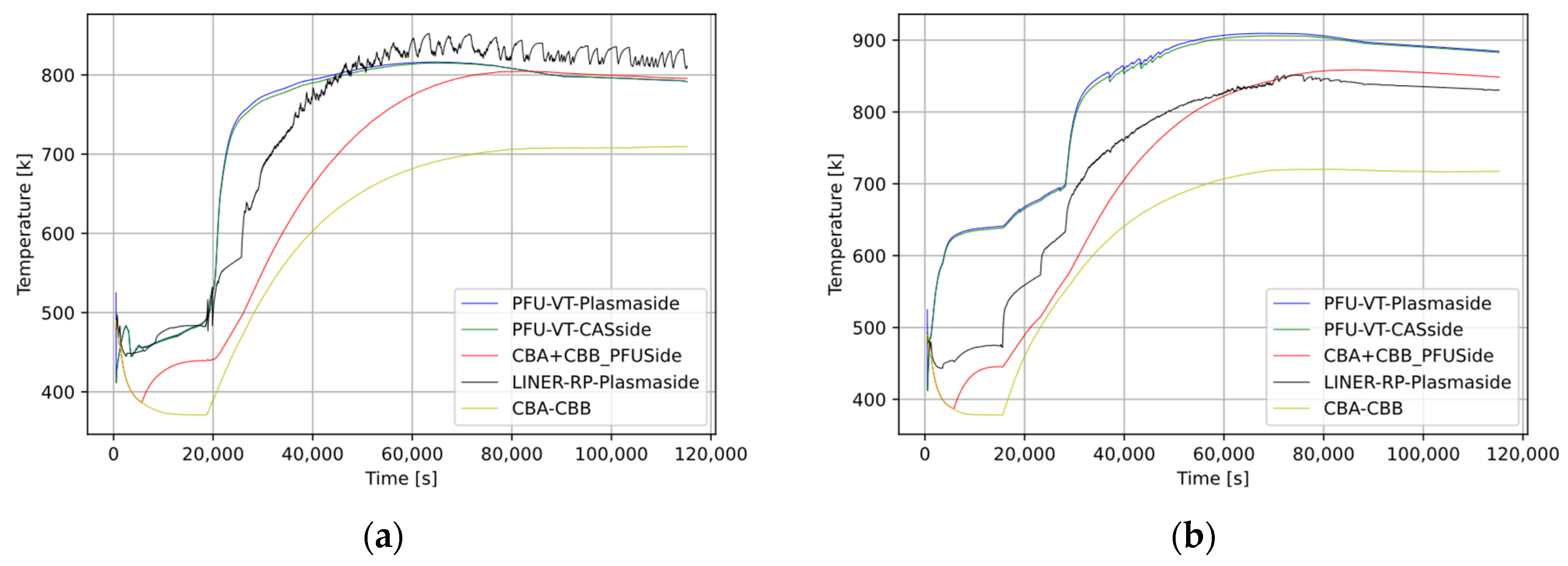
3. Results and Discussion

A steady-state period was included in the simulation to reproduce the selected loop parameters before the PIE occurrence. The duration of such a period is defined on the basis of the time needed for such parameters to stabilize. The nominal pressure pattern was reproduced for the PFU HTS loop as well as the PFU vertical heat-structure temperatures, both consistent with the design values. In the cassette HTS loop, pressure drops were reproduced in good approximation stationary values. Similarly, cassette heat-structure temperatures despite the lumped model implemented in the MELCOR code input, are in good agreement. Table 3 reports an extract of the values with an average discrepancy between the simulation and target values of 2.4%. Note that the design detail is at a preconceptual level.
After a steady-state period with the loops fully active and the plasma operating, the PIE was set to occur at time t = 500 s, and the simulation ended at t = 115,000 s.
In the PIE1 case (ref. Section 2.2), after the PIE occurrence, the water coolant inventory from the divertor cassette HTS is released from both the cassette inlet feeding pipe FL121 (break area 0.0116 m2). The mass flow rate peak is 197.96 kg/s in Cassette break (Figure 10a), while the integral of the mass flow rate (i.e., released inventory) amounts to 64,802 kg, as shown in (Figure 11a). Note that given the relevant number of user-defined FUN1 thermal coupling function between heat structures (e.g., ref Figure 6), the calculation time step is limited to < 1 × 10⁻³ s to avoid possible diverging effects in thermal coupling. This possibly results in oscillation numeric effects on the fast-varying variables as in (Figure 10).
In the PIE2 case (ref. Section 2.2), after the PIE occurrence, the water coolant is released from both the cassette and PFU inlet feeding pipe, respectively FL121 (break area 0.0116 m2) and FL101 (break area 0.0286 m2), and at the inlet of one cassette unit chosen as the break point. Due to a higher pressure (5 MPa vs. 3.5 MPa) and a bigger feeding pipe size (DN125 vs DN80) in the PFU HTS loop with respect to the CAS HTS loop, a higher mass flow rate (peak at about 391. kg/s vs 197.96 kg/s in the cassette break) at the break point is observed for the PFU break (Figure 10b). The integral of the mass flow rate over time (i.e., the released inventory) is shown in (Figure 11b). The total amounts of coolant from the break are 64,797 kg and 61,612 Kg for the cassette and PFU HTSs, respectively.
Plasma disrupts within 3 s with an unmitigated disruption on a PFU OVT, whose HS transient is reported in (Figure 12). Copper’s melting temperature is not reached, so no additional pipe breaks occur in either the PIE1 or PIE2 cases.
The released water coolant inventory vaporizes while entering the vacuum chamber and pressurizes the VV and the connected upper and lower port volumes. The resulting pressurization patterns for the PIE1 and PIE2 cases are shown in Figure 13. Despite the similar evolution of the accidents and the intervention of the foreseen mitigating systems, the timing is different, with a much quicker pressurization in PIE2, as expected. In particular, the pressure rises in the VV and the connected upper and lower port volumes, until the set-point for the pressure release towards the VVPSS-A (0.9 bar) opens within 111 s (PIE1)/47 s (PIE2), slowing the pressurization pattern, though not impeding the pressure to reach the rupture disk set-point (1.5 bar) within 252 s (PIE1)/127 s (PIE2) from the PIE. The VVPSS effectively suppresses the pressure in the VV, which returns below 1 bar in about 150 s (PIE1)/270 s (PIE2) from the PIE. Interestingly, the pressurization resulting from PIE1 (only cassette loop) is indeed faster than what was observed for the inVV LOCA from the PFU loop-only rupture studied in [11].
Figure 14a,b report heat-structure long-term peak temperatures for the main divertor structures in the PIE1 and PIE2 cases, respectively. Higher temperatures are observed in the PFU, reaching a plateau at about 900 K. Melting temperatures are not reached for either the PFU pipes or Eurofer cassettes, and therefore the presented pattern appears to meet the acceptance criteria. Figure 15a (PIE1) and 15b (PIE2) report the long-term temperature for the HS with the W layer contributing to the steam_W reactions: the FW/BB and PFU of the other divertor loop. Note that in PIE1, the divertor target PFU HSs in the long term (>10 h) are kept at a lower temperature by the presence of coolant inside the loop, though not circulating as a consequence of pump coast-down following the loss of site power co-occurring at the PIE. Further, as shown in Figure 16, the vapor temperature in the VV is higher in the initial part of the transient (10,000 s < t < 30,000 s). It should be noted that the cassette coolant is 50 °C degrees higher than the PFU coolant.
Long-term H2 mass inventory resulting from steam_W reactions (W + 3 H2O --> 3 H2 + WO3 − 156 kJ/mol [23]) is shown in Figure 17a (PIE1) and in Figure 17b (PIE2), as mobilized from the VV to the connected volumes in Figure 18a (PIE1) and in Figure 18b (PIE2). At simulation end time, the cumulative H2 in the VV and VV ports is 0.53 kg (PIE1)/0.96 kg (PIE2), while it is 1.10 kg (PIE1)/1.07 kg (PIE2) in the VVPSS and BL/RD. The total H2 production until simulation end time (32 h) amounts to 1.64 kg (PIE1)/2.03 kg (PIE2), well below the 12 kg of H2 production limit currently adopted as the acceptance criterion in DEMO. Such a value, derived as a volume-based scaling from the ITER plant, is the maximal amount allowed such that a possible resulting explosion would not exceed the VV design pressure, fixed at 2 bars.
The HTO, dust, and ACPs inventory contained in the primary confinement are mobilized mainly towards the VVPSS volumes and in much smaller amounts towards the cryostat. From the VVPSS-A originates the inventory mobilized to gallery B3-B4 as a result of a leak from the VVPSS-A, due to VVPSS-A pressure > gallery pressure condition. This condition holds true for about one hundred seconds following the PIE. This hydrogen mobilization does not impact gallery pressure, which remains below 99.5 kPa, not reaching the conditions to trigger the S-DS system. The cumulative inventories (the sum of the source terms in the volume as aerosol, in the pool, and deposited) after transient are shown in Table 4. No releases to the environment (CV800, CV904, CV907 [ref. Figure 9 for confinement scheme definitions]) are observed, as the gallery pressure remains below leakage conditions. Comparing the two cases, W dust is more mobilized towards the VVPSS in the PIE2 case, while the ACP inventory mobilization reflects the higher released inventory in the PIE 2 case.

4. Conclusions

Two in-VV LOCA accidents involving the DEMO divertor system are studied: a double-end guillotine break (DEGB) of the divertor cassette feeding pipe (PIE1) and a case when other than PIE1, a co-occurring double-end guillotine break for the divertor target PFU feeding pipe is also postulated (PIE2). The divertor cassette and target HTSs being independent, the PIE2 can be considered as a Design Extension Condition, as an accident scenario that includes combinations of initiating events. Moreover, the PFU failure as a consequence of the divertor cassette HTS breach cannot be excluded when considering the unmitigated plasma disruption following the in-VV LOCA event. In fact, even though in the present simulation the unmitigated disruption impacting the PFU significantly increases the W-layer temperature (about 2200 K) only while the Cu-layer temperature is below the melting temperature limit, the pipe structural integrity could be nonetheless compromised as a result of the temperature and pressure load combination and needs further investigation with a more specific simulation code.
Both accidents present a similar transient evolution with released coolant vaporization leading to quick VV pressurization, slowed down by the first VVPSS-A relief opening and eventually mitigated by the intervention of the much bigger VVPSS set of tanks able to keep the VV pressure below 1.5 bar. A much quicker VV pressurization, taking 125 s less to reach the VVPSS set-point, is observed in the PIE2 case.
Most of the mobilized inventory ends in the VVPSS volumes in both cases, with more mobilized W dust towards the VVPSS systems in the PIE2 case and a higher ACP inventory in the VV, clearly reflecting the higher coolant released inventory in the PIE 2 case. Concerning source terms mobilized to secondary confinement, a comparably small amount (order of 1 × 10⁻⁷ kg) of HTO and W dust is mobilized into the cryostat and gallery B3B4 due to the over-pressurization leaking model considered in the simulation. Nonetheless, no source-terms releases to the environment are observed as the gallery pressure remains below the leakage conditions for all transient periods. Heat-structure temperatures appear to stabilize below 900 K for the plasma-facing structures (PFU and FW/BB) and within the safe temperature domain considered for structural integrity. Though a relatively higher H2 production from W_water reactions at a high temperature is observed in the PIE2 case, the overall H2 inventory within the VV falls below the 12-kg accepted limit. In conclusion, despite the PIE2 case appearing more challenging than PIE1 in terms of transient speed, peak HS temperatures and mobilized source terms, no cliff-edge effects are observed, and the current design appears to be able to withstand the impact of the considered accidental load.

Author Contributions

Conceptualization, D.N.D.; methodology, D.N.D., M.D., T.P., G.C. and M.T.P.; software, D.N.D. and M.D.; validation, D.N.D. writing—original draft preparation, D.N.D.; writing—review and editing, M.D., T.P., G.C. and M.T.P. All authors have read and agreed to the published version of the manuscript.

Funding

This work has been carried out within the framework of the EUROfusion Consortium, funded by the European Union via the Euratom research and training programme (Grant Agreement No 101052200). Views and opinions expressed are however those of the author(s) only and o do not necessarily reflect those of the European Union or the European Commission. Neither the European Union nor the European Commission can be held responsible for them.

Conflicts of Interest

The authors declare no conflict of interest. The funders had no role in the design of the study; in the collection, analyses, or interpretation of data; in the writing of the manuscript, or in the decision to publish the results.

Nomenclature

ACPActivated Corrosion Products
BBBreeder Blanket
BDBABeyond Design-Basis Accident
CASCassette
CBCassette Body
CVControl Volume
DBADesign-Basis Accident
DECDesign Extension Conditions
DEGBDouble-End Guillotine Break
DIV/DVDivertor
ENVEnvironment (Control Volume)
FLFlow Path Line
FWFirst Wall
GAL-B3-B4Gallery at building levels 3–4
HSHeat Structure
HTSHeat-Transfer System
HXHeat Exchanger
IVTInner Vertical Target
LOCALoss of Coolant Accident
LPLower Port
OVTOuter Vertical Target
PCPort Cell
PFCPlasma-Facing Components
PFUPlasma-Facing Units
PIEPostulated Initiating Event
SSCSystems Structures and Components
VDSVenting Detritiation System.
VVVacuum Vessel
VV-LPVacuum VesselLower Port
VV-PCVacuum VesselPlasma Chamber
VV-UPVacuum VesselUpper Port
VVPSSVacuum Vessel Pressure Suppression System

References

  1. Federici, G.; Bachmann, C.; Barucca, L.; Baylard, C.; Biel, W.; Boccaccini, L.V.; Bustreo, C.; Ciattaglia, S.; Cismondi, F.; Corato, V. Overview of the DEMO staged design approach in Europe Nucl. Fusion 2019, 59, 066013. [Google Scholar] [CrossRef] [Green Version]
  2. Federici, G. Special Issue on European Programme towards DEMO: Outcome of the Pre-Conceptual Design Phase. Fusion Eng. Des. 2022, 178, 113103. [Google Scholar] [CrossRef]
  3. You, J.H.; Mazzone, G.; Visca, E.; Greuner, H.; Fursdon, M.; Addab, Y.; Bachmann, C.; Barrett, T.; Bonavolontà, U.; Böswirth, B.; et al. Divertor of the European DEMO: Engineering and technologies for power exhaust. Fusion Eng. Des. 2022, 175, 113010. [Google Scholar] [CrossRef]
  4. IAEA. Considerations on the Application of the IAEA Safety Requirements for the Design of Nuclear Power Plants; IAEA-TECDOC-1791; IAEA: Vienna, Austria, 2016. [Google Scholar]
  5. Merrill, B.J. Recent Updates to the MELCOR 1.8.2 Code for ITER Applications; Idaho National Laboratory: Idaho Falls, ID, USA, 2007; p. INL/EXT-07-12493. [Google Scholar]
  6. Merrill, B.J.; Humrickhouse, P.W. Masashi Shimada, Recent development and application of a new safety analysis code for fusion reactors. Fusion Eng. Des. 2016, 109–111, 970–974, ISSN 0920-3796. [Google Scholar] [CrossRef] [Green Version]
  7. Dongiovanni, D.N.; D’Onorio, M. Loss of Liquid Lithium Coolant in an Accident in a DONES Test Cell Facility. Energies 2021, 14, 6569. [Google Scholar] [CrossRef]
  8. D’Onorio, M.; Dongiovanni, D.N.; Ricapito, I.; Vallory, J.; Porfiri, M.T.; Pinna, T.; Caruso, G. Supporting analysis for WCLL test blanket system safety. Fusion Eng. Des. 2021, 173, 112902. [Google Scholar] [CrossRef]
  9. Pinna, T.; Dongiovanni, D.N.; Iannone, F. Functional analysis for complex systems of nuclear fusion plant. Fusion Eng. Des. 2016, 109–111, 795–800. [Google Scholar] [CrossRef]
  10. Pinna, T.; Dongiovanni, D.N.; Ciattaglia, S.; Barucca, L. Safety important classification of EU DEMO components. Fusion Eng. Des. 2019, 146, 631–636. [Google Scholar] [CrossRef]
  11. Dongiovanni, D.N.; Pinna, T.; Porfiri, M.T. DEMO Divertor preliminary safety assessment. Fusion Eng. Des. 2021, 169, 112475. [Google Scholar] [CrossRef]
  12. Caruso, G.; Ciattaglia, S.; Colling, B.; di Pace, L.; Dongiovanni, D.N.; D’Onorio, M.; Garcia, M.; Jin, X.Z.; Johnston, J.; Leichtle, D.; et al. DEMO—The main achievements of the Pre—Concept phase of the safety and environmental work package and the development of the GSSR. Fusion Eng. Des. 2022, 176, 113025. [Google Scholar] [CrossRef]
  13. D’Onorio, M.; D’Amico, S.; Froio, A.; Porfiri, M.T.; Spagnuolo, G.A.; Caruso, G. Benchmark analysis of in-vacuum vessel LOCA scenarios for code-to-code comparison. Fusion Eng. Des. 2021, 173, 112938. [Google Scholar] [CrossRef]
  14. D’Onorio, M.; Giannetti, F.; Porfiri, M.T.; Caruso, G. Preliminary sensitivity analysis for an ex-vessel LOCA without plasma shutdown for the EU DEMO WCLL blanket concept. Fusion Eng. Des. 2020, 158, 111745. [Google Scholar] [CrossRef]
  15. D’Onorio, M.; Giannetti, F.; Porfiri, M.T.; Caruso, G. Preliminary safety analysis of an in vessel LOCA for the EU-DEMO WCLL blanket concept. Fusion Eng. Des. 2020, 155, 111560. [Google Scholar] [CrossRef]
  16. D’Onorio, M.; Giannetti, F.; Caruso, G.; Porfiri, M.T. In-box LOCA accident analysis for the European DEMO water-cooled reactor. Fusion Eng. Des. 2019, 146, 732–735. [Google Scholar] [CrossRef] [Green Version]
  17. Marzullo, D.; Dongiovanni, J.-H. You Systems engineering approach for pre-conceptual design of demo divertor. In Proceedings of the 2018 26th International Conference on Nuclear Engineering—ICONE26-82421, London, UK, 22–26 July 2016. [Google Scholar]
  18. Mazzone, G.; You, J.; Bachmann, C.; Bonavolontà, U.; Cerri, V.; Coccorese, D.; Dongiovanni, D.; Flammini, D.; Frosi, P.; Forest, L.; et al. Eurofusion-DEMO Divertor—Cassette Design and Integration. Fusion Eng. Des. 2020, 157, 111656. [Google Scholar] [CrossRef]
  19. You, J.-H.; Visca, E.; Bachmann, C.; Barrett, T.; Crescenzi, F.; Fursdon, M.; Greuner, H.; Greuner, D.; Languille, P.; Li, M.; et al. European DEMO divertor target: Operational requirements and material-design interface. Nucl. Mater. Energy 2016, 9, 171–176. [Google Scholar] [CrossRef] [Green Version]
  20. Gaganidze, E.; Gillemot, F.; Szenthe, I.; Gorley, M.; Rieth, M.; Diegele, E. Development of EUROFER97 database and material property handbook. Fusion Eng. Des. 2018, 135, 9–14. [Google Scholar] [CrossRef] [Green Version]
  21. Pinna, T.; Carloni, D.; Carpignano, A.; Ciattaglia, S.; Johnston, J.; Porfiri, M.T.; Savoldi, L.; Taylor, N.; Sobrero, G.; Uggenti, A.C.; et al. Identification of accident sequences for the DEMO plant. Fusion Eng. Des. 2017, 124, 1277–1280. [Google Scholar] [CrossRef]
  22. D’Onorio, M.; Caruso, G. Pressure suppression system influence on vacuum vessel thermal-hydraulics and on source term mobilization during a multiple first Wall—Blanket pipe break. Fusion Eng. Des. 2021, 164, 112224. [Google Scholar] [CrossRef]
  23. Mantas, P. DEMO Safety Data List (SDL), EUROfusion IDM 2NUYKH v1.1. Project Internal document for safety analysis.
  24. Taylor, N.; Ciattaglia, S.; Coombs, D.; Jin, X.Z.; Johnston, J.; Liger, K.; Mazzini, G.; Mora, J.C.; Pinna, T.; Porfiri, M.T.; et al. Safety and environment studies for a European DEMO design concept. Fusion Eng. Des. 2019, 146, 111–114. [Google Scholar] [CrossRef]
Figure 1. Divertor cassette (a), divertor target (b), assembly of cassette and target (c).
Energies 15 08879 g001
Figure 2. Divertor cassette body (a), cassette liner (b) and reflector plates (lateral) (b), Cassette Body-A (red) and Cassette Body-B (green) volumes (c).
Energies 15 08879 g002
Figure 3. Divertor targets (a), array of PFU detail (b), individual PFU (c), overview of PFU tile and pipe dimensions (reported in mm) (d).
Energies 15 08879 g003
Figure 4. Divertor cassette and target assembly for a segment (a), heat-transfer system for Divertor cassette and target for DEMO’s 16 sectors (b).
Energies 15 08879 g004
Figure 5. Overview of divertor system nodalization (a) and data for main divertor system CVs (b).
Energies 15 08879 g005aEnergies 15 08879 g005b
Figure 6. Overview of divertor in-VV volumes system nodalization: detailed volumes for PFU and cassette, related heat structures and related coupling. Control Volumes (CV) are shown as blue-shaded boxes, Heat Structures (HS) are shown as white boxes, blue arrows show the water flow in normal conditions, red arrows show heat transfer mechanisms modeled across HS (FUN1 functions) or radiative towards plasma chamber.
Energies 15 08879 g006
Figure 7. Overview of divertor in-VV volumes system nodalization: detailed volumes for PFU and cassette, related heat structures and related coupling. Control Volumes (CV) are shown as blue shaded boxes, Heat Structures (HS) are shown as white boxes, red arrows show heat transfer mechanisms modeled across HS (FUN1 functions) or radiative towards plasma chamber.
Energies 15 08879 g007
Figure 8. In-vessel heat structure coupling. Control Volumes (CV) are shown as blue shaded boxes, Heat Structures (HS) are shown as white boxes, red arrows show heat transfer mechanisms modeled across HS (FUN1 functions) or radiative towards plasma chamber.
Energies 15 08879 g008
Figure 9. Tokamak confinement model implementation. VV-UP vacuum vessel PC plasma chamber, UP upper port, LP lower port. VVPSS vacuum vessel pressure suppression system (Tank A), ENV environment volumes, GAL-B3-B4 Gallery at building levels 3–4, VDS venting detritiation system.
Energies 15 08879 g009
Figure 10. Transient mass flow rate from cassette feeding pipe break in PIE1 (a) and PIE2 (b) cases.
Energies 15 08879 g010
Figure 11. Released inventory from break in PIE1 (a) and PIE2 (b) cases.
Energies 15 08879 g011
Figure 12. Temperature transient on HS impacted by disruption. Temperatures for W (L1), Cu (L2) and CuCrZr (L3) layers of the PFU vertical target HS are shown.
Energies 15 08879 g012
Figure 13. Pressure transient in VV and pressure-suppression volumes in PIE1 (dashed line) and PIE2 cases.
Energies 15 08879 g013
Figure 14. Long-term temperature pattern in divertor HTS object of break PIE1 (a) and PIE2 (b) cases.
Energies 15 08879 g014
Figure 15. Long-term temperature pattern in other in-VV HS PIE1 (a) and PIE2 (b) cases.
Energies 15 08879 g015
Figure 16. Vapor temperature transient in VV volume in PIE1 (dashed line) and PIE2 cases.
Energies 15 08879 g016
Figure 17. H2 inventory over time in selected CVs for PIE1 (a) and PIE2 (b) cases.
Energies 15 08879 g017
Figure 18. H2 mobilization from VV to connected CV for PIE1 (a) and PIE2 (b) cases.
Energies 15 08879 g018
Table 1. PHTS summary data for PFU and cassette loop.
HTS PFU Loop 24 UnitsHTS Cassette Loop 24 Units
Loop nominal Thermal Power [MW]6857.6
Coolant Tin [°C]130180
Coolant Tout [°C]136210
Coolant Pin [MPa]53.5
Table 2. Data exploited for modeling nuclear heating (NH) power (occurring during the plasma pulse) and decay heat (DH) power (occurring after plasma shutdown).
HS TAGNH [W]DH 1 s [W]DH 1 d [W]DH 1 Week [W]DH 1 Year [W]
DIV Cassette (1 module)2.37 × 1063.96 × 1048.60 × 1032.56 × 1034.60 × 102
DIV PFU (1 module)4.66 × 1051.72 × 1047.73 × 1038.52 × 1025.46 × 101
BB (all modules)2.21 × 1071.92 × 1072.26 × 1061.25 × 1062.20 × 105
Table 3. Selected parameters considered for steady-state validation.
Variable DescriptionTargetSimulationDiscrepancy
DIV PFU Inlet Pressure5.0 MPa4.8 MPa4.7%
DIV PFU Outlet Pressure4.2 MPa4.1 MPa2.6%
DIV Cassette ColdLeg Pressure3.5 MPa3.7 MPa6.5%
DIV Cassette HotLeg Pressure2.6 MPa2.7 MPa4.0%
PFU Vertical Heat Structure—Plasma Side519 K520 K0.9%
PFU Vertical Heat Structure—Cassette Side418 K418 K0.2%
CB-A Heat Structure—Plasma Side521 K519 K0.3%
CB-A/CB-B Heat Structure—Plasma Side511 K501 K2.1%
Cassette Liner and Reflector Heat Structure—Cassette Side518 K509 K1.7%
Cassette Liner and Reflector Heat Structure—Plasma Side556 K536 K3.7%
Table 4. Source terms mobilization at 32 h for considered accident cases.
Source Terms TypeVolume/RoomInventory [kg]
PIE1 Case
Inventory in Volume [kg] PIE1 Case
HTOVV + VVUP + VVLP3.0223.605
VVPSS/extensions14.73314.154
GalB3B41.87 × 10 −71.57 × 10⁻⁷
Cryostat1.14 × 10−51.48 × 10⁻⁵
Tungsten dustVV + VVUP + VVLP407.29277.43
VVPSS/extensions435.39684.18
GalB3B42.13 × 10−72.65 × 10⁻⁷
Cryostat4.74 × 10−64.01 × 10⁻⁶
ACPVV + VVUP + VVLP2.115.419
VVPSS/extensions-1.17 × 10−8
Publisher’s Note: MDPI stays neutral with regard to jurisdictional claims in published maps and institutional affiliations.

