
Analysis of Surrounding Rock Control Technology and Its Application on a Dynamic Pressure Roadway in a Thick Coal Seam
 , ,
, ,
Abstract
:1. Introduction
2. Project Overview
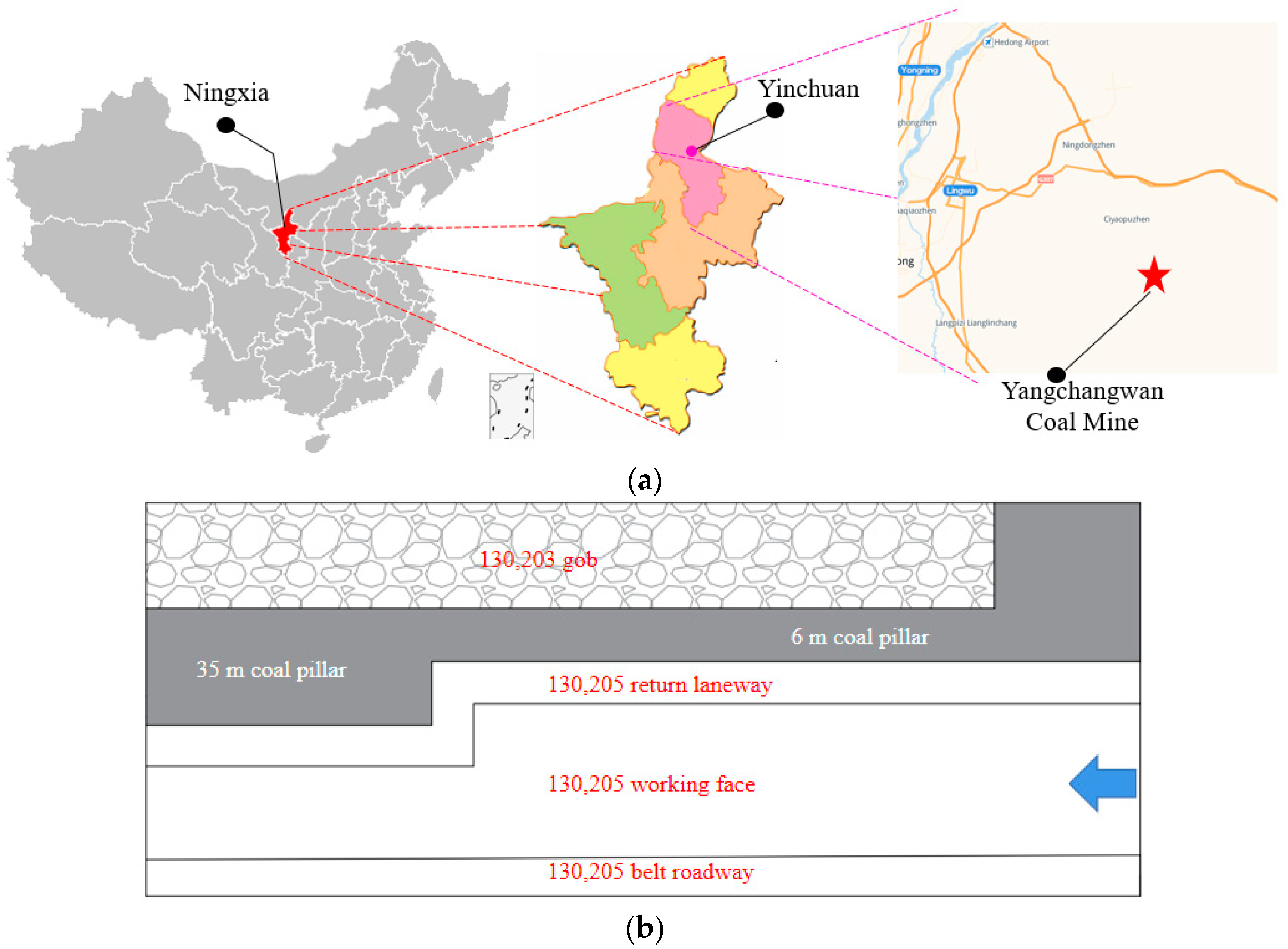
2.1. Study Area
2.2. Original Support Scheme and Roadway Status
2.3. Behavior Characteristics of Large Coal Pillars
- Faults around the roadway mainly include F20, F23, and the five-knot anticline. In this area, the roadway was not only affected by the original gravity stress but it was also affected by residual tectonic stress, especially by an increase in horizontal tectonic stress, resulting in serious damage to the roadway roof and obvious net pocket subsidence.
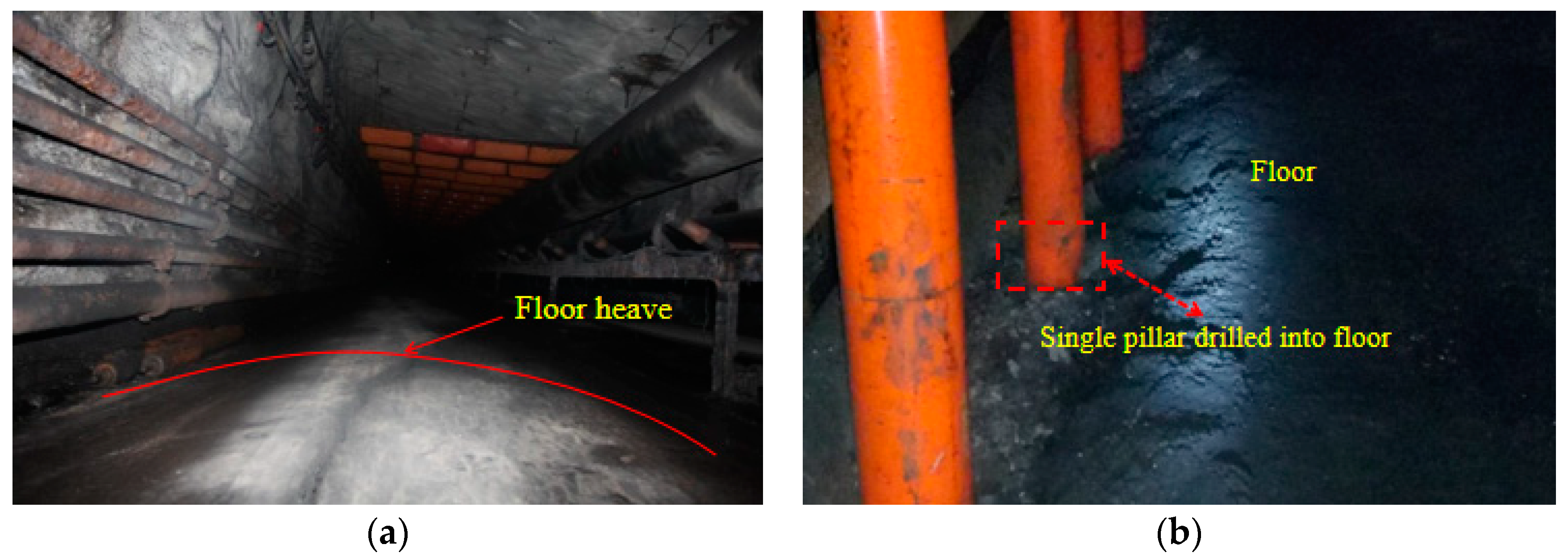
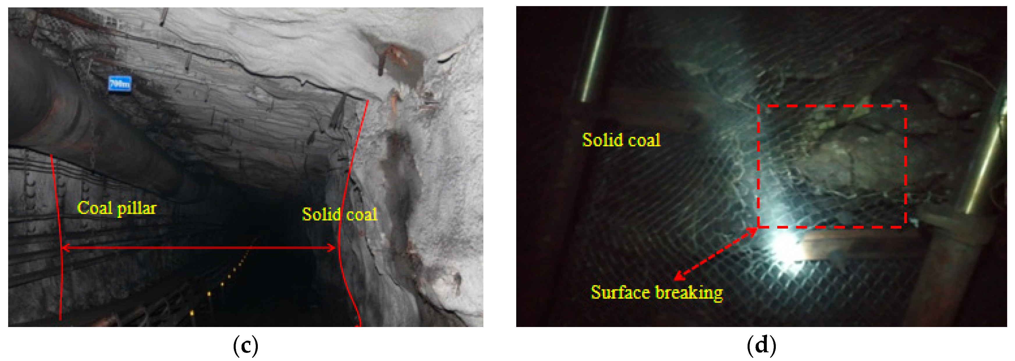
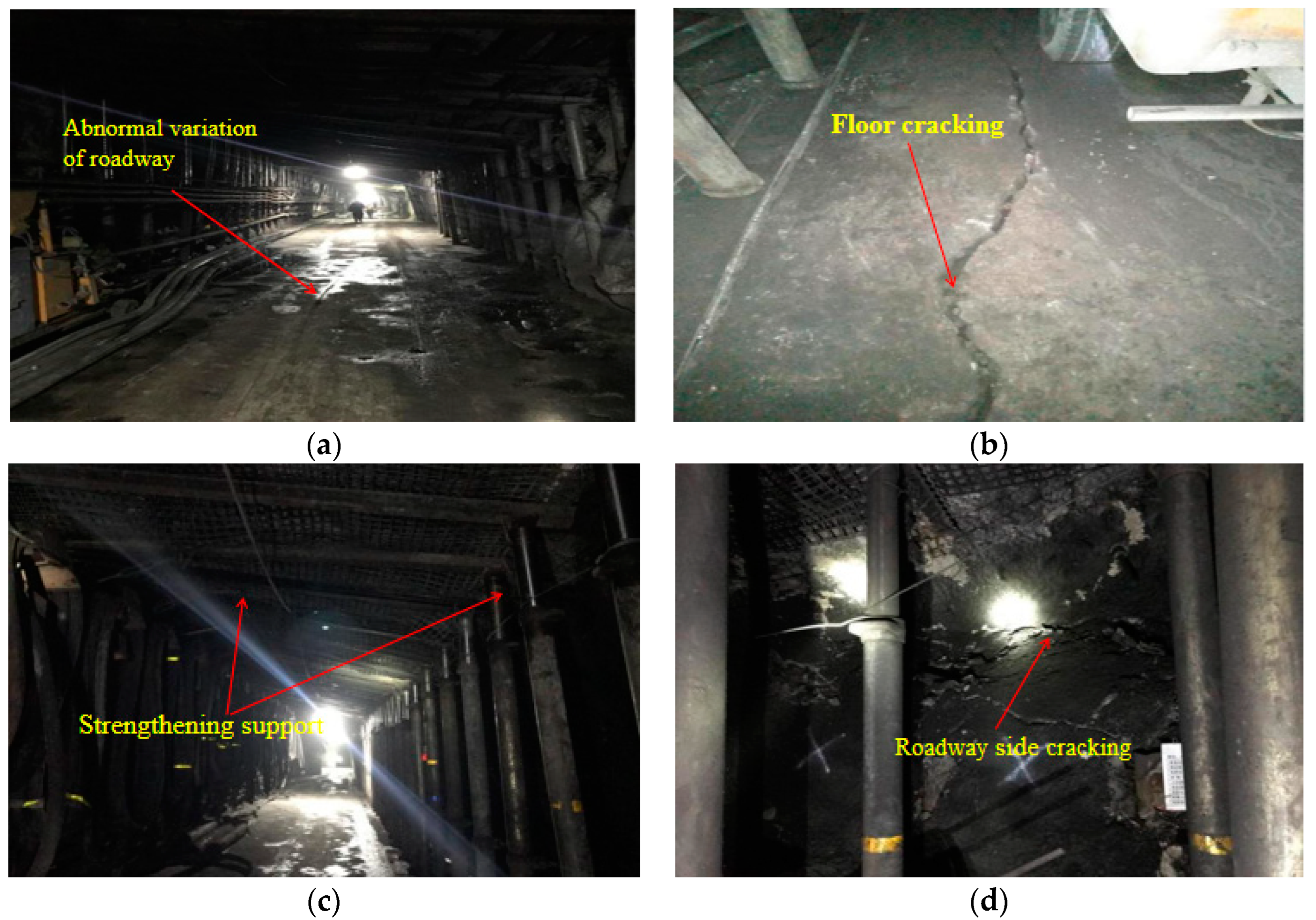
- Large initial deformation rate. After tunnel excavation, the initial deformation speed of the surrounding rock was fast, and it was subjected to high stress for a long period of time. Through observation, floor local uplift was seen (Figure 3a). Over time, the deformation of the bottom plate increased, and phenomena such as bending deformation of the steel belt and drilling of the column were observed (Figure 3b).
- Asymmetrical deformation of roadway surrounding rock. The maximum deformation of the solid-coal surrounding rock was about 633 mm, and the maximum deformation of the coal-pillar-side surrounding rock was about 170 mm. The approaching amount of the solid-coal side was significantly greater than that of the coal-pillar side. On the coal-pillar side, a coal body falling off was identified (Figure 3c). The falling coal body could be directly correlated to abutment pressure distribution in the mine. As the solid-coal side was closer to peak abutment pressure, the stress in the solid coal increased. This resulted in large deformation with coal readily falling off and damage to the coal side. As the side of the coal pillar was far from the peak value of abutment pressure, it was in a stable internal stress field. Moreover, the coal pillar had been reinforced by grouting, and its mechanical properties were enhanced. This resulted in small deformation and small ground pressure behavior strength, which mainly manifested itself as local cracking, and bolt-extrusion failure (Figure 3d).
2.4. Failure Principle of the Large Coal Pillar Roadway
2.4.1. Time–Space Effect of Mining Roadway Failure
2.4.2. Failure Process of Roadway Surrounding Rock
3. Principle of Small Coal Pillar Roadway Protection and Surrounding Rock Control in Synergy
3.1. Deformation Failure Characteristics and Instability Mechanism of a Small Coal Pillar
3.1.1. Deformation and Failure Characteristics of a Small Coal Pillar
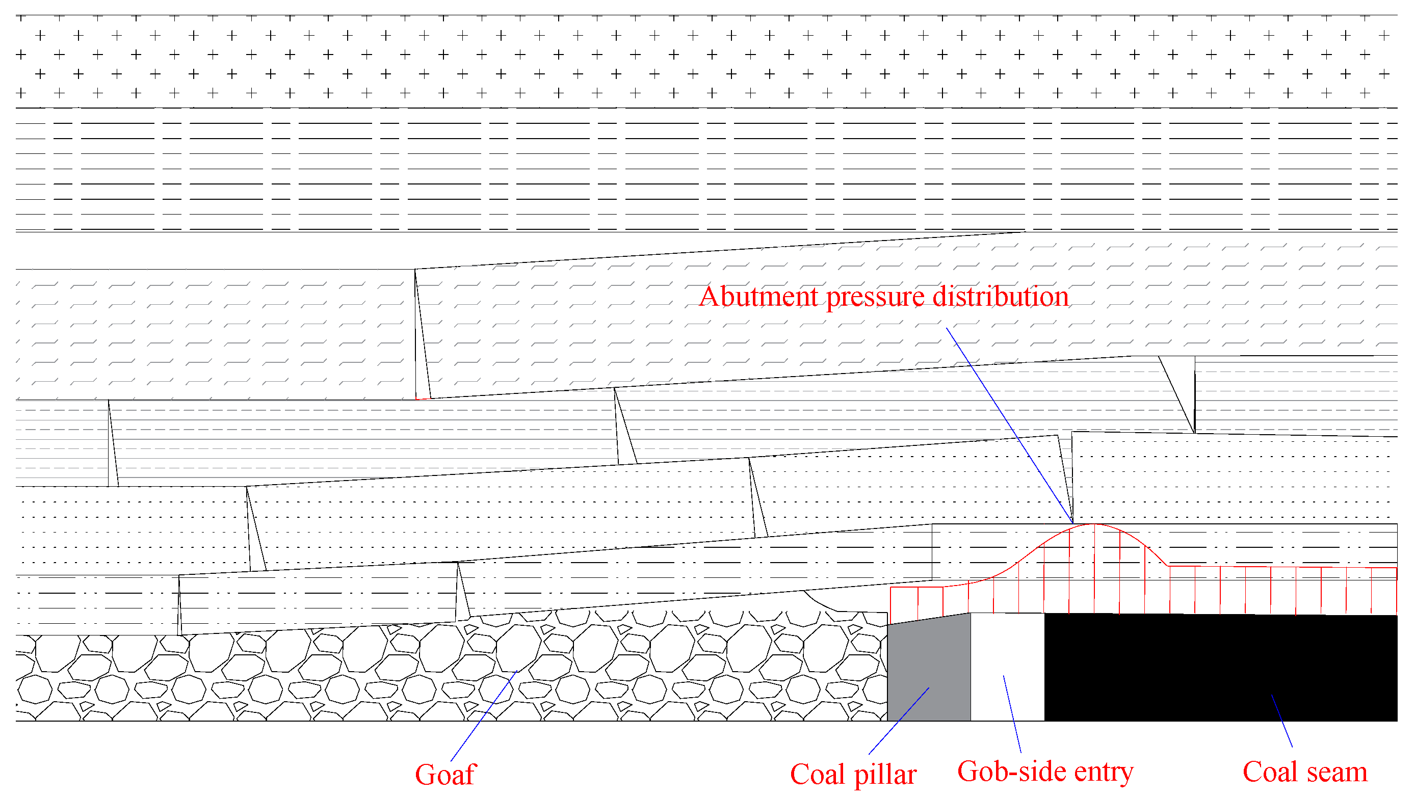
- Owing to the influence of secondary mining, mine ground pressure shows certain periodic regularity. During excavation, deformation along the gob side is greater than that along the solid-coal side, and during the mining of the roadway, deformation along the solid-coal side is greater than that along the gob side. For the gob-side roadway with a small coal pillar with moderately stable surrounding rock, the stress peak will be about 40 m from the front of the working face, having a leading influence distance of about 100 m. The surrounding rock of the roadway in the 0–10 m range in front of the working face will be severely deformed, and the relative displacement of the two sides will increase by about 10 times. The displacement of the roof and floor of the gob-side roadway increases 5–10 times more than that along the solid-coal roadway [57,58,59,60].
- Due to differences in the depth an angle of dip of the coal seam, the compression direction and coal strength of the roadway differ. Failure characteristics and deformation differ as well. When the two sides of the roadway along the goaf are in the same working condition, the rock surrounding the roadway is subjected to asymmetrical loads, resulting in asymmetric deformation and failure [61,62,63].
- The initial deformation rate is large. After roadway excavation, the initial deformation rate is large, taking place over a long time period under the action of mine pressure and having obvious rheological effects. If effective control measures are not taken, the deformation of the surrounding rock will continue to increase, eventually resulting in roadway instability and failure.
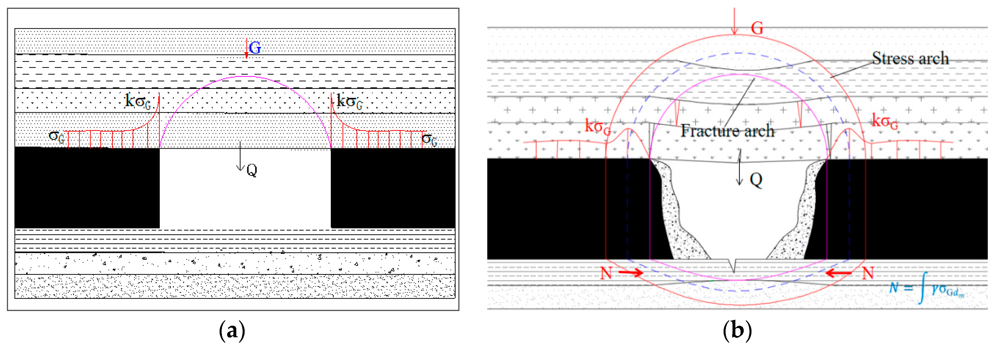
3.1.2. Instability Mechanism of a Small Coal Pillar
3.2. Surrounding Rock Control in a Synergy Scheme and Parameter Design
3.2.1. Coal Pillar Size Optimization Design
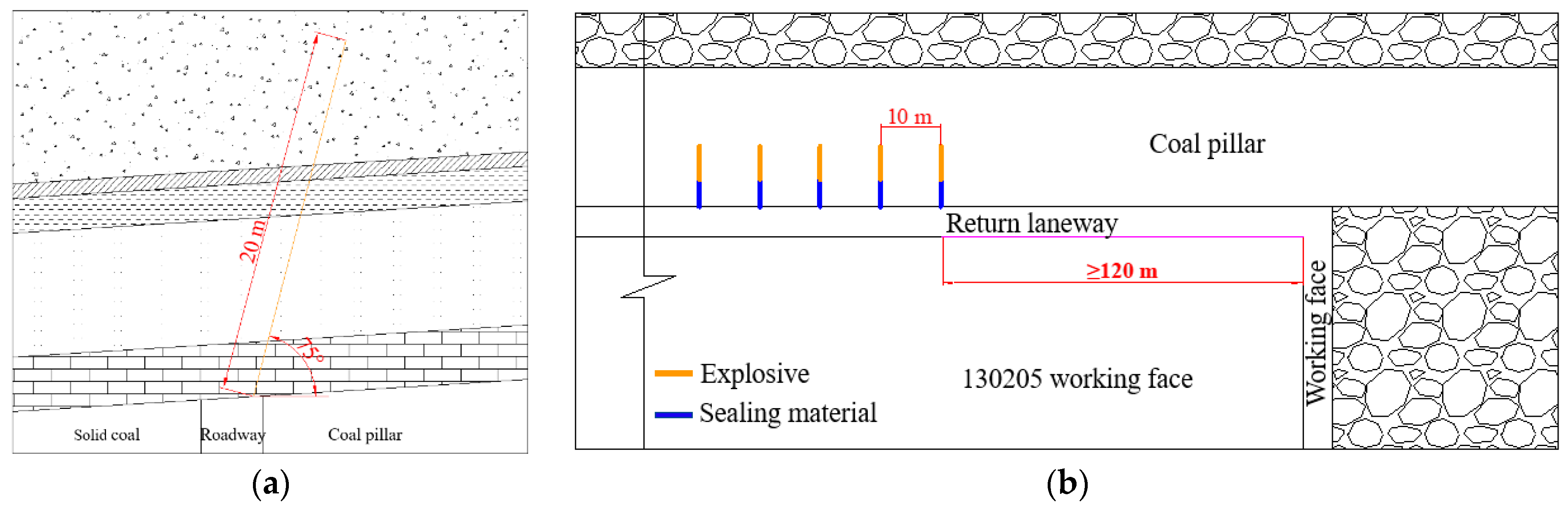
3.2.2. Roof Blasting Pressure Relief Scheme Design
3.2.3. Small Coal Pillar Grouting Reinforcement
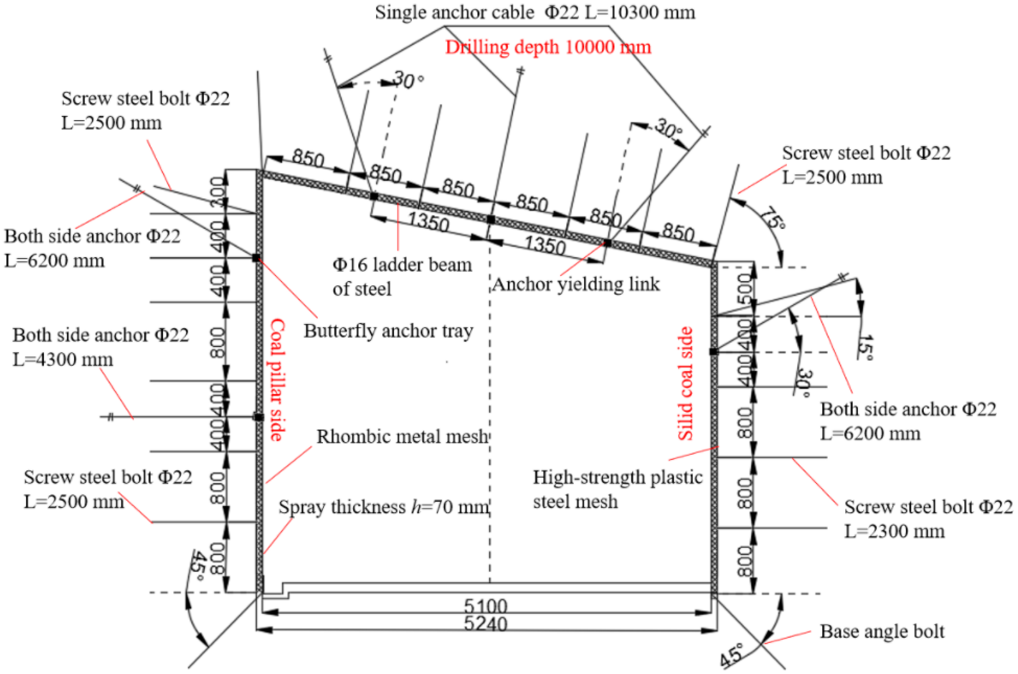
3.2.4. Roadway Support Scheme Design
4. Investigating the Effect of Small Coal Pillars on Roadway Protection
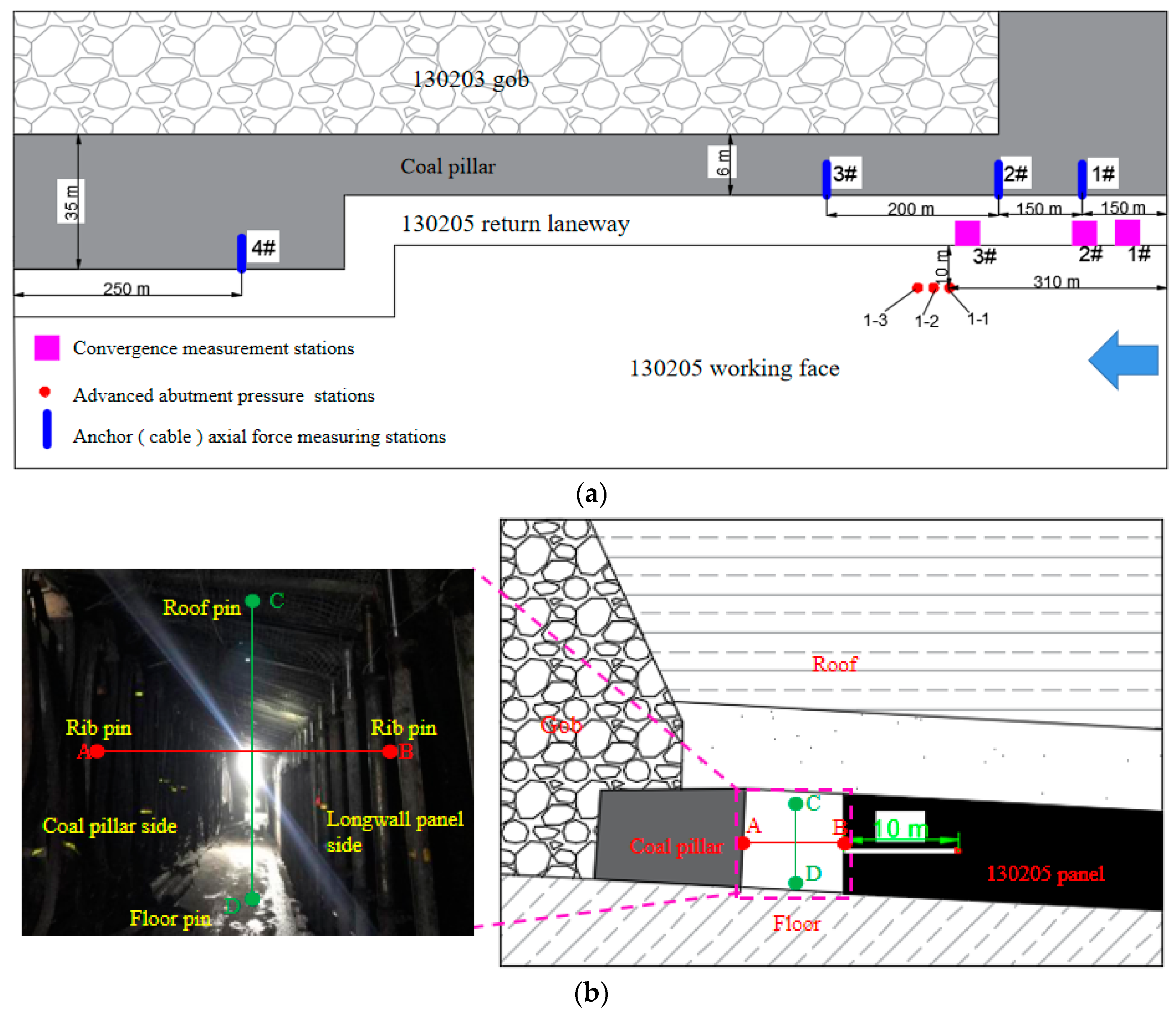
4.1. Observation Scheme
4.1.1. Monitoring Scheme of Surrounding Rock Movement
4.1.2. Monitoring of Axial Force Variation of the Anchor Cable
4.1.3. Monitoring Advanced Abutment Pressure
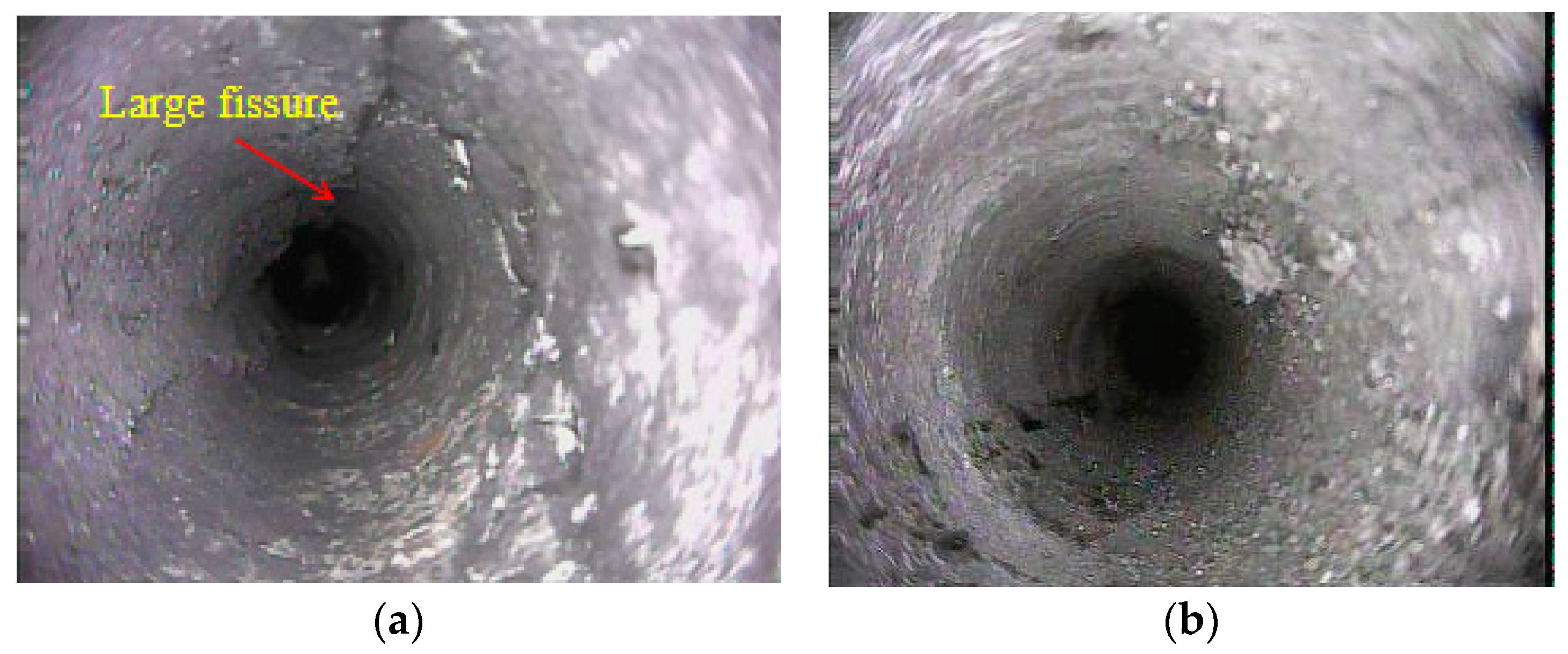
4.1.4. Detection of Fracture Morphology before and after Coal Pillar Grouting
4.2. Implementation Effect
4.2.1. Mine Pressure Characteristics
4.2.2. Convergence Deformation of the Roadway
4.2.3. Axial Force Variation of the Anchor Cable
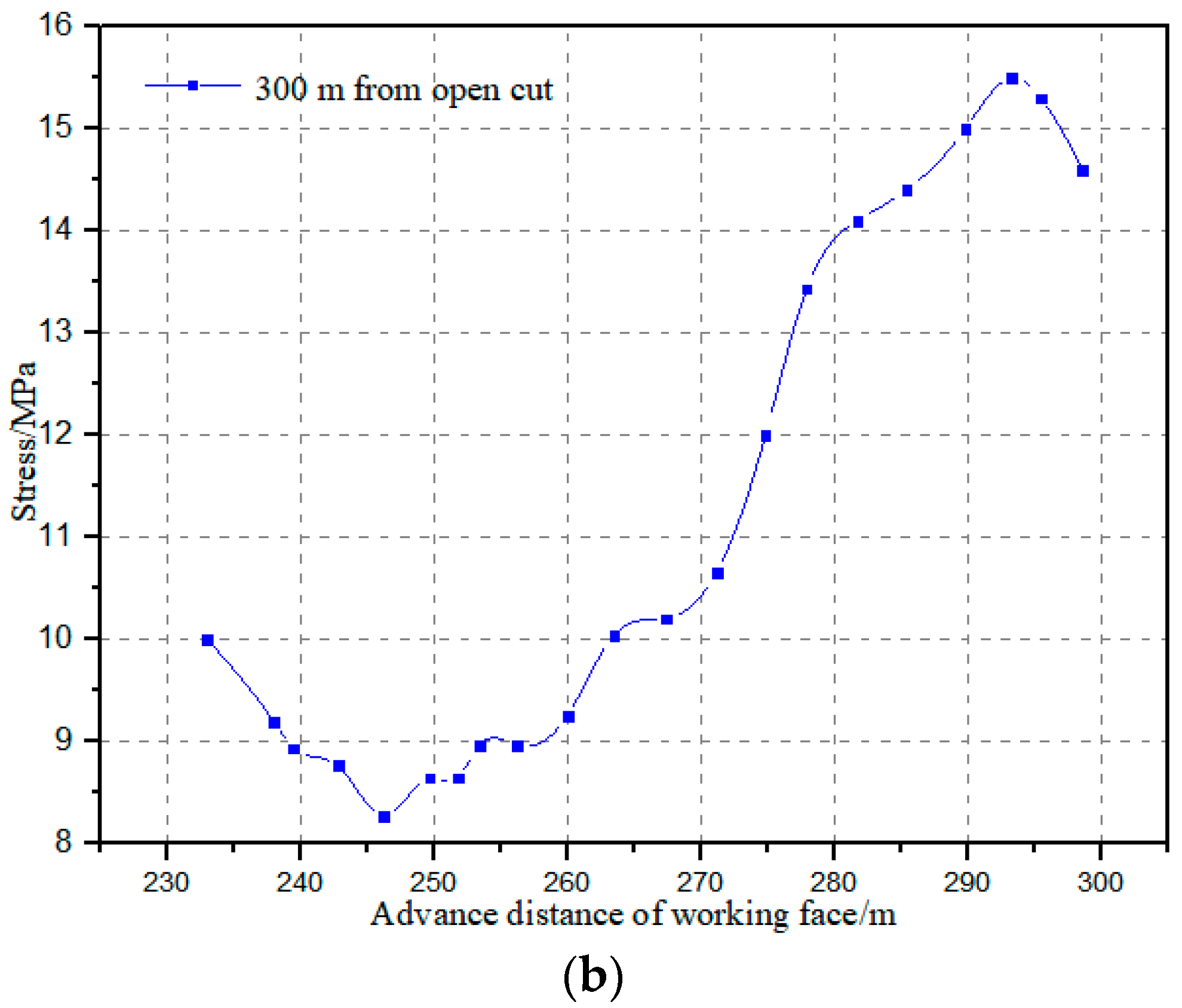
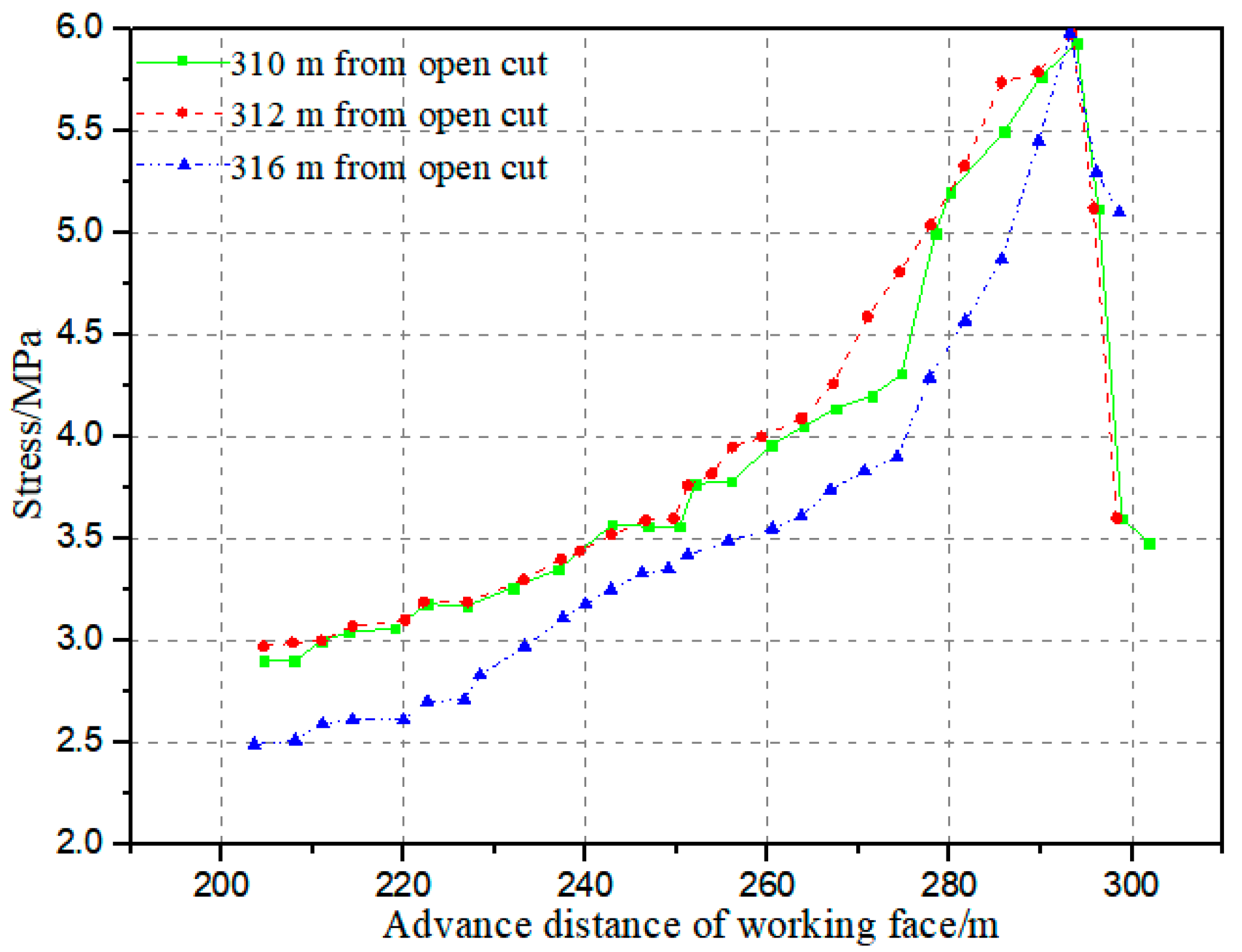
4.2.4. Distribution of Advanced Abutment Pressure
4.2.5. Detection of Fracture Morphology in the Coal Pillar
5. Discussion
6. Conclusions
- The large deformation of the rock surrounding a large section of mining roadway occurred due to the interaction of high stress, surrounding rock strength, and the support mode. The deformation of the rock surrounding the roadway presents obvious asymmetry and a strong rheological effect. Strong floor heave and two side movements are the main ground pressure characteristics of this kind of mining roadway.
- The original bolt mesh shotcrete support cannot effectively control the large deformation of the surrounding rock of a fully mechanized top-coal caving face in an extra-thick coal seam. The support body damage was mainly manifested as the breakage of the bolt cable and failure under the action of composite stress; sprayed concrete cracks and spalls under the action of local concentrated stress; and the I-beam, etc., was bent and deformed under the action of concentrated stress.
- The results from this study enable a suitable surrounding rock control in synergy scheme to be proposed, as well as parameters for coal pillar optimization–roof cutting destressing–grouting modification–rock bolting. Field experiments and observational information on surrounding rock deformation support the implementation of stress and grouting effects undertaken. The monitoring results indicate that, compared with the original surrounding rock control plan, the implementation of the surrounding rock control in a synergy scheme resulted in the anchoring effect of the anchor rod cable being fully exerted. The breaking rate was reduced by more than 90% and the deformation of the rock surrounding the roadway was reduced by about 70%. Field practice of the roadway surrounding rock control in the synergy method indicated that the rock deformation was effectively controlled, and the successful application of this technology was able to provide reliable technical and theoretical support for the Ningdong mining area and mines with similar conditions. These results have good promotional and application value.
Author Contributions
Funding
Data Availability Statement
Acknowledgments
Conflicts of Interest
References
- Duan, H.; Zhu, S.; Cao, S.; Zhang, M. Safe feasibility of retaining sand-proof coal rock pillars in full-mechanized caving mining of extra-thick coal seam. Arab. J. Geosci. 2021, 14, 778. [Google Scholar] [CrossRef]
- Kumar, R.; Mishra, A.K.; Kumar, A.; Singh, A.K.; Ram, S.; Singh, A.K.; Singh, R. Importance of fracturing hard and massive overlying strata for complete extraction of thick coal seam-case studies. J. Geol. Soc. India 2022, 98, 203–210. [Google Scholar] [CrossRef]
- Singh, R. Staggered development of a thick coal seam for full height working in a single lift by the blasting gallery method. Int. J. Rock Mech. Min. Sci. 2004, 41, 745–759. [Google Scholar] [CrossRef]
- Yan, S.H. Theory study on the load on support of long wall with top coal caving with great mining height in extra thick coal seam. J. China Coal Soc. 2009, 34, 590–593. [Google Scholar]
- Wang, J.; Liu, F.; Wang, Z. Experimental investigation on the movement mechanism of top coal in steeply inclined ultra-thick coal seams. Acta Mech. Sin. 2021, 37, 631–648. [Google Scholar] [CrossRef]
- Mangal, A. A study of stability investigation of immediate roof for extraction of thick coal seam in India. J. Inst. Eng. Ser. D 2021, 102, 203–221. [Google Scholar] [CrossRef]
- Marian, D.P.; Onica, I. Analysis of the geomechanical phenomena that led to the appearance of sinkholes at the lupeni mine, Romania, in the conditions of thick coal seams mining with longwall top coal caving. Sustainability 2021, 13, 6449. [Google Scholar] [CrossRef]
- Lv, H.; Cheng, Z.; Liu, F. Study on the mechanism of a new fully mechanical mining method for extremely thick coal seam. Int. J. Rock Mech. Min. Sci. 2021, 142, 104788. [Google Scholar] [CrossRef]
- Zha, W.; Shi, H.; Liu, S.; Kang, C. Surrounding rock control of gob-side entry driving with narrow coal pillar and roadway side sealing technology in Yangliu coal mine. Int. J. Min. Sci. Technol. 2017, 27, 819–823. [Google Scholar] [CrossRef]
- Barron, K. Analytical approach to the design of coal pillars. Int. J. Rock Mech. Min. Sci. Geomech. Abstr. 1985, 22, A84. [Google Scholar] [CrossRef]
- Corkum, A.G.; Board, M.P. Numerical analysis of longwall mining layout for a Wyoming Trona mine. Int. J. Rock Mech. Min. Sci. 2016, 89, 94–108. [Google Scholar] [CrossRef]
- Zhang, J.-F.; Liu, X.; Liu, Y.; Shao, X.-P.; Zhang, H.-M. Study of top coal partition and key delayed-action region for horizontal sublevel top coal caving in deeply inclined seam. Math. Probl. Eng. 2021, 2021, 8837678. [Google Scholar] [CrossRef]
- Wang, Q.; He, M.; Li, S.; Jiang, Z.; Wang, Y.; Qin, Q.; Jiang, B. Comparative study of model tests on automatically formed roadway and gob-side entry driving in deep coal mines. Int. J. Min. Sci. Technol. 2021, 31, 591–601. [Google Scholar] [CrossRef]
- Zhou, L.; Huang, Y.; Shao, Z.; Ma, F.; Zhang, P.; Wang, Y. Research on surrounding rock rheological effect and control method of large section chamber group in deep well. Geotech. Geol. Eng. 2021, 39, 5041–5061. [Google Scholar] [CrossRef]
- Jangara, H.; Ozturk, C.A. Longwall top coal caving design for thick coal seam in very poor strength surrounding strata. Int. J. Coal Sci. Technol. 2021, 8, 641–658. [Google Scholar] [CrossRef]
- Wu, C.; Qin, T.; Wang, L.; Liu, Z. Research on surrounding rock control technology of Dongbaowei deep mining roadway. Adv. Civ. Eng. 2021, 2021, 6660989. [Google Scholar]
- Roy, P.P. Emerging trends in drilling and blasting technology concerns and commitments. Arab. J. Geosci. 2021, 14, 652. [Google Scholar]
- Malan, D.F. Simulating the time-dependent behaviour of excavations in hard rock. Rock Mech. Rock Eng. 2002, 35, 225–254. [Google Scholar] [CrossRef]
- Hill, R. Continuum micro-mechanics of elastoplastic polycrystals. J. Mech. Phys. Solids 1965, 13, 89–101. [Google Scholar] [CrossRef]
- Carranza, T.C. Analytical and numerical study of the mechanics of rockbolt reinforcement around tunnels in rock masses. Rock Mech. Rock Eng. 2009, 42, 175–228. [Google Scholar] [CrossRef]
- Barton, N.; Grimstad, E. Rock mass conditions dictate choice between NMT and NATM. Int. J. Rock Mech. Min. Sci. Geomech. Abstr. 1995, 32, A135. [Google Scholar]
- Zelanko, J.C.; Mark, C. Reducing roof fall accidents on retreat mining sections. Coal Age 2005, 110, 26–31. [Google Scholar]
- Shiromizu, T.; Fujii, S.; de Rham, C.; Yoshino, H. High-energy effective theory for orbifold branes. Phys. Rev. D Part. Fields 2006, 73, 192–194. [Google Scholar] [CrossRef] [Green Version]
- Ying, Z.; Wang, H.; Amp, Z.D. Numerical analysis on surrounding rock support structural characteristics of deep soft rock roadway. Zhongzhou Coal 2014, 3, 4–7. [Google Scholar]
- Gao, R.; Yu, B.; Meng, X.B. Stress distribution and surrounding rock control of mining near to the overlying coal pillar in the working face. Int. J. Min. Sci. Technol. 2019, 29, 70–76. [Google Scholar] [CrossRef]
- Sun, C.; Hui, X.M.N.; Jia, B.X.; Zhang, T. Analysis of the stability of support system of large section tunnel in soft and weak surrounding rock. J. Disaster Prev. Mitig. Eng. 2015, 35, 359–364. [Google Scholar]
- Zhou, X.M.; Wang, S.; Li, X.L. Research on theory and technology of floor heave control in semicoal rock roadway: Taking longhu coal mine in Qitaihe mining area as an Example. Lithosphere 2022, 2022, 3810988. [Google Scholar] [CrossRef]
- Liu, H.Y.; Zhang, B.Y.; Li, X.L. Research on roof damage mechanism and control technology of gob-side entry retaining under close distance gob. Eng. Fail. Anal. 2022, 138, 106331. [Google Scholar] [CrossRef]
- Tang, B. Application of the maximum stress theory and roadway support practice in Australian collierie, Theory and Technique of Coal Mining and Disaster Prevention in Deep Mines. In Proceedings of the International Mining Conference, Shenzhen, China, 14–17 December 2014; pp. 157–160. [Google Scholar]
- Mcgarr, A. Some constraints on levels of shear stress in the crust from observations and theory. J. Geophys. Res. Solid Earth 1980, 85, 6231–6238. [Google Scholar] [CrossRef]
- Convertino, A.D.; Helm, J.L.; Pennesi, J.-L.; Gonzales, M.; Blashill, A.J. Integrating minority stress theory and tripartite influence model: A model of eating disordered behavior in sexual minority young adults. Appetite 2021, 163, 105204. [Google Scholar] [CrossRef]
- Xu, W.; Guo, Q. Axial analysis and block stability of surrounding rock of fractured rock mass based on unwedge. Metal Mine 2017, 8, 63–68. [Google Scholar]
- Chu, C.; Tong, G. Elastic-plastic stability of shear-deformable circular arches. J. Constr. Steel Res. 2021, 182, 106694. [Google Scholar] [CrossRef]
- Wang, S.; Li, X.L.; Qin, Q.Z. Study on surrounding rock control and support stability of Ultra-large height mining face. Energies 2022, 15, 6811. [Google Scholar] [CrossRef]
- Li, X.L.; Chen, S.J.; Wang, S. Study on in situ stress distribution law of the deep mine taking Linyi Mining area as an example. Adv. Mater. Sci. Eng. 2021, 9, 5594181. [Google Scholar] [CrossRef]
- Polovinkina, M.V.; Debbouche, A.; Polovinkin, I.P.; David, S.A. Stability of stationary solutions for the glioma growth equations with radial or axial symmetries. Math. Methods Appl. Sci. 2021, 44, 12021–12034. [Google Scholar] [CrossRef]
- He, M.C. Progress and challenges of soft rock engineering in depth. J. China Coal Soc. 2014, 39, 1409–1417. [Google Scholar]
- Kang, H.P. Sixty years development and prospects of rock bolting technology for underground coal mine roadway in China. J. China Univ. Min. Technol. 2016, 45, 1071–1081. [Google Scholar]
- Kang, H.P.; Jiang, P.F.; Huang, B.X.; Guan, X.M.; Wang, Z.G.; Wu, Y.Z.; Gao, F.Q.; Yang, J.W.; Cheng, L.X.; Zheng, Y.F.; et al. Roadway strata control technology by means of bolting-modification destressing in synergy in 1000 m deep coal mines. J. China Coal Soc. 2020, 45, 845–864. [Google Scholar]
- Ma, N.J.; Li, J.; Zhao, Z.Q. Study on the distribution law of partial stress field and plastic zone in surrounding rock of circular roadway. J. China Univ. Min. Technol. 2015, 44, 206–213. [Google Scholar]
- Liu, Q.S.; Lu, C.B.; Liu, B.; Liu, X.W. Study on seriflux diffusion mechanism and application of grouting reinforcement in deep roadway. J. Min. Saf. Eng. 2014, 31, 333–339. [Google Scholar]
- Bai, J.B.; Hou, C.J. Study on control principle and application of surrounding rock in deep roadway. J. China Univ. Min. Technol. 2006, 35, 145–148. [Google Scholar]
- Gou, P.F.; Xin, Y.J.; Shen, Y.M.; Zhang, H. Stability analysis and mechanism of two-side anchorage body in deep mine gateway. J. Min. Saf. Eng. 2013, 30, 7–13. [Google Scholar]
- Jiang, Y.D.; Wang, H.W.; Zhao, Y.X. Study on complementary control support technology of mining roadway in extremely soft rock. J. Rock Mech. Eng. 2009, 28, 2383–2390. [Google Scholar]
- Zhang, B.; Tian, S.C. Study on roof structure evolution process and surrounding rock control technology of gob-side roadway. Coal Sci. Technol. 2019, 47, 68–75. [Google Scholar]
- Geng, J.Y.; Wang, F.T.; Zhang, Y.; Ban, J.G.; Li, G. Research on key control technology of surrounding rock in high stress roadway. Coal Sci. Technol. 2019, 47, 189–196. [Google Scholar]
- Song, Z.Q. Basic law of overlying strata movement in stope. J. Shandong Univ. Sci. Technol. (Nat. Sci.) 1979, 1, 12–25. [Google Scholar]
- Liu, S.; Li, X.; Wang, D.; Zhang, D. Investigations on the mechanism of the microstructural evolution of different coal ranks under liquid nitrogen cold soaking. Energy Sources Part A—Recovery Util. Environ. Eff. 2020, 1–17. [Google Scholar] [CrossRef]
- Zhang, C.; Wang, E.; Li, B. Laboratory experiments of CO2-enhanced coalbed methane recovery considering CO2 sequestration in a coal seam. Energy 2023, 262, 125473. [Google Scholar] [CrossRef]
- Brueckner, M.; Spencer, R.; Knowles, S.; Paull, M. Mining legacies-broadening understandings of mining impacts. Extr. Ind. Soc. 2021, 8, 100950. [Google Scholar] [CrossRef]
- Tang, W.; Zhai, C.; Xu, J.; Yu, X.; Sun, Y.; Cong, Y.; Zheng, Y.; Zhu, X. Numerical simulation of expansion process of soundless cracking demolition agents by coupling finite difference and discrete element methods. Comput. Geotech. 2022, 146, 104699. [Google Scholar] [CrossRef]
- Tang, W.; Zhai, C.; Xu, J.; Sun, Y.; Cong, Y.; Zheng, Y. The influence of borehole arrangement of soundless cracking demolition agents (SCDAs) on weakening the hard rock. Int. J. Min. Sci. Technol. 2021, 31, 197–207. [Google Scholar] [CrossRef]
- Das, A.J.; Mandal, P.K.; Sahu, S.P.; Kushwaha, A.; Bhattacharjee, R.; Tewari, S. Evaluation of the effect of fault on the stability of underground workings of coal mine through DEM and statistical analysis. J. Geol. Soc. India 2018, 92, 732–742. [Google Scholar] [CrossRef]
- Shan, R.; Li, Z.; Wang, C.; Wei, Y.; Bai, Y.; Zhao, Y.; Tong, X. Research on the mechanism of asymmetric deformation and stability control of near-fault roadway under the influence of mining. Eng. Fail. Anal. 2021, 127, 105492. [Google Scholar] [CrossRef]
- Mazurek, K.; Szyguła, M.; Figiel, A.; Filipowicz, K. Continuous support for roadways. Energies 2021, 14, 5801. [Google Scholar] [CrossRef]
- Arjang, B. Effects of backfill in controlling pillar failure characteristics: An experimental study. In Proceedings of the 2nd North American Rock Mechanics Symposium, Montreal, QC, Canada, 19–21 June 1996; pp. 19–21. [Google Scholar]
- Tang, J.Q. Study on Rock Burst Mechanism and Control Strategies Based on Hard Roof; China University of Mining & Technology: Beijing, China, 2016. [Google Scholar]
- Pati, N.K. Evaluation of Underground Coal Pillar Design. Ph.D. Thesis, Department of Mining Engineering National Institute of Technology Rourkela, Sundargarh, India, 2011. [Google Scholar]
- Wiesław, G.; Stolecki, L. Deformation characteristics of a technological pillar in the chamber-pillar mining system. Arch. Min. Sci. 2014, 59, 323–335. [Google Scholar]
- Merwe, V.D.; Nielen, J. The role of overburden integrity in pillar failure. In Proceedings of the Second International Workshop on Coal Pillar Mechanics and Design, Vail, CO, USA, 6 June 1999. [Google Scholar]
- Coggan, J.; Gao, F.; Stead, D.; Elmo, D. Numerical modelling of the effects of weak immediate roof lithology on coal mine roadway stability. Int. J. Coal Geol. 2012, 90, 100–109. [Google Scholar] [CrossRef]
- Kang, H.P. Research and practice of bolting support technology in deep coal roadways. J. Min. Strat. Control. Eng. 2008, 13, 1–5. [Google Scholar]
- Li, J.G. Research on Coal Pillar Width and Support Optimization of Roadway Driving along Goaf in Extra-Thick Coal Seam; Inner Mongolia University of Science & Technology: Baotou, China, 2020. [Google Scholar]
- Malkowski, P.; Niedbalski, Z.; Majcherczyk, T.; Bednarek, L. Underground monitoring as the best way of roadways support design validation in a long time period. Min. Miner. Depos. 2020, 14, 1–14. [Google Scholar] [CrossRef]
- Zhang, D.F.; Zhang, Q.L.; Zhang, H.W. Study on surrounding rock control technology for mining roadway in ultra-deep protective layer. Coal Sci. Technol. 2021, 49, 45–51. [Google Scholar]
- Yang, K.; Gou, P. Research on reasonable width of coal pillars in high strength mining roadway in Wantugou mine. Geotech. Geol. Eng. 2020, 39, 2065–2073. [Google Scholar] [CrossRef]
- Fan, N.; Wang, J.; Zhang, B.; Liu, D.; Wang, R. Reasonable width of segment pillar of fully-mechanized caving face in inclined extra-thick coal seam. Geotech. Geol. Eng. 2020, 38, 4189–4200. [Google Scholar] [CrossRef]


| Lithology | Thickness (m) | Remarks | Lithology Description |
|---|---|---|---|
| Siltstone | 10.4 | Main floor | Griseous, silty structure, block structure |
| Coarse sandstone | 39.27 | Overlying strata | Gray-white, medium-particle structure, block structure, poor sorting |
| 1# coal seam | 0.92 | Overlying strata | Black, lump, dark briquette, Eye-shaped fracture |
| Fine sandstone | 4.96 | Main roof | Black-gray, mainly composed of quartz |
| Medium sandstone | 12.7 | Main roof | Gray-white, mainly composed of feldspar minerals and mud debris |
| Fine sandstone | 3.23 | Immediate roof | Gray, dark gray, mainly composed of feldspar minerals and mud debris |
| Siltstone | 4.62 | Immediate roof | Charcoal gray, upper intercalated with thin sandstone |
| Carbon mudstone | 0.4 | False roof | Black, containing a small amount of siltstone and pyrite |
| 2# coal seam | 9 | Coal seam | Black, lumpy |
| Lithology | Tensile Strength/MPa | Elastic Modulus/MPa | Poisson Ratio/MPa | Cohesion/MPa | Angle of Internal Friction/° |
|---|---|---|---|---|---|
| Siltstone | 4.52 | 14.6 | 0.2 | 4.66 | 32 |
| Medium sandstone | 3.86 | 14.4 | 0.23 | 4.83 | 26 |
| Fine sandstone | 5.1 | 7.52 | 0.225 | 1.7 | 28 |
| Siltstone | 3.57 | 12.5 | 0.2 | 4.27 | 30 |
| Carbon mudston | 1.7 | 10.75 | 0.21 | 1 | 23.8 |
| 2# coal seam | 1.3 | 1.86 | 0.26 | 0.75 | 30 |
Publisher’s Note: MDPI stays neutral with regard to jurisdictional claims in published maps and institutional affiliations. |
© 2022 by the authors. Licensee MDPI, Basel, Switzerland. This article is an open access article distributed under the terms and conditions of the Creative Commons Attribution (CC BY) license (https://creativecommons.org/licenses/by/4.0/).
Share and Cite
Hao, J.; Chen, A.; Li, X.; Bian, H.; Zhou, G.; Wu, Z.; Peng, L.; Tang, J. Analysis of Surrounding Rock Control Technology and Its Application on a Dynamic Pressure Roadway in a Thick Coal Seam. Energies 2022, 15, 9040. https://doi.org/10.3390/en15239040
Hao J, Chen A, Li X, Bian H, Zhou G, Wu Z, Peng L, Tang J. Analysis of Surrounding Rock Control Technology and Its Application on a Dynamic Pressure Roadway in a Thick Coal Seam. Energies. 2022; 15(23):9040. https://doi.org/10.3390/en15239040
Chicago/Turabian StyleHao, Jian, Anfa Chen, Xuelong Li, Hua Bian, Guanghua Zhou, Zhenguo Wu, Linjun Peng, and Jianquan Tang. 2022. "Analysis of Surrounding Rock Control Technology and Its Application on a Dynamic Pressure Roadway in a Thick Coal Seam" Energies 15, no. 23: 9040. https://doi.org/10.3390/en15239040