Article

Analysis of the Effects of Grid-Connected Charging/Discharging Stations on Relay Protection

1
School of Electrical and Electronic Engineering, North China Electric Power University, Beijing 102206, China
2
School of Electrical Engineering and Automation, Wuhan University, Wuhan 430072, China
3
Institute of New Energy, Wuhan 430202, China
*
Author to whom correspondence should be addressed.
Energies 2022, 15(23), 9065; https://doi.org/10.3390/en15239065
Submission received: 12 October 2022 / Revised: 17 November 2022 / Accepted: 25 November 2022 / Published: 30 November 2022

Abstract

:
The grid-connected operation of charging/discharging stations changes the original load, power supply, and network structures of the distribution network. It also affects the power flow level and direction and leads to a reduction in the sensitivity and reliability of the relay protection system. The grid connections may even lead to improper operation or failure of the relay protection protocols. In order to solve the above problems, this paper proposes a method that constructs the protection criteria by using the characteristics of the positive sequence comprehensive impedance after internal and external faults. Specifically, based on the difference in amplitude of the differential positive sequence impedance in the feeder after the charging/discharging station is connected to the grid, positive sequence comprehensive impedance is proposed for the purpose of establishing longitudinal differential protection. The results show that the vertical protection principle based on the positive sequence comprehensive impedance has a certain versatility for the protection of distribution networks with charging/discharging stations. Additionally, the protection principle has high sensitivity and is generally unaffected by transition resistance. The applicability of the proposed positive sequence comprehensive impedance vertical protection principle is verified by simulation.

1. Introduction

As a low-carbon economy has become the main tone of China’s economic development, electric vehicles, as an important part of the new energy strategy and the development of a new power system [1], are one of the important measures to reduce fuel consumption and carbon dioxide emissions in China [2] and were officially listed as seven national strategic emerging industries in 2012. At the same time, China’s energy revolution and transportation electrification provide important opportunities for the development of electric vehicles [3]. However, the development of electric vehicles is an economic and social system project [4], which must be coordinated with related industries, among which the most critical link is the construction of charge and discharge stations and grid connection [5,6]
The traditional distribution network of 10 kV and below usually adopts the radiant power supply structure of a single power supply, and the protection mode of the distribution network is mainly three-stage current protection, namely instantaneous current break protection, time-limited current break protection, and fixed time overcurrent protection [7]. The most common faults in distribution network operation are various types of short-circuit faults, such as single-phase grounding short-circuits, two-phase grounding short-circuits and three-phase short-circuits. Different from traditional power loads, EV charging loads in charging and discharging stations are characterized by randomness, nonlinear, and volatility [4]. After being connected to the power grid, the fault characteristics of its distribution network are easily affected by the topological structure, thus affecting the selectivity and sensitivity of relay protection in the distribution network. In addition, the access to large-capacity charge–discharge stations will also be accompanied by access to a large number of power electronic components, which have typical complex nonlinear characteristics, resulting in the fault current no longer being determined by transient voltage and reactance. Especially when asymmetric faults occur, the change in fault component and coupling relationship will further increase the difficulty of fault characteristic analysis. It brings great challenges to the stability of relay protection of the distribution network.
At present, there is a lot of literature on the impact of EVC (electric vehicle charging station) connection on the relay protection of distribution networks. For example, literature [8] proposed a protection scheme for electric vehicle charging and discharging stations, which mainly adopted the traditional current break protection mode, but the protective effect was not satisfactory because the transient process of fault was not considered. According to the charge–discharge characteristics of electric vehicles, the literature [8] regards electric vehicles in the discharge process as random loads and analyzes the impact of electric vehicles on the protection of distribution networks. This study has a certain complexity. The literature [9] proposes a protection scheme that uses the negative sequence components of voltage and current to determine the fault direction, this method needs to increase the voltage transformer and wiring complex, which is a high investment. The literature [10] proposes a fault-related region division method with strong adaptability, which realizes the selectivity and rapidity of protection and reduces the laziness of the communication system, but the bandwidth occupation rate of the communication system is high. The literature [11] proposed an adaptive scheme of distribution network distance protection including DG (distributed power supply), but it did not take into account the limitations of output current after the access of inverter distributed power supply. In view of the load characteristics of the charging load and its influence on the relay protection of the distribution network, the literature [4] proposes an overcurrent protection scheme based on the reactive power mutation and gives a detailed setting method and the action characteristics of the protection. This scheme can reduce the setting value of the protection and thus improve the sensitivity of the protection, and its overall performance is better than that of three-stage current protection. It has a certain novelty. In the literature [12], a fault current limiter is installed at the junction point of distributed power supply to reduce the impact on protection by improving the impedance and limiting the short circuit current at the junction point when a fault occurs. However, this approach will increase the cost and scheduling difficulty. According to the concept of wide-area protection, the literature [13] proposes a wide-area current differential protection system based on multi-agent, which has a good application prospect for the distribution network containing charge and discharge stations, but needs to improve the communication network. The above studies focus on increasing equipment input, changing the structure of the distribution network, or adjusting the protection value to solve the relay protection problem of the distribution network. However, the reliability of these protection schemes is still to be studied for the transmission protection of the distribution network in the case of line faults caused by the access of high-permeability and large-capacity charge-discharge stations.
In this paper, based on the access of large-capacity electric vehicle charging and discharging stations, from the perspective of the relay protection principle of distribution network, according to the charge-discharge characteristics of electric vehicles, the influence of charging and discharging station access on the protection direction components and positive sequence fault components of distribution network and the characteristics of positive sequence fault integrated impedance inside and outside the area are analyzed, and a new longitudinal protection method based on the comprehensive impedance of positive sequence fault components is proposed. It can correctly determine whether the fault location is in the zone or outside the zone. It cannot change the existing distribution network protection configuration, only need to make a simple software upgrade on the original protection device. The protection principle has good sensitivity and a certain ability to resist the transition resistance, which has a certain practicability for the protection of distribution networks with large capacity charging and discharging stations.

2. Analysis of Influence of Charging and Discharging Station Access on Relay Protection of Distribution Network

The charging load of new-energy electric vehicles is time-varying, non-linear, and harmonic [14]. When electric vehicles connect to the grid, the power demand is determined by the charging voltage and current, and the charging characteristics of different types of vehicles are different [15]. After the grid-connected operation of large-capacity charging and discharging stations, the charging load will fluctuate greatly due to the uncertainty of users’ car use needs and the differences in behavior habits, and it has certain complex characteristics of randomness, intermittence, and volatility in time and space. At the same time, the distribution network changes from a single-power radiant network to a double-terminal or multi-terminal network, and the magnitude, direction, and duration of short-circuit current change, resulting in the loss of sensitivity, rejection, misoperation, and other faults of the original distribution network relay protection [16].

2.1. Impact Analysis of Electric Vehicle Charging Load

Electric vehicles (EVs) have strong randomness and uncertainty in time and space. The influencing factors of EV charging load are mainly reflected in four aspects: (1) the characteristics of EVs are related, including the type of EVs, initial state of charge, development scale of EVs, power battery capacity of EVs, etc. (2) Unit power consumption, mainly including battery aging degree, battery life, battery energy management system efficiency, traffic conditions, weather conditions, etc. (3) User behavior, including charging time, charging method, travel rules, driving habits, charging frequency, charging location, etc. (4) Related to the supply mode, including the power level of the charging pile in the charging station, the power change mode of the charging pile, etc.

2.2. Analysis of Fault Characteristics

The access of large-capacity charging and discharging stations to the distribution network brings about the access of large-scale power electronic equipment, which changes the structure of the distribution network and makes the fault characteristics of the distribution network more complex [17,18,19,20]. When asymmetric faults occur in the distribution network system, the reactive power support capability of low-voltage crossing complicates the fault characteristics of grid-connected inverters in the charge-discharge station [21]. With an additional network connected to the distribution network [14] that has traditional relay protection based on fault components and fault characteristics under the asymmetric fault characteristics, correct fault direction determination and protection cannot be realized [22].
In addition, under the influence of power electronic equipment, the fault characteristics are not obvious and have certain coupling characteristics that are typical of asymmetric faults [23,24]. Due to the limitation of the system, the amplitude of the short-circuit current provided by the charging station will not be very large, nor will it be much larger than the load current under normal operating conditions. Therefore, in the distribution network connected to multiple charging stations, the effects of the load current cannot be ignored when analyzing the operation performance of feeder protection far from the side where the fault exists. At the same time that the connection of high-capacity charging and discharging stations to the distribution network will change the short-circuit capacity of nodes near the distribution network. After the connection of charging and discharging stations to the distribution network, the different types, capacity, installation location of protection and short-circuit fault location will affect the power flow distribution of the distribution network system and the short-circuit current when the fault occurs
Figure 1 shows a simplified distribution network with multiple charging and discharging stations. Each circuit breaker is equipped with a microcomputer relay protection device and is associated with a corresponding serial number (I = 1, 2, 3, 4, 5, 6). When the electric vehicle charging (EVC) system is connected to the distribution network, it has the characteristics of the load. Compared with a traditional load, the EVC system load will obviously exhibit randomness in time and space. The access of the EVC system changes the original power structure of the distribution network, converting the original single-source radiation network into a multisource complex network. The original magnitude and direction of the current of the distribution network will also be changed.
In addition, after EVC is connected to the distribution system, the original wiring mode is changed and the number of branches is increased, which makes the fault situation of the 10 kV distribution system complicated. Therefore, when the system short-circuit fault occurs, there will be a number of power supplies to provide short-circuit current, which disrupted the original relay protection configuration, affecting the reliability, selectivity, quick action, and sensitivity of the protection and reclosing device refuse and misoperation. As shown in Figure 1, when EVC2 of the charging station is connected to bus C and the fault occurs at F2, if EVC2 is not connected to the system, there is no current flowing on CB2 and F2 will not operate. However, when EVC2 is connected, the short-circuit current flowing through F2 will increase with the increase in capacity. When the capacity reaches a certain level, The current flowing through F2 will exceed its setting value, and F2 will trip, resulting in misoperation. When the EVC1 is connected to bus B and the fault occurs at F2, the current of CB2 will increase with the increase in EVC1 capacity. Although the current flowing through CB1 will decrease due to the shunt of EVC1 branch, the decrease will not exceed the increase in EVC1, which will eventually lead to the increase in the fault current flowing through F2. However, with the increase in the cut-off protection range of the timed current velocity of F2, the protection device may lose coordination with CB1, and the protection device will be unable to distinguish the short-circuit current generated by the charging station and the load current downstream of the protection, which will affect the selectivity and sensitivity of the protection device, and the protection device will not operate correctly. When the bus E near the protection CB6 is short-circuited, EVC3 and the large power grid simultaneously flow the short-circuit current to the short-circuit point, which will lead to the increase in the short-circuit current value of the protection CB5. When the capacity of EVC3 is very large, it is possible to make it exceed its setting value, resulting in protection misoperation.

2.3. Influence Analysis of Positive Sequence Fault Component

The application and adaptability of positive sequence fault components in distribution network protection systems are studied by analyzing the change in positive sequence fault components under the combined influence of voltage sag, power fluctuation, control, and other factors in distribution networks with charging/discharging stations.
a.
positive sequence fault component direction element
In the double-ended power supply linear system shown in Figure 2, the positive sequence fault component can be obtained by using the symmetric component method in composite sequence networks.
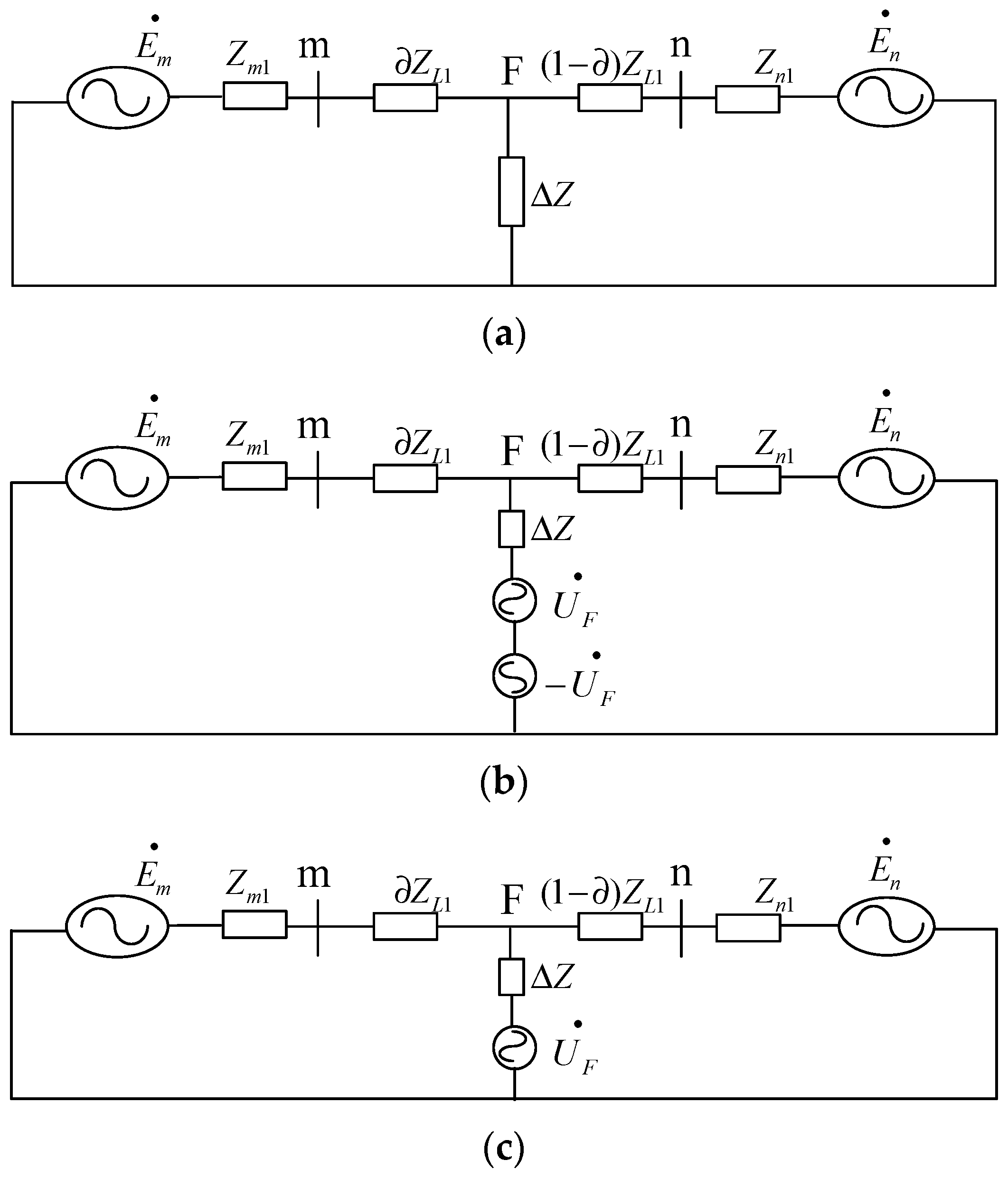
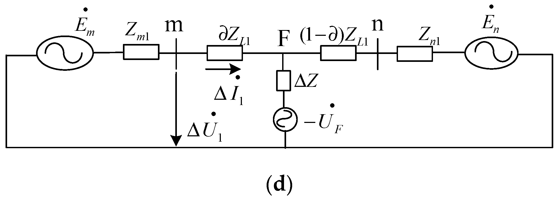
The positive sequence network faults in the occurrence area of line L is shown in Figure 3a. According to the principle of positive-order equivalence in the symmetric component method, ΔZ in the positive sequence fault component diagram represents the additional impedance, and its value depends on the type of fault. As shown in Table 1, if the fault occurs at point F, two additional power supplies can be connected in series in the additional impedance branch. In order to ensure the equivalence of the positive sequence network, the amplitude of the two power supplies should be equal but opposite (Figure 3b). According to the superposition theorem, the double-ended power systems can be decomposed into the pre-failure operating state and, additionally, the post-failure positive sequence fault component state as shown in Figure 3c and Figure 3d, respectively.
Figure 3d is taken as an example to analyze the positive sequence fault component. Where, the system parameters Zm1 and Zn1 are, respectively, the positive sequence impedance of the power supply on both sides, ZL1 is the positive sequence equivalent reactance of line L. Install directional elements on both sides of line L, The positive sequence fault component is calculated according to the system parameters. In the case of a fault at point F, it is a positive fault in the area for the protection installed on both sides. Then, the relationship between the fault component voltage and current of the m side protection direction element depends on the positive sequence impedance between the protection installation place and the m side far from the neutral point of the fault side system. The equation is as follows:
Δ U 1 = Δ I 1 Z m 1
In the case of a fault in the opposite direction, the relationship between voltage and current of the positive sequence fault components for protection on the m side is as follows:
Δ U 1 = Δ I 1 ( Z m 1 + Z L 1 )
Zm1 is the positive sequence impedance of the power supply; ZL1 is the positive sequence equivalent reactance of line L.
According to Equations (1) and (2), the action criterion of directional elements based on positive sequence fault components can be constructed as follows:
90 ° < arg Δ U 1 Z r Δ I 1 < 270 °
The action criterion for the reverse direction fault is as follows:
90 ° < arg Δ U 1 Z r Δ I 1 < 90 °
Zr is the simulated impedance.
b.
Effects of charging/discharging station connected to the grid on directional components
In the analysis of positive sequence fault components and directional fault components of grid-connected charging and discharging stations, the superposition theorem is no longer applicable because the fault characteristics of output short-circuit current is nonlinear, and a new method is needed to analyze and calculate the positive sequence fault components. In this paper, the voltage and current values of the installation position of the protection device after the failure minus the voltage and current state values before the failure. This method can solve the fault components under different fault types and different fault locations and analyze the variation law of the fault components.
In the case of transition resistance variation between phases, the non-fault phase positive sequence voltage component of the connecting point of the charging station also changes. In the case of a two-phase short-circuit fault, the phase component of the full voltage of the non-fault phase is inconsistent with the positive sequence component, and there is a phase difference [25,26], and the maximum phase Angle difference is obtained when the positive sequence voltage of the fault is tangent to the semicircle track. Therefore, the deviation of the positive sequence component at the grid connection of the charging station causes the phase deviation of the positive sequence fault component. Furthermore, the phase difference between the positive sequence component of the fault current and the positive sequence voltage is reduced. When large-capacity charging and discharging stations are connected, the variation law of phase difference is more complex, and the phase difference will exceed the positive fault identification range of directional elements, resulting in the failure of the normal operation of protection.

3. Relay Protection Scheme

When analyzing the faults of the grid connection of the charge–discharge station, the charge–discharge station can be equivalent to a voltage controlled current source only existing in the positive sequence additional network. It is known that the phase difference between the measured voltage and current on the protection side at both ends of the feeder will change under the fault condition, and the ratio of the fault component of the positive sequence voltage and current on the protection side can be defined as the positive sequence integrated impedance [27]. By comparing the positive sequence integrated impedance information on both sides of the feeders and the differences in the characteristics of faults in and out of the area, the longitudinal protection based on the positive sequence integrated impedance was proposed and its operational characteristics were analyzed.

3.1. Based on Fault Component Positive Sequence Integrated Impedance Protection Principle

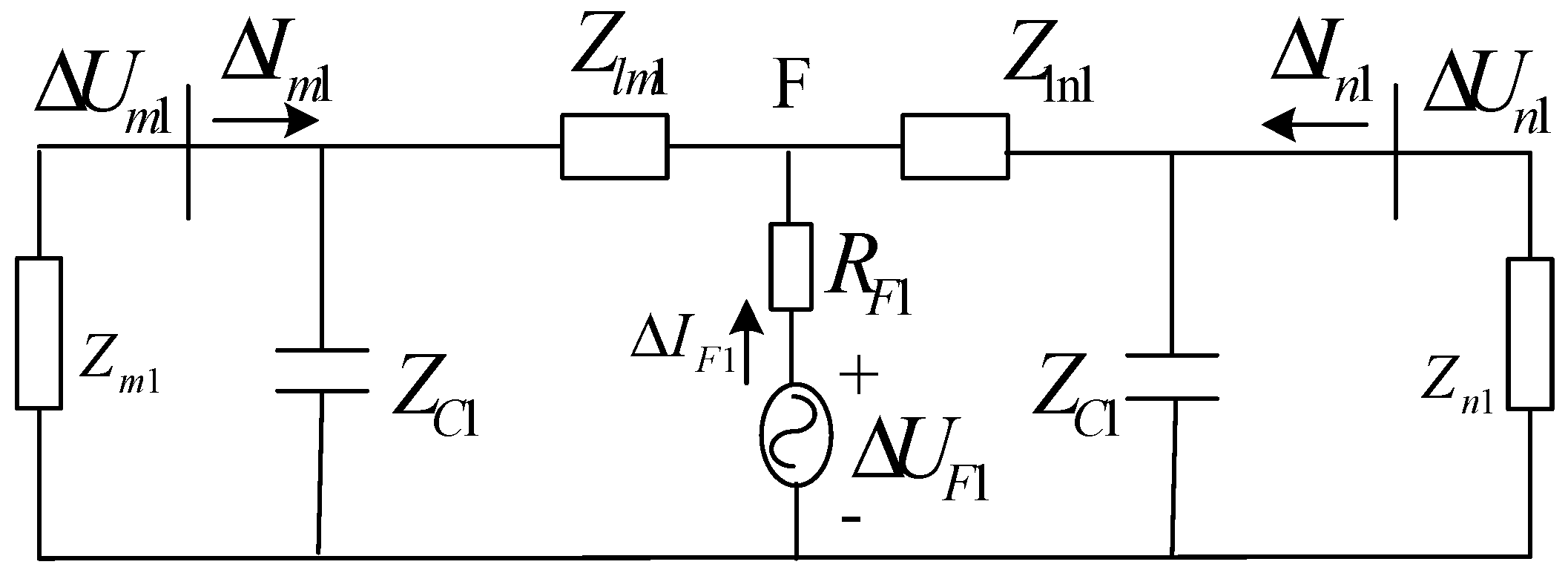
Figure 4 shows the positive sequence network diagram of the fault component when the fault occurs at point F of the two-sided power supply line. The line adopts the Π type equivalent circuit model. Z m 1 and Z n 1 are the impedances of a positive sequence power supply on both sides of the line. Z lm 1 and Z ln 1 are the positive sequence line impedances at both ends of the fault point; Z C 1 is the line positive sequence capacitive reactance; Δ U F 1 is the positive sequence fault component potential at point F; Δ I F 1 is the positive sequence current flowing through the fault branch; C is the positive sequence resistance at the fault point; Δ U m 1 , Δ U n 1 , Δ I m 1 and Δ I n 1 are the voltages and currents of positive sequence fault components at the m- and n-sides of the busbar, as indicated by the subscripts. The positive sequence integrated impedance of the fault component Δ Z c d 1 is defined as:
{ Δ Z c d 1 = Δ U c d 1 / Δ I c d 1 Δ U c d 1 = Δ U m 1 + Δ U n 1 Δ I c d 1 = Δ I m 1 + Δ I n 1

3.1.1. Positive Sequence Integrated Impedance of Fault Component in an Out-of-Zone Fault

For the two-terminal power supply linear system in Figure 2, if the fault occurs near the power supply side, it is an out-of-area fault for protection. Figure 5 shows the positive sequence network diagram of fault components when out-area faults occur on the line. In Figure 5, Δ I m C 1 and Δ I n C 1 are the positive sequence currents of fault components that flow through the two corresponding sequence capacitors of the lines.
The equation for the positive sequence differential current of fault components is as follows:
Δ I cd 1 = Δ I m 1 + Δ I n 1 = Δ I m C 1 + Δ I n C 1 = Δ U m 1 / Z C 1 + Δ U n 1 / Z C 1
The positive sequence comprehensive impedance equation for fault components is as follows:
Δ Z c d 1 = ( Δ U m 1 + Δ U n 1 ) / Δ I c d 1 = Z C 1
In other words, when an out-of-zone fault occurs on the line, the value of the positive sequence impedance is larger than that of the system and the line.

3.1.2. Positive Sequence Integrated Impedance of Fault Components in the In-Zone Fault

For the double-terminal power supply linear system in Figure 2, if a fault occurs within the feeder segment mn, namely point F, it is an in-area fault. When an in-area fault occurs, the capacitor component in the positive sequence differential current of the fault component is small, and the influence of capacitance is ignored. When an in-area fault occurs on the line, the positive sequence fault component network is shown in Figure 4. Z M 1 and Z N 1 are the impedances on both sides of the fault point. When equations Z M 1 = Z m 1 + Z l m 1 and Z N 1 = Z n 1 + Z ln 1 are true, the following equations are obtained:
Δ I F 1 = Δ U F 1 / ( R F 1 + Z M 1 / / Z N 1 )
Δ U m 1 = Δ I F 1 × Z N 1 Z M 1 + Z N 1 × Z m 1
Δ U n 1 = Δ I F 1 × Z M 1 Z M 1 + Z N 1 × Z n 1
Δ I c d 1 = Δ I m 1 + Δ I n 1 = Δ I F 1
If we substitute Δ U m 1 , Δ U n 1 and Δ I c d 1 into Equation (7), we know that
Δ Z c d 1 = Z N 1 Z m 1 + Z M 1 Z n 1 Z M 1 + Z N 1
Assume that the impedance angles Z M 1 , Z N 1 , Z m 1 and Z n 1 are approximately equal. Since Z m 1 < Z M 1 and Z n 1 < Z N 1 , if the value of Z m 1 in Formula (11) is Z M 1 and the value of Z n 1 is Z N 1 , the upper limit of Δ Z c d 1 can be obtained:
{ Δ Z c d 1 < 2 Z M 1 Z N 1 / ( Z M 1 + Z N 1 ) Δ Z c d 1 < 2 ( Z M 1 / / Z N 1 ) Δ Z c d 1 < min ( 2 Z M 1 , 2 Z N 1 )

3.1.3. Positive Sequence Integrated Impedance of Fault Component in the Fault Zone

As can be seen from the above analysis, when the out-area fault occurs ( Δ Z c d 1 = Z C 1 ), and when a fault occurs in the in-zone, Δ Z c d 1 reflects the positive sequence power supply impedance and line impedance, which is far less than the positive sequence reactance of the line. It can be used to determine whether there is a fault on the line. The principle of longitudinal protection based on the positive sequence integrated impedance of fault components is as follows:
{ | Δ Z cd 1 | < Z s e t 1 | Δ I c d 1 | > I s e t 1 Z s e t 1 = K r e l 1 Z C 1
where K r e l 1 is the reliability coefficient (0.5–0.6), and I s e t 1 is the value of the current (>0.2 IN).
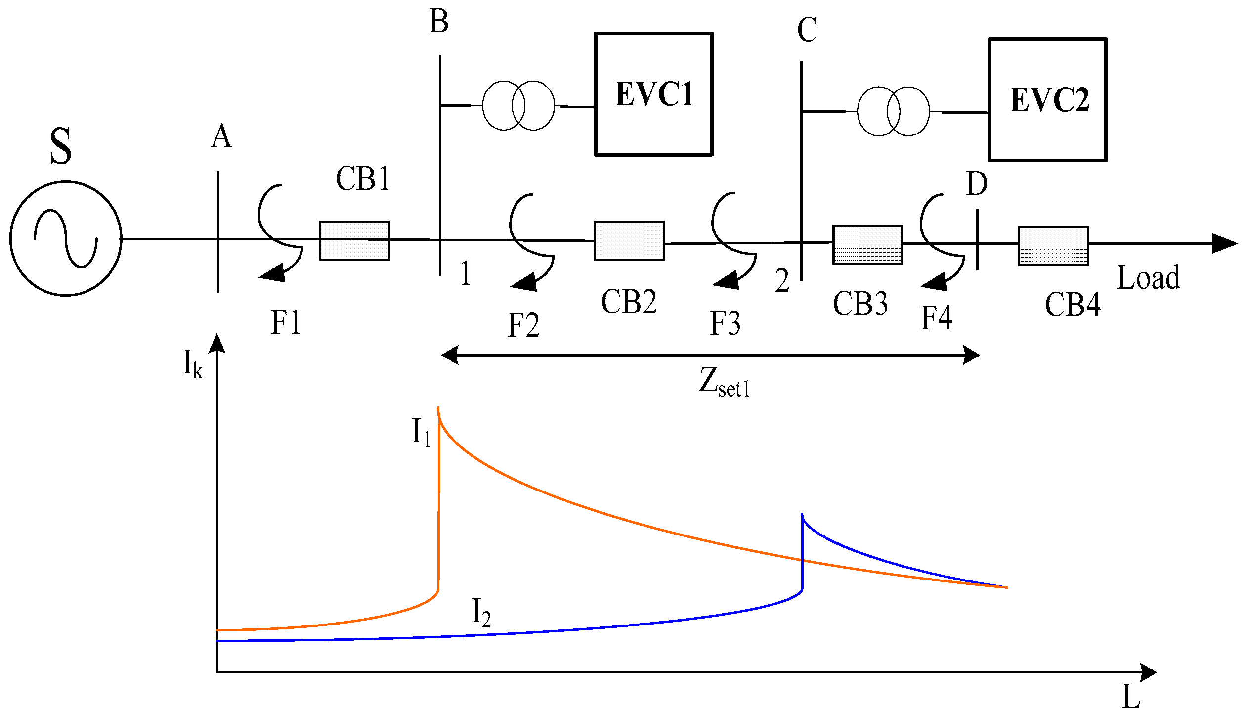
Figure 6 shows the setting diagram of three-phase short-circuit fault protection. When the charging and discharging station is connected to the grid, the current near the fault point of the three-phase short-circuit protection installation on the system side mainly comes from the short-circuit current provided by the power grid. It can be approximated as: In the case of fault, the amplitude of the measured positive sequence comprehensive impedance of protection at both ends is proportional to the distance length between fault points. Therefore, according to the fault characteristics of F2 when a three-phase short circuit occurs in Figure 6, the relationship between the set amplitude impedance of CB1 near the power supply side and the impedance of the protected line can be established as follows:
Z s e t 1 = k z r e l Z l B C
where k Z r e l is reliability coefficient of impedance.
Under this action criterion, if the measured impedance is within the range of BC line impedance, it indicates that the fault point is located in the BC feeder.
The advantage of this protection criterion is that when the three-phase short circuit occurs, the amplitude of the residual voltage vector is zero, and the measured value of positive sequence impedance is almost zero, it is still within the range of this criterion to ensure the reliable action of protection. However, in the feeder section BC upstream side of fault point F1 and the BC near the system protection such as the point F2 failure cases, the system voltage amplitude is larger, and the positive sequence impedance amplitude characteristics cannot accurately judge direction, there is no guarantee that the selectivity of protection action, however, is available at different fault current fault characteristics to distinguish the direction, In point F1 faults, the short circuit current is provided by the charging and discharging station, while in point F2 faults, the short circuit current is mainly provided by the power grid. The fault direction can be identified according to the positive sequence current amplitude characteristics.
In Figure 6, I1 and I2 are the variation curves of three-phase short-circuit current Ik flowing through system side protection 1 and inverter power side protection 2 with fault position L, respectively. When faults occur at different positions, the amplitude of short-circuit current changes obviously. In the case of point F1 and point F2 failure, If the curve I1 changes greatly, then the positive sequence current setting amplitude at the first protection 1 of BC is as follows:
I s e t 1 = k r e l I E V C 1 max
Under this condition, faults F1 and F2 at different fault locations can be distinguished, where I E V C 1 max is the maximum short-circuit current that can be provided to the fault point near the system power supply side at CB1 when all downstream charging and discharging stations are grid-connected, and the reliability coefficient ( k r e l > 1 ). Similarly, the positive sequence amplitude current of protection 2 is adjusted according to the amplitude characteristics of short circuit current at the installation of protection 2 in the feeder segment at different fault locations is adjusted as follows:
I s e t 2 = k i r e l I E V C 2 max
Under this setting condition, the faults inside and outside the zone F3 and F4 can be distinguished reliably. Type I E V C 2 max for all charge and discharge of the downstream in the parallel operation, to protect the two near the system power supply side of the fault point maximum short-circuit current, if the measured fault current is greater than the setting value, this means that the failure occurred in the CD feeder, the fault zone, then CB2 blocking signal and differential protection information, CB1 after receiving blocking signal protection, reliable locking action.
To sum up, the auxiliary protection criterion for three-phase short-circuit fault under grid-connected operation is composed of the protection action criterion on the side close to the system and the protection latching criterion on the side far away from the system. The specific forms are shown in Equations (18) and (19).
The protection action criterion equation of the power side near the grid is as follows:
{ | Z 1 + | | Z s e t 1 | I 1 + I s e t 1
Away from the power supply side protection lock conditions are as follows:
I 2 + I s e t 2
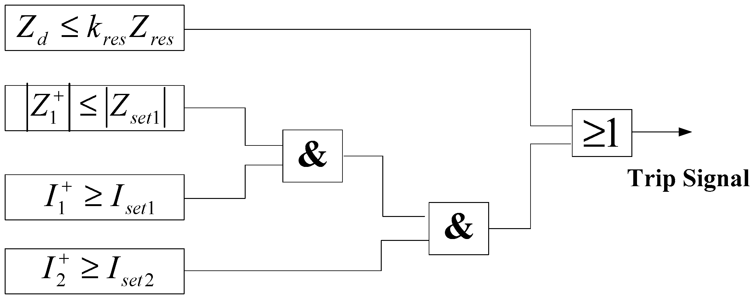
where I 1 + and I 2 + are the positive sequence currents flowing through protection 1 and 2 after the fault. Thus, the logic block diagram of vertical protection action based on positive sequence comprehensive impedance is shown in Figure 7.

3.2. Performance Analysis

In this paper, the principle of fault component positive sequence integrated impedance longitudinal protection does not require input capacitance parameters and compensating reactor parameters, nor does it need to compensate for the capacitance current. The guiding line current differential protection of medium- and short-distance transmission lines in medium- and low-voltage distribution networks has the characteristics of short lines and low-distributed capacitance current. When a fault occurs outside the zone, the system voltage decreases, the distributed capacitor current decreases further, the line current increases, and the value of | Z c d 1 | increases, all of which ensures proper operation when the fault occurs outside the zone. When a fault occurs in the area, and since Z s e t 1 is measured online, it can be concluded from the above analysis that | Z c d 1 | will certainly be less than Z s e t 1 . In order to further improve the reliability of the criterion, R F 1 can be made larger. Therefore, compared to the traditional current differential protection, the principle of fault component positive sequence integrated impedance longitudinal protection is unaffected by transition resistance in theory and can be used in the line with or without reactor compensation.
By analyzing the faults inside and outside the zone, the positive sequence comprehensive impedance characteristics under the fault condition can be obtained as follows:
(1)
The differential impedance of the positive sequence fault component is constructed by analyzing the different amplitudes of the sum of measured impedance of the protection at both ends of the feeder when the fault occurs inside and outside the zone: Z d = | Z 1 + + Z 2 + Z l 1 | .
(2)
The positive sequence integrated impedance can effectively determine the impedance of the internal fault of the line within the range of the vertical differential protection and is not affected by the fault of the grid-connected equipment.
(3)
The positive sequence comprehensive impedance depends on the voltage-to-current ratio of the positive sequence fault component after the fault occurs, and the calculated results are approximately the same at any time during the steady state period of the fault. Therefore, the protection elements at both ends of the feeder are not required to consider whether synchronous sampling and the data window are synchronized during differential protection, which is suitable for fault analysis and feeder protection under the grid-connected operation of large-scale charging and discharging stations.

4. Simulation Verification

4.1. Simulation Structure and Parameters

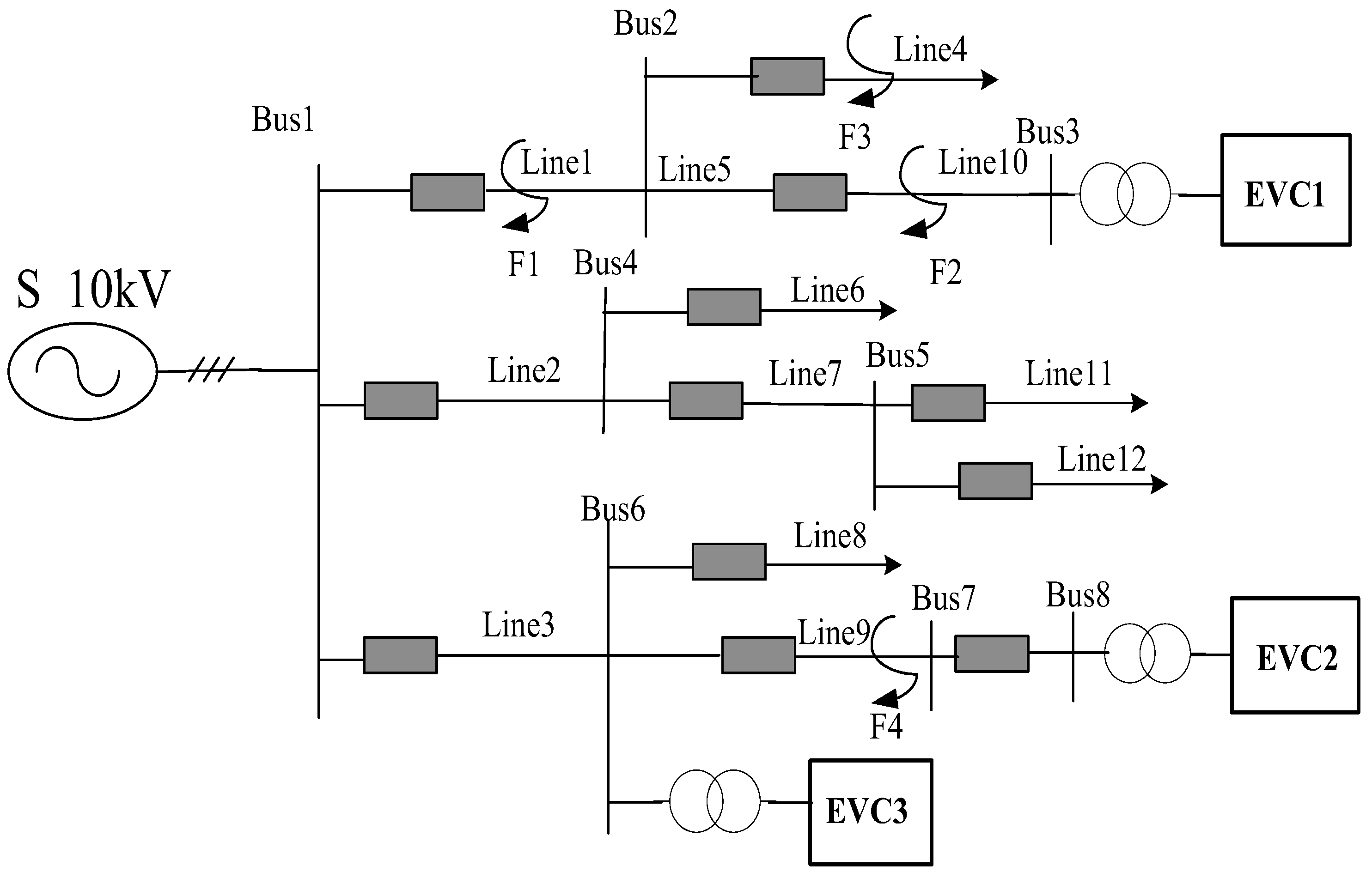
In order to verify the adaptability of the principle of longitudinal protection based on the positive sequence integrated impedance of fault components, a medium-voltage distribution network model diagram of 10 kV neutral grounding system via arc suppression coil was constructed in PSCAD, and the result is shown in Figure 8.
Figure 8 shows that line 10 does not have a branch feeder load whereas line 9 does, and the load proportion of the branch feeder is 38%. In the process of action prediction, the braking coefficient is 0.36, and the maximum value of the initial current in line 9 is 172 A under the condition of grid-connected operation. The power distribution capacity is 200 MVA, the transformer capacity is 4 MVA, the neutral point is grounded by a 0.8 MH arc elimination coil, and the line unit impedance is (0.16 + j0.32) Ω/km. The rated capacity of EVC1, EVC2, and EVC3 is 2.0, 3.5, and 2.0 MVA, respectively. The base load of 10 kV neutral point via arc suppression coil grounding system in medium voltage distribution network is other loads except the charging load of electric vehicles. In the simulation, the full-period Fourier filter algorithm is used to calculate and simulate various faults at the locations of F1, F2, F3 and F4.

4.2. Simulation Results

a.
Influence of charging station access on load of distribution network
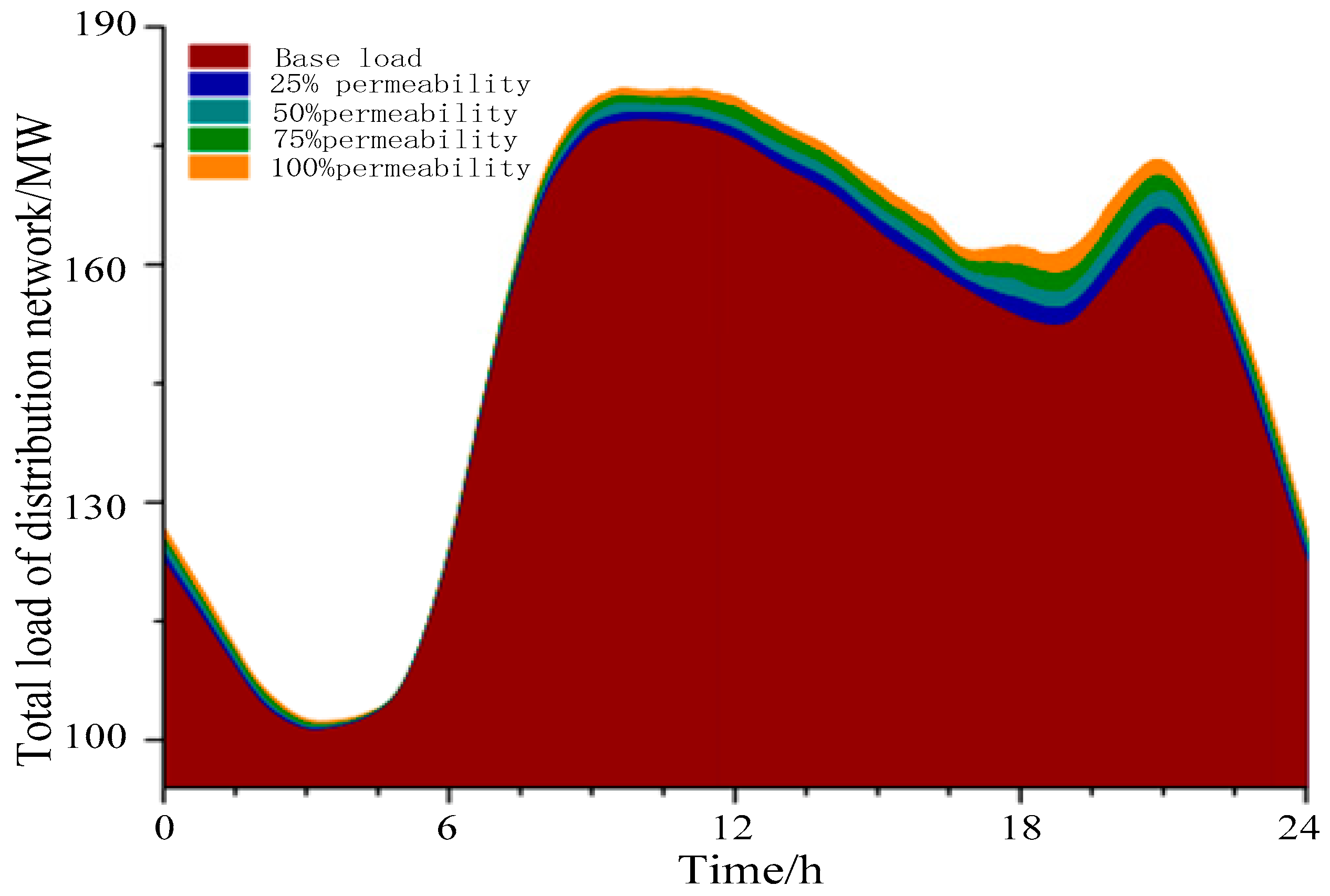
Based on the total load of the system, the daily load rate distribution of the typical daily load curve of a charging station in winter is adopted in this paper. The peak periods of the conventional load in the distribution network are distributed at 9:00 and 20:30. The typical daily load of distribution network is shown in Table 2.
Considering the randomness, volatility, and intermittency of the charging load when the charging station is connected to the 10 kV medium voltage distribution network, the influence of electric vehicle charging load on the distribution network is analyzed under the conditions of 0%, 25%, 50%, 75%, and 100% permeability. Figure 9 shows the total load of the distribution network under different permeability. As the permeability of electric vehicles increases, load superposition on the basis of the original peak load of the power network is caused. There was little impact during the night when the grid base load was low.
b.
Protection action result
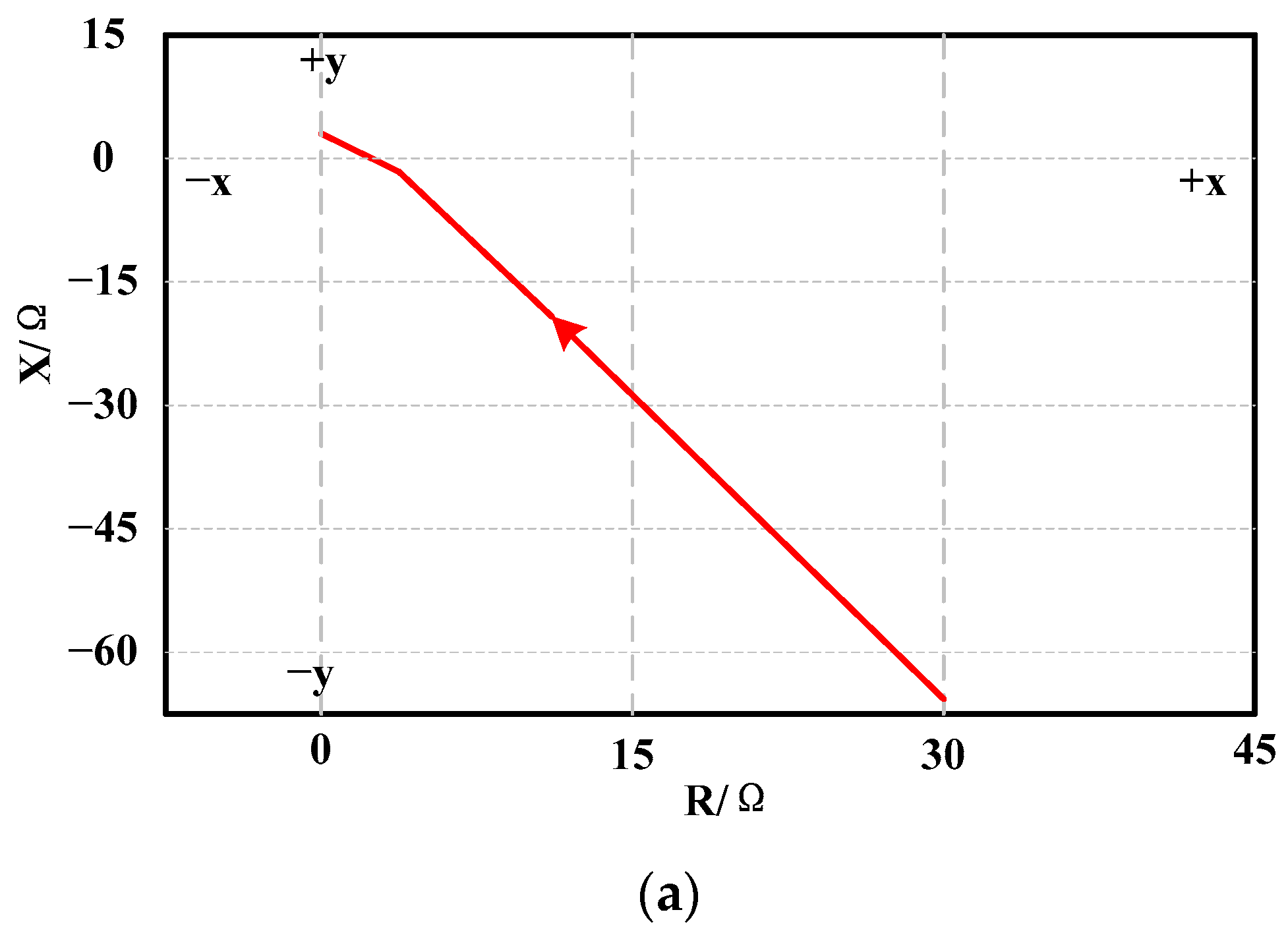
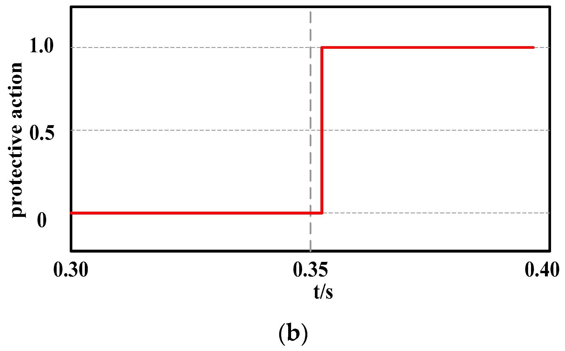
Figure 10 shows the comprehensive positive sequence impedance trace and protection action of three-phase ground fault at F1 of Line1. Before the fault, the measured impedance is outside the range of the operation. When the three-phase large transition resistance ground fault occurs on Line1 at 0.35 s, the transition resistance is 15.86ω. At this time, the measured impedance enters the protection area quickly and the protection moves quickly, as shown in Figure 10b. The results show that the vertical protection criterion based on the positive sequence integrated impedance of fault components can also meet the requirement of rapidity in the case of large transition resistance.
Considering feeder line 10 as an example for analysis, it is assumed that the system fails at 0.2 s and the simulation time is 0.5 s, the determination of the positive sequence integrated impedance differential protection at different positions and under different fault conditions is shown in Table 3.
Table 3 shows that when the feeder section near the side of the system fails to protect components downstream from the failure (for example, at F2 and F3 in the model), the charging/discharging station at the point of failure will provide part of the short-circuit current to protect the branch due to load current, and the downstream station will have little impact on the short-circuit current; charging and discharging can ignore this effect. If the fault location in a certain line reserves adjacent lines, such as F1 and F4 in the model, then with this kind of downstream protection, short-circuit current will be determined by the output current of the feeder charge and discharge of the downstream station. This is due to the greater complexity of the fault characteristics, in this case, considering load short-circuit current and its relationship with the fault current. Additionally, in this case, the phase angle value of the positive sequence impedance varies greatly. In case of a fault in the region, the phase difference of the positive sequence impedance on both sides of the feeder protection is small, and the braking impedance is approximately zero.
In addition, in order to study the effects of transition resistance on differential protection, the value of transition resistance can be changed to analyze the change in positive sequence integrated impedance and differential current after determining the fault type at a certain fault location. In Table 3, as the transition resistance Zf increases, the amplitude of the measured positive sequence impedance at the protection installation increases accordingly. Within a certain range, with the increase in the transition resistance, the differential impedance will gradually increase, and the phase angle difference between the positive sequence impedances of the protection on both sides of the feeder will gradually increase.
Furthermore, line 9 is further taken as an example to analyze the action criterion with different braking characteristics, and the results are shown in Table 4.
As can be seen from Table 4, if a fault occurs on the downstream side outside the feeder section, most of the short-circuit current flowing through the protection installation at both ends at this time originates from the system power supply. Since the amplitude of the positive sequence differential impedance is about zero, far less than the braking impedance, the protection does not take effect. If the fault occurs in the upstream or adjacent lines outside the feeder segment, the amplitude of the positive sequence differential impedance will increase due to the presence of branch load current. When the fault occurs in the zone, the positive sequence integrated impedance can ensure the protection operation requirements. When the fault occurs outside the zone, the positive sequence integrated impedance is much greater than the line impedance, which ensures the reliability of the protection based on the positive sequence integrated impedance.
It can be seen that when a charging station with a certain capacity is connected to the distribution network with a 10 kV neutral point grounded through the arc suppression coil, the load of the distribution network will be changed, and the relay protection of the distribution network will be affected. The impact is related to the capacity and access location of the charging and discharging station, as well as the type of system faults. With the increase in the capacity of the charging and discharging station, the auxiliary current of the relay protection increases, and the protection range may extend to the next level of the line, so that the protection will lose reliability. For charge and discharge stations in the upstream of relay protection, when a fault occurs, the system side of the power grid and charging and discharging station will provide fault current to the point of failure. For downstream line protection, through its current is increased, the charging and discharging station help increase, because of the existence of help increased current leads to the lower line fault occurs misoperation, lose protection selectivity. When the charging and discharging station is downstream of the protection, it has a shunt effect, the fault current flowing through the fault point decreases, the protection range becomes smaller, and the sensitivity of the protection decreases. Therefore, the positive sequence comprehensive impedance of fault components can be used to correctly determine whether the fault location is in the area or outside the area. The vertical protection principle based on the positive sequence comprehensive impedance can be applied to low-voltage distribution network lines with large-capacity charging and discharging stations. The protection principle has high sensitivity and is generally unaffected by transition resistance.

5. Conclusions

(1)
The large-capacity charging and discharging stations are connected to the distribution network, which changes the generation and fault characteristics of the short-circuit current. The original single-radiation power supply network will be changed to a double-terminal or multi-terminal network due to the access of large-capacity charging and discharging stations, which will bring many adverse effects to the relay protection device of the distribution network. The relay protection configuration of grid-connected charging and discharging stations not only needs to consider the fault characteristics of charging and discharging stations themselves but must also consider the effects on the fault characteristics of a distribution network.
(2)
This paper analyzes the short-circuit fault characteristics of charging and discharging stations connected to the grid. Different fault situations have different fault characteristics, and the impact on distribution network protection is also different, with focus on the analysis of the impact on the positive sequence fault components. Under the influence of fault characteristic analysis, the principle of the positive sequence integrated impedance longitudinal protection is proposed. Under different fault conditions, the amplitude characteristics of the positive sequence impedance inside and outside the zone, and the positive sequence impedance differential protection criterion with braking characteristics, are studied and analyzed.
(3)
By adding the effects of transition resistance to the protection criterion in the simulation and calculation process, the simulation results verify the applicability of the protection principle.
(4)
The research results show that the vertical protection principle based on positive sequence comprehensive impedance offers a certain practicality for the protection of distribution networks with large-capacity, charge–discharge stations. The protection principle has high sensitivity and is generally unaffected by transition resistance, which provides theoretical support for the improvement of grid-connection protection of large-capacity, charging/discharging stations.

Author Contributions

Conceptualization, Q.W. and J.M.; methodology, J.M.; validation, S.C. and L.S.; formal analysis, S.C.; investigation, L.S.; writing—original draft preparation, S.C.; writing—review and editing, Q.W., J.M., S.C. and L.S.; supervision, J.M. and L.S.; funding acquisition, J.M. and L.S.; All authors have read and agreed to the published version of the manuscript.

Funding

This work was supported by the National Natural Science Foundation of China (51822703).

Conflicts of Interest

The authors declare no conflict of interest.

References

  1. Fan, J.L.; Zhang, Y.J.; Wang, B. The impact of urbanization on residential energy consumption in China: An aggregated and disaggregated analysis. Renew. Sustain. Energy Rev. 2017, 75, 220–233. [Google Scholar] [CrossRef]
  2. Li, W.; Long, R.; Chen, H. Consumers’ evaluation of national new energy vehicle policy in China: An analysis based on a four paradigm model. Energy Policy 2016, 99, 33–41. [Google Scholar] [CrossRef]
  3. Li, Y.M.; Zhang, Q.; Liu, B.Y.; McLellan, B.; Gao, Y.; Tang, Y.Y. Substitution effect of New-Energy Vehicle Credit Program and Corporate Average Fuel Consumption Regulation for Green-Car Subsidy. Energy 2018, 152, 223–236. [Google Scholar] [CrossRef]
  4. Bradley, T.; Quinn, C. Analysis of plug-in hybrid electric vehicle utility factors. J. Power Sources 2010, 195, 5399–5408. [Google Scholar] [CrossRef]
  5. Thomas, C.E.S. Transportation options in a carbon constrained world: Hybrids, plug-in hybrids, biofuels, fuel electric vehicles, and battery electric vehicles. Int. J. Hydrogen Energy 2009, 34, 9279–9296. [Google Scholar] [CrossRef]
  6. Shuang, G.; Chau, K.T.; Chan, C.C.; Diyun, W. Loss Analysis of Vehicle-To-Grid Operation. In Proceedings of the 2010 IEEE Vehicle Power and Propulsion Conference, Lille, France, 1–3 September 2010; IEEE Computer Society: Washing, DC, USA, 2010; pp. 1–6. [Google Scholar]
  7. Jenkins, S.D.; Rossmaier, J.; Ferdowsi, M. Utilization and effect of plug-in hybrid electric vehicles in the united states power grid. In Proceedings of the IEEE Vehicle and Propulsion Conference (VPPC), Harbin, China, 3–5 September 2008. [Google Scholar]
  8. Staats, P.T.; Grady, W.M.; Arapostathis, A.; Thallam, R.S. A statistical analysis of the effect of electric vehicle battery charging on distribution system harmonic voltages. IEEE Trans Power Deliv. 2010, 13, 640–646. [Google Scholar] [CrossRef]
  9. Schlee, J.; Mousseau, A.; Eggebraaten, J.; Johnson, B.; Hess, H.; Johnson, B. The Effects of Plug-In Electric Vehicles on a Small Distribution Grid. In Proceedings of the 41st North American Power Symposium, Starkville, MS, USA, 4–6 October 2009; IEEE Computer Society: Washing, DC, USA, 2009; pp. 1–6. [Google Scholar]
  10. Kroposki, B.; Pink, C.; DeBlasio, R. Benefits of power electronic interfaces for distributed energy systems. IEEE Trans. Energy Convers. 2010, 25, 901–908. [Google Scholar] [CrossRef] [Green Version]
  11. Zhong, C.; Ming, D.; Jianhui, S. Modeling and control for large capacity battery energy storage system. In Proceedings of the 2011 4th International Conference on Electric Utility Deregulation and Restructuring and Power Technologies (DRPT), Weihai, China, 6–9 July 2011; pp. 1429–1436. [Google Scholar]
  12. Ma, J.; Li, J.; Wang, Z. An adaptive distance protection scheme for dis-tribution system with distributed generation. In Proceedings of the Inter-National Conference on Critical Infrastructure, Beijing, China, 20–22 September 2010; IEEE: Piscataway, NJ, USA, 2010; pp. 1–4. [Google Scholar]
  13. Jiali, H.; Zheng, N.G. Novel principle of pilot differential relay protection of transmission lines. In Proceedings of the 4th International Conference on Power Transmission & Distribution Technology, Changsha, China, 21–23 April 2003. [Google Scholar]
  14. Xiaohua, L.; Xianggen, Y.; Deshu, C.; Gang, W. Theoretical analysis of differential protection based on sampled values. In Proceedings of the International Conference on Power System Technology, Chongqing, China, 22–26 October 2006. [Google Scholar]
  15. Acha, S.; Green, T.C.; Shah, N. Effects of optimised plug-in hybrid vehicle charging strategies on electric distribution network losses. In Proceedings of the 2010 IEEE PES Transmission and Distribution Conference and Exposition, New Orleans, LA, USA, 19–22 April 2010. [Google Scholar]
  16. Mohammed, A.H.; Illindala, M.S. The influence of inverter-based DGs and their controllers on distribution network protection. IEEE Trans. Ind. Appl. 2014, 50, 2928–2937. [Google Scholar]
  17. Plet, C.A.; Graovac, M.; Green, T.C.; Iravani, R. Fault response of grid-connected inverter dominated networks. In Proceedings of the Power and Energy Society General Meeting, Minneapolis, MN, USA, 25–29 July 2010; IEEE: Piscataway, NJ, USA, 2010; pp. 1–8. [Google Scholar]
  18. Pradhan, A.K.; Routray, A.; Madhan, G.S. Fault direction estimation in radial distribution system using phase change in sequence current. IEEE Trans. Power Deliv. 2007, 22, 2065–2071. [Google Scholar] [CrossRef]
  19. Haron, A.R.; Mohamed, A.; Shareef, H.; Zayandehroodi, H. Analysis and solutions of overcurrent protection issues in a microgrid. In Proceedings of the 2012 IEEE International Conference on Power and Energy, Kota Kinabalu, Malaysia, 2–5 December 2012; pp. 644–649. [Google Scholar]
  20. Gao, Y.B.; Zeng, J.S.; Qiu, P.; Lu, Y.; Huang, X.M.; Xu, X.D. A protection scheme of Ac side faults of DC distribution system. Appl. Mech. Mater. 2004, 3570, 107–111. [Google Scholar] [CrossRef]
  21. Li, Z.; Li, Y.; Fu, G.; Li, B. Directional protection based on fault component energy function in micro-grid. In Proceedings of the 2012 IEEE Innovative Smart Grid Technologies-Asia (ISGT Asia), Tianjin, China, 21–24 May 2012; pp. 1–5. [Google Scholar]
  22. Junyent-Ferre, A.; Gomis-Bellmunt, O.; Green, T.C.; Soto-Sanchez, D.E. Current control reference calculation issues for the operation of renewable source grid interface VSCs under unbalanced voltage sags. IEEE Trans. Power Electron. 2011, 26, 3744–3753. [Google Scholar] [CrossRef]
  23. Kumar, D.S.; Srinivasan, D.; Reindl, T. A fast and scalable protection scheme for distribution networks with distributed generation. IEEE Trans. Power Deliv. 2016, 31, 67–75. [Google Scholar] [CrossRef]
  24. Wang, F.; Duarte, J.L.; Hendrix, M.A.M. Design and analysis of active power control strategies for distributed generation inverters under unbalanced grid faults. IET Gener. Transm. Distrib. 2010, 4, 905–916. [Google Scholar] [CrossRef] [Green Version]
  25. Rodriguez, P.; Timbus, A.V.; Teodorescu, R.; Liserre, M.; Blaabjerg, F. Flexible active power control of distributed power generation systems during grid faults. IEEE Trans. Ind. Electron. 2007, 54, 2583–2592. [Google Scholar] [CrossRef]
  26. Ng, C.H.; Ran, L.; Bumby, J. Unbalanced grid fault ride through control for a wind turbine inverter. In Proceedings of the Industry Applications Conference, New Orleans, LA, USA, 23–27 September 2007; IEEE: Piscataway, NJ, USA, 2007; pp. 154–164. [Google Scholar]
  27. Coffele, F.; Booth, C.; Dyśko, A. An adaptive overcurrent protection scheme for distribution networks. IEEE Trans. Power Deliv. 2015, 30, 561–568. [Google Scholar] [CrossRef]
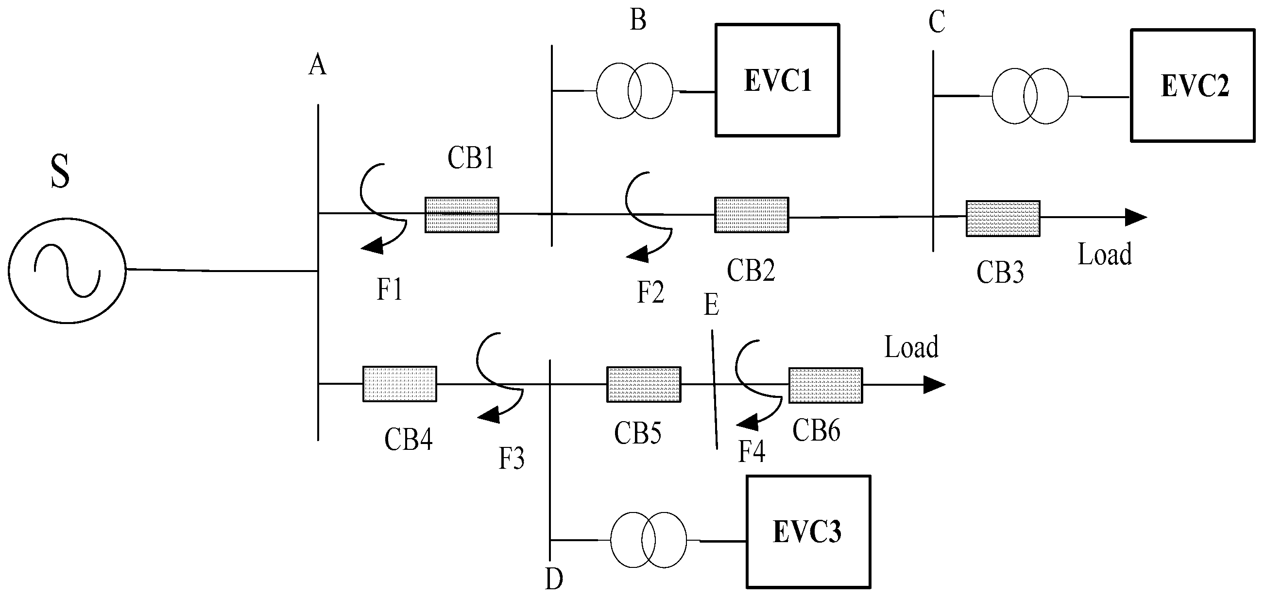
Figure 1. Schematic diagram of distribution network with charging and discharging stations. Where A, B, C, and D are the bus bars.
Energies 15 09065 g001
Figure 2. Double-ended power systems.
Energies 15 09065 g002
Figure 3. Circuit diagrams of positive sequence fault components. Where (a) is the positive sequence network with faults in line L of the double-terminal power supply linear system in Figure 2; (b) is the equivalent diagram of two additional power sources connected in series in the additional impedance branch; (c) is the pre-fault operation diagram of graph (b) decomposed by superposition theorem; (d) is the post-fault positive sequence fault component additional state diagram of graph (b) decomposed by the superposition theorem.
Energies 15 09065 g003aEnergies 15 09065 g003b
Figure 4. Positive sequence network diagram of fault components.
Energies 15 09065 g004
Figure 5. Positive sequence fault component network diagram for out-of-zone faults.
Energies 15 09065 g005
Figure 6. Schematic diagram of three-phase short-circuit fault protection.
Energies 15 09065 g006
Figure 7. Vertical protection logic diagram based on positive sequence comprehensive impedance.
Energies 15 09065 g007
Figure 8. Charging and discharging stations are connected to 10 kV distribution network model.
Energies 15 09065 g008
Figure 9. Overall load variation of distribution network under different permeability.
Energies 15 09065 g009
Figure 10. Comprehensive impedance and protection action of positive sequence component of Line1 ground fault. (a) Positive sequence integrated impedance. (b) Protection action condition.
Energies 15 09065 g010aEnergies 15 09065 g010b
Table 1. Additional impedance ΔZ under different fault types.
Fault TypeΔZ
Single phase earth faultZ2 + Z0
Two-phase ground faultZ2//Z0
Two-phase short-circuit faultZ2
Three-phase short-circuit fault0
Table 2. Overall load statistics of distribution network under different permeability.
Permeability of WaterMaximum Load/MWTime of Maximum Load/hMinimum Load/MWMinimum Load Time/hPeak Valley Difference/MWPeak Valley Differential/%
0%173.559:58104.963:0968.5939.52
25%175.4310:03105.173:1370.2640.05
50%177.309:51105.253:1172.0540.64
75%179.189:46105.323:1473.8641.22
100%180.559:35106.103:1574.4541.24
Table 3. Identification of line 10 protection at different positions and under different fault conditions.
Fault LocationFault TypeTransition Resistance/ΩPositive Sequence Integrated Impedance/ΩBraking Coefficient/kBrake Impedance/ΩTime/sSensitivityDecision Outcome
F1ABC4.950.050.3651.920.3111.23Out-of-area fault
F1BC0.020.020.3622.380.3131.26Out-of-area fault
F1CAG4.950.040.3655.620.3201.34Out-of-area fault
F2AB4.9547.570.360.250.2851.29In-area fault
F2ABG0.0223.180.360.120.2931.43In-area fault
F2CA0.0224.250.360.060.2891.37In-area fault
F3CA0.020.010.362.560.3161.31Out-of-area fault
F3CA1.050.030.364.410.3181.35Out-of-area fault
F4ABG9.950.020.3663.420.3161.32Out-of-area fault
F4CAG0.020.010.3641.640.3141.28Out-of-area fault
Note: BC represents the phases B and C short-circuit fault; ABC indicates a three-phase short-circuit fault; CAG indicates an interphase short-circuit grounding fault; ABG indicates an interphase short-circuit grounding fault; CA represents the phases C and A short-circuit fault.
Table 4. Identification of line 9 protection at different positions and under different fault conditions.
Fault LocationFault TypeTransition Resistance/ΩPositive Sequence Integrated Impedance/ΩBraking Coefficient/kBrake Impedance/ΩTime/sSensitivityDecision Outcome
F1ABC4.9550.150.3692.420.3151.37Out-of-area fault
F1BC0.0211.350.3646.220.3051.31Out-of-area fault
F1CAG4.9555.380.3698.620.3111.35Out-of-area fault
F2AB4.9552.850.3691.840.2981.29Out-of-area fault
F2CA0.0230.160.3674.580.3161.41Out-of-area fault
F4CAG9.9599.840.360.260.2911.26In-area fault
F4CAG0.0223.650.360.320.2951.28In-area fault
Note: ABC indicates a three-phase short-circuit fault; BC represents the phases B and C short-circuit fault; CAG indicates an interphase short-circuit grounding fault; AB represents the phases A and B short-circuit fault; CA represents the phases C and A short-circuit fault.
Publisher’s Note: MDPI stays neutral with regard to jurisdictional claims in published maps and institutional affiliations.