Abstract
This paper presents an experimental study on a single tank thermal energy storage (TES) system integrated with a cooking unit. The tank had a capacity of 45 L of oil. The cooking chamber was embedded in the storage tank, thereby eliminating the use of pumps and connecting pipes between the cooking unit and the storage unit. The system was designed to make good physical contact, circumferential and basally, with the cooking pot, to improve the rate of heat transfer. Experimental tests were performed with oil only and oil–rock pebbles as sensible heat storage materials. The charging unit was connected to the TES unit in such a way that it allowed circulation of oil between them during charging, using the thermosiphon principle. An electric heater rated at 800 W 240 V was inserted into the charging unit to charge the system. The thermal performance of the TES systems was evaluated in terms of the charging temperature, heat retention capacity, energy stored and cooking efficiency, and the overall heat lost coefficient. The results showed that the oil–rock system performed best, with a cooking efficiency of 64.9%, followed by the oil-only TES system, with 60.3%. Further tests on cooking indicated that the system was able to cook beans in 2.25 h and 2.0 h using the oil only and oil–rock pebbles thermal energy storage systems, respectively.
1. Introduction
Globally, fossil and wood fuels have continued to be the dominant source of energy for cooking and heating applications. This practice has resulted in a significant increase in greenhouse gases and the global climatic changes that are currently being experienced [1,2]. Most developing countries rely on wood fuels for domestic cooking and heating applications, due to poverty and inadequate access to a national electricity grid [1]. Nearly 75% of households in developing countries depend on firewood and charcoal fuel for cooking, by burning the fuels either in improved charcoal stoves or on three-stone locally designed stoves [3].
In Uganda, 88% of the total primary energy consumption for cooking comes from wood fuels [4]. In 2018, the Ministry of Water and Environment reported that Uganda’s forest cover had been reduced to 8%, down from 24% in the 1990’s [5]. Tabuti et al. [4] reported that the tree cutting for firewood and charcoal production for cooking in Bulamogi, a community in Northern Uganda, stood at 96%. This type of cooking is highly associated with environmental and health related problems, such as diseases due to inhalation of smoke from incomplete burning of firewood and climate changes [6]. Therefore, there is a need to develop cooking technologies that use clean alternative source of energy, such as wind, geothermal, and solar.
Among the renewable energy sources, solar energy has the potential to provide a solution to the current energy demand in most developing countries that are located within the sunbelt region. In Uganda, there is favorable solar irradiation, ranging from 1.8 MWh m−2 to 2.5 MWh m−2 per year, which is suitable for both electricity and heat production [7]. Utilization of solar energy for thermal applications such as cooking, heating, and drying is well recognized in the tropical and semi-tropical regions. Different versions of solar cookers have been developed and tested by a number of researchers [8,9,10,11,12,13,14], but most of these cookers require improvement, since their use is restricted to the sunny periods of the day. The intermittency and fluctuation in the intensity of the sun’s radiation limits the continuous usage of most solar energy appliances. In order to continuously use solar energy for thermal applications, without interruption by low/no sunshine periods, solar thermal energy storage (TES) is required [8,9,12].
Thermal energy can be stored as sensible heat, latent heat, and in thermochemical form. In sensible heat storage, energy is stored by raising the temperature of the storage material, without any change in phase. Latent heat storage involves heating a material until it experiences a phase change. Thermochemical heat storage uses reversible chemical reactions in which heat energy is absorbed by reactants (endothermic), and decomposition of the products into reactants releases the heat (exothermic). The heat energy stored can then be extracted from the storage material and used in cooking and other applications [15,16,17,18,19,20].
Sensible heat storage systems can be suitable for low income countries, because they are cheap, readily available, and simple and ease to fabricate and use. Examples of some of the commonly used sensible heat storage materials include water, oil, rock pebbles, and iron. The choice of the material for a TES system depends on a number of factors, such as cost, simplicity, robustness, temperature range for the application, and the ease of fabrication and use. Water is cheap and available but cannot be used for applications requiring temperatures above 100 °C, since expensive pressurizers would be required. The use of rocks requires a heat transfer fluid such as air or oil, to transport heat from the heating point to the storage medium [15,21,22]. Oil is a good TES material, since it can act both as a good heat transfer material and heat storage material at temperatures of up to about 230 °C, which is suitable for cooking.
Previous studies showed that heat can easily be stored in most TES materials for later use, but inadequate work has been reported on the heat extraction from the thermal storage. Okello et al. [23] experimentally investigated the heat extraction from a heated rock bed, by blowing air from the bottom to the top, where a cooking pot was placed. The results showed that the heating rate was directly proportional to the airflow rates, and there was significant loss of energy to the surrounding. Lentswe et al. [9] carried out a review of parabolic solar cookers with a thermal energy storage system. They highlighted gaps, such as the large-scale setup and the increased use of latent heat storage rather than sensible heat storage, while the type of food to be cooked using such systems is equally important. Nkhonjera et al. [11] grouped TES systems integrated with cooking units based on how heat is transported from the solar absorber to the cooking load. Most TES systems integrated with a cooking unit work on the principle of a heat exchanger, whereby heat is drawn from the storage material as it circulates at the base of cooking unit, or between the annular cavity between the storage tank and the cooking unit. Sharma et al. [14] developed and evaluated the performance of a latent heat storage unit for evening cooking in a solar cooker. The TES system consisted of two concentric cylinders: the outer cylinder acting as container for the storage material (PCM), and with the inner cylinder as a cooking pot. The PCM exchanged heat directly with the cooking load during the discharging cycle.
Mussard et al. [18] investigated a TES consisting of PCM capsules enclosed in a cylindrical container of HTF. The cooking pot sits on top of an aluminum plate that carries the capsules and closes the top of the storage unit container. The problem with this arrangement is that the areas occupied by the PCM capsules on the top aluminum plate can reduce area of contact with the cooking pot, leading to an increase in cooking time. Kumaresan et al. [24] carried out a performance assessment of a solar domestic cooking unit integrated with a TES system. The cooking unit was located away from the storage unit and the HTF could be delivered from the storage unit to the cooking unit using pipes and pumps. The geometry of the cooking unit was complex, in that it favoured cooking pots with round bases. In addition, the annular cavity between the two bowls can only accomodate a small quantity of the HTF at any point during cooking.
Kajumba et al. [20] investigated the performance of a cooking unit integrated with a TES system, in which the HTF was delivered to the cooking unit via a pipe. The cooking unit was located below the storage tank and the HTF flowed by gravity. The challenge with this system was that there were heat losses in the pipe between the cooking unit and the storage tank. Furthermore, the user had to collect the used HTF from the cooking unit and return it to the heat storage tank. Most of the TES systems that are connected by pipes require pumps to circulate the heat transfer fluid between the storage and the cooking unit. The disadvantage with this systems design includes an increase in system cost due to the pump, heat lost in the connecting pipes, and system failure in case the pump breaks down [11,20,25].
In this paper, we developed a TES system integrated with a cooking unit and tested its performance during charging and cooking. The cooking unit is embedded within the thermal storage unit, thereby eliminating the need for piping between the storage unit and the cooking unit. Charging through thermosiphon was adopted, to eliminate the use of pumps, which would have increased the system cost. The dimensions of the cooking stove were chosen based on the energy requirement suitable for a household of 4–5 persons, which is the average number of persons in a typical Ugandan household. Granite rock pebbles and Thermia Oil B were used as the heat storage materials in the oil–rock system; while Thermia Oil B was used as the heat storage material in the oil-only TES system. Thermia Oil B was used because it was available in the laboratory and its use was recommended by Tabu et al. [26] for heating applications at the temperatures up to about 230 °C suitable for cooking. The thermal performance of the TES system was investigated by calculating the total amount of energy stored during charging and the total amount of energy retained after 14 h in an inactive state. The cooking performance was investigated by computation of the efficiency of heat extraction from the TES system when the charging power was off. Further analysis was performed by cooking beans (a common sauce in Uganda that requires more energy to cook compared to other sauces such as groundnut, meat, fish, vegetables, etc.) during the charging cycle. This was done to investigate the effect of cooking on the temperature profiles within the thermal storage unit.
2. Materials and Methods
2.1. Experimental Method
2.1.1. Design and Construction of the TES System
The heat storage unit was designed to consist of two coaxial cylinders. The inner and outer cylinders had diameters of 40 cm and 50 cm and heights of 30 cm and 35 cm, respectively. The inner cylinder was made from a steel metal plate of thickness 1.5 mm, while the outer cylinder was made from a galvanized aluminum plate of thickness 0.27 mm. The space between the two cylinders was filled with glass wool, to insulate the inner cylinder, as shown in Figure 1A,B. The cooking unit was made by welding an aluminum pan of depth 11.5 cm and diameter of 20 cm on the top part of the inner cylinder, as shown in Figure 1A. A small rectangular hole of dimensions 10 cm by 6 cm was created on the top of the storage tank, and this allowed loading and emptying the storage and for fitting the k-type thermocouples (accuracy: ±2.2 °C) for temperature measurements. The cover of this hole was not tight; thereby acting as a safety valve, to release high pressure in the tank when the oil was hot. Table 1 provides a summary of the dimensions used in the construction of the various components of the system.
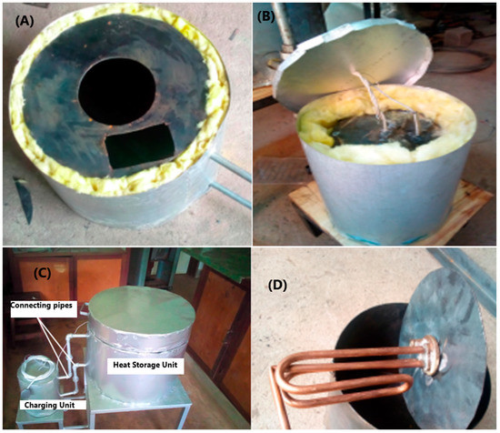
Figure 1.
Diagram showing the construction of the single tank thermal energy storage system: (A,B) the design of the top part and side insulation; (C) the complete storage unit with an external charging unit; and (D) the 800 W electric heater that was mounted inside the charging unit.

Table 1.
Summary of the dimensions of the thermal energy storage system.
The top cover of the storage unit was composed of a circular disc 5 cm thick and 60 cm in diameter. The space inside the disc was filled with glass wool for insulation. The circular disc was joined onto the storage unit using a hinge.
The charging unit was similarly made from two coaxial cylinders using steel plates of 1.5 mm thickness. The space between the cylinders was filled with glass wool for insulation. The diameter and height of the inner cylinder was 18 cm and 20 cm, respectively. Figure 1C shows the complete TES unit connected to the charging unit through valves, which were open during the charging cycle and closed during the heat retention test and during discharging. A heating element rated 800 W was fitted inside the boiler, as shown in Figure 1D and in the schematic in Figure 2. Thermocouples Tt and Tb were placed in the charging unit, to monitor the temperature of the liquid at the top and bottom, respectively.
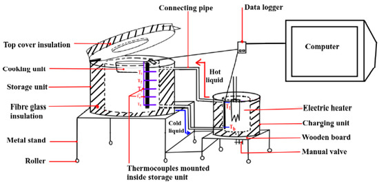
Figure 2.
The schematic diagram of a single tank storage system showing the storage unit, heating unit, connecting pipes, and measurement system.
The storage unit and the charging unit were connected by two pipes of internal diameter 1.6 cm, one running from the top part of the storage tank (inlet) and the other running from the bottom part of the storage tank (outlet).
2.1.2. Experimental Setup
Five K-type thermocouples supported by a hollow metallic pipe were mounted at equal distances of 5 cm apart along the bed, as shown in Figure 3A,B. Thermocouples were connected to a TC-08 data logger (Pico Technology, St. Neots, UK) that was interfaced with a dual core HP computer with a Linux operating system. The temperature profiles inside the storage unit and charging unit were recorded using a data logger that was configured to record the average value of 100 temperature readings after one minute. Figure 3C is the overall experimental setup of the storage unit and the charging unit. Experimental tests were performed by filling the heating chamber with 4.8 L of oil only, while the storage tank was filled, in turn, with oil only and oil–rock. In the oil only system, 45 L of oil was used in the experiment. An electric heater rated 800 W plugged into an AC supply of 240 V was then turned on. The temperature profiles inside the storage unit and charging unit were recorded using thermocouples at intervals of 1 min. The TES systems were designed to be charged to any temperature in the range 170 °C to 230 °C. This range was chosen as it is suitable for most domestic cooking applications and for safety reasons. Thermal Oil B was observed to start producing irritating smoke at temperatures above 230 °C. Each test was repeated 3 times, to ensure the reproducibility and reliability of results.
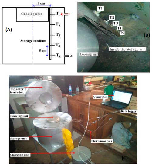
Figure 3.
Experimental setup for charging of the TES systems: (A) Schematic of the arrangement of thermocouples; (B) the actual arrangement of thermocouples fitted at known distances to the supporting stand; and (C) photograph of the complete experimental setup.
Figure 4 shows the scheme for filling the storage unit with granite rock pebbles. Granite rock pebbles, each of average mass 50 g and 3.62 cm in diameter, previously washed and dried, were added into the storage tank containing Thermal Oil B, as shown in the schematic in Figure 4c. The washing was done to remove dirt, which would otherwise have accumulated inside the pipes and impeded the flow of the HTF. The excess oil displaced above the inlet was run down using an exit tap located at the base of the charging unit.
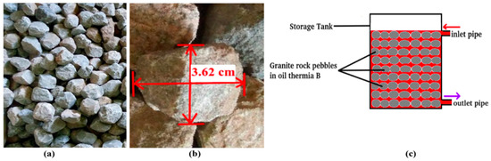
Figure 4.
(a) Granite rock pebbles washed and spread to dry, (b) dimension of a spherical pebble, and (c) schematic diagram of the storage tank containing granite rock pebbles and Thermal Oil B.
After the addition of the rock pebbles, 28 L of oil was collected as overflow from the storage tank. Hence the volume of granite rock pebbles added was 28 L and the volume of oil left in the storage was 17 L. The void fraction, ε, of the storage tank was calculated using Equation (1) to be 0.38. Based on this value of , the mass of rock pebbles added was estimated at 73 kg. The density of granite rock is 2640 kg m−3, according to Okello et al. [27].
where is the volume of the storage up to the inlet from the boiler, is the volume of granite rock pebbles added.
The thermophysical properties of the Thermal Oil B are given in Table 2. The temperature-dependent parameters for Thermia Oil B were obtained from Tabu et al. [26] Thermia Oil B was used because it can be heated to a temperature of 250 °C, far below its boiling point (355 °C) and well above the boiling point of water (100 °C), since most foods are cooked at the boiling point of water.
Table 2.
Thermophysical properties of Thermal Oil B (adapted from Tabu et al. [26]).
2.2. Thermal Performance Analysis of the TES System
The parameters used for evaluation of the thermal performance of the TES system were the real-time temperature profiles during charging, real-time temperature profiles during 14 h of the heat retention period, the total energy stored during charging, and the heat retention capacity.
2.2.1. Total Energy Stored
The total energy stored in a tank stratified into four segments during the charging cycle is given by:
where is the mean density of liquid in a segment, is the mean specific heat capacity of a segment, is the volume of liquid in the jth segments, and is the temperature difference in a given segment of the stratified tank.
The total energy stored, , in the oil–rock pebble storage tank stratified into four segments during charging is given by:
where and are the density and specific heat capacity of oil, is the void fraction, and are the density and specific heat capacity of granite rock pebbles, respectively, is the volume of the jth segment, and is the temperature difference between the two adjacent nodes of the jth segment of the stratified tank. Values of , , , and were obtained from [27,28].
2.2.2. Heat Energy Retained
After charging was stopped, the temperatures in the tank were recorded for 14 h. The energy retained in the storage unit was calculated using the general Equations (4) and (5) for the oil-only and oil–rock pebble systems, respectively:
where and are the mass and specific heat capacity of the storage fluid, respectively, is the average final temperature of the storage unit after the 14 h, and is the ambient temperature.
2.3. Analysis of Cooking Performance
2.3.1. Efficiency of Heat Extraction
To evaluate the efficiency of heat extraction of the TES systems, the TES was filled with oil only; and then later with both oil and rock pebbles. The TES was charged in turn up to a maximum average temperature of about 175 °C. Then 1 L of water at a temperature of 23.5 °C was added into the cooking vessel and heated up to boiling point . Using the method proposed by Karunanithy and Shafer [29], a temperature slightly below boiling point was chosen for evaluation of the efficiency of heat extraction. The rate of heat absorption from the storage unit during cooking was calculated using the general Equation (6):
where , , , and are mass of water, specific heat capacity of water, initial temperature of water, and heating time, respectively.
The rate of heat release from the storage unit was calculated using Equation (7) modified from Rismanchi et al. [30]:
where is the rate of heat loss from the storage unit, is the total surface area factor of the storage unit, and is the log mean temperature difference of the storage unit, defined by:
where , , and are the initial temperature of the storage unit, final temperature of the storage unit, and ambient temperature, respectively. In Equation (8), Ts,i must be greater than Tamb.
The overall heat transfer coefficient, U, was determined based on the method proposed by Velraj [31], as follows: the storage medium in the tank was raised to a higher operating temperature and left undisturbed. The temperature in the storage tank decreased slowly, and the average temperature inside the storage tank was recorded at a regular interval 1 min, and the variation of temperature with respect to time was observed. Recording of the temperature was continued, until the storage tank reached a lower temperature . The overall heat loss coefficient was then evaluated using Equation (9):
where , , , and are the mass of storage material inside the storage unit, specific heat capacity of the storage medium, total surface area of the storage unit, and time taken by the storage unit to cool, respectively. The efficiency of heat extraction from the storage unit was evaluated using Equation (10):
2.3.2. Rate of Energy Consumption during Cooking While Charging the TES System
The effectiveness of oil and oil–rock pebble TES systems in cooking kg of beans during charging was investigated. In the calculation of rate of heat energy consumed during cooking, it was assumed that the evaporation from the cooking unit at temperatures below boiling point was negligible. The rate of energy consumption during cooking was estimated using Equation (11), modified from [16] as:
where is the mass of beans cooked, is the specific heat capacity of beans, is the mass of water added in cooking unit, is the specific heat capacity of water, is the boiling point of water, is the initial temperature of water, and is the cooking time. The specific heat capacity of beans is 1563 J kg−1K−1, according to Dirisu et al. [32].
Equation (11) was used to determine the rate of energy consumption during morning cooking of rice, by using as the mass of rice added to the cooking vessel. The specific heat capacity of rice is 1501.4 J kg−1K−1, according to Marques et al. [33].
2.4. Uncertainty Treatment
Based on the standard k-type thermocouple accuracy, the uncertainty associated with temperature measurement was estimated to be ±2.2 °C. The accuracy of the Picolog TC-08 data logger used to record the data was given as ± 0.2% from the datasheet [34]. Using the standard error propagation relation for a function E, the uncertainty was evaluated according to as:
where , …, represent the uncertainty in the independent variables. For computation in this work, and . Therefore the uncertainty obtained from the calculated parameters was within 0.5% to 5.0%.
3. Results and Discussion
3.1. Temperature Profile of the Oil-Only TES System during Charging
The charging temperature profile for the oil-only TES system is shown in Figure 5. Observation of Figure 5A indicates that, when the heating element in the charging unit was switched on, the temperature Tt in the charging unit rose to 140 °C in 6 min of heating. Thereafter, it remained almost constant, as cold oil started to flow from the TES unit to the charging unit. The temperature T1 at the topmost part of the storage started to increase when the circulation started, with hot oil from the charging unit flowing into the topmost part of the TES unit, while cold oil from base was pushed into the charging unit by gravity. As thermal front propagated downwards, T2 started to increase, and later this was followed by T3, T4, and T5. After two and half hours of charging, there was a steady rise in temperature at almost all levels in the storage unit. This increase was due to the steady increase in temperature in the charging unit as circulation continued, and this is in agreement with the study by Kajumaba et al. [20] that used the thermisphon principle to charge a thermal storage. The temperature difference between the base and top of the storage unit at the end of charging period was 13.5 °C, showing a large reduction in thermal stratification. There was high stratification in the first hour, which later was eliminated as the circulation of oil between the charging unit and thermal storage unit continued. Figure 5B,C were additional tests repeated to show the reproducibility of the experimental results. The thermocouple Tb in the charging unit malfunctioned, and therefore its temperature was not considered in the analysis.
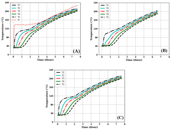
Figure 5.
Temperature profiles of an oil-only TES system, showing the similar profiles for the three charging tests.
3.2. Temperature Profile of the Oil–Rock Pebble TES System during Charging
Figure 6 shows the temperature profile of the oil–rock pebble TES system during charging. Observation of Figure 6A shows the similar behavior in the charging cycle as in Figure 5A, but it took longer to charge the oil–rock TES system than the oil-only system. As the hot oil circulates through the rock pebble store, it exchanges heat with the rocks. The temperature behavior through the pebbles depends on two critical factors, according to Schlipf et al. [35]: first, thermal convection, which makes the surface of the rock pebbles heat up very quickly; and second, the heat conduction to the inner core of the rock pebbles. As charging continued, heat was transferred to the bulk of the oil and rock pebbles at the base of the storage unit through the convection current, conduction, and thermal diffusion. After about 4 h of charging, there was a steady increase in temperature at all levels inside the storage unit. This increase can be attributed to the continuous rise in temperature in the charging unit. Similarly, Figure 6B,C were tests repeated to show the reproducibility of the experimental results.
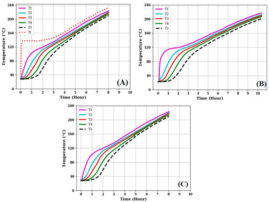
Figure 6.
Charging profiles for the oil–rock pebble system for the three experimental tests performed.
3.3. Energy Stored
During charging, the energy stored increased rapidly at the beginning in both TES systems, as shown in Figure 7. This rapid increase was due to the high convection that transported the heated oil from the charging unit to the storage unit. As charging progressed, the temperature gradient decreased, as temperature increased at the top of the storage unit. Inside the storage unit, the combined effects of thermal diffusion, conduction transfer, and convectional current caused the temperature to increase towards the bottom of the storage unit. This impeded the rate of energy build up in the storage unit, as depicted by the point of inflexion between 0.5 h and 1.5 h in both cases. Between about 1.2 h and 2.5 h, the combined effects of the storage thermal mass and temperature increase, caused a steady increase in the energy stored. Beyond 2.5 h, the rate of energy build up decreased, as the stratification was destroyed. Using Equations (2) and (3), the total energy stored at the end of the charging period in the oil-only TES was 13.7 MJ, while that in the oil–rock pebble TES system was 21.7 MJ. The oil–rock pebble TES system stored more energy compared to the oil only TES system because of the high thermal mass of the rocks. This result is in agreement with a study reported by Mawire et al. [19], which analyzed the energy and exergy performance of three sensible heat storage materials during charging; namely, sunflower oil, oil–small rock pebbles, and oil–big rock pebbles. They found that the most energy was stored in the oil–small rock pebbles, followed by the oil–big rock pebbles, and least in oil-only TES system. The is because rock pebbles have a high thermal storage capacity, due to their high thermal mass. The low thermal conductivity of rock means that it will not lose acquired heat energy easily.
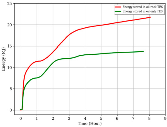
Figure 7.
Energy profiles of oil-only and oil–rock pebble TES systems during charging.
3.4. Heat Retention Capacity
The temperature profiles of the two TES systems during the 14 h cool down period are shown in Figure 8. Both TES systems were charged to average temperature of 210 °C, as indicated in Figure 8A,B, respectively. There was a general decrease in temperature at all levels in the storage tank for both systems during the heat retention test period. This can mainly be attributed to the heat lost to the surroundings due to insufficient insulation of the systems.
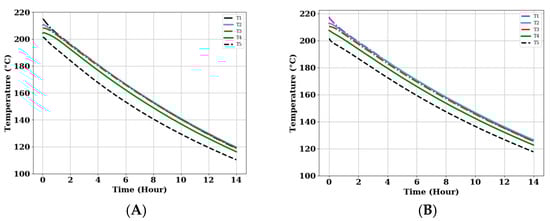
Figure 8.
Temperature profiles of the storage units over a 14 h period for the two TES systems: (A) Oil-only TES system, (B) Oil-Rock Pebble system.
After the 14 h of heat retention, the average temperatures of the storage tanks were 115 °C and 128 °C, for the oil-only and oil–rock pebbles TES systems, respectively. Based on these temperatures, the oil–rock pebble TES system retained more heat energy than the oil-only TES system. This is because the rock pebbles had a low thermal conductivity, which allowed the system to retain the heat longer.
Depending on the size of the storage, both systems could still be used to cook foodstuffs that are cooked by boiling, such as rice, Irish potatoes, and macrons (UNDP, 2021) [36].
3.5. Cooking Performance of the TES Systems
In order to understand how the developed TES system performed during cooking, several cooking experiments with different food stuffs were carried out. An uncontrolled cooking test (UCT) protocol based on Robinson and Ibraimo, was adopted [37]. The UCT is a field-testing protocol that assesses the task-based performance of cook stoves when cooking any meal and operated as per local conditions and practice. The parameters identified for evaluation of cooking performance were temperature profile in the cooking pot, efficiency of heat extraction, time response during cooking, and rate of energy consumption.
Figure 9 shows the temperature profiles of the two TES systems during the heating of 1 L of water that was initially at ambient temperature. Each TES system was first charged to a known maximum temperature, before being used to boil water. Figure 9a shows the temperature profile of water in the cooking pot and that of the bed in an oil-only TES system. The storage unit was charged to an average temperature of 175 °C. The temperature of water in the cooking unit increased from 24 °C to 96.2 °C in 32 min. At this point, the average temperature of the storage was 170 °C, representing a reduction in temperature of 5 °C.
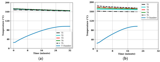
Figure 9.
Performance of the systems during boiling tests: (a) Oil-only TES system and (b) for Oil–rock pebble TES system.
A similar test was carried out with the oil–rock pebble system, and the observations are shown in Figure 9b. The storage tank was charged to an average temperature of 175 °C. The temperature of 1 L of water in the cooking unit increased from 24 °C to a temperature of 96.2 °C in 21 min. Additionally, there was high thermal gradient between the storage medium and water in the cooking unit, which enhanced the steady conduction of heat to the water in the cooking unit. The average temperature of the storage unit only dropped slightly during this period, to about 172 °C.
The cooking energy required by the TES system to boil 1 L of water from 24 °C to 96.2 °C was 303 kJ, which represents a cooking power of about 157.8 W and 240.5 W for the oil only and oil–rock pebble TES systems, respectively. These values correspond to an energy in kWh of 0.0842 for both the oil-only and oil–rock pebble TES systems. Therefore, the same amount of energy is required to boil 1 L of water using the two systems, but it took less time to reach a boil with the oil–rock pebble system compared to the oil-only system. Conventional cooking appliances take between 5 and 12 min to boil 1 L of water, and this represents a cooking power of about 0.45 kW [36].
A comparison between the performance of the oil-only and oil–rock pebble thermal energy storage systems in heating a liter of water is shown in Figure 10. The heating curve for the oil–rock pebble has a steeper gradient compared to the oil-only TES system. This is because of the high energy stored in the oil–rock system compared to the oil-only TES system. The higher the energy stored, the higher available power that can be extracted for cooking, and therefore the faster the rate of cooking.
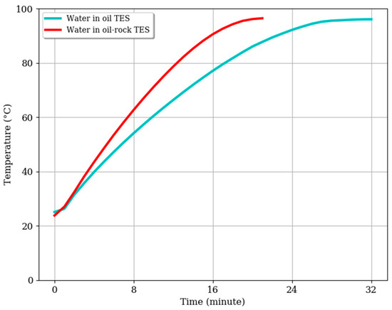
Figure 10.
Comparison of the performance of the oil-only and oil–rock pebble system when used to heat 1 L of water.
3.6. Efficiency of Heat Extraction of the TES Systems
Efficiency of heat extraction is one of the parameters used for evaluation of the cooking performance of a TES system. It is defined as the ratio of the rate of heat absorption from the storage tank to the optimum rate of heat released by the storage during the cooking period. To determine the efficiency of heat extraction of each TES system, the TES system was charged to a known maximum temperature. Then a known quantity of water was added to the cooking unit and left to boil entirely, using the energy stored in the storage tank. The efficiency of heat extraction for each TES system was evaluated using Equation (10). Table 3 shows the time taken (in minutes) to boil 1 L of water, rate of energy extraction from the storage Qabs (W), rate of energy loss during the test period Qloss (W), rate of energy release by the TES system in this period Qrel (W), and efficiency of heat extraction η (%). Generally, the oil–rock system performed better than oil-only system.
Table 3.
Efficiency of heat extraction and time response of the TES system during boiling of water.
The efficiency of heat extraction for the oil-only TES system was 60.3%, while that of an oil–rock system was 64.9%. These efficiency values show the fraction of heat energy actually used to boil the 1 L of water. The extended times of 32 min and 21 min obtained for the oil-only TES and oil–rock pebble TES systems, respectively, can be attributed to the heat energy wastage due to ineffective insulation. Moreover, there was a gap of air between the base of the cooking pan and the cooking chamber, which could have reduced the rate of heat conduction to the cooking contents.
3.7. Temperature Profiles of the TES Systems during Cooking While Charging
3.7.1. Cooking while Charging Completely Discharge Storage
Cooking tests were performed on the system while charging. This was used to simulate how such a system would perform during the day, while charging with solar energy and cooking at the same time.
Figure 11 shows the temperature profile of the oil-only TES system during cooking 500 g of beans as charging progressed. The oil-only TES system was charged to an average temperature of 166 °C, and then 500 g of beans and 1 L of water were added into the cooking unit. This caused a stagnation in the temperature profile of the storage unit, as indicated by the notches at about 4.7 h observed in Figure 11. It took about 20 min for the beans in the cooking unit to begin boiling.
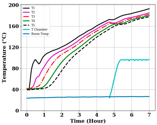
Figure 11.
Temperature profiles of the oil-only TES system during cooking 500 g of beans while charging.
However, charging continued, but fairly slow compared to the initial charging rate, after the mixture of beans and water in the cooking vessel reached boiling point. The saw-tooth patterns in the cooking unit temperature profile at cooking temperature in Figure 11 correspond to the times the cooking chamber was opened to check on the cooking content, as is a routine practice during normal cooking. After 2 h 20 min of cooking, the beans were tested and found to be fully cooked.
3.7.2. Cooking While Charging a Partially Charged Storage Unit
The initial storage unit temperature was about 150 °C. It was then charged to about 165 °C, and then beans and water were added to the cooking unit. The cooking profiles are only shown from the time 500 g of beans were added into the cooking unit up to the time the beans were fully cooked. Beans were cooked in 2 h. The valley in the cooking unit profile in Figure 12 shows the moment when the cooking unit was opened and cold water was added to the cooking contents, as is a routine cooking practice. Generally, cooking during charging had little effect on the charging of the TES systems.
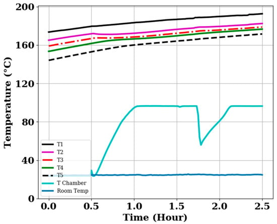
Figure 12.
Temperature profiles of the pre-heated oil–rock pebble TES system during cooking 500 g of beans while charging.
3.8. Overall Heat Transfer Coefficient
The overall heat transfer coefficient UsAs of the storage unit was determined over a heat retention time of 14 h, using Equation (9). The oil-only TES system was used in this experiment and was considered to represent a good approximation of the UsAs value for the oil–rock pebble TES system as well. The average temperature of the storage unit was 207 °C, and the final average temperature after 14 h was 116 °C. Using these temperature values, the log mean temperature difference (LMTD) was calculated using Equation (8). The overall heat transfer coefficient UsAs of the storage unit was calculated to be 0.96 W/K. This is a fairly high value and represents the ineffectiveness of the fiberglass insulation in retaining heat energy. The UA-values of any insulation material depend on the thermal conductivity of the insulation, and thermal conductivity is also temperature dependent, as discussed in Villasmil et al. [38]. As the temperature of the insulation material increases, thermal conductivity also increases.
3.9. Cooking after the Heat Retention Period
Table 4 shows the trend in time and efficiency of heat extraction during the cooking of 500 g of rice after a 14 h cool down period, using the oil-only and oil–rock pebbles as TES materials. The time taken to cook 500 g of rice was small in the oil–rock pebble TES system compared to in the oil-only TES system. This is because the oil–rock pebble TES system retained more heat energy. The oil–rock pebble TES system retained more heat energy after the 14 h of inactivity because of its high thermal storage mass. Therefore, at the end of the 14 h cool down period, there was a high thermal gradient between the storage materials and the cooking unit in the oil–rock pebble system. This enhanced the rapid conduction of heat energy to the cooking contents. This makes the oil–rock pebble TES system more efficient than its oil-only counterpart.
Table 4.
Efficiency of heat extraction during morning cooking using the oil-only and oil–rock pebble TES systems.
Although both systems were able to cook rice, they took a longer time compared to cooking rice with the convectional cooking methods [25].
4. Conclusions
A thermal energy storage system integrated with a cooking unit was developed, and its thermal and cooking performance was evaluated. The TES system was charged passively using the thermosiphon principal, which eliminated the use of pumps. The temperature profiles of the TES system rose more rapidly at the start of the charging period than towards the end. The heat retention tests of the TES systems also showed that the oil–rock pebble TES system retained more heat energy (16.21 MJ) than the oil-only TES system (9.24 MJ). This implies that the addition of rock pebbles to the oil thermal energy storage tank improved the heat retention capacity of the TES system.
The efficiency of heat extraction for the oil-only TES system was 60.3%, and that of the pebbled bed TES system was 64.9%. The temperature of water increased from 24 °C to 96.2 °C in 32 and 21 min for the oil-only and oil–rock units, respectively. Cooking tests carried out with the TES systems during charging showed that the oil-only TES system cooked beans in 2 h 20 min. The time duration to cook beans was reduced in the oil–rock TES system that was already at a high initial temperature. Thus, the TES system developed performed relatively well compared to the conventional means of cooking and can therefore be recommended for domestic applications. Moreover, the cooking tests carried out with the TES systems during charging revealed that cooking while charging does not greatly affect the charging. Therefore, cooking can be carried out during charging of the storage tank. However, the oil–rock pebble TES system was more efficient when used for cooking after charging the TES system. The cooking tests carried out after the 14 h retention period revealed that the oil–rock pebble TES system performed better than the oil-only TES system. This is because the oil–rock pebble TES systems retained more heat energy than its oil-only TES counterpart.
The use of a single TES tank system embedded within a cooking unit is highly recommended for application in an indirect solar cooker, since this minimizes the heat lost through the connecting pipes to an external cooking point. The system does not require a pump, making it cheaper compared to other designs that require a pump to circulate oil to an external cooking point. The design is simple and similar to conventional cooking methods, where cooking is done on top of the cook stove.
Author Contributions
D.O.: Conceived and designed the experiments; Analyzed and interpreted the data; Sourced funding; Compiled and edited the paper; R.O.: Conceived and designed the experiments; Performed the experiments; Analyzed and interpreted the data; Wrote the paper; K.N.: Analyzed and interpreted the data; Edited the paper; Funding acquisition and Project administration; J.C.: Conceived and designed the experiments; Performed the experiments; Analyzed and interpreted the data. All authors have read and agreed to the published version of the manuscript.
Funding
This research was funded by the SIDA (the Swedish International Development Agency) through ISP (International Science Programme, Upsala University); the Norwegian Agency for Development Cooperation (NORAD) through EnPe (Energy and Petroleum) capacity 5 project and ADB-HEST project (African Development Bank-Higher Education, Science and Technology).
Data Availability Statement
Not applicable.
Acknowledgments
The authors would like to thank the Physics department of Makerere University for providing the research environment.
Conflicts of Interest
The authors declare no conflict of interest.
Nomenclature
| As | surface area of storage unit, m2 |
| cav | average specific heat capacity, J kg−1K−1 |
| cp | specific heat capacity at constant pressure, J kg−1K−1 |
| cp,b | specific heat capacity of beans, J kg−1K−1 |
| cp,w | specific heat capacity of water, J kg−1K−1 |
| Eret | heat energy retained, J |
| Et | total heat energy stored, J |
| ETC | effective thermal conductivity |
| HTF | heat transfer fluid |
| LMTD | log mean temperature difference |
| m | mass, kg |
| mb | mass of beans, kg |
| Qabs | rate of heat absorption, W |
| Qloss | rate of heat loss, W |
| Qrel | rate of heat release, W |
| T | temperature, °C |
| ΔT | temperature difference in a segment, °C |
| Tamb | ambient temperature, °C |
| Tboil | boiling temperature, °C |
| TES | thermal energy storage |
| Tf | final temperature, °C |
| Ts,f | final temperature of storage, °C |
| Ts,i | initial temperature of storage, °C |
| Tw,i | initial temperature of water, °C |
| Tw,max | maximum temperature of water, °C |
| UCT | uncontrolled cooking test |
| Us | overall heat transfer coefficient of storage, W m−2K−1 |
| V | volume, L |
| Greek letter | |
| void fraction | |
| density, kg m−3 | |
| efficiency, | |
| Subscript | |
| av | average |
| j | segment |
| o | oil |
| r | rock |
| amb | ambient |
References
- Rehfuess, E.; World Health Organization. Fuel for Life: Household Energy and Health. World Health Organization, 2006. Available online: https://apps.who.int/iris/handle/10665/43421 (accessed on 8 August 2022).
- Joshi, S.B.; Jani, A.R. Design, development and testing of a small-scale hybrid solar cooker. Sol. Energy 2015, 122, 148–155. [Google Scholar] [CrossRef]
- Mehetre, S.A.; Panwar, N.L.; Sharma, D.; Kumar, H. Improved biomass cookstoves for sustainable development: A review. Renew. Sustain. Energy Rev. 2017, 73, 672–687. [Google Scholar] [CrossRef]
- Tabuti, J.R.S.; Dhillion, S.S.; Lye, K.A. Firewood use in Bulamogi County, Uganda: Species selection, harvesting and consumption patterns. Biomass Bioenergy 2003, 25, 581–596. [Google Scholar] [CrossRef]
- MWE. Water and Environment Sector Performance Report 2018. Available online: https://www.mwe.go.ug/library/sector-performance-report-2018 (accessed on 1 August 2022).
- De, D.K.; De, N.N.; Nathaniel, M.; Olawole, K. Minimizing energy usage in cooking to protect environments and health. Int. J. Energy Environ. Res. 2014, 2, 20–44. [Google Scholar]
- Mubiru, J.; Banda, E.J.K.B.; D’Ujanga, F.; Senyonga, T. Assessing the distribution of monthly mean hourly solar irradiation at an African Equatorial site. Energy Convers. Manag. 2007, 48, 380–383. [Google Scholar] [CrossRef]
- Muthusivagami, R.M.; Velraj, R.; Sethumadhavan, R. Solar cookers with and without thermal storage—A review. Renew. Sustain. Energy Rev. 2010, 14, 691–701. [Google Scholar] [CrossRef]
- Lentswe, K.; Mawire, A.; Owusu, P.; Shobo, A. A review of parabolic solar cookers with thermal energy storage. Heliyon 2021, 7, e08226. [Google Scholar]
- Nahar, N.M. Performance and testing of a hot box storage solar cooker. Energy Convers. Manag. 2003, 44, 1323–1331. [Google Scholar] [CrossRef]
- Nkhonjera, L.; Bello-Ochende, T.; John, G.; King’ondu, C.K. A review of thermal energy storage designs, heat storage materials and cooking performance of solar cookers with heat storage. Renew. Sustain. Energy Rev. 2017, 75, 157–167. [Google Scholar] [CrossRef]
- Lentswe, K.; Mawire, A.; Owusu, P. Experimental Energetic and Exergetic Performance of a Combined Solar Cooking and Thermal Energy Storage System. Energies 2022, 15, 8334. [Google Scholar] [CrossRef]
- Soria-Verdugo, A. Experimental analysis and simulation of the performance of a box-type solar cooker. Energy Sustain. Dev. 2015, 29, 65–71. [Google Scholar] [CrossRef]
- Sharma, S.D.; Buddhi, D.; Sawhney, R.L.; Sharma, A. Design, development and performance evaluation of a latent heat storage unit for evening cooking in a solar cooker. Energy Convers. Manag. 2000, 41, 1497–1508. [Google Scholar] [CrossRef]
- Okello, D.; Nydal, O.J.; Banda, E.J.K. Experimental investigation of thermal de-stratification in rock bed TES systems for high temperature applications. Energy Convers. Manag. 2014, 86, 125–131. [Google Scholar] [CrossRef]
- Buddhi, D.; Sharma, S.D.; Sharma, A. Thermal performance evaluation of a latent heat storage unit for late evening cooking in a solar cooker having three reflectors. Energy Convers. Manag. 2003, 44, 809–817. [Google Scholar] [CrossRef]
- Schwarzer, K.; da Silva, M.E.V. Solar cooking system with or without heat storage for families and institutions. Sol. Energy 2003, 75, 35–41. [Google Scholar] [CrossRef]
- Mussard, M.; Nydal, O.J. Charging of a heat storage coupled with a low-cost small-scale solar parabolic trough for cooking purposes. Sol. Energy 2013, 95, 144–154. [Google Scholar] [CrossRef]
- Mawire, A.; Lentswe, K.A.; Okello, D.; Nyeinga, K.; Lugolole, R. Energy and exergy performance of three sensible heat storage systems during charging. In Proceedings of the 2018 6th International Renewable and Sustainable Energy Conference (IRSEC), Rabat, Morocco, 5–8 December 2018; IEEE: Piscataway, NJ, USA, 2018; pp. 1–6. [Google Scholar]
- Kajumba, P.K.; Okello, D.; Nyeinga, K.; Nydal, O.J. Experimental investigation of a cooking unit integrated with thermal energy storage system. J. Energy Storage 2020, 32, 101949. [Google Scholar] [CrossRef]
- Gautam, A.; Saini, R.P. A review on sensible heat based packed bed solar thermal energy storage system for low temperature applications. Sol. Energy 2020, 207, 937–956. [Google Scholar] [CrossRef]
- Prieto, C.; Cooper, P.; Fernández, A.I.; Cabeza, L.F. Review of technology: Thermochemical energy storage for concentrated solar power plants. Renew. Sustain. Energy Rev. 2016, 60, 909–929. [Google Scholar] [CrossRef]
- Okello, D.; Nydal, O.J.; Nyeinga, K.; Banda, E.J. Experimental investigation on heat extraction from a rock bed heat storage system for high temperature applications. J. Energy South. Afr. 2016, 27, 30–37. [Google Scholar] [CrossRef]
- Kumaresan, G.; Vigneswaran, V.S.; Esakkimuthu, S.; Velraj, R. Performance assessment of a solar domestic cooking unit integrated with thermal energy storage system. J. Energy Storage 2016, 6, 70–79. [Google Scholar] [CrossRef]
- Kajumba, P.K.; Okello, D.; Nyeinga, K.; Nydal, O.J. Assessment of the energy needs for cooking local food in Uganda: A strategy for sizing thermal energy storage with cooker system. Energy Sustain. Dev. 2022, 67, 67–80. [Google Scholar] [CrossRef]
- Tabu, B.; Nyeinga, K.; Chaciga, J.; Okello, D. Thermal Performance of Selected Oils in Uganda for Indirect Solar Domestic Cooking Applications. Tanzan. J. Sci. 2018, 44, 77–90. [Google Scholar]
- Okello, D.; Foong, C.W.; Nydal, O.J.; Banda, E.J. An experimental investigation on the combined use of phase change material and rock particles for high temperature (350 °C) heat storage. Energy Convers. Manag. 2014, 79, 1–8. [Google Scholar] [CrossRef]
- Mawire, A.; Taole, S.H. Experimental energy and exergy performance of a solar receiver for a domestic parabolic dish concentrator for teaching purposes. Energy Sustain. Dev. 2014, 19, 162–169. [Google Scholar] [CrossRef]
- Karunanithy, C.; Shafer, K. Heat transfer characteristics and cooking efficiency of different sauce pans on various cooktops. Appl. Therm. Eng. 2016, 93, 1202–1215. [Google Scholar] [CrossRef]
- Rismanchi, B.; Saidur, R.; Boroumandjazi, G.; Ahmed, S. Energy, exergy and environmental analysis of cold thermal energy storage (CTES) systems. Renew. Sustain. Energy Rev. 2012, 16, 5741–5746. [Google Scholar] [CrossRef]
- Velraj, R. Sensible heat storage for solar heating and cooling systems. In Advances in Solar Heating and Cooling; Elsevier Ltd.: Amsterdam, The Netherlands, 2016. [Google Scholar] [CrossRef]
- Dirisu, J.O.; Oyedepo, S.O.; Fayomi, O.S.I. Thermal energy assessment of oil bean stalk as a novel additive to building ceilings. In AIP Conference Proceedings; AIP Publishing LLC: Melville, NY, USA, 2019; Volume 2190. [Google Scholar]
- Marques, B.; Tadeu, A.; Almeida, J.; António, J.; de Brito, J. Characterisation of sustainable building walls made from rice straw bales. J. Build. Eng. 2020, 28, 101041. [Google Scholar] [CrossRef]
- Pico TC-08. Available online: https://www.picotech.com/download/datasheets/usb-tc-08-thermocouple-data-logger-data-sheet.pdf (accessed on 7 October 2022).
- Schlipf, D.; Schicktanz, P.; Maier, H.; Schneider, G. Using sand and other small grained materials as heat storage medium in a packed bed HTTESS. Energy Procedia 2015, 69, 1029–1038. [Google Scholar] [CrossRef]
- UNDP. Cooking with Electricity in Uganda: Barriers and Opportunities. 2020. Available online: https://mecs.org.uk (accessed on 6 September 2022).
- Robinson, J.; Ibraimo, M.; Pemberton-Pigott, C. The Uncontrolled Cooking Test: Measuring Three-Stone Fire Performance in Northern Mozambique. Available online: http://cleancookstoves.org/binary-data/DOCUMENT/file/000/000/82-1.pdf (accessed on 26 October 2022).
- Villasmil, W.; Fischer, L.J.; Worlitschek, J. A review and evaluation of thermal insulation materials and methods for thermal energy storage systems. Renew. Sustain. Energy Rev. 2019, 103, 71–84. [Google Scholar] [CrossRef]


Publisher’s Note: MDPI stays neutral with regard to jurisdictional claims in published maps and institutional affiliations. |
© 2022 by the authors. Licensee MDPI, Basel, Switzerland. This article is an open access article distributed under the terms and conditions of the Creative Commons Attribution (CC BY) license (https://creativecommons.org/licenses/by/4.0/).