Article

Flow around an Oscillating Cylinder at Low Reynolds Number with Forced Convection: Effect of Corner Radius and Reynolds Number

Department of Mechanical Engineering, Khalifa University of Science and Technology, Abu Dhabi P.O. Box 127788, United Arab Emirates
*
Author to whom correspondence should be addressed.
Energies 2022, 15(23), 9145; https://doi.org/10.3390/en15239145
Submission received: 21 October 2022 / Revised: 15 November 2022 / Accepted: 30 November 2022 / Published: 2 December 2022
(This article belongs to the Special Issue Modelling and Computations of Fluid Mechanics for Energy System)

Abstract

:
This numerical study investigated the flow-induced vibration (FIV) on non-heated and heated cylinders with different normalized corner radii (r*) at different Reynolds numbers (Re). Four different values of r* were considered (i.e., 0 (square cylinder), 0.5, 0.75, and 1.0 (circular cylinder)) at three different Re: 100, 150, and 200 within the laminar regime. The cylinder constrained in the axial direction and oscillated transversally was considered for a fixed nondimensional cylinder mass ( m * )   of 10 and a reduced velocity (Ur) of 4.92. The effect of r* and Re could be seen in the vibration modes of cylinders. The two-dimensional incompressible Navier–Stokes and energy equations were solved together with Newton’s Second Law governing the motion of the cylinder with the help of a computational solver. Four different modes were observed in this study: Mode-I characterized by exceptionally low amplitude; Mode-II characterized by fluctuating amplitude known as hysteresis (beating); Mode-III characterized by high amplitude due to synchronization or lock-in; and Mode-IV characterized by the monotonic oscillation of fixed amplitude. For r* = 1, synchronization phenomenon/lock-in was observed. For the heated cylinder cases, due to the change in the normalized corner radius, a notable change in nondimensional vibrational amplitude A / D and the average Nusselt number N u a v g was seen. It was observed that A/D was higher when lock-in occurred (at Re = 100 and r* = 1), leading to a rise in N u a v g by 47.9% compared to Re = 100 and r* = 0. Due to the change in r*, a shifting phenomenon was observed at Re = 150, r* = 0.75 and Re = 200, r* = 1. A major change in N u a v g was observed from the circular cylinder to square cylinder at different Re. The beating phenomenon was observed at Re = 100 for r* = 0.75, which was similar to that occurring at Re = 150 and r* = 0.5, and those at Re = 200 and r* = 0. Heat transfer and wake structure parameters were found to be dependent on r* and Re.

1. Introduction

Structures installed onshore and offshore are confronted by vibrations and fluid flows such as heat exchanger tubes, tubes in power plants, nuclear fuel rods, offshore risers, submarine oil pipelines, and electric transmission lines. A phenomenon known as flow-induced vibration (FIV) is majorly observed, which reduces thee operational time and effectiveness of installations. Numerical studies over a fixed cylinder have previously been conducted at a fixed Reynolds number (Re) [1,2,3,4].
Flow-induced vibration (FIV) on a single-cylinder has been researched in the past decade. Detailed reviews can be found in Feng [1], Jauvtis and Williamson [2], and Sarpkaya [3]. Williamson and Govardhan [4] summarized the fundamental results generated in past decades. Results obtained from the experimental and computational studies were compared and analyzed. Various phenomena such as lock-in and wake galloping were observed for certain values of U r . Khalak and Williamson [5] illustrated the effect of mass-damping on vortex shedding and amplitude modes. Two types of response have been observed for varying m * ξ . At low m * ξ , the response can be divided into three different branches: initial, upper, and lower. For high m * ξ , the response can be divided into two different branches: upper and lower [1]. Williamson and Roshko [6] were able to dictate the nature of the response and vortex shedding related to them. At the lower phase angle and initial branch, the “2S” type of vortex shedding (Von Karman Street) was observed while at the high phase angle, and a lower branch was associated with the “2P” type of vortex shedding. Brika and Laneville [7] exhibited the transverse response of a long flexible cylinder with a low damping ratio. On the basis of velocity increment, the response of the cylinder can be divided into two branches: lower and upper. When velocity was increased at a constant rate, the “2S” type of vortex shedding was observed. When velocity was changed at a rapid rate, “2P” type of vortex shedding was observed. Shiels et al. [8] numerically studied the transverse oscillation of a circular cylinder at Re = 100 using the viscous-vortex method. The results asserted that the body undergoes higher vibrational amplitude when the vortex shedding frequency approaches the natural frequency of the cylinder. The concept of “effective” dynamic parameter was introduced for zero damping, which included the effect of mass and elasticity. Another important phenomenon was galloping, which was also another format of vortex-induced vibration. Robertson et al. [9] investigated the rotational and translational galloping of rectangular sections with varying aspect ratio at constant Re = 250. Due to galloping, vibrational amplitude of the square cylinder continuously increased with an increment of U r . The frequency of galloping was lower than the vortex shedding frequency while both frequencies were at lock-in overlaps. This is the typical difference between lock-in and galloping. Alam [10] numerically studied the effect of mass and damping on the characteristics of a vibrating cylinder at Re = 150 for aa tandem cylinder. Vibrational amplitude was dictated by the spacing from the upstream cylinder.
The effects of corner radius on FIV have been investigated both numerically [11] and experimentally [12,13]. Miran and Sohn [14] studied the effect of the rounded corner on the static cylinder at Re = 500 with a large eddy simulation for six different values of r* = 0.1–0.5. The results stated the effect of the orner radius on the flow pattern around the cylinder. Adeeb et al. [15] used finite volume and immersed-boundary lattice Boltzmann methods to study the flow around tandem cylinders of various configurations. Flow characteristics were affected due to spacing ratio L / D and r* as the wake of the upstream cylinder interacts with the downstream cylinder. The study was analyzed for six different r* = 0.1–0.5 and spacing ratios in the range of 1.5 < L / D < 10 at constant Re = 100. The key conclusion was on the regimes discovered for different spacing ratios. Basically, two regimes were observed: single-body regime with 1.5 < L / D < 3 and two-body regimes with 3 < L / D < 10 . Zhao and Zhao [16] numerically investigated the effect of the corner radius for constant Re = 200 but different U r . The effect of the corner radius (r* = 0–0.5) on galloping and lock-in was observed (i.e., galloping was completely suppressed after r* = 0.1.   A / D ) as lock-in increased due to a change in r* from 0 and 0.5. In further analysis, the beating was divided into two parts: type A and type B. Sen and Mittal [17] demonstrated FIV on a square cylinder with varying 60 < Re < 250. The cylinder vibrated both in the axial and transverse directions, mainly with three different regimes (i.e., primary lock-in, desynchronization, and secondary lock-in). Ghozlani et al. [18] numerically studied the effect of orientation on FIV on a square cylinder. Different angle of attacks have been studied to achieve the optimum configuration. Wu et al. [19] conducted a large eddy simulation to study the flow around square cylinders of different aspect ratios. Vijay et al. [20] numerically investigated FIV on an elliptical pipe of different aspect ratios ( A R : major axis to minor axis) of 0.1, 0.25, 0.5, 0.75, and 1.0 at Re = 100. For A R = 0.1 , a maximum normalized amplitude ( A / D ) of 1.178 was observed. At A R = 1.0 0, the A / D decreased to 0.599. It was shown that at an even higher mass ratio with a lower A R , a normalized amplitude of 1.097 was reached. This suggests that vibrational response is dictated by the mass ratio and A R was identified as the main control parameter. Zhao et al. [21] numerically investigated the FIV on an elliptical pipe at different A R = 0.67 = 1.5 with Re = 805–850. It was observed that at the lower reduced velocity, the smaller vibrational amplitude was encountered for a cylinder with lower A R compared to that of A R = 1 . Ding et al. [22] investigated the 2D-URANUS simulation for energy harvesting at 30,000 < Re 105,000. The effect of surface roughness was applied to control the turbulence. Surface roughness for filleted radius creates a scope of work for further investigation.
Study of non-isothermal flow around a cylinder provides a better understanding of the coupled FIV and heat transfer [23]. This is important for a number of engineering applications [24]. The tube heat exchanger in power plants is subjected to elevated temperature, which induces thermal stress, and at the same time, FIV causes structural fatigue. In heat exchangers, it was noticed that high FIV occurs within the heat exchanger pipes [23,24]. There is wide scope to eliminate these failures by investigating basic geometries and creating modifications [25,26,27] to eliminate FIV and improve thermal management. Heat transfer can be understood with natural, mixed, and forced convection. Currently, for this research, forced convection was taken into consideration, hence the thermal buoyancy effect was out of its scope. Izadpanah et al. [27] numerically examined the FIV on an oscillating cylinder with convective heat transfer at Re = 150 with varying U r = 3 8 and ξ = 0 0.1 demonstrating the change of N u a v g . At U r = 4 and ξ = 0.05 , the beating (modulation of amplitude) phenomenon was observed. The maximum heat transfer enhancement occurred at U r = 4 and ξ = 0 . Alam et al. [28] numerically investigated the heat transfer of a cylinder subjected to geometrical modification at Re = 150 and Pr = 0.7. The Nusselt number ( N u ) and friction coefficient ( C f ) were found to be directly correlated, which suggests that the heat transfer rate increases when more fluid remains attached to the surface. Kumar et al. [29] numerically investigated the heat transfer over the semi-circular cylinder with different Re = 50–2000 and Pr = 0.7, 10, and 100. It was observed that the heat transfer rate was higher while the drag was lower in the case of a circular cylinder compared to the semi-circular cylinder. The vortex shedding was observed between Re = 69–90 and drag was reduced until reaching Re = 140. Mahír and Altaç [30] numerically studied the effect of convective heat transfer on a tandem oscillating cylinder at Re = 100 and 200 with varying L / D = 2 10 N u a v g of upstream cylinder for L / D > 4 was similar to the isolated cylinder.
The above studies have shown the different FIV control configurations and the effect of corner radius on flow over the static cylinder. Most studies have focused on a single Re value for flow around a static cylinder. Very few studies have considered different Re for flow over a heated oscillating cylinder with different corner radii r*. The relevant flow and heat transfer behavior cannot be inferred or extrapolated from these limited results. Still, an enormous range of flow and heat transfer parameters for the cylinder with different corner radii have not been explored in the past. The objective of this numerical study is to understand the flow topology and heat transfer of an isothermal and heated oscillating cylinder for different r* = 0–1 and Re = 100, 150, and 200. This kind of oscillating heated cylinder has wide application in industrial heat exchangers.

2. Theoretical Modeling

2.1. Domain Discretization

Figure 1 shows a square cylinder having a mass per unit depth m , side length 2 R = D , and height 2 R = D vertically centered in a large computational domain of width L = 70 D and height H = 40 D , constituting a blockage ratio of 2.5%. The four edges of the square cylinder were filleted with a radius of r = 0 to R, corresponding respectively to a square and circular cylinder. The square cylinder movement was constrained in the x-direction. However, in the y-direction, it was allowed to move, driven, and dictated by the hydrodynamic forces and a spring-damper system with the given spring constant ( k ) and damping coefficient (c). In the isothermal case, the square cylinder surface was maintained at the same temperature (300 K) as for the ambient, otherwise, for the heated cylinder, the cylinder surface was set at a higher temperature (i.e., T S > T ) . The fluid entered the flow domain at the inlet with a velocity U and temperature T As the fluid flows around the square cylinder, hydrodynamic forces were generated, causing y -direction oscillating while enduring drag in the x -direction. The square cylinder motion was captured by remeshing the domain at each time step by solving the Laplace equation, which was subjected to an outer fixed ring that iteratively inflated nearly 10 times the value of the maximum attained displacement. For the non-isothermal cases, the heat was also transferred from the square cylinder to the fluid, and hence the fluid left the domain at a higher temperature. The flow of the fluid and the motion of the square cylinder were fully coupled.

2.2. Governing Equations and Boundary Conditions

The incompressible flow and heat transfer around a square cylinder is governed by the conservation of mass, momentum, and energy, respectively, expressed mathematically as:
· u = 0
( ρ u ) t + · ( ρ u u ) = p + · [ μ ( u + u T ) ]
( ρ c p T ) t + ( ρ c p u T ) = ( λ T )
where u , p , and T are the velocity, pressure, and temperature, respectively. The fluid properties are the density ( ρ ), viscosity ( μ ), specific heat capacity ( c p ), and thermal conductivity ( λ ). These governing equations are subjected to the initial conditions of u = 0 , v = 0 , and T = T . The associated boundary conditions are the Dirichlet at the inlet ( u = U , v = 0 , T = T ) and Neumann at the outlet ( u x = T x = 0 ) , no-slip and no penetration for the upper and lower boundaries ( u = U , v = 0 , T = T ) and the zero output pressure gradient ( p = p o u t )
For the heated cases, fluid properties such as viscosity μ , specific heat capacity, c p and thermal conductivity λ are assumed to be constant within the temperature range (300–350 K) without a loss of generality. The movement of the cylinder is governed by Newton’s Second Law of motion and is expressed as:
m d 2 Y d t 2 + c d Y d t + k Y = F y
where Y is the y -direction displacement of the square cylinder under the influence of the y -direction hydrodynamic force per unit length ( F y ). The initial conditions imposed on the square cylinder are Y = 0 and d Y d t = 0 .
The governing equations can be non-dimensionalized by introducing dimensionless parameters: t * = t U / ( 2 R ) , Y * = Y / ( 2 R ) , u * = u / U , p * = p / ρ U 2 , and T * = ( T T ) / ( T s T ) . The dimensionless governing equations are:
  * · u * = 0
u * t * + * · ( u * u * ) = * p * + 1 R e * · ( * u * + * u * T )
T * t * + * · ( u * T * ) = 1 R e P r * · ( * T * )
d 2 Y * d 2 t * + 4 π F n ξ d Y * d t * + ( 2 π F n ) 2 Y * = 2 C L π m *
N u a v g = 1 t t o t a l 0 t t o t a l N u   d t
where the dimensionless parameters are the reduced velocity U r = U f n D ; Reynolds number Re = 2 ρ U R μ ; Prandtl number Pr = c p μ k ; damping ratio ξ = c m f n ; mass ratio m * = 4 m π ρ ( 2 R ) 2 , normalized natural frequency F n = 2 R f n U ; undamped natural frequency f n = 1 2 π k m , lift coefficient C L = F y 1 2 ρ U 2 ( 2 R ) ; drag coefficient C D = F x 1 2 ρ U 2 ( 2 R ) ;   S t = f D U and N u = H .2 R k .

2.3. Solution Procedure and Validation

The governing equations for the discretized flow domain subjected to appropriate flow conditions were solved using Ansys Fluent, which is a finite volume-based solver solving Equations (5)–(7). The transient, convective, and diffusive terms are discretized respectively as first-order implicit, second-order central schemes. The second-order spatial scheme for the second derivatives and the central first derivatives including the time used to discretize the governing equations. Equation (8), governing the oscillatory motion of the square cylinder integrated using fourth-order Runge–Kutta method, was implemented via a user-defined function (UDF) within Ansys/Fluent environment. The unsteady solution was sought for the fluid subjected to incoming velocity and temperature, and the initial cylinder was positioned within the dynamic mesh region. The hydrodynamic forces were computed at each time step. The net y-direction hydrodynamic force was evaluated to determine the cylinder displacement and velocity at that instant time step [17,31]. The cylinder displacement was used to adjust the cylinder to the new position while the velocity accounted for the no-slip cylinder surface velocity in the successive time step solution of the fluid equations (Equations (5)–(7)). The time advancement was continued by the above process until a quasi-steady/periodic response was achieved. Solvers such as LBM [15] have also been employed by the researchers, but current adopted numerical provides more flexible approach. Standard flow initialization was executed from inlet with u * = 1 ,     v * = 0 , and T * = 1 . Computational methodology was set by convergence, CFL number, and solution accuracy, which is dependent on the time step, total flow time, and mesh. Sharma and Eswaran [32] studied a static square cylinder and concluded that convergence had no effect for less than Δ t * = 0.001 . Researchers have used Δ t * = 0.01 to obtain the correct results at fine grid, which was also used in this research study.

2.4. Grid Independence and Validation

Four different quadratic type meshes comprising 15,000 to 100,000 cells were used. For grid independence, flow around a circular cylinder was considered. The governing parameters were set to Re = 100, Pr = 0.7, f n = 0.2 , ξ = 0 , m * = 10 , and r* = 1 for each mesh. The corresponding reduced velocity used was U r = 4.92 . The overall domain size was fixed for all grid forms with a blockage ratio of 2.5%. Key parameters including A / D , C D m a x , and C L , m a x were computed and shown to be consistent as well as in agreement with the work in Table 1. Based on data provided in the table, it can be seen that Grid-I showed slight discrepancies, but the successive II through IV were almost identical. The change in the solutions from Grid-I and Grid-II was 2.73% for C D m a x , although this could vary for other parameters and the differences tended to be less than 2%. Compared to the work by Singh and Mittal [33] and the solution of Grid-II, the difference in the above important parameters was between an acceptable margin of 2–4%. Hence, Grid-II was used as the baseline mesh for the remaining numerical simulations as a compromise between acceptable accuracy and affordable computation time.

3. Result and Discussion

Figure 2 shows the frequency response with varying Reynolds numbers. As Re was increased between 100 and 200, lock-in occurred where the vortex shedding frequency ( f s ) matched the natural frequency of the cylinder ( f n = 0.203 ). At Re = 100, the maximum vibrational amplitude was observed, asserting the synchronization of f n   =   f s . These results reveal that at Re = 100, the response was characterized by higher vibrational amplitude, suggesting that lock-in was taking place. Figure 3 demonstrates the effect of Re on Y * and Z-vorticity ( ω z = v x u y ) at the three different values of Re. The onset of amplitude slight dipping was noticeable between Re = 150 and 200. Additional computations were made for Re > 200 and it was found that the oscillation amplitude started to decrease more rapidly [30]. They also stated that at a lower Re value (75–85), the flow was characterized by a beating behavior. The time histories of Y * and color contours of Z-vorticity are shown in Figure 3 depicting the different behaviors at each Re. At Re = 100, C(2S) vortex shedding can be observed while at Re = 150, the transition phase from 2S to C(2S) occurred. 2S refers to two single vortices when the cylinder moves downward and sheds vortices in a clockwise manner and vice-versa. C(2S) was similar to 2S, but the vortices coalesced downstream of the cylinder, and a parallel vortex street was formed past the cylinder. For Re = 200, vortex shedding was 2S, which later dispersed as C(2S).

3.1. Effect of Fillet on Vortex-Induced Vibration

Figure 4a depicts the results of A / D vs. Re of different corner radii r* = 0, 0.5., 0.75, and 1. Due to lock-in occurring for r* = 1, a higher A / D could be observed [4]. Different natures of vibrational amplitude were observed for the different configurations. The circular cylinder under Re = 100 was characterized with lock-in or synchronization, which exhibited the highest amplitude response compared to cases of other corner radii, which denotes this mode as mode-III. At Re = 100, vortex shedding frequency approaches the natural frequency of the cylinder, leading to lock-in or resonance phenomenon. The mode-III, vibrational mode propels and energizes all of the flow parameters including vibrational amplitude ( A / D ), average drag coefficient ( C D ¯ ), and maximum lift coefficient ( C L ). Figure 4b illustrates the C L vs. Re A / D and C L were closely correlated, which led to having an identical nature. Figure 4b,c presents C D ¯ and S t vs. Re with varying r* = 0–1.   C D ¯ was a function of vibrational amplitude and cylinder geometry. S t illustrates the vortex shedding frequency and evolution with respect to Re and r*.
Figure 5a,b shows the time histories of the C L and Z-vorticity contours for varying r* from 0 to 1 at Re = 100. For r* = 0.75, the hysteresis/beating phenomenon was more apparent, which can be denoted as mode-II (beating). Beating usually happens when two periodic variations exist and are close in frequency, which results in amplitude modulation following their lower frequency differences. This is more clearly depicted in the behavior of C L in Figure 5a for r* = 0.75. Singh and Mittal [33] have shown this hysteresis/beating behavior taking place at Re = 75–85 for cylindrical geometry with r* = 1. Due to change in the corner radii from 1 to 0.75, a shift in the nature of vibration occurred [16].
There was a significant drop for r* = 0.75 in A / D , C D ¯ , and C L compared to the r* = 1 in Figure 4a. Re = 100 and r* = 0.75 attested to the presence of mode-II vibration and the 2S vortex shedding type. which was unlike the C(2S) behavior that characterized the flow over the circular cylinder depicted in Figure 5a. Although the C D ¯ of the circular cylinder was higher than the filleted radius r* = 0.75 cylinder, its immediate wake region was less pronounced. Vortex shedding for r* = 1 merged downstream in the wake of the cylinder, the vortex shedding for r* = 0.75 was incepted at the sides of the cylinder, and was stronger and persistent further downstream. As shown in Figure 5b, the later wake region of r* = 1 was wider compared to r* = 0.75, since the later vortex shedding was more persistent. Vortex shedding of r* = 0.75 stayed a longer distance downstream compared to the r* = 1.0, because of the high-pressure region. At r* = 0.5 and Re = 100, the cylinder underwent small amplitude vibration, and consequently, a smaller C L compared to r* = 1 and 0.75. These were characteristics of the new mode, which was named as the mode-I type, during which all other aerodynamic parameters such as C D ¯ and C L were reduced to a greater extent. At r* = 0 and Re = 100, an incredibly low vibrational amplitude and C L of the cylinder was observed compared to r* = 1 and r* = 0.75. This was again characteristic of the mode-I type during which all of the other aerodynamic parameters (i.e., C D ¯ and C L ) were reduced. Geometry r* = 0 had a less average drag coefficient C D ¯ but more than r* = 0.5 and r* = 0.75 because the flow around the square cross-sectional shape was subjected to a larger separation at Re = 100 near its upstream corners [17]. Figure 5c depicts the phase between the force and response of the cylinder at Re = 100. With the damping force in the y-axis removed, Equation (4) can be written as:
F Y k Y = 1 ( f s f n ) 2
From Figure 6c, it can be inferred that the response of the cylinder was the same as C L , and no change in sign occurred. This shows that the displacement and C L were in the same phase for all r*. For r* = 1, the phase diagram showed a repetitive manner whereas r* = 0.75 had chaotic plots due to hysteresis.
Figure 6 shows the time histories of C L and the Z-vorticity contours for varying r* from 0 to 1 at Re = 150 with the phase diagrams. The circular cylinder at Re = 150 exhibited a mode-III response with spacious parallel vortex shedding of type C(2S) at high vibrational amplitude [6]. For Re = 150 and r* = 1, mode-III can be observed from Figure 4a. As lock-in occurred, all of the solicited flow parameters A / D , C D ¯ , and C L rose to the maximum values. The filleted cylinder at r* = 0.75 was characterized by mode-III behavior, the same mode as for the circular cylinder, but at slightly lower values for the flow parameters. The vortex shedding that occurred in r* = 0.75 and r* = 1 was almost identical. Upper branch and lower branch shedding did not occur simultaneously, and a peculiar vertical displacement as the vortex street generated from the upper and lower branches of the cylinders was observed. When the radius corner was reduced to r* = 0.5, the flow was transferred into the mode-II vibrational type. In Figure 6a, the C L amplitude was modulated but not exactly, exhibiting a beating response. The cylinder continued to oscillate according to fundamental frequency while modulating at an even lower frequency than those observed at Re = 100. Vortex shedding in this case was of the 2S type because the vortex street followed a single line, and the shedding that occurred from the upper and lower surface of the cylinder formed a horizontal vortex street at closer spatial distances for the core vortices. The average drag coefficient ( C D ) ¯ was significantly reduced compared to r* = 0.75 and the circular cylinder. This was markedly five times less when compared to the circular cylinder as C D ¯ was tightly coupled with the vibrational amplitude. The case of a square cylinder (r* = 0) was different and characterized with a low vibrational amplitude of the mode-I type [34] (i.e., extremely low A / D , C D ¯ and C L values), but with a vortex shedding type similar to the r* = 0.5. As vortices generated from the cylinders were inline and distinct, the 2S vortex shedding behavior was evident. This was characteristic of the mode-I vibrational type and resulted in reduced values for all of the solicited aerodynamic parameters (i.e., A / D , C D ¯ , and C L ) . The square geometry with r* = 0 resulted in a lower average drag coefficient, but was more than the r* = 0.5 filleted cylinder due to the earlier corner separation, resulting in a larger wake region right behind the cylinder. Figure 6c shows the amplitude vs. C L phase plots at Re = 150 for different r*. For all r* values, Y * and C L were in the same phase. The basic nature of plots was changed due to the change in the modes of vibration and the phase space plot for r* = 0.50 became more chaotic, while r* = 0 and r* = 0.75 showed a regular period [35].
Figure 7 shows the time histories of the C L and Z-vorticity contours for varying r* from 0 to 1 at Re = 200. The circular cylinder response was of the mode-III type and appeared to exhibit a higher amplitude when compared to other corner radii cases. At the relatively higher Re = 200, vortex shedding frequency approached close to the natural frequency of the cylinder, causing a lock-in phenomenon and high amplitude cylinder oscillation. Consequently, the mode-III type was initiated and provided the increasing values of A / D , C D ¯ , and C L . At r* = 0.75, another vibrational behavior of the constant mode type elapsed, which was denoted as mode-IV. Singh and Mittal [33] suggested that this type of vibration occurs when Re reaches 125 to 150 for a circular cylinder. It might seem that the lift coefficient was reduced from the maximum value to the minimal value after 150 s and remained constant thereafter. Vortex shedding was also switched between the two distinct types. In both geometries, the circular and r* = 0.75 vortices formed were of the 2S type initially, but as the flow developed further, the birth of C(2S) type vortex shedding became evident. At the filleted cylinder of r* = 0.5, one can state that a transition from mode-II to mode-III occurred. Consequently, a noticeable and relative growth in the vibration amplitude was also observed.
The observed oscillation amplitude for the circular cylinder was nearly twice that of the filleted r* = 0.5, which also accommodated a rise in the average drag coefficient ( C D ¯ ) . Although a similarity in the vortex shedding occurred in the first three cases, interestingly, the vortex shedding that resulted for the square cylinder appeared to be of the P+S type, which was entirely different from the previous cases. In P+S, there was a type of vortex shedding where in each cycle, a vortex pair (P) and a single vortex (S) were shed. To elaborate, two distinct vortices formed in the acceleration phase from each half cycle. When vortices coalesced of two like signs, then the “2S” type of vortex shedding is formed. On the other hand, if vortices gain the momentum to separate, then the 2P mode was observed in each cycle [6]. In r* = 0, as the shear layer separated from the leading edge rolled up behind the body after an impulsive, it started to cause the formation of P+S. The main reservation raised was the “omission of 2P and occurrence of P+S”. This transition had not been discovered until now.
Mode-II was characteristic of this type of vibration with a slight amplitude modulation or soft beating phenomenon was observed at Re = 200 and r* = 0. Lift coefficient ( C L ) was the maximum for r* = 0 compared to the previous three cases, but the vibrational amplitude A / D was the lowest amongst the four cases. Figure 7c depicts the phase diagrams for Y * and C L at Re = 200. It can be inferred from Equation (9) that F Y / k Y becomes negative when f s > f n , hence changing the phase angle from 0° to 180° [36]. r* = 0.75 and r* = 0.5 phased out compared to r* = 0 and 1, while r* = 0 becomes chaotic due to the slight presence of beating. Figure 8 represents the transition from Re = 100 to Re = 200 for r* = 0 as vortex shedding changes from 2S to P+S. This usually happens due to an enlarging of the wake at the end of the square cylinder [37]. The streamline in the case of Re = 100 and 150 usually inverts inside and meets just below the recirculation; this wake recirculates the vortices shed from the upper and lower surface of the cylinder. In cases of turbulent wake, the streamline joins after the wake and one pair is formed with a singlet past the wake.

3.2. Frequency Response at Different Reynolds Numbers with Varying Radius Corner

To provide further insights into the flow topology, the results of the frequency spectrum of C L for different filleted cylinders with Re were analyzed and are depicted in Figure 9a. The fundamental spectra peak identified the natural oscillation frequency of the different four fillets geometries r* = 1, 0.75, 0.5, and 0, and the three values of Re = 100, 150, and 200. In the case of the circular cylinder r* = 1, the results of the different Re values (100, 150, 200) can be characterized as lock-in mode-III [8] (i.e., matching natural frequency ( f n ) and vibrational frequency ( f * ) ), thereby increasing the A / D . As shown in Figure 4d, S t for r* = 1 remained constant, with no change in the vibrational modes due to constant f * .
The frequency of oscillation ( f * ) for the circular cylinder with Re = 100, 150, and 200 remains fixed. The spectrum represents the second statistical moment [38] (i.e., variance or energy distribution over the entire spectrum, i.e., frequency range). Therefore, judging from the spectrum value at the corresponding frequency, one can infer that more rigorous oscillation was observed for Re = 100 than 150 and 200. Furthermore, the flow behind the cylinder showed that the vortex shedding occurring at Re = 100 was not switching vortex shedding types and was being fixed to C(2S) behavior. Vortices created from the upper surface and lower surface of Re = 100 were located at a farther spatial distance apart than those observed at Re = 150. At Re = 200, vortex shedding started to switch from 2S to C(2S) as the flow developed further. High A / D gave rise to a higher C D ¯ and C L . As the corner radius was reduced from r* = 1 to r* = 0.75, a shifting phenomenon occurred following the work of Singh and Mittal [33]. Changing the corner radius from r* = 0.75 to r* = 0.5 showed another shift in the flow characteristics. At Re = 100, the vibration was nearly absent, and mode-I was predominant in this case. As asserted by Singh and Mittal [33], the low oscillation that occurred at Re = 40–50 for the circular cylinder shifted to Re = 100 for r* = 0.50. The response at Re = 150 for r* = 0.5 was nearly similar to that at Re = 100 for r* = 0.75, which was characterized by the beating behavior of mode-II. The vibrational amplitude at the Re = 200 amplitude was almost doubled as f * approached f n . With Re differing from 100 to 200, only the 2S type of vortex shedding was anticipated. Overall, both Re and f * were directly proportional. The square cylinder (r* = 0) showed different results when compared to the circular cylinder. In the case of r* = 0, the flow usually separated near the leading edge, which results in increasing the coefficient of drag ( C D ¯ ). Mode-I vibrational mode could be observed for Re = 100–150, having a very low vibrational amplitude, which was the same as that of the circular cylinder at Re = 40–60 [33,39]. In the comparison of Re = 100 and 150, there was an increase in A / D , C D ¯ , and C L . One can also infer that as the corner radii are reduced from r* = 1 to r* = 0, a drop-in vibrational frequency ( f * ) occurs. Change in S t mostly occurs due to the modal changes [2]. Figure 9b illustrates the time histories of the lift coefficient at varying r* at Re = 200. At Re = 200 and r* = 1, a side lobe (secondary frequency) of f * = 0.606 was observed. A similar side lobe was also observed in r* = 0.75 and 0.5, as depicted in Figure 9b. When a secondary frequency started to influence the primary frequency, a consequent change could also be observed for r* = 1 and 0.75. Two different peaks can be observed in Figure 9b: the primary peak and secondary peak.

3.3. Effect of Fillet on Heat Transfer

Alam et al. [40] investigated the flow around static cylinders subjected to heat transfer and evaluated aerodynamic parameters such as drag and lift coefficient. Heat transfer has a direct dependence on the movement of the cylinder [26] and the flow behavior in the vicinity. The thermal boundary layer [24] around the cylinder influences the flow separations and the wake region behind it. Figure 10 shows that the average Nusselt number N u a v g was taken after 350 s to obtain a good statistical value. Figure 10b depicts the temperature contours for the flow over the heated cylinder at 350 K above the incoming free stream at 300 K with varying corner radii from the circular cylinder to square cylinder heated at Re = 100 flow. For the circular cylinder (r* = 1), a high vibration amplitude due to lock-in resulted in a higher heat transfer compared to the other cases. When the corner radii decreased to r* = 0.75, a noticeable change in the heat transfer occurred as the N u a v g was reduced due to lesser vibration and a change in the geometrical shape of the cylinder. It can be noticed from Figure 11a that the mode-II of vibration showed a beating phenomenon for the varying Nusselt number. Change in the vibration from mode-III to mode-II by changing the radius corner showed a huge drop in N u a v g . At Re = 100 and r* = 0.5, N u a v g was further reduced due to a decrease in the vibrational amplitude. The reduction, however, was less pronounced due to the slight change in the filleted radius (i.e., from r* = 1 to r* = 0.75), and mode-I resulted in a low heat transfer from the cylinder. In the case of a square cylinder, the minimum N u a v g was observed with mode-I vibration due to flow separation that was incepted near the leading edge of the bluff body cylindrical shape, which inhibited a smooth geometrical transition [27,41]. Although the modes at r* = 0.5 and r* = 0 were similar and showed a small difference in vibrational amplitude, a major change in N u a v g was evident due to geometrical topology. A rise of 47% was incurred from Re = 100 and r* = 0 to Re = 100 and r* = 1. This was driven by the change in the geometry modification. The N u a v g change from r* = 0.5 to r* = 0.75 was marginal because of the low vibrational difference.
Considering the heated cylinder at Re = 150 at different fillets, a lot of numerical work has been carried out by Alam et al. [40]. In Figure 12b, the effect of r* on the flow topology and heat transfer was shown with the help of temperature contours. Figure 12a shows the time histories of the Nusselt number over a constant period. In vortex-induced vibration, the heat transfer rate depends directly on the geometry, and its motion was governed by its vibrational mode and amplitude.
For circular cylinder (r* = 1), the high oscillation amplitude was evidently driven by the synchronization and results in enhanced heat transfer compared to other cases.
The boundary layer separation occurred on the cylinders varying longitudinally, and it occurred earlier for r* = 0.75, which lead to a noticeable reduction in N u a v g . Mode-II was observed for r* = 0.5, but this was observed at lower Re = 100 for r* = 0.75 and Re = 75–85 for r* = 1 [33,39]. The mode type of these cases was similar, but the Re was different, a higher Re was typically associated with a higher heat transfer for this regime. Comparing r* = 1 and r* = 0.75 geometries to r* = 0.5; the latter had a lower N u a v g because of the cylinder responses with mode-III. For the square cylinder, the N u a v g decreased to a lower value because of the geometry and vibration type characterized by mode-I. A change of 56.57% was observed from Re = 150 and r* = 0, to Re = 150 and r* = 1.
Figure 13a,b shows the Nusselt number time histories and temperature contour at Re = 200. For the heated cylinders, the flow behind the square cylinder behaved differently to the other cases in the same flow mode. For the most part, the square cylinders were characterized by low vibration with a 2S vortex shedding pattern. The results depicted in Figure 13 for this flow showed two vortices coupled together in a pair with single vortices or a P+S vortex shedding pattern. The presence of mode-II showed an irregular beating for the square cylinder at Re = 200. When filleted radii were increased to 0.5, an increase in N u a v g was observed. This was because the transition from mode-II to mode-III took place for r* = 0.5 at Re = 200. Good similarity could be observed with the r* = 0.5 cylinder vibrating at Re = 150 as well as with the r* = 1 cylinder oscillating at Re = 200. They were characterized with the same vibrational mode, and hence both had nearly the same N u a v g .
As the filleted radii increased to 0.75, a jump in the value of N u a v g occurred due to the rise of mode-IV. For the case of r* = 1 and Re = 200, the maximum N u a v g was observed due to the coincidence of high vibrational amplitude, mode-III type vibration, and highest Re [42,43]. A huge leap of 50% was noticed when moved from Re = 200 and r* = 0 to Re = 200 and r* = 1. When Re was increased, the value of N u a v g also increased. However, if the value of Re was kept constant, the increase in the filleted radii also showed an increase in N u a v g .

4. Concluding Remarks

Vortex-induced vibration over different corner radii cylindrical geometries was examined for isothermal and heated cylinders. The study was conducted for three different Re = 100, 150, and 200 and at four different corner radii r* = 0, 0.5, 0.75, and 1 with unheated and heated cylinders at 350 K. The flow time of 350 s for each case was taken into consideration where a quasi-steady behavior was reached. The laminar flow Navier–Stokes governing equation system was used to simulate the above results coupled with the energy equation and the dynamic 1-DOF mass-spring structural system in the y-direction. Coupling of the above equation can be approached by Lagrangian and Eulerian approaches that embrace FEM and SPH-based solutions [44]. Numerical simulation is based on the Lagrangian version of the vortex method used to solve Navier–Stokes along with local eddy viscosity coefficient modeling [45].
The wake region of the cylinder was analyzed to understand the physics of flow over the cylinders. Different vortex shedding was observed ranging from C(2S) to P+S. The effect of the Reynolds number and filleted radii were investigated on the vibrational amplitude A / D , average drag coefficient ( C D ) ¯ , maximum lift coefficient ( C L ) , and average Nusselt number ( N u a v g ) . Vorticity and temperature contours with time histories of various parameters were also computed and plotted. From the analysis of flow over the cylinder, the following can be drawn:
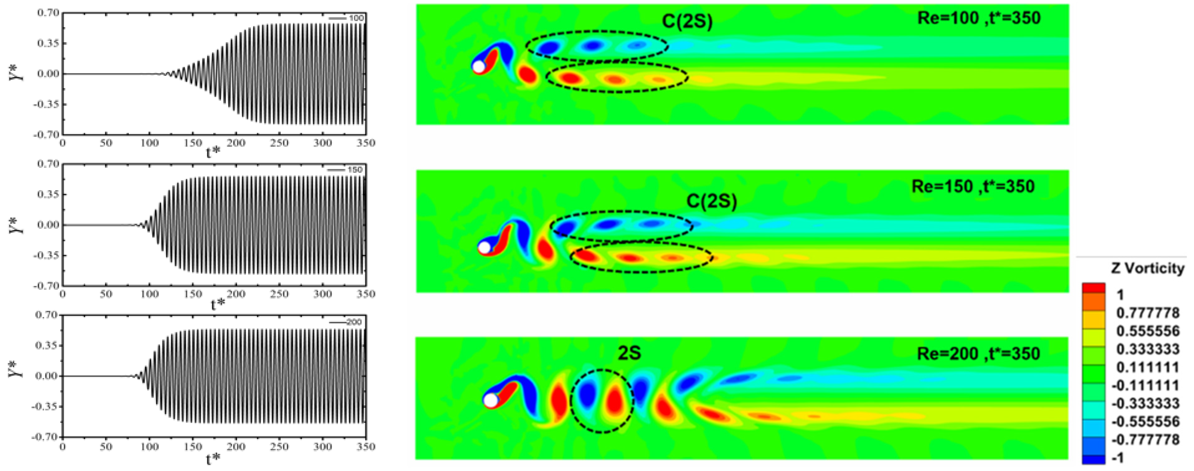
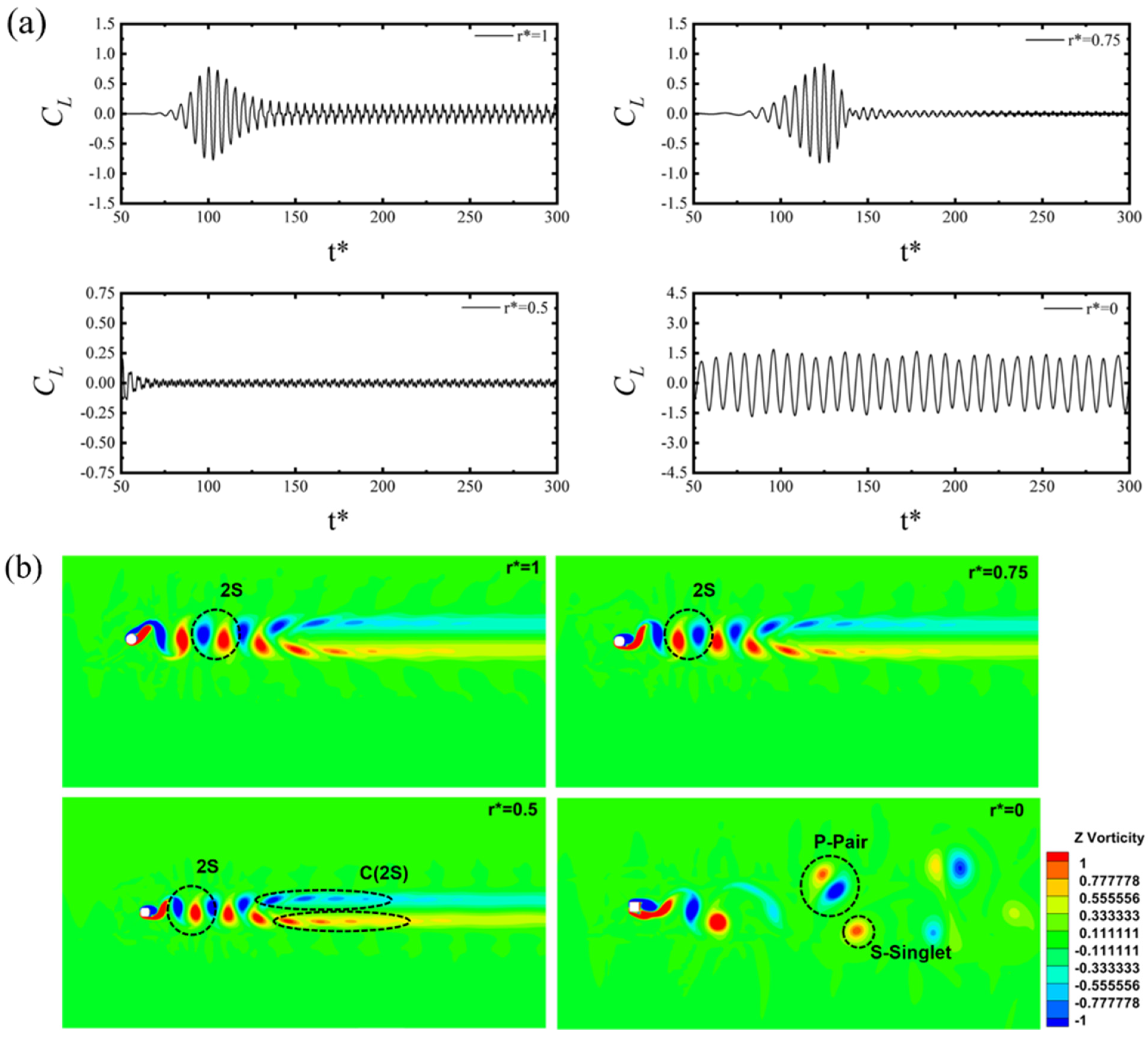
  • Maximum vibrational amplitude was observed for the circular cylinder (r* = 1) and Re = 100 due to lock-in synchronization being present for this specific case. Natural frequency ( f n ) and vibrational frequency ( f * ) overlapped and led to a high vibration amplitude. This vibration persisted for the circular cylinder with an increasing Reynolds number.
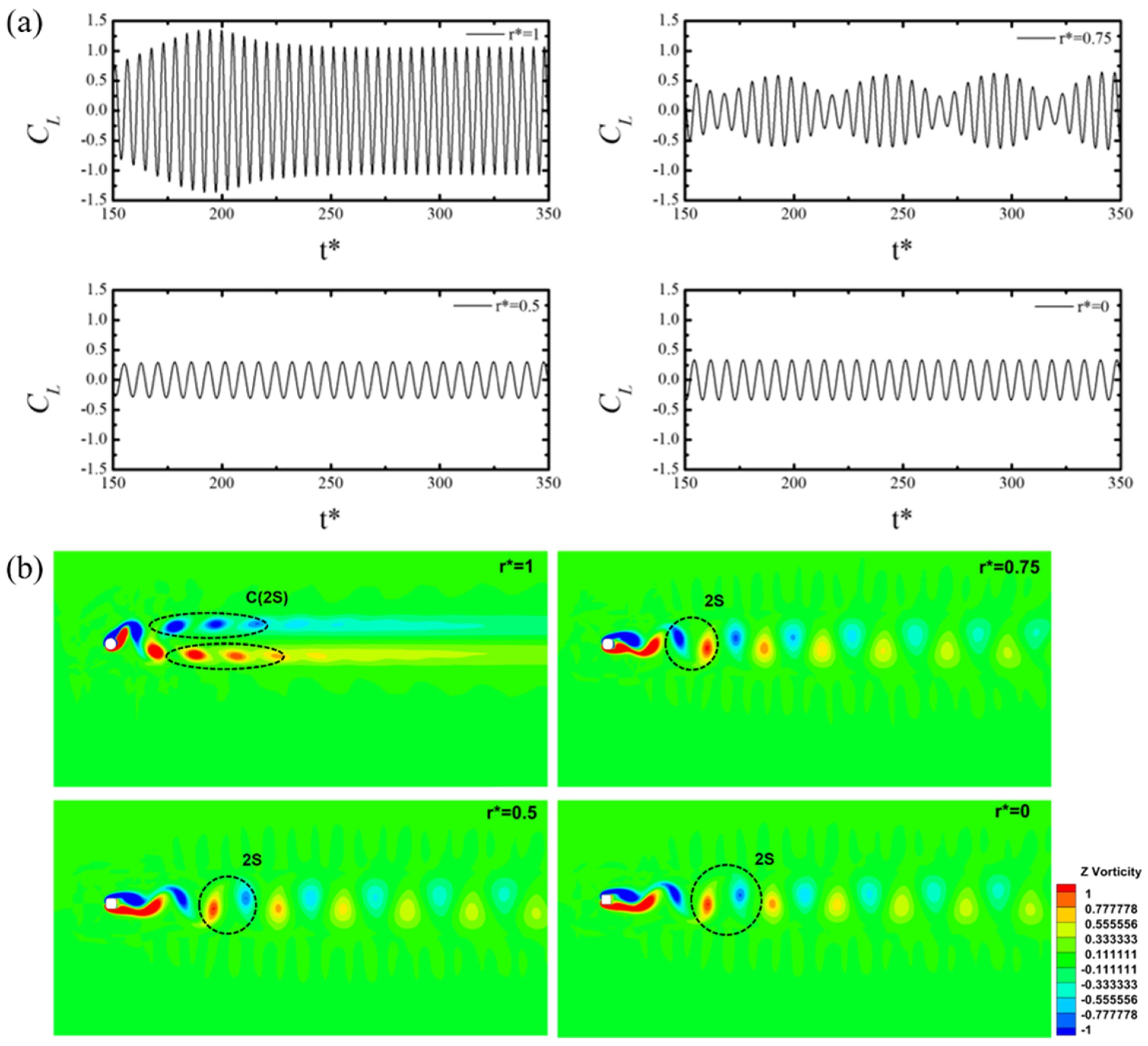
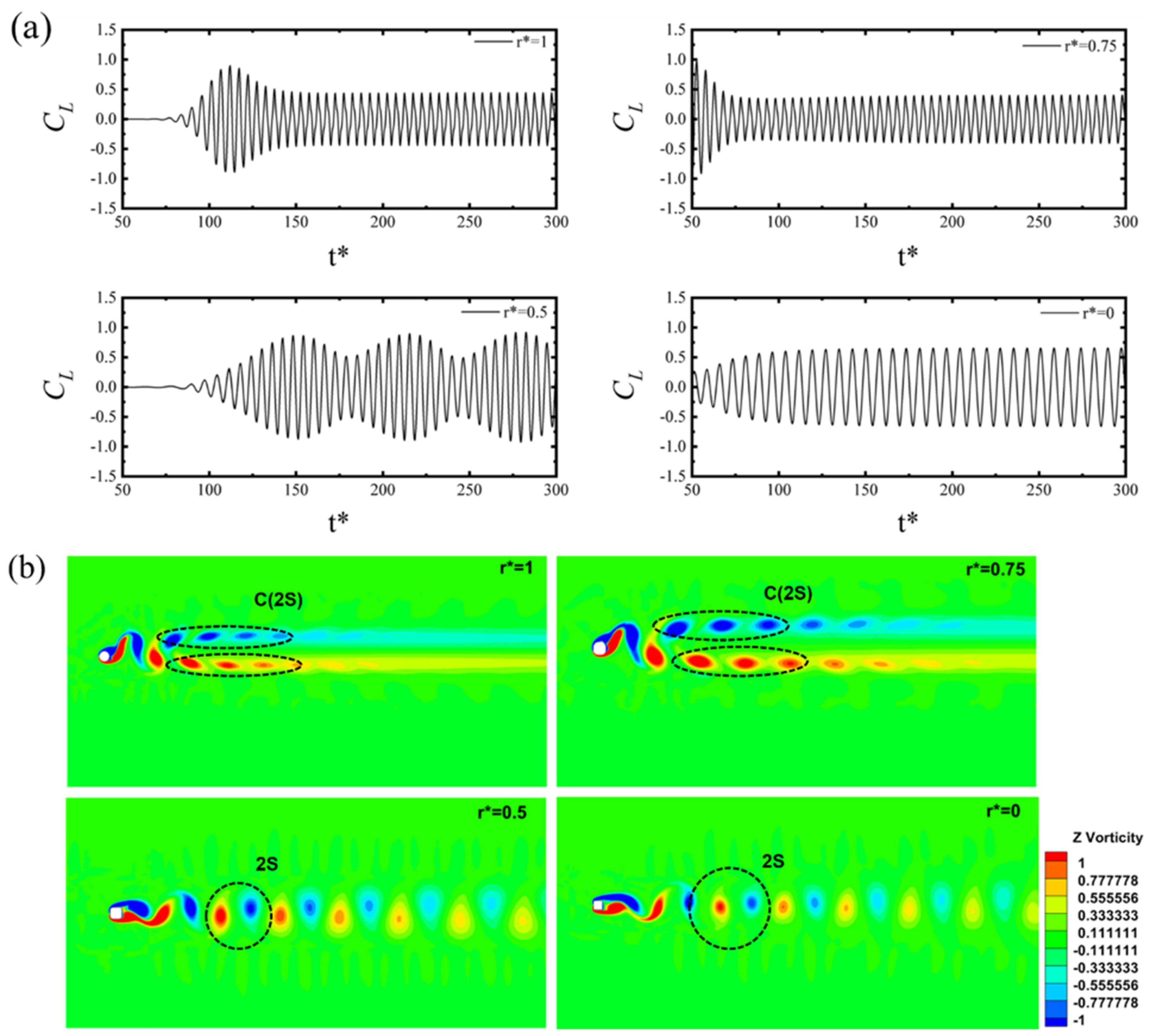
  • As the Reynolds number increased, a shift from C(2S) to 2S vortex shedding was observed. The value of the Strouhal number was reduced as the filleted radii were reduced from r* = 1 to 0 (square). The Strouhal number increased as the value of the Reynolds number increased for a constant corner radius r* = 0.5, 0.75, and 1. P+S vortex shedding was observed at a higher Reynolds number for the square cylinder.
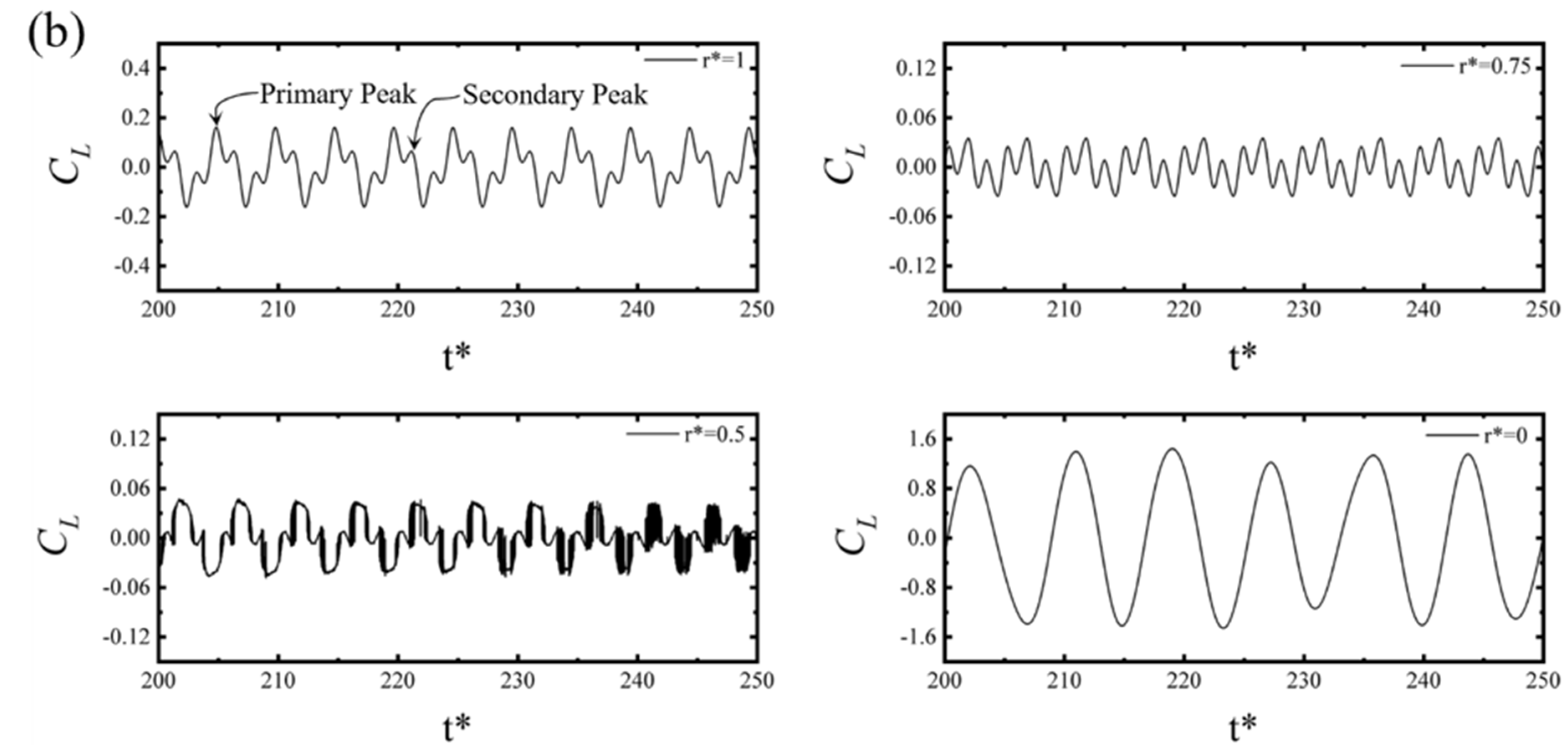
  • Four characteristic oscillation modes could be identified: Mode-I with small oscillation amplitude; mode-II with fluctuating oscillation amplitude known as hysteresis (Beating); mode-III where the amplitude is at the maximum because of lock-in synchronization (i.e., vortex shedding frequency equal to the natural frequency); and mode-IV, constant oscillation amplitude.
  • A key conclusion from the study was that a shift happened due to the change in corner radii. The beating phenomenon (mode-II) for the circular cylinder that occurred at Re = 75–85 now occurred at Re = 100 for r* = 0.75, Re = 150 for r* = 0.5, and Re = 200 for r* = 0. Mode-I did not occur for r* = 1, while it occurred for r* = 0.5 at Re = 100 and r* = 0 at Re = 100 and 150.
  • The minimum drag coefficient C D ¯ and lift coefficient C L was observed for r* = 0.5 and Re = 150 as well as at r* = 0.5 and Re = 100, respectively, although the minimum C D ¯ was in the vibrational mode-II type. A / D was observed for r* = 0.5 and Re = 100, which was in vibrational mode-I type.
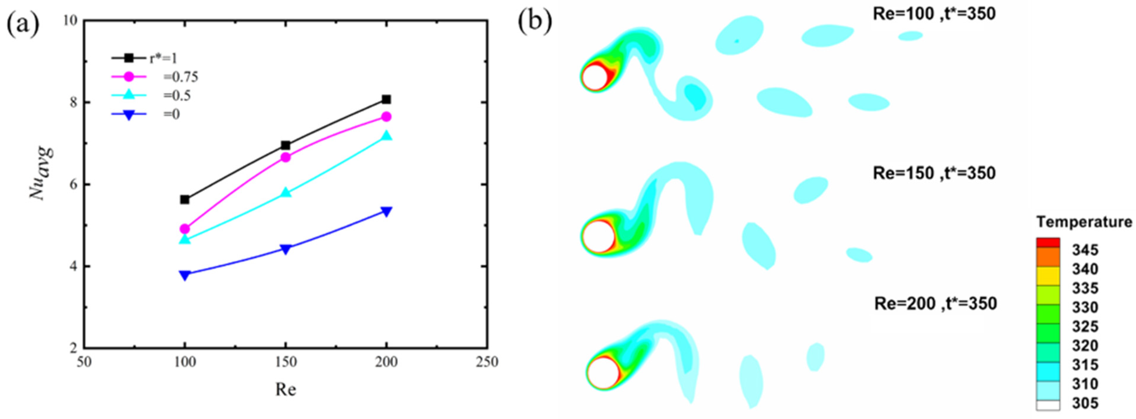
  • The Nusselt number mainly varied over three different Re values for all cases. N u a v g increased with Reynolds number and r*. Early separation of the boundary layer can reduce the heat transfer, which mitigated the value of the Nusselt number. Maximum and minimum average Nusselt numbers were observed for r* = 1 and Re = 200, and r* = 0 and Re = 200, respectively. They showed a dependence on the Reynold number, filleted radii, and type of flow around the cylinder.
  • The flow remained attached to the circular cylinder for a longer time than the square cylinder. A change of 47% in N u a v g at Re = 100 was observed. The maximum change for the square cylinder to circular cylinder occurred at Re = 150 for N u a v g . Separation occurring at the edge of the square cylinder caused a huge wake behind it, and the specific region value of N u a v g decreased rapidly.

5. Prospective Work

To extend this work, a new approach on studying the phases with the help of a neural network and machine learning will provide insights into the vortex dynamics.

Author Contributions

Conceptualization, M.I. and I.J.; Methodology, Y.S., M.I. and Y.F.; Validation, Y.S.; Investigation, M.I., Y.F. and I.J.; Data curation, Y.S.; Writing—original draft, Y.S.; Writing—review & editing, M.I., Y.F. and I.J.; Visualization, Y.S.; Supervision, M.I., Y.F. and I.J.; Funding acquisition, M.I. All authors have read and agreed to the published version of the manuscript.

Funding

This research was sponsored by Khalifa University of Science and Technology (Grant CIRA-2020-057).

Institutional Review Board Statement

Not Applicable.

Informed Consent Statement

Not Applicable.

Conflicts of Interest

The authors declare no conflict of interest.

Nomenclature

A Maximum Amplitude
c Damping Coefficient
C D ¯ Average Coefficient of Drag
C D m a x Maximum Coefficient of Drag
C L Coefficient of Lift
c p Specific Heat Capacity
D Diameter of cylinder
f n Natural Frequency
F n Normalized Natural Frequency
f s , f * Frequency of Oscillation
k Spring Constant
m Mass
m * Mass Ratio
N H c Non-Heated Cylinder
N u a v g Average Nusselt Number
N u Nusselt Number
p Pressure
P r Prandtl Number
r * = r R Fillet Corner (r is the radius of the corner, R is the radius of the Cylinder)
R e Reynolds number
T Flow Temperature
T S Surface Temperature
S t Strouhal Number
U r Reduced Velocity
U Free Stream Velocity
Y * Y-direction Amplitude
ρ Density
μ Viscosity
λ Thermal Conductivity
ξ Damping Ratio

References

  1. Feng, C.C. The Measurement of Vortex Induced Effects in Flow Past Stationary and Oscillating Circular and D-Section Cylinders. Ph.D. Thesis, University of British Columbia, Vancouver, BC, Canada, 1968. [Google Scholar] [CrossRef]
  2. Jauvtis, N.; Williamson, C.H.K. Vortex-Induced Vibration of a Cylinder with Two Degrees of Freedom. J. Fluids Struct. 2003, 17, 1035–1042. [Google Scholar] [CrossRef]
  3. Sarpkaya, T. A Critical Review of the Intrinsic Nature of Vortex-Induced Vibrations. J. Fluids Struct. 2004, 19, 389–447. [Google Scholar] [CrossRef]
  4. Williamson, C.H.K.; Govardhan, R. VORTEX-INDUCED VIBRATIONS. Annu. Rev. Fluid Mech. 2004, 36, 413–455. [Google Scholar] [CrossRef] [Green Version]
  5. Khalak, A.; Williamson, C.H.K. Investigation of Relative Effects of Mass and Damping in Vortex-Induced Vibration of a Circular Cylinder. J. Wind Eng. Ind. Aerodyn. 1997, 69–71, 341–350. [Google Scholar] [CrossRef]
  6. Williamson, C.H.K.; Roshko, A. Vortex Formation in the Wake of an Oscillating Cylinder. J. Fluids Struct. 1988, 2, 355–381. [Google Scholar] [CrossRef]
  7. Brika, D.; Laneville, A. Vortex-Induced Vibrations of a Long Flexible Circular Cylinder. J. Fluid Mech. 1993, 250, 481–508. [Google Scholar] [CrossRef]
  8. Shiels, D.; Leonard, A.; Roshko, A. Flow-induced vibration of a circular cylinder at limiting structural parameters. J. Fluids Struct. 2001, 15, 3–21. [Google Scholar] [CrossRef]
  9. Robertson, I.; Li, L.; Sherwin, S.J.; Bearman, P.W. A Numerical Study of Rotational and Transverse Galloping Rectangular Bodies. J. Fluids Struct. 2003, 17, 681–699. [Google Scholar] [CrossRef]
  10. Alam, M.M. Effects of Mass and Damping on Flow-Induced Vibration of a Cylinder Interacting with the Wake of Another Cylinder at High Reduced Velocities. Energies 2021, 14, 5148. [Google Scholar] [CrossRef]
  11. Kumar, D.; Sen, S. Flow-Induced Vibrations of a Pair of in-Line Square Cylinders. Phys. Fluids 2021, 33, 043602. [Google Scholar] [CrossRef]
  12. Ajith Kumar, R.; Sohn, C.H.; Gowda, B.H.L. Influence of Corner Radius on the near Wake Structure of a Transversely Oscillating Square Cylinder. J. Mech. Sci. Technol. 2009, 23, 2390–2416. [Google Scholar] [CrossRef]
  13. Hu, J.; Zhou, Y.; Dalton, C. Effects of the Corner Radius on the near Wake of a Square Prism. Exp. Fluids 2006, 40, 106–118. [Google Scholar] [CrossRef]
  14. Miran, S.; Sohn, C.H. Numerical Study of the Rounded Corners Effect on Flow Past a Square Cylinder. Int. J. Numer. Methods Heat Fluid Flow 2015, 25, 686–702. [Google Scholar] [CrossRef]
  15. Adeeb, E.; Haider, B.A.; Sohn, C.H. Influence of Rounded Corners on Flow Interference between Two Tandem Cylinders Using FVM and IB-LBM. Int. J. Numer. Methods Heat Fluid Flow 2018, 28, 1648–1663. [Google Scholar] [CrossRef]
  16. Zhao, H.; Zhao, M. Effect of Rounded Corners on Flow-Induced Vibration of a Square Cylinder at a Low Reynolds Number of 200. Ocean Eng. 2019, 188, 106263. [Google Scholar] [CrossRef]
  17. Sen, S.; Mittal, S. Free Vibration of a Square Cylinder at Low Reynolds Numbers. J. Fluids Struct. 2011, 27, 875–884. [Google Scholar] [CrossRef]
  18. Ghozlani, B.; Hafsia, Z.; Maalel, K. Numerical Study of Flow around an Oscillating Diamond Prism and Circular Cylinder at Low Keulegan-Carpenter Number. J. Hydrodyn. 2012, 24, 767–775. [Google Scholar] [CrossRef]
  19. Wu, B.; Li, S.; Li, K.; Yang, Q.; Zhang, L.; Qian, G. Large-Eddy Simulation of the near Wake of a 5:1 Rectangular Cylinder in Oscillating Flows at Re=670. J. Wind Eng. Ind. Aerodyn. 2020, 196, 104050. [Google Scholar] [CrossRef]
  20. Vijay, K.; Srinil, N.; Zhu, H.; Bao, Y.; Zhou, D.; Han, Z. Flow-Induced Transverse Vibration of an Elliptical Cylinder with Different Aspect Ratios. Ocean Eng. 2020, 214, 107831. [Google Scholar] [CrossRef]
  21. Zhao, J.; Hourigan, K.; Thompson, M.C. Dynamic Response of Elliptical Cylinders Undergoing Transverse Flow-Induced Vibration. J. Fluids Struct. 2019, 89, 123–131. [Google Scholar] [CrossRef]
  22. Ding, L.; Zou, Q.; Zhang, L.; Wang, H. Research on Flow-Induced Vibration and Energy Harvesting of Three Circular Cylinders with Roughness Strips in Tandem. Energies 2018, 11, 2977. [Google Scholar] [CrossRef] [Green Version]
  23. Zhao, W.; Xue, F.; Shu, G.; Liu, M.; Lin, L.; Wang, Z.; Xiao, Z. Analysis of Flow-Induced Vibration of Steam Generator Tubes Subjected to Cross Flow. Nucl. Eng. Des. 2014, 275, 375–381. [Google Scholar] [CrossRef]
  24. Ali, U.; Islam, M.; Janajreh, I.; Fatt, Y.; Alam, M. Flow-Induced Vibrations of Single and Multiple Heated Circular Cylinders: A Review. Energies 2021, 14, 8496. [Google Scholar] [CrossRef]
  25. Goyder, H.G.D. Flow-Induced Vibration in Heat Exchangers. Chem. Eng. Res. Des. 2002, 80, 226–232. [Google Scholar] [CrossRef]
  26. Sun, X.; Ye, Z.; Li, J.; Wen, K.; Tian, H. Forced Convection Heat Transfer from a Circular Cylinder with a Flexible Fin. Int. J. Heat Mass Transf. 2019, 128, 319–334. [Google Scholar] [CrossRef]
  27. Izadpanah, E.; Amini, Y.; Ashouri, A. A Comprehensive Investigation of Vortex Induced Vibration Effects on the Heat Transfer from a Circular Cylinder. Int. J. Therm. Sci. 2018, 125, 405–418. [Google Scholar] [CrossRef]
  28. Alam, M.; Abdelhamid, T.; Islam, M. Heat Transfer and Flow around Cylinder: Effect of Corner Radius and Reynolds Number. Int. J. Heat Mass Transf. 2021, 171, 121105. [Google Scholar] [CrossRef]
  29. Kumar, A.; Dhiman, A.; Baranyi, L. Fluid Flow and Heat Transfer around a Confined Semi-Circular Cylinder: Onset of Vortex Shedding and Effects of Reynolds and Prandtl Numbers. Int. J. Heat Mass Transf. 2016, 102, 417–425. [Google Scholar] [CrossRef] [Green Version]
  30. Mahír, N.; Altaç, Z. Numerical Investigation of Convective Heat Transfer in Unsteady Flow Past Two Cylinders in Tandem Arrangements. Int. J. Heat Fluid Flow 2008, 29, 1309–1318. [Google Scholar] [CrossRef]
  31. Willden, R.H.J.; Graham, J.M.R. Three Distinct Response Regimes for the Transverse Vortex-Induced Vibrations of Circular Cylinders at Low Reynolds Numbers. J. Fluids Struct. 2006, 22, 885–895. [Google Scholar] [CrossRef]
  32. Sharma, A.; Eswaran, V. Heat and fluid flow across a square cylinder in the two-dimensional laminar flow regime. Numer. Heat Transf. Part A Appl. 2004, 45, 247–269. [Google Scholar] [CrossRef]
  33. Singh, S.P.; Mittal, S. Vortex-Induced Oscillations at Low Reynolds Numbers: Hysteresis and Vortex-Shedding Modes. J. Fluids Struct. 2005, 20, 1085–1104. [Google Scholar] [CrossRef]
  34. Zhao, J.; Leontini, J.S.; Lo Jacono, D.; Sheridan, J. Fluid–Structure Interaction of a Square Cylinder at Different Angles of Attack. J. Fluid Mech. 2014, 747, 688–721. [Google Scholar] [CrossRef]
  35. Alam, M. A Note on Flow-Induced Force Measurement of Oscillating Cylinder by Loadcell. Ocean Eng. 2022, 245, 110538. [Google Scholar] [CrossRef]
  36. Bhatt, R.; Alam, M.M. Vibrations of a Square Cylinder Submerged in a Wake. J. Fluid Mech. 2018, 853, 301–332. [Google Scholar] [CrossRef]
  37. Li, M.; Li, Q.; Shi, H.; Li, M. Effects of Free-Stream Turbulence on the near Wake Flow and Aerodynamic Forces of a Square Cylinder. J. Fluids Struct. 2022, 114, 103748. [Google Scholar] [CrossRef]
  38. Zheng, Z.C.; Zhang, N. Frequency Effects on Lift and Drag for Flow Past an Oscillating Cylinder. J. Fluids Struct. 2008, 24, 382–399. [Google Scholar] [CrossRef]
  39. Mittal, S.; Prasanth, T.K.; Behara, S.; Singh, S.P.; Kumar, R. Effect of Blockage on Vortex-Induced Vibrations at Low Reynolds Numbers. J. Fluids Struct. 2006, 22, 865–876. [Google Scholar] [CrossRef]
  40. Alam, M.; Abdelhamid, T.; Sohankar, A. Effect of Cylinder Corner Radius and Attack Angle on Heat Transfer and Flow Topology. Int. J. Mech. Sci. 2020, 175, 105566. [Google Scholar] [CrossRef]
  41. Zhang, W.; Chen, X.; Yang, H.; Liang, H.; Wei, Y. Forced Convection for Flow across Two Tandem Cylinders with Rounded Corners in a Channel. Int. J. Heat Mass Transf. 2019, 130, 1053–1069. [Google Scholar] [CrossRef]
  42. Dhiman, A.K.; Chhabra, R.P.; Sharma, A.; Eswaran, V. Effects of Reynolds and Prandtl Numbers on Heat Transfer Across a Square Cylinder in the Steady Flow Regime. Numer. Heat Transf. Part A Appl. 2006, 49, 717–731. [Google Scholar] [CrossRef]
  43. Dwivedi, A.R.; Dhiman, A.K. Flow and Heat Transfer Analysis around Tandem Cylinders: Critical Gap Ratio and Thermal Cross-Buoyancy. J. Braz. Soc. Mech. Sci. Eng. 2019, 41, 487. [Google Scholar] [CrossRef]
  44. Rakhsha, M.; Kees, C.E.; Negrut, D. Lagrangian vs. Eulerian: An Analysis of Two Solution Methods for Free-Surface Flows and Fluid Solid Interaction Problems. Fluids 2021, 6, 460. [Google Scholar] [CrossRef]
  45. de Moraes, P.G.; Alcântara Pereira, L.A. Surface Roughness Effects on Flows Past Two Circular Cylinders in Tandem Arrangement at Co-Shedding Regime. Energies 2021, 14, 8237. [Google Scholar] [CrossRef]
Figure 1. (a) Spring-damper model of an oscillating cylinder. (b) Changing corner radius ratio moving from square to the circular cylinder. (c) Computational domain with a fine grid structure and zoomed-in view of grids around the square cylinder.
Energies 15 09145 g001
Figure 2. Frequency response of a circular cylinder at different Re = 100, 150, 200.On the x-axis, the frequency response is denoted, the y-axis shows the power spectrum density (PSD), and the z-axis shows different Re values.
Energies 15 09145 g002
Figure 3. Effect of Re on Y * and Z-vorticity at 100, 150, and 200 for 350.
Energies 15 09145 g003
Figure 4. Effect of r * on vortex-induced vibration at different Re: (a) A D vs. Re, (b) C D   ¯ vs. Re, (c) C L vs. Re, (d) S t vs. Re.
Energies 15 09145 g004
Figure 5. Effect of r * on vortex-induced vibration at Re = 100 and U r = 4.92 . (a) Time histories of lift coefficient. (b) Flow field at different radius corners. (c) Phase diagrams illustrating the displacement vs. lift coefficient.
Energies 15 09145 g005aEnergies 15 09145 g005b
Figure 6. Effect of r* on vortex-induced vibration at Re = 150 and U r = 4.92 (a) Time histories of lift coefficient. (b) The flow field of different radius corners. (c) Phase diagrams illustrating the displacement vs. lift coefficient.
Energies 15 09145 g006aEnergies 15 09145 g006b
Figure 7. Effect of r * on vortex-induced vibration at Re =2 00 and U r = 4.92 . (a) Time histories of the lift coefficient. (b) Flow field of different radius corners. (c) Phase diagrams illustrating the displacement vs. lift coefficient.
Energies 15 09145 g007aEnergies 15 09145 g007b
Figure 8. Pictorial representation of the streamlines representing the transition along the streamlines.
Energies 15 09145 g008
Figure 9. (a) Frequency response of free oscillating cylinders with varying corner radii and different Reynolds numbers from 100 to 200. (b) Time histories of Re = 200 with varying r*.
Energies 15 09145 g009aEnergies 15 09145 g009b
Figure 10. Effect of r* on heat transfer with vortex-induced vibration at different Re. (a) Average Nusselt number N u a v g vs. Re. (b) Temperature contour of the heated cylinder.
Energies 15 09145 g010
Figure 11. Effect of r* on heat transfer with vortex-induced vibration at Re = 100 and U r = 4.92 . (a) Time histories of the lift coefficient. (b) Temperature contour of the different radius corners.
Energies 15 09145 g011
Figure 12. Effect of r* on heat transfer with vortex-induced vibration at Re = 150 and U r = 4.92 . (a) Time histories of the lift coefficient. (b) Temperature contour of the different radius corners.
Energies 15 09145 g012
Figure 13. Effect of r* on heat transfer with vortex-induced vibration at Re = 200 and U r = 4.92 . (a) Time histories of the lift coefficient. (b) Temperature contour of the different radius corners.
Energies 15 09145 g013
Table 1. Vortex-induced vibration parameters for U r = 4.94 and Re = 100. Key parameters such as maximum amplitude, average drag coefficient, maximum drag coefficient, and lift coefficient are summarized in the table below.
MeshNodesStSt
%Error
A D A D
%Error
C D m a x C D m a x
%Error
C L , m a x C L , m a x
%Error
Grid-I (Coarse)153451.9005.0000.5752.5403.0104.5101.3603.560
Grid-II (Baseline)559820.1943.0000.5801.6942.9301.7361.3702.830
Grid-III (Fine-I)750090.19452.7500.5801.6942.9251.5601.3762.410
Grid-IV(Fine-II)1003220.1952.5000.5801.6942.9101.0401.3802.120
Singh and Mittal [33] 260200.200 0.590 2.88 1.41
Publisher’s Note: MDPI stays neutral with regard to jurisdictional claims in published maps and institutional affiliations.

