
New Technology of Pressure Relief Control in Soft Coal Roadways with Deep, Violent Mining and Large Deformation: A Key Study

 , , ,
, , ,
Abstract
:1. Introduction
2. Project Overview
2.1. Engineering Geology and Problems
2.2. Analysis of Control Difficulties of Roadway Surrounding Rock
- (1)
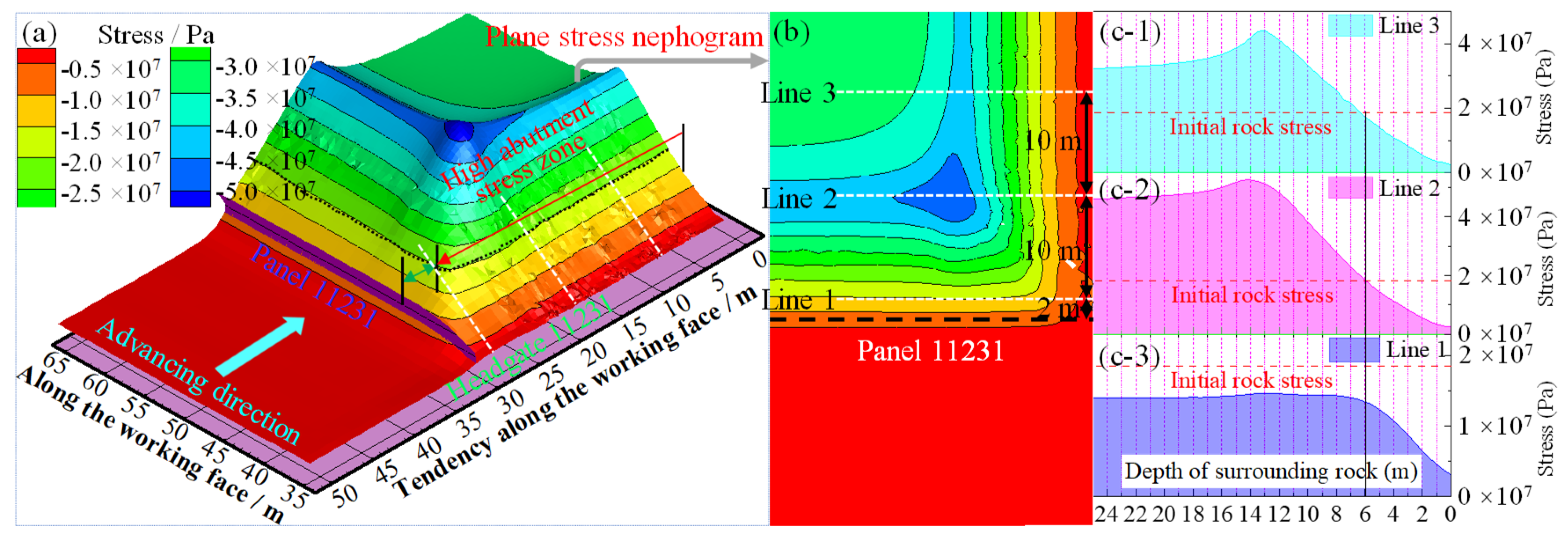
- High in situ stress. The average buried depth of headgate 11231 is 740 m, and the primary rock stress reaches 20 MPa. After roadway excavation, the shallow surrounding rock changed from a three-dimensional to a two-dimensional stress state. Moreover, the stress was redistributed, which increased the surrounding rock stress by two to three times at a certain depth. The surrounding rock of the roadway deteriorates rapidly owing to the high in situ stress and stress state change (as depicted in Figure 5a, the roadway in this section (near panel 11231) experiences deformation of surrounding rock dominated by vertical stress, which is mainly manifested in large roof subsidence).
- (2)
- Complex tectonic stress. The geological structure of the 1100 southern mining area is complex, and the tectonic stress caused by tectonic movement has a great influence on the stability of the roadway surrounding rock. As illustrated in Figure 5b, this section of the roadway (near panel 11231) undergoes deformation of surrounding rock dominated by tectonic stress, which is mainly manifested by the large amount of movement of the two ribs getting closer.
- (3)
- The coal body is soft and broken. The strength of the coal body in a coal mine is low, owing to the loose and soft properties of the coal body. The borehole peep (Figure 5c-I) shows that the coal body is broken when the roadway rib depth is 3 m. It can be seen from Figure 5c-II that when the roadway rib has no large deformation, the soft coal body in the roadway rib peels off under an effective support. The low strength and weak self-supporting capacity of the coal body is the main reason for the large deformation of headgate 11231.
- (4)
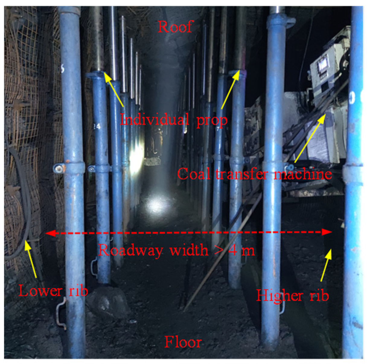
- The roadway section is large. Headgate 11231 has a center height of 3.5 m and a roadway width of 5 m. Research shows that the larger the roadway section, the easier it is to cause greater stress concentration, and the more serious the deformation and damage of the roadway surrounding rock. In addition, headgate 11231 is a trapezoidal roadway driven along the coal seam roof, and the height of the roadway panel rib (higher rib) reaches 4.2 m. The irregular cross-sectional shape causes the surrounding rock of the roadway to be subjected to unbalanced pressure, and the surrounding rock of the roadway undergoes asymmetric deformation. The displacement monitoring data show that the deformation of the higher rib of the headgate is larger than that of the non-panel rib (lower rib). As displayed in the curve data in Figure 4, the deformation of the higher rib accounts for 65.6 and 67.0% of the accumulated approach of the two ribs in the stage without and with dynamic pressure, respectively.
- (5)
- Strong influence of mining. The average mining height of panel 11231 is 4.5 m. As indicated in Figure 5e, although the goaf is filled with gangue, owing to the low compressed ratio and large mining height, the overburden movement is strong after mining, and the strong disturbance range of the panel is up to 90 m. The broken coal body of the roadway surrounding rock within the disturbance range can easily undergo large deformation.
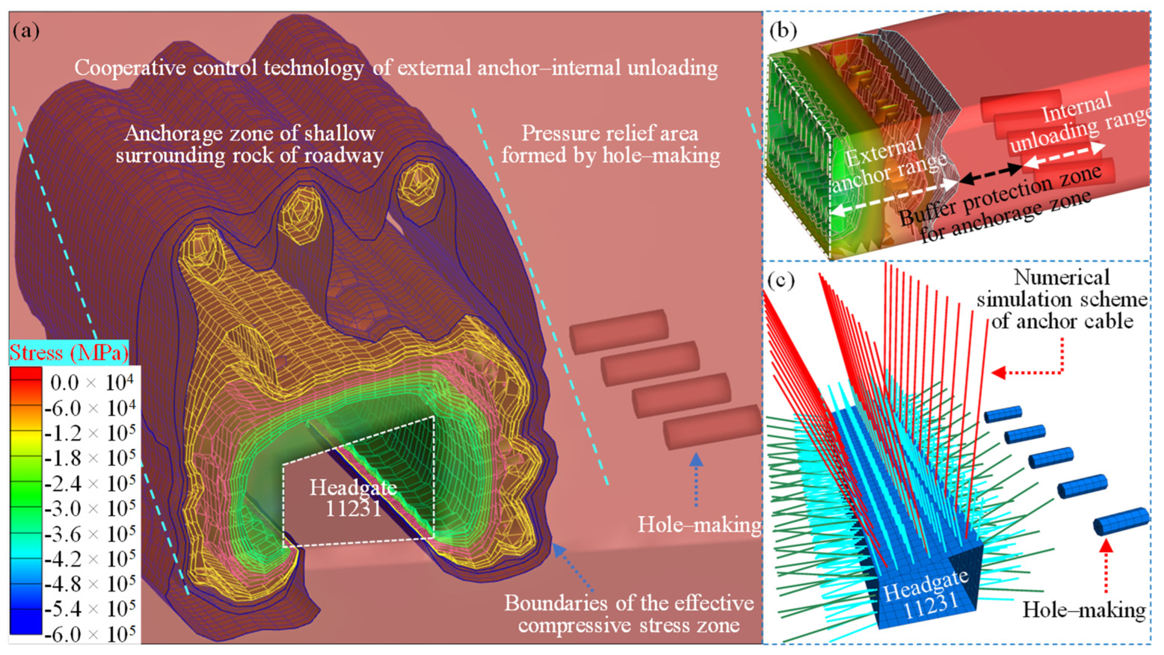
3. Principle and Key Technical Parameters of the Cooperative Control Technology of External Anchor–Internal Unloading of Coal Roadway Surrounding Rock
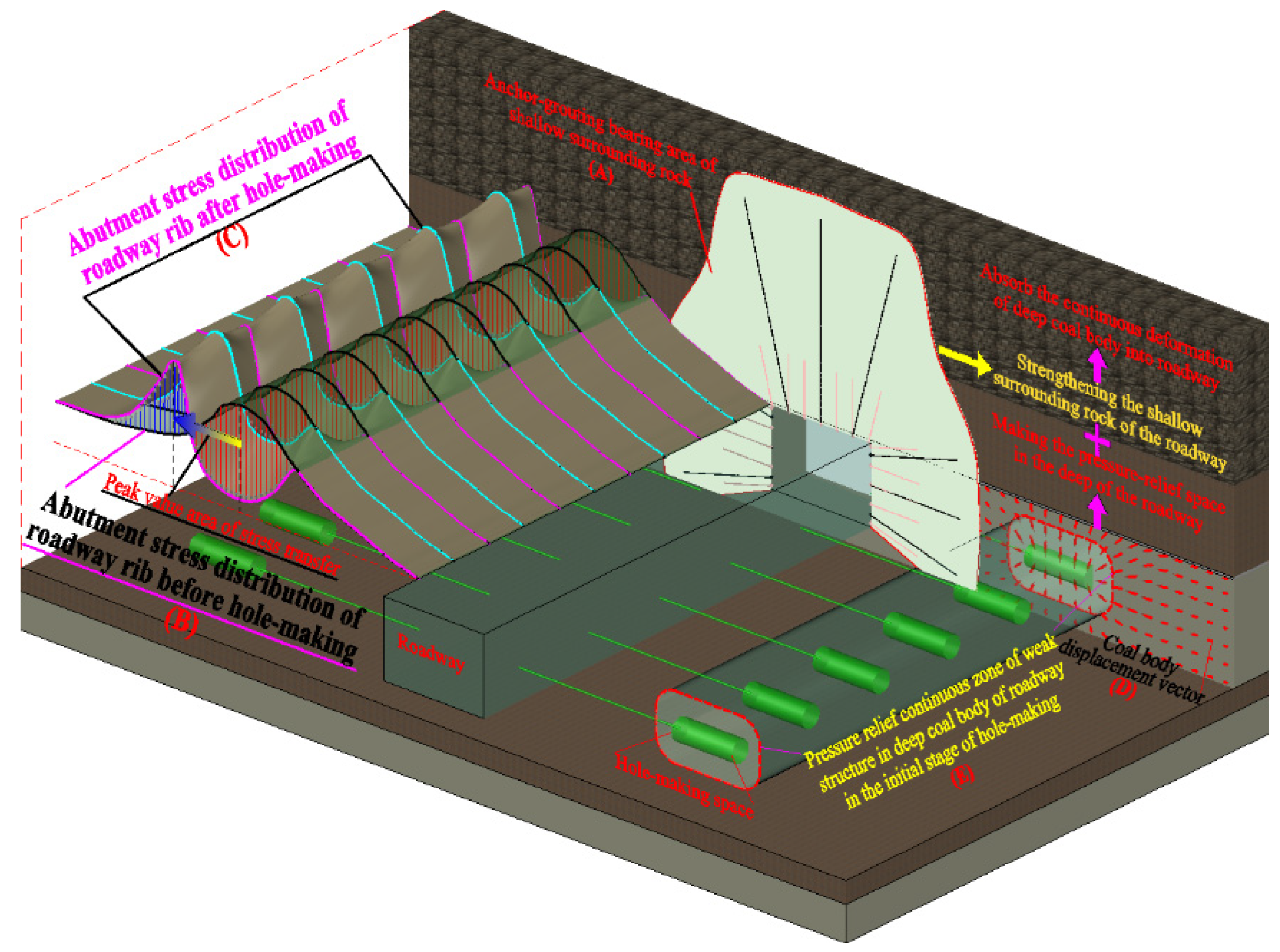
3.1. Principle of Cooperative Control Technology of External Anchor–Internal Unloading of Coal Roadway Surrounding Rock
3.2. Key Technical Parameters of Internal Hole-Making and Pressure Relief
- (1)
- Hole-making depth L1. The hole-making depth affects the abutment stress distribution of the roadway rib and the anchorage range of the shallow surrounding rock after the completion of roadway excavation. When the hole-making depth is extremely large, it cannot effectively relieve the pressure, and even more seriously, it may increase the stress peak in the shallow anchorage zone and affect the stability of the shallow surrounding rock. On the other hand, when the hole-making depth is extremely small, the stress transfer effect is not significant, and the hole-making space can easily cause damage to the shallow anchorage zone.
- (2)
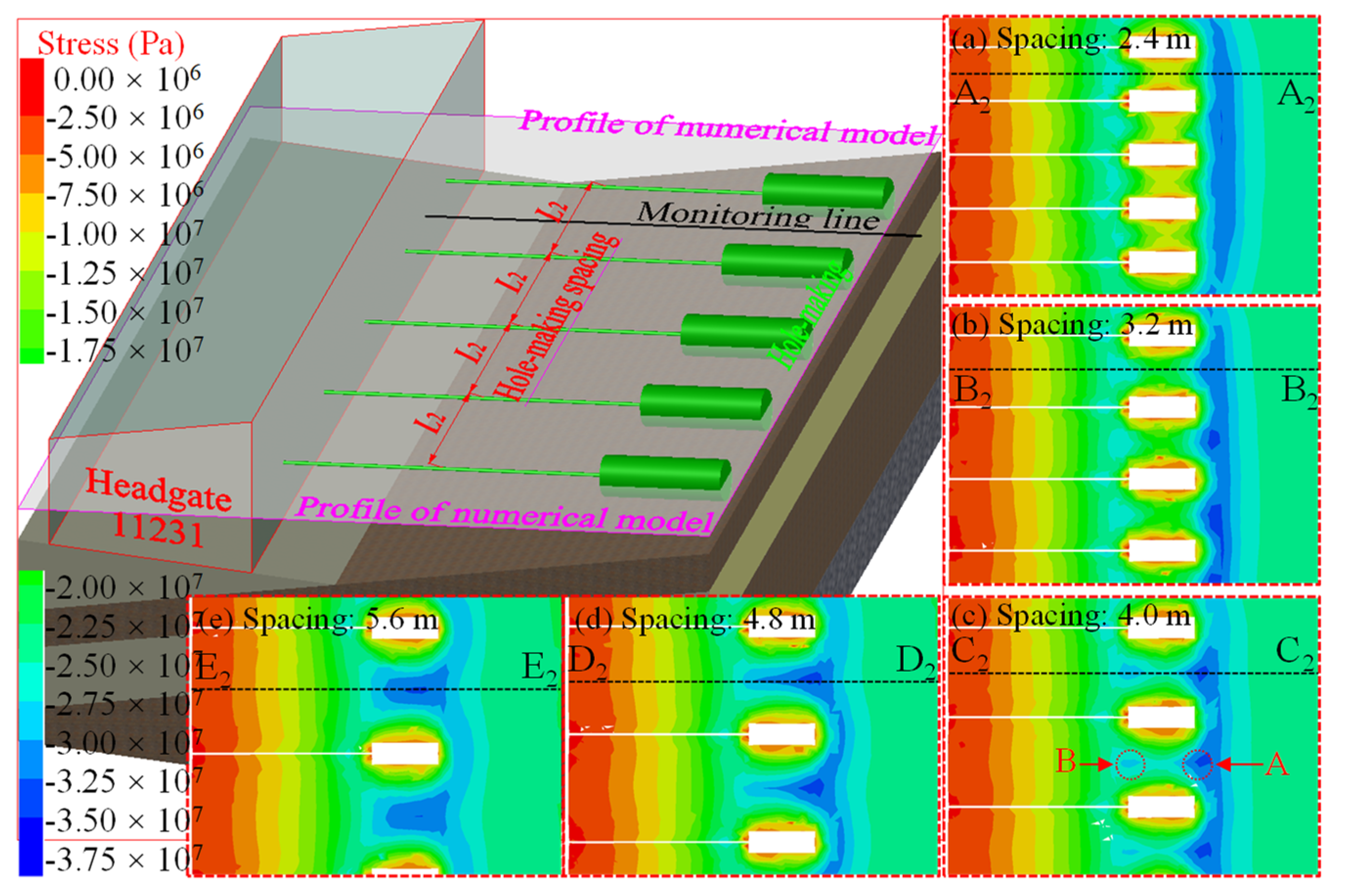
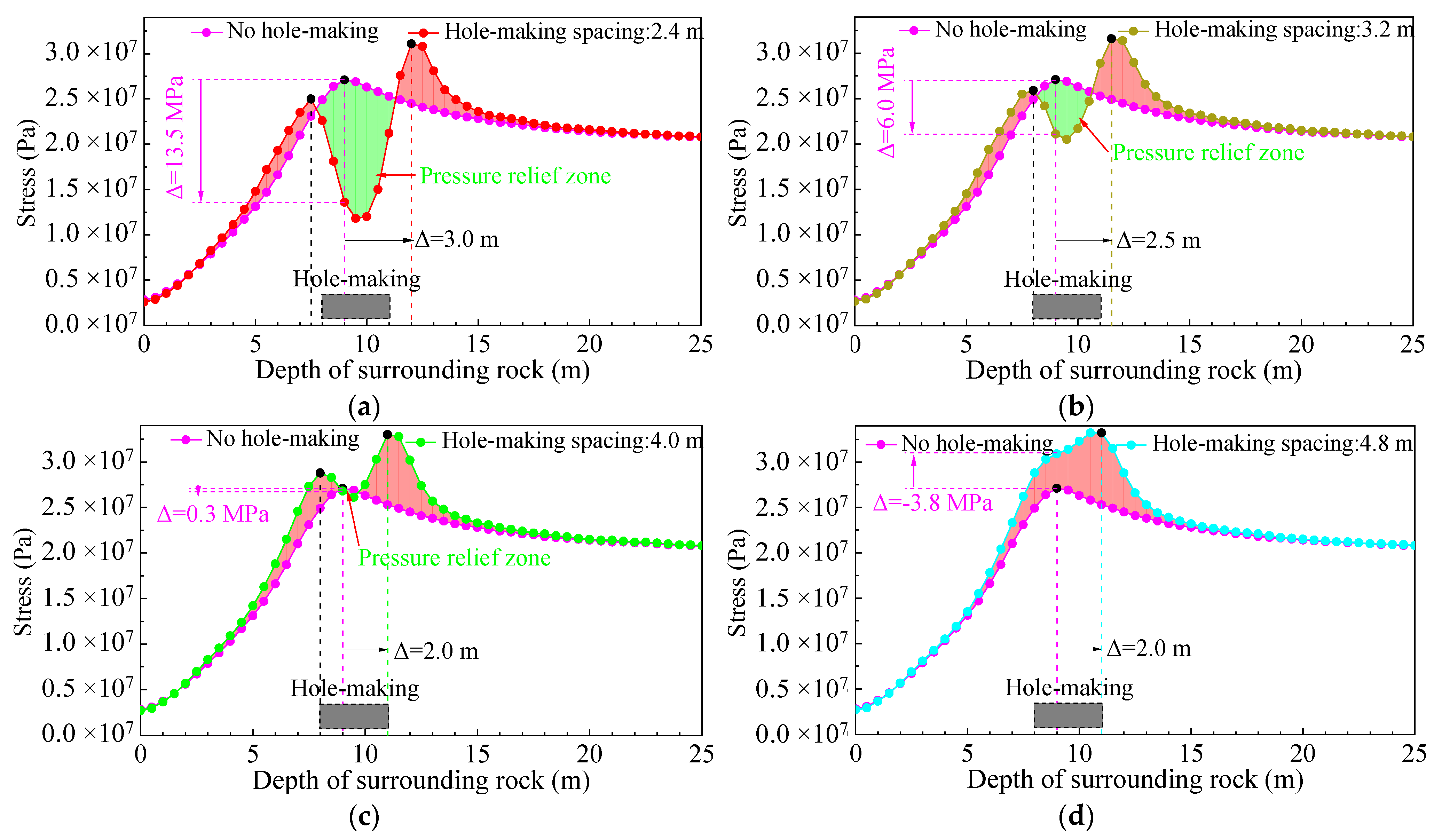
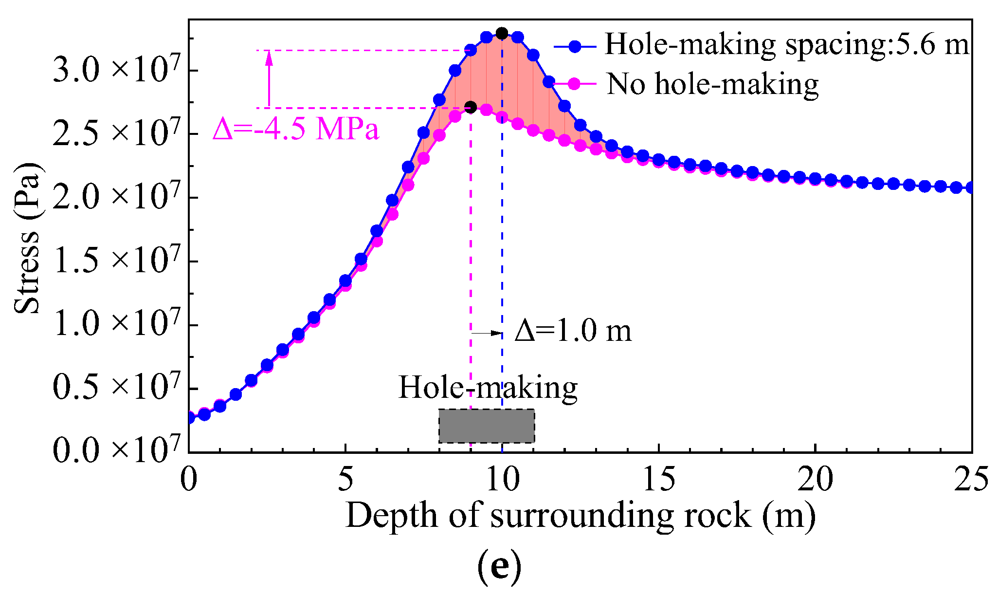
- Hole-making spacing L2. After the hole-making space is created, the coal body outside the hole-making space migrates to this space, forming a certain range of surrounding rock loose areas. Appropriate spacing of hole-makings can connect the loose areas of two adjacent holes-making along the axial direction of the roadway, and the loose areas of continuous hole-making connect with each other in the axial direction of the roadway to form a pressure relief continuous zone (Figure 6E). When the spacing is extremely large, the pressure relief continuous zone cannot be formed. In addition, the coal body between the hole-making spaces is still in a state of high concentrated stress, and the surrounding rock pressure relief effect is poor. In contrast, when the spacing is extremely small, dense ordinary boreholes cause great damage to the shallow surrounding rock, which affects its integrity, and at the same time increases the labor of workers and reduces construction efficiency.
- (3)
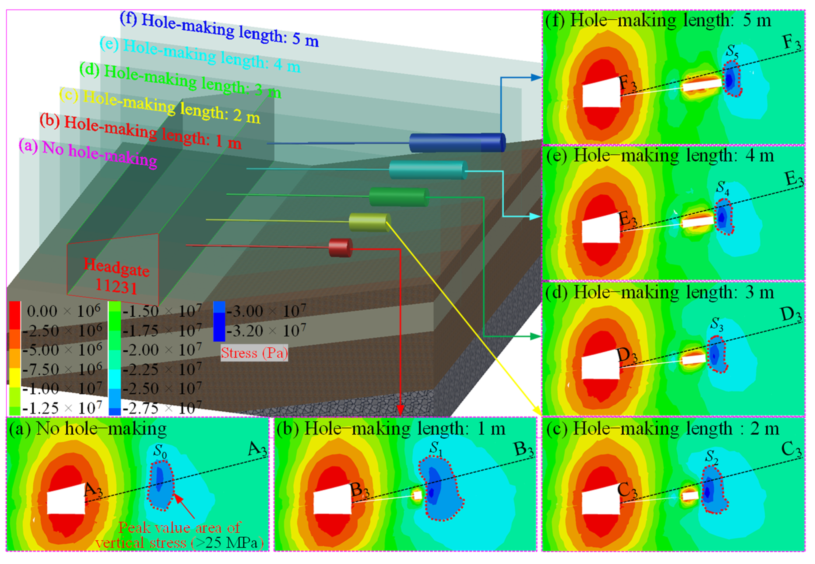
- Hole-making length L3. The hole-making length has a significant influence in terms of two aspects: (1) the greater the hole quantity and length, the greater the coal output and the more obvious the compensation effect of the hole-making space on deep coal; (2) pressure relief amplitude, namely, the transfer distance of highly concentrated stress. In general, when the hole-making depth is appropriate, the greater the hole-making length, the greater the transfer distance of the peak value of the roadway rib abutment stress to the deep rock. When the hole-making length is extremely small, the pressure relief range is small, the pressure relief effect is not sufficient, and the pressure relief hole-making is closed in a short time, preventing its blocking effect on the transfer of deep coal body to the roadway space. On the other hand, when the hole-making length is extremely large, the deeper hole-making space has little effect on the pressure relief of the shallow surrounding rock of the roadway.
4. Study on Key Technical Parameters of Pressure Relief by Internal Hole-Making
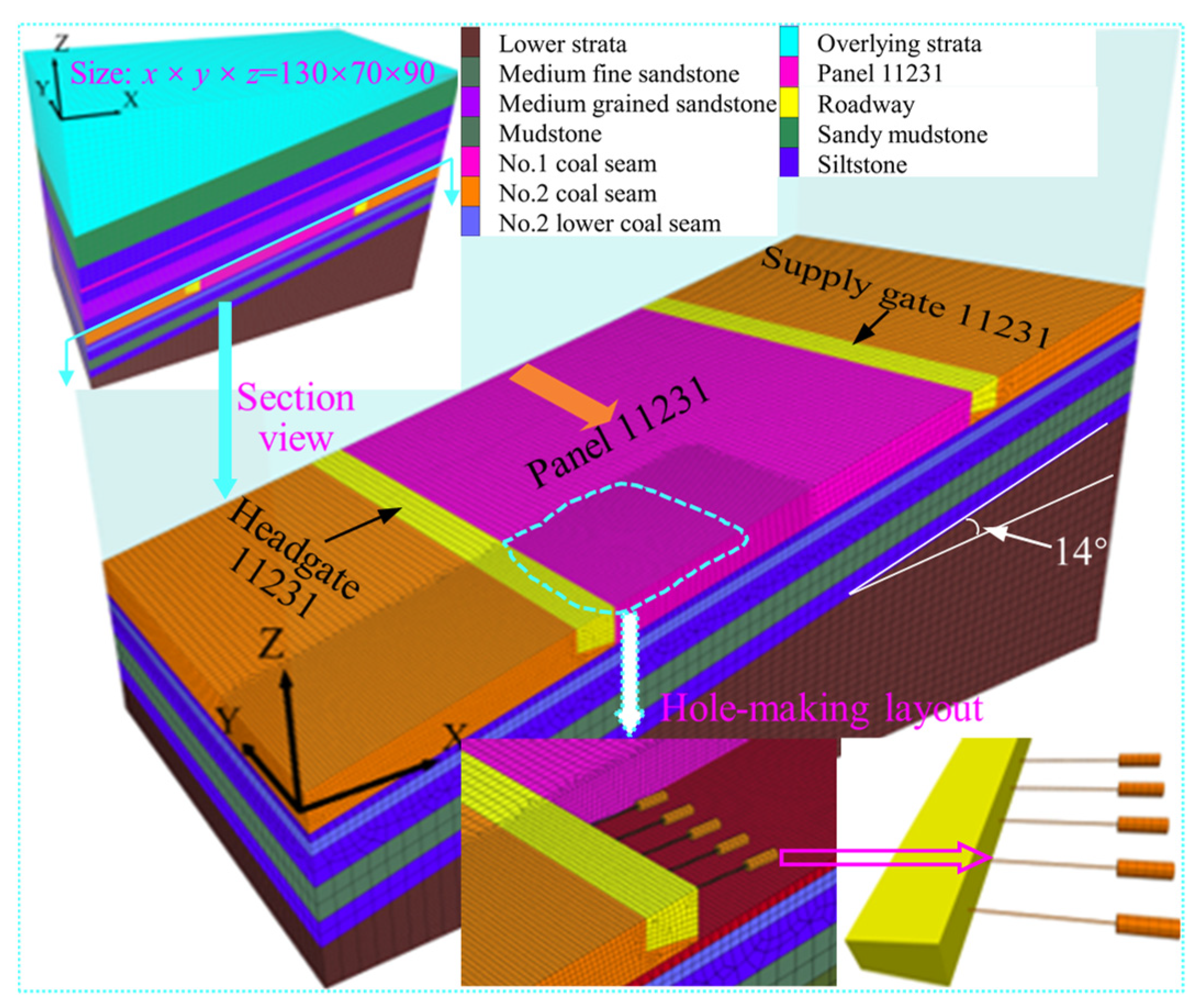
4.1. Establishment of Numerical Model and Research Ideas
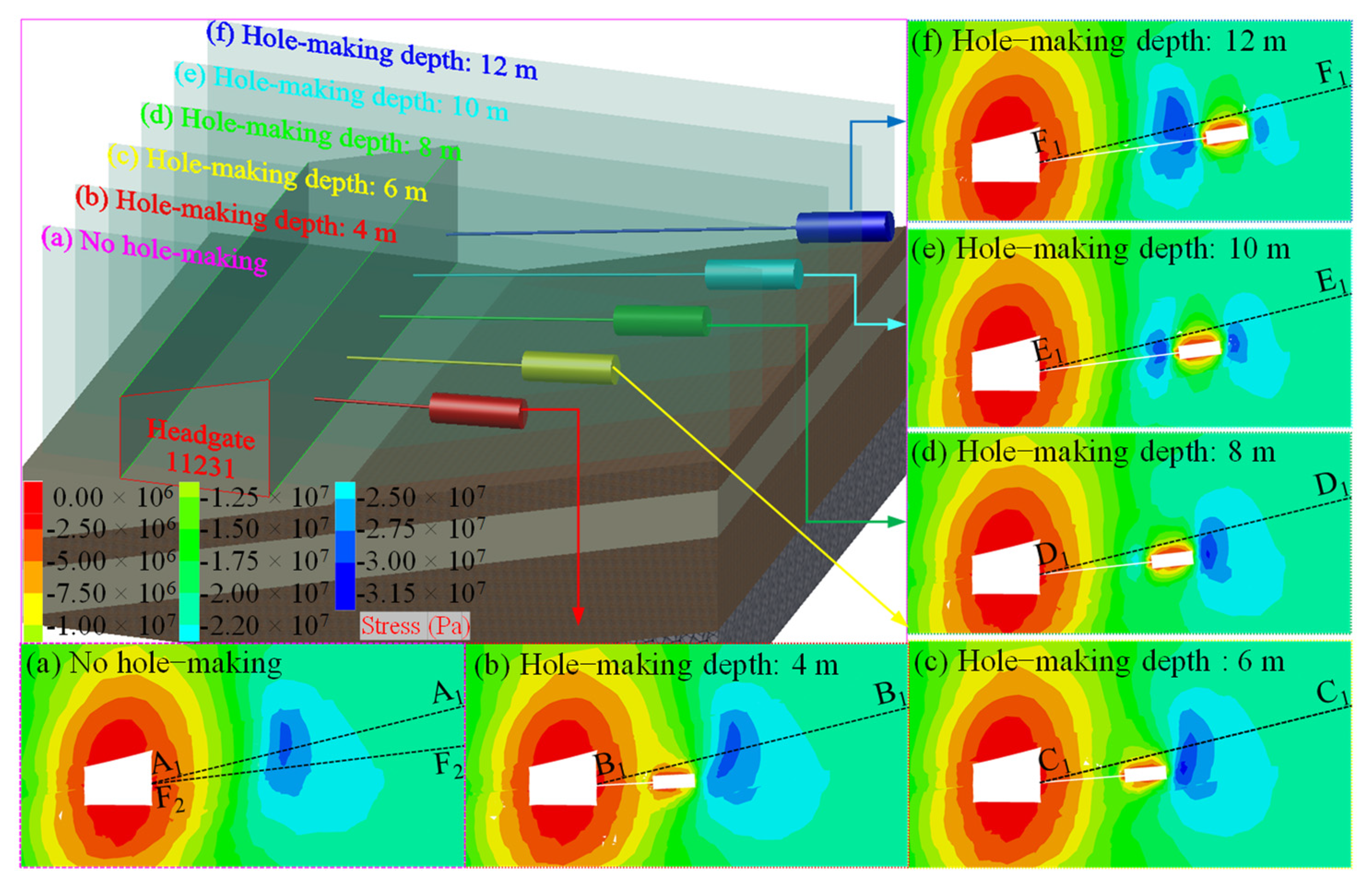
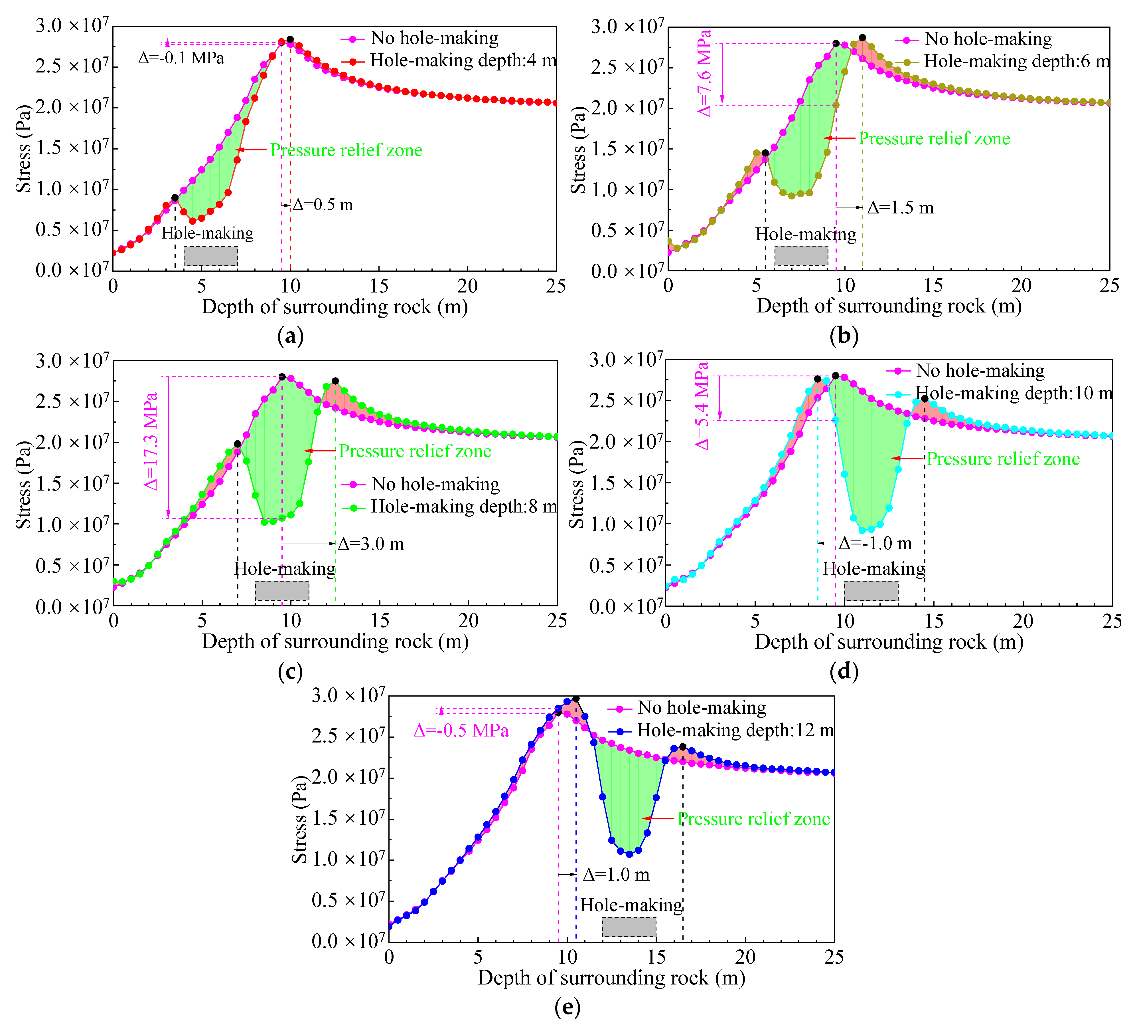
4.2. Key Technical Parameters of Pressure Relief by Internal Hole-Making in the No Mining Influence Stage
- (1)
- Hole-making depth
- (2)
- Hole-making spacing
- (3)
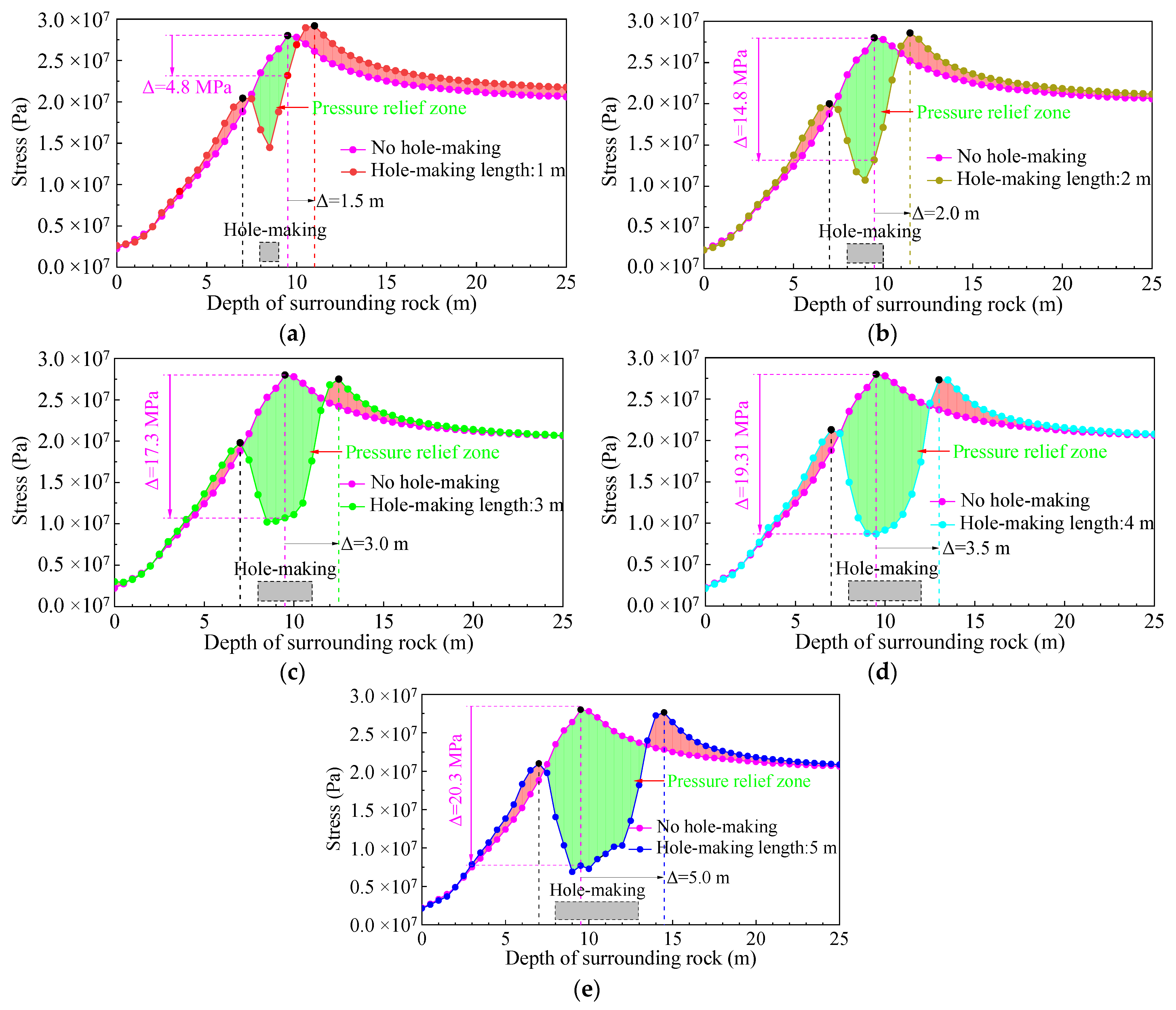
- Hole-making length
- (4)
- Research and analysis of key technical parameters
4.3. Optimization Analysis of Key Technical Parameters of Pressure Relief by Internal Hole-Making in the Mining Influence Stage
- (1)
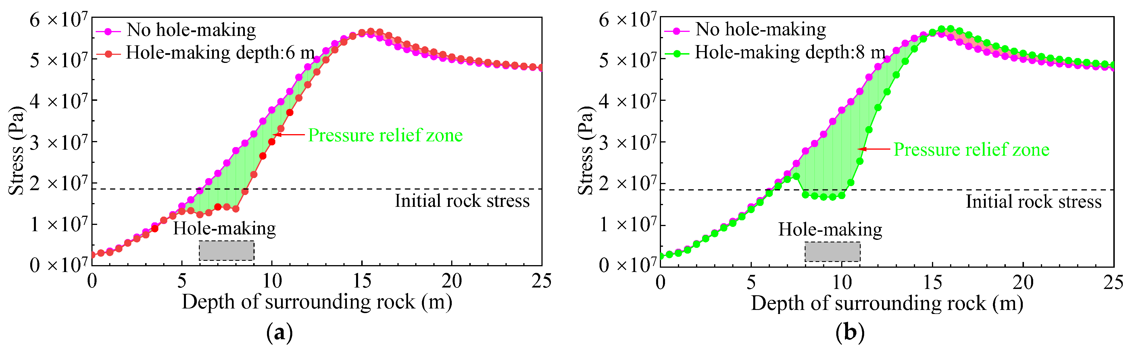
- Hole-making depth
- (2)
- Hole-making spacing
- (3)
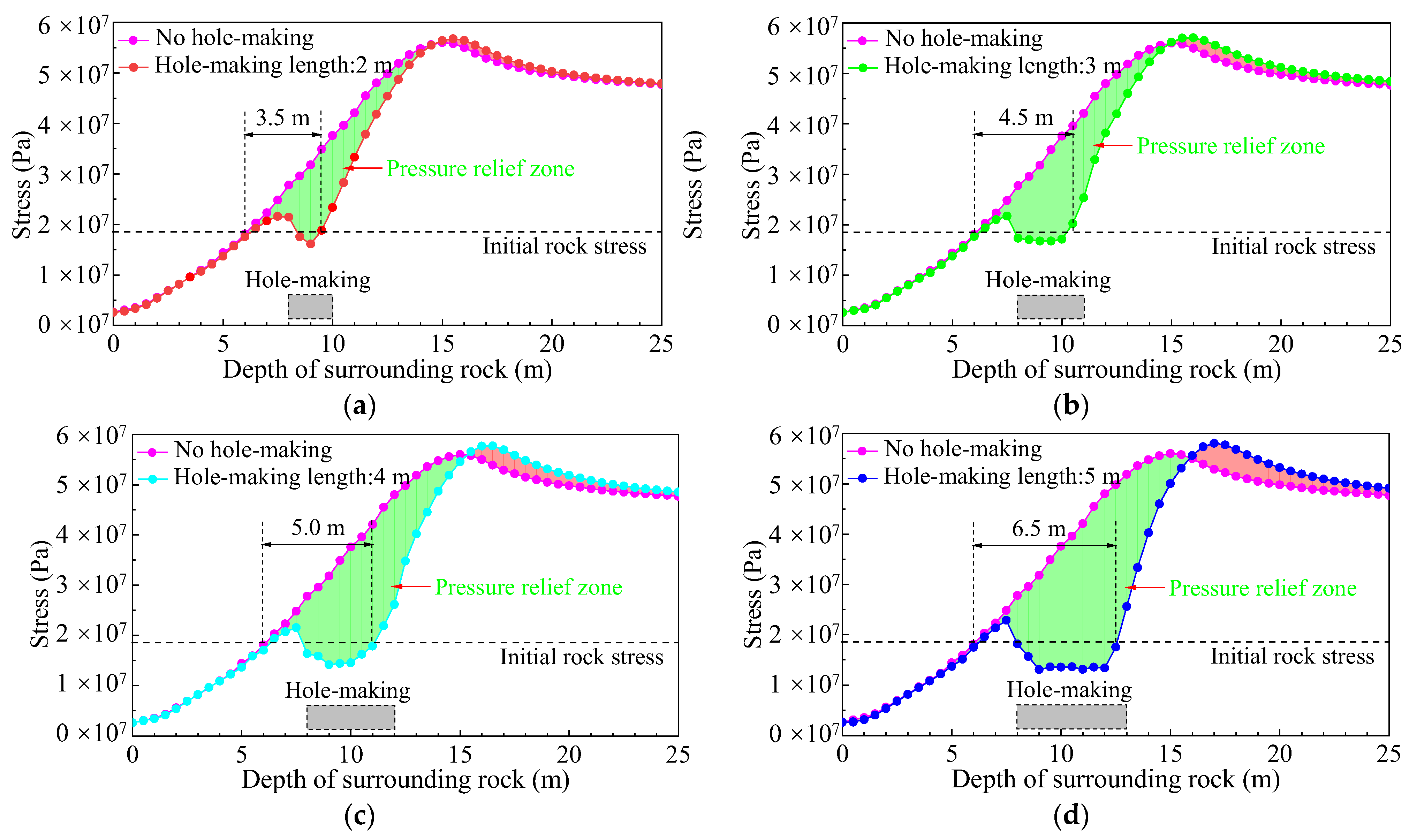
- Hole-making length
- (4)
- Determination of key technical parameters
5. Cooperative Control Technology of External Anchor–Internal Unloading of Surrounding Rock in Deep Coal Roadways
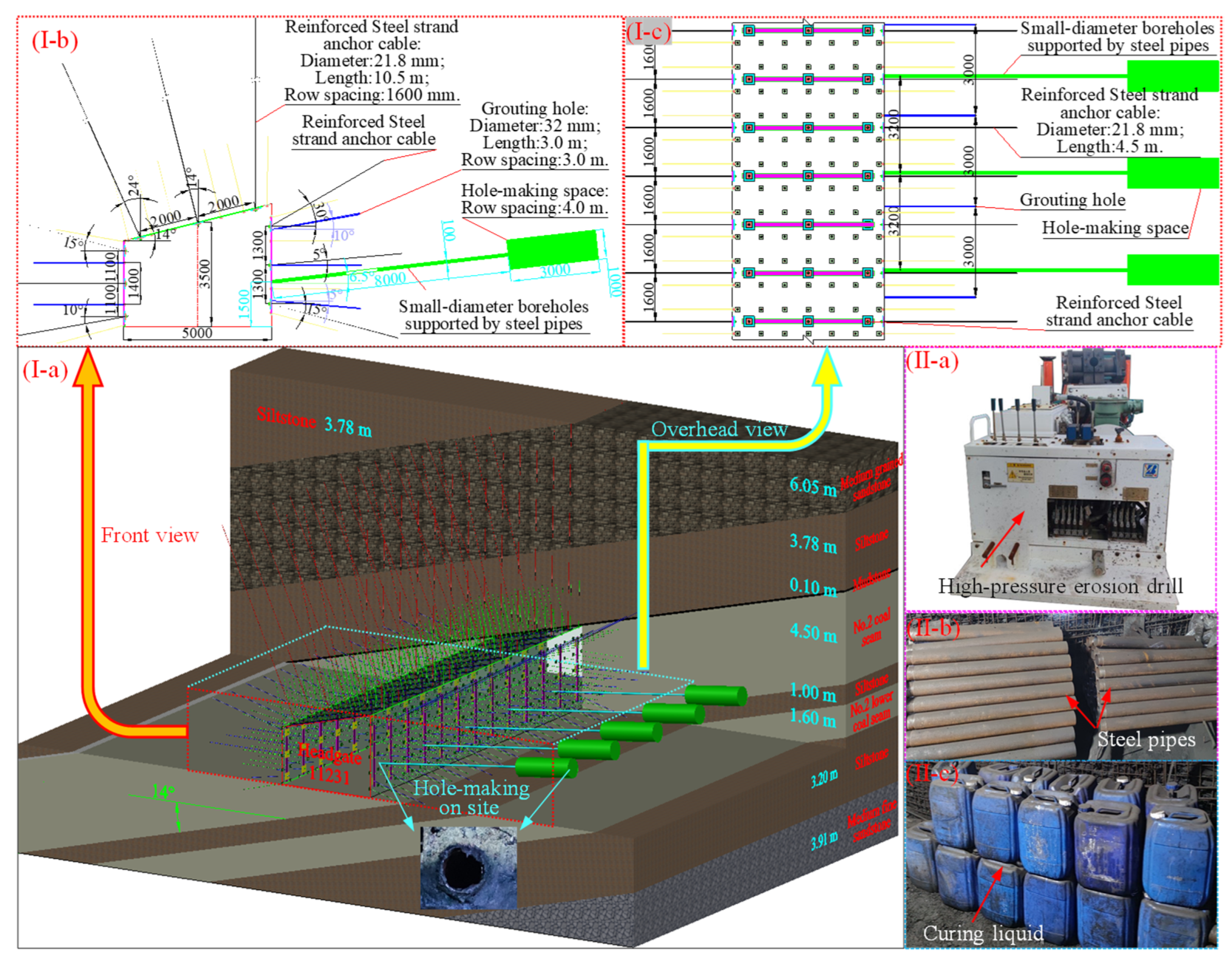
5.1. Technical Parameters of External Anchor–Internal Unloading of Surrounding Rock in the Test Section of Headgate 11231
5.2. Analysis on the Effect of Cooperative Control Technology of External Anchor–Internal Unloading in Roadway Surrounding Rock
- (1)
- Analysis of the prestressed field of the surrounding rock reinforced anchor cables in the coal roadway test section
- (2)
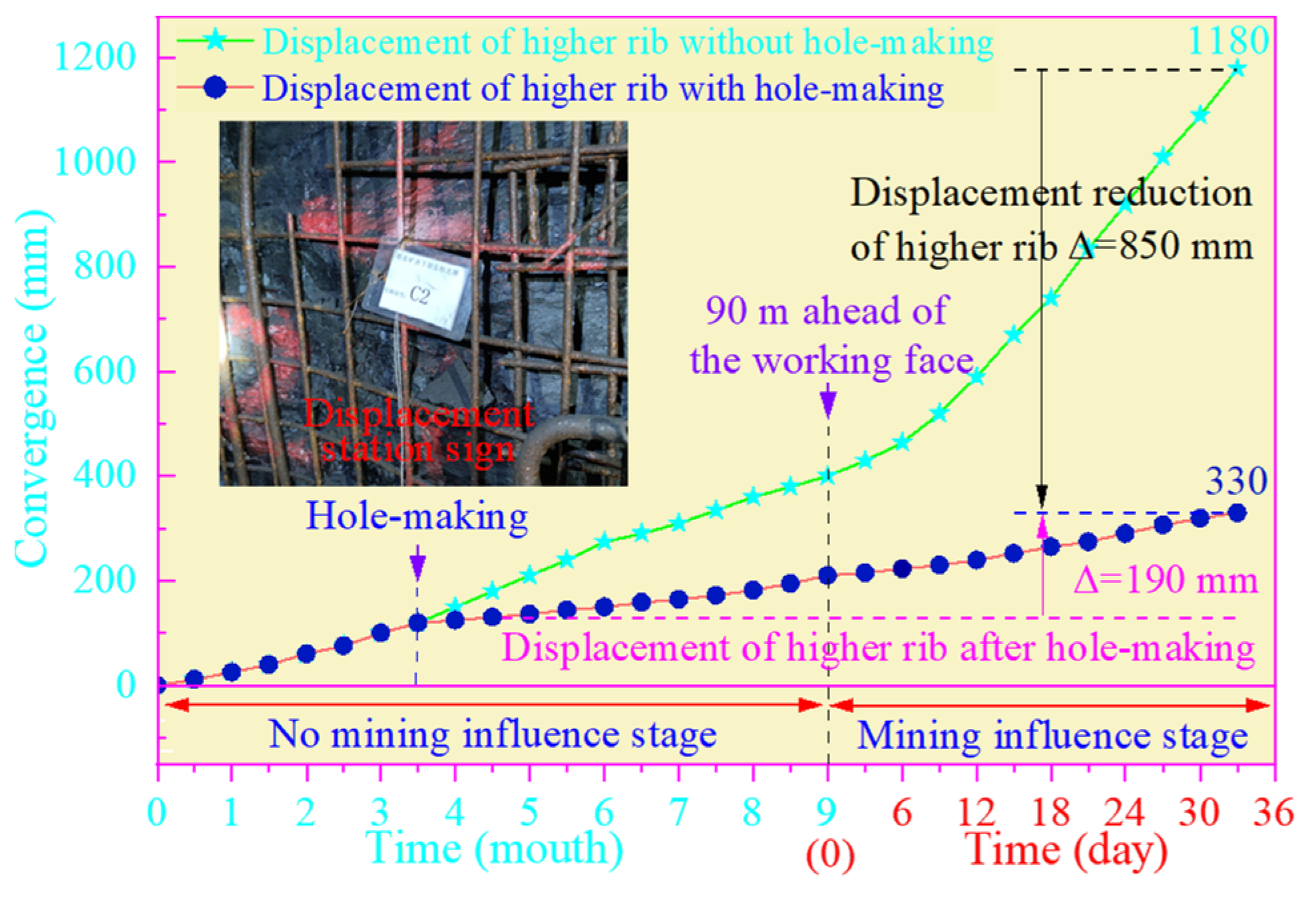
- Observation results and analysis of roadway surrounding rock displacement
6. Conclusions
- (1)
- Given the surrounding rock control problem of a large deformation mining roadway disturbed by deep dynamic pressure in a coal mine, the cooperative control technology of external anchor–internal unloading of surrounding rock of a large deformation coal roadway was proposed.
- (2)
- A numerical model conforming to the production of the geological conditions of panel 11231 of the coal mine was constructed, and the vertical stress distribution and transfer rule of surrounding rock under the conditions of five schemes for three key hole-making parameters were studied. The pressure relief degree and effect of each scheme’s hole-making space in the no dynamic pressure influence stage were analyzed using a variety of evaluation indices, and the reasonable parameter range of the surrounding rock hole-making space in this stage was obtained.
- (3)
- The pressure relief effect of each optimized scheme under the mining dynamic pressure condition of panel 11231 was studied, and the effective pressure relief range of each scheme was compared and a comprehensive evaluation of factors, such as construction benefit, cost, and construction period, was performed. Based on the results, the major technical parameters for pressure relief during hole-making were finally determined as follows: the hole-making depth, spacing, and length were 8 m, 3.2 m, and 3 m, respectively.
- (4)
- The field practice was carried out in the test section of headgate 11231. The monitoring results showed that the displacement of the hole-making rib was reduced by 850 mm, making the available width of the roadway no less than 4.2 m, which meets the ventilation and transportation requirements of the roadway, and eliminates roadway rib renovation, which ensures the stability of the surrounding rock. Thus, the new technology is of great significance for the further development of strategies for controlling the surrounding rock of deep coal roadways affected by dynamic pressure.
Author Contributions
Funding
Conflicts of Interest
References
- Jia, Z.; Xie, H.; Zhang, R.; Li, C.; Wang, M.; Gao, M.; Zhang, Z.; Zhang, Z. Acoustic Emission Characteristics and Damage Evolution of Coal at Different Depths Under Triaxial Compression. Rock Mech. Rock Eng. 2020, 53, 2063–2076. [Google Scholar] [CrossRef]
- Xie, H.; Li, C.; He, Z.; Li, C.; Lu, Y.; Zhang, R.; Gao, M.; Gao, F. Experimental study on rock mechanical behavior retaining the in situ geological conditions at different depths. Int. J. Rock Mech. Min. Sci. 2021, 138, 104548. [Google Scholar] [CrossRef]
- Xie, S.; Wu, Y.; Guo, F.; Zou, H.; Chen, D.; Zhang, X.; Ma, X.; Liu, R.; Wu, C. Application of Pre-Splitting and Roof-Cutting Control Technology in Coal Mining: A Review of Technology. Energies 2022, 15, 6489. [Google Scholar] [CrossRef]
- Huang, B.; Zhang, N.; Hong, J.; Kan, J.; Meng, B.; Li, N.; Xie, W.; Jiao, J. Large deformation theory of rheology and structural instability of the surrounding rock in deep mining roadway. J. China Coal Soc. 2020, 45, 911–926. [Google Scholar]
- Zhao, Y.; Zhou, J.; Liu, W. Characteristics of ground pressure and mechanism of coal burst in the gob side roadway at Xinjie deep mining area. J. China Coal Soc. 2020, 45, 1595–1606. [Google Scholar]
- He, M. Research progress of deep shaft construction mechanics. J. China Coal Soc. 2021, 46, 726–746. [Google Scholar]
- Xie, H.; Liu, T.; Gao, M.; Chen, L.; Zhou, H.; Ju, Y.; Gao, F.; Peng, X.; Li, X.; Peng, R.; et al. Research on in-situ condition preserved coring and testing systems. J. China Coal Soc. 2021, 18, 1840–1859. [Google Scholar] [CrossRef]
- Hou, C. Key technologies for surrounding rock control in deep roadway. J. China Univ. Min. Technol. 2017, 46, 970–978. [Google Scholar]
- Kang, H. Sixty years development and prospects of rock bolting technology for underground coal mine roadways in China. J. China Univ. Min. Technol. 2016, 45, 1071–1081. [Google Scholar]
- Xie, S.; Wu, Y.; Chen, D.; Liu, R.; Han, X.; Ye, Q. Failure analysis and control technology of intersections of large-scale variable cross-section roadways in deep soft rock. Int. J. Coal Sci. Technol. 2022, 9, 19. [Google Scholar] [CrossRef]
- Wu, C.; Qin, T.; Wang, L.; Liu, Z. Research on Surrounding Rock Control Technology of Dongbaowei Deep Mining Roadway. Adv. Civ. Eng. 2021, 2021, 6660989. [Google Scholar] [CrossRef]
- Wang, S.; Ju, W.; Pan, J.; Lu, C. Mechanism of energy partition evolution of excavation roadway rockburst in coal seam under tectonic stress field. J. China Coal Soc. 2019, 44, 2000–2010. [Google Scholar]
- Jing, H.; Wu, J.; Yin, Q.; Shi, X.; Zhao, Z. Particle flow simulation of rock burst and roof fall of deep coal roadway under dynamic disturbance. Chin. J. Rock Mech. Eng. 2020, 39, 3475–3487. [Google Scholar]
- Li, Q.; Hou, J.; Han, T.; Liu, H.; Wang, S. Failure characteristics and support techniques of surrounding rock for deep rectangular roadway in Yangzhuang mine. J. China Univ. Min. Technol. 2016, 45, 1124–1131. [Google Scholar]
- Jiang, Y.; Xu, Z.; Liu, Q.; Ma, H. An improved numerical manifold method for investigation of fracturing expan-sion and squeezing deformation of surrounding rock mass in deep coal roadway. J. China Coal Soc. 2020, 45, 579–589. [Google Scholar]
- Adigamov, A.E.; Yudenkov, A.V. Stress-strain behavior model of disturbed rock mass with regard to anisotropy and discontinuities. Min. Inf. Anal. Bull. 2021, 8, 93–103. [Google Scholar] [CrossRef]
- Khayrutdinov, A.M.; Kongar-Syuryun, C.B.; Kowalik, T.; Tyulyaeva, Y.S. Stress-strain behavior control in rock mass using different-stregth backfill. Min. Inf. Anal. Bull. 2020, 2020, 42–55. [Google Scholar] [CrossRef]
- Rybak, J.; Khayrutdinov, M.M.; Kuziev, D.A.; Kongar-Syuryun, C.B.; Babyr, N.V. Prediction of the geomechanical state of the rock mass when mining salt deposits with stowing. J. Min. Inst. 2022, 253, 61–70. [Google Scholar] [CrossRef]
- Kongar-Syuryun, C.B.; Ubysz, A.; Faradzhov, V. Models and algorithms of choice of development technology of deposits when selecting the composition of the backfilling mixture. IOP Conf. Ser. Earth Environ. Sci. 2021, 684, 012008. [Google Scholar] [CrossRef]
- Wu, Y.; Xie, S.; Zhang, Y. Research on stability control of roadway intersections with nested variable cross-section in deep mine. J. Min. Sci. Technol. 2022, 7, 720–729. [Google Scholar]
- Zhang, N.; Wang, C.; Gao, M.; Zhao, Y. Roadway support difficulty classification and controlling techniques for Huainan deep coal mining. Chin. J. Rock Mech. Eng. 2009, 28, 2421–2428. [Google Scholar]
- Ma, N.; Zhao, Z.; Feng, J. Technology of butt long bolt on roadway supporting in difficult conditions. Coal Sci. Technol. 2013, 41, 117–121. [Google Scholar]
- Xie, S.; Wu, Y.; Ma, X.; Chen, D.; Guo, F.; Jiang, Z.; Li, H.; Zou, H.; Liu, R.; Zhang, X. Reasonable stopping method and retracement channel support at fully mechanized top coal caving working face of 15 m extra-thick coal seam: A case study. Energy Sci. Eng. 2022, 1–22. [Google Scholar] [CrossRef]
- Li, S.; Wang, Q.; Li, W.; Wang, D.; Li, Z.; Jiang, B.; Wang, H.; Wang, H. Comparative field test study of pressure relief anchor box beam support system in deep thick top coal roadway. Chin. J. Rock Mech. Eng. 2012, 31, 656–666. [Google Scholar]
- He, F.; Gao, F.; Sun, Y.; Li, S.; Song, B.; Yang, Y. Multiple-cable-girder-truss asymmetric support mechanism and its application in the roadway of fully mechanized top coal caving face with narrow coal pillar. J. China Coal Soc. 2015, 40, 2296–2302. [Google Scholar]
- Yu, H.; Jia, H.; Liu, S.; Liu, Z.; Li, B. Macro and micro grouting process and the influence mechanism of cracks in soft coal seam. Int. J. Coal Sci. Technol. 2021, 8, 969–982. [Google Scholar] [CrossRef]
- Huang, W.; Gao, Y.; Wen, Z.; Gao, L. Technology of gob-side entry retaining using concrete-filled steel tubular column as roadside supporting. J. China Univ. Min. Technol. 2015, 44, 604–611. [Google Scholar]
- Xie, S.; Pan, H.; Zeng, J.; Wang, E.; Qiao, S. A case study on control technology of surrounding rock of a large section chamber under a 1200-m deep goaf in Xingdong coal mine, China. Eng. Fail. Anal. 2019, 104, 112–125. [Google Scholar] [CrossRef]
- Zhang, S.; Chen, L.; Jia, H. The surrounding rock of deep borehole pressure relief and let the pressure bolt coupling analysis. Appl. Mech. Mater. 2014, 446–447, 1421–1424. [Google Scholar]
- Luo, Y.; Xu, K.; Huang, J.; Li, X.; Liu, T.; Qu, D.; Chen, P. Impact analysis of pressure-relief blasting on roadway stability in a deep mining area under high stress. Tunn. Undergr. Space Technol. 2021, 110, 103781. [Google Scholar] [CrossRef]
- Cheng, S.; Ma, Z.; Gong, P.; Li, K.; Li, N.; Wang, T. Controlling the deformation of a small coal pillar retaining roadway by non-penetrating directional pre-splitting blasting with a deep hole: A case study in Wangzhuang coal mine. Energies 2020, 13, 3084. [Google Scholar] [CrossRef]
- Chen, J.; Yang, C.; Zhu, Y.; He, F. Distressing maintenance analysis on roadway of large deformation in soft rocks with pillarless fully-mechanized sublevel caving system and its application. Chin. J. Rock Mech. Eng. 2002, 21, 5. [Google Scholar]
- Zhang, X.; Pak, R.Y.; Gao, Y.; Liu, C.; Zhang, C.; Yang, J.; He, M. Field experiment on directional roof presplitting for pressure relief of retained roadways. Int. J. Rock Mech. Min. Sci. 2020, 134, 104436. [Google Scholar] [CrossRef]
- Yin, D.; Chen, S.; Liu, S.; Ma, H. Effect of joint angle in coal on failure mechanical behavior of roof rock-coal combined body. Q. J. Eng. Geol. Hydrogeol. 2018, 51, 202–209. [Google Scholar] [CrossRef]
- Chen, Y.; Zuo, J.; Liu, D.; Li, Y.; Wang, Z. Experimental and numerical study of coal-rock bimaterial composite bodies under triaxial compression. Int. J. Coal Sci. Technol. 2021, 8, 908–924. [Google Scholar] [CrossRef]
- Wang, W.; Wang, G.; Zhao, W.; Wang, L.; Feng, Z.; Cui, R.; Du, F. Numerical assessment of the pressure relief effect of the hydraulic punching cavitation technique in a soft coal seam. Geomech. Geophys. Geo-Energy Geo-Resour. 2022, 8, 30. [Google Scholar] [CrossRef]


| Rock Strata | /GPa | /GPa | /MPa | /MPa | /(°) | /(kg·m−3) |
|---|---|---|---|---|---|---|
| No. 1 coal seam | 2.60 | 1.60 | 1.00 | 1.32 | 25.0 | 1.40 |
| Siltstone | 4.77 | 4.59 | 3.60 | 3.15 | 32.5 | 2.65 |
| Sandy mudstone | 4.87 | 4.18 | 3.20 | 3.10 | 35.0 | 2.40 |
| Medium grained sandstone | 4.50 | 4.10 | 3.15 | 3.05 | 33.0 | 2.65 |
| No. 2 coal seam | 2.60 | 1.60 | 1.00 | 1.32 | 25.0 | 1.40 |
| Mudstone | 4.20 | 4.10 | 2.00 | 2.00 | 28.0 | 2.40 |
| No. 2 lower coal seam | 2.60 | 1.60 | 1.00 | 1.32 | 25.0 | 1.40 |
| Medium fine sandstone | 4.77 | 4.88 | 4.10 | 3.80 | 33.0 | 2.65 |
| Overlying strata | 4.87 | 4.18 | 3.20 | 3.10 | 35.0 | 2.40 |
| Lower strata | 4.77 | 4.59 | 3.60 | 3.15 | 32.5 | 2.65 |
| Scheme Number | Technical Parameter of Hole-Making | ||||||
|---|---|---|---|---|---|---|---|
| Schemes 1–5 | L2/m | L3/m | L1/m | ||||
| 4.0 | 3.0 | 4.0 | 6.0 | 8.0 | 10.0 | 12.0 | |
| Schemes 6–10 | L1/m | L3/m | L2/m | ||||
| 8.0 | 3.0 | 2.4 | 3.2 | 4.0 | 4.8 | 5.6 | |
| Schemes 11–15 | L1/m | L2/m | L3/m | ||||
| 8.0 | 4.0 | 1.0 | 2.0 | 3.0 | 4.0 | 5.0 | |
| Evaluation Index | Scheme Number (Hole-making depth) | |||||
| Scheme 1 | Scheme 2 | Scheme 3 | Scheme 4 | Scheme 5 | ||
| 1 | Pressure relief effect | No | Good | Excellent | No | Poor |
| 2 | Transfer distance to deep/m | 0.5 | 1.5 | 3.0 | −1.0 | 1.0 |
| Evaluation index | Scheme number (Hole-making spacing) | |||||
| Scheme 6 | Scheme 7 | Scheme 8 | Scheme 9 | Scheme 10 | ||
| 1 | Pressure relief effect | Excellent | Good | Fair+ | Fair | Fair |
| 2 | Transfer distance to deep/m | 3.0 | 2.5 | 2.0 | 2.0 | 1.0 |
| Evaluation index | Scheme number (Hole-making length) | |||||
| Scheme 11 | Scheme 12 | Scheme 13 | Scheme 14 | Scheme 15 | ||
| 1 | Pressure relief effect | Fair | Good | Good | Good | Good |
| 2 | Transfer distance to deep/m | 1.5 | 2.0 | 3.0 | 3.5 | 5.0 |
| 3 | k | 1.90 | 0.90 | 0.56 | 0.51 | 0.54 |
| 4 | K | 1.5 | 1.0 | 1.0 | 0.875 | 1.0 |
Publisher’s Note: MDPI stays neutral with regard to jurisdictional claims in published maps and institutional affiliations. |
© 2022 by the authors. Licensee MDPI, Basel, Switzerland. This article is an open access article distributed under the terms and conditions of the Creative Commons Attribution (CC BY) license (https://creativecommons.org/licenses/by/4.0/).
Share and Cite
Xie, S.; Li, H.; Chen, D.; Feng, S.; Ma, X.; Jiang, Z.; Cui, J. New Technology of Pressure Relief Control in Soft Coal Roadways with Deep, Violent Mining and Large Deformation: A Key Study. Energies 2022, 15, 9208. https://doi.org/10.3390/en15239208
Xie S, Li H, Chen D, Feng S, Ma X, Jiang Z, Cui J. New Technology of Pressure Relief Control in Soft Coal Roadways with Deep, Violent Mining and Large Deformation: A Key Study. Energies. 2022; 15(23):9208. https://doi.org/10.3390/en15239208
Chicago/Turabian StyleXie, Shengrong, Hui Li, Dongdong Chen, Shaohua Feng, Xiang Ma, Zaisheng Jiang, and Junqi Cui. 2022. "New Technology of Pressure Relief Control in Soft Coal Roadways with Deep, Violent Mining and Large Deformation: A Key Study" Energies 15, no. 23: 9208. https://doi.org/10.3390/en15239208
APA StyleXie, S., Li, H., Chen, D., Feng, S., Ma, X., Jiang, Z., & Cui, J. (2022). New Technology of Pressure Relief Control in Soft Coal Roadways with Deep, Violent Mining and Large Deformation: A Key Study. Energies, 15(23), 9208. https://doi.org/10.3390/en15239208