Article

Comparative Performance of DFIG and PMSG Wind Turbines during Transient State in Weak and Strong Grid Conditions Considering Series Dynamic Braking Resistor

1
Department of Electrical and Communication Engineering, National University of Science and Technology, Al Hail, Muscat PC 111, Oman
2
Department of Electrical and Electronic Engineering, Nisantasi University, Istanbul 25370, Turkey
3
Department of Electrical and Electronic Engineering, Qatar University, Doha 2713, Qatar
*
Author to whom correspondence should be addressed.
Energies 2022, 15(23), 9228; https://doi.org/10.3390/en15239228
Submission received: 2 November 2022 / Revised: 22 November 2022 / Accepted: 26 November 2022 / Published: 6 December 2022
(This article belongs to the Section A: Sustainable Energy)

Abstract

:
The recently stipulated grid codes require wind generators to re-initiate normal power production after grid voltage sag. This paper presents a comparative performance of two commonly employed variable speed wind turbines in today’s electricity market, the doubly fed induction generator (DFIG) and the permanent magnet synchronous generator (PMSG) wind turbines. The evaluation of both wind turbines was performed for weak, normal and strong grids, considering the same machine ratings of the wind turbines. Because of the critical situations of the wind turbines during faulty conditions in the weak grids, an analysis was done considering the use of effective series dynamic braking resistor (SDBR) for both wind turbines. The grid voltage variable was employed as the signal for switching the SDBR in both wind turbines during transient state. Additionally, an overvoltage protection system was considered for both wind turbines using the DC chopper in the DC-link excitation circuitry of both wind turbines. Furthermore, a combination of the SDBR over-voltage protection scheme (OVPS) was employed in both wind turbines at weak grid condition in order to improve the performance of the variable speed wind turbines and keep the operation of the power converters within their permissible limits. Furthermore, the performance of the DFIG and PMSG wind turbines in weak grids were further investigated, considering the combination of 75% and 50% effectively sized SDBR and OVPS. It was observed that, even with a 50% reduction in SDBR or OVPS, the performance of both wind turbines is still satisfactory with faulty conditions. Therefore, it is recommended to use a combination of the SDBR and OVPS with DFIG- or PMSG-based variable speed wind turbines to achieve a superior fault ride through performance, especially in weak grids. The system performance was evaluated using the power system computer design and electromagnetic transient including DC (PSCAD/EMTDC) platform.

1. Introduction

For wind farms that are grid-tied to be effectively operated, the wind generators response is vital in order to propose new approaches of power grid stabilization [1,2]. With the recent grid requirements, wind farms should perform well under grid fault, based on voltage and robust frequency controls. The two basic variable speed wind turbines employed in wind energy conversion are the doubly fed induction generator (DFIG) and the permanent magnet synchronous generator (PMSG). The huge advancement from the earlier fixed speed wind turbine to variable speed wind turbines in the extraction and improvement in wind energy technology is due to modern power electronics and control methods developed over the years [3,4]. Although the earlier fixed speed wind turbine generators may have some benefits, such as being simple in operation, having rugged construction, being cheaper to purchase and having a low maintenance cost, their technology has a drawback of large reactive power requirement during the transient state to help boost the recovery of their air gap flux. In addition, they lack control of voltage and frequency, consequently requiring external expensive reactive power devices. As a result of these shortcomings, this type of wind turbine is not commonly employed in wind energy conversion.
In light of the above, the new norm for wind farm installations is variable speed wind turbines. This is because their efficiency to capture energy is very high, control of voltage is possible and the stresses in the drive train are reduced [5]. The DFIG and PMSG with power converters that are back-to-back connected are now the modern two wind generator technologies. The former has a gearbox, and a rating generator capacity of 20–30% is required for its speed of operation range of 0.7–1.3 per unit (p.u). The expensive power converters of the latter are a setback because they are full rated.
DFIG wind turbine power converter is designed in such a way that it is between the rotor and the stator sides of the machine. Depending on the wind speeds, this type of wind generator can be operated within a wider range for the effective capture of wind energy [6,7]. Additionally, it is easier to rebuild the terminal voltage after the transient state because of the pitch and dynamic slip control [8,9]. Furthermore, this type of wind turbine can easily regulate both active and reactive power via decoupling principles. The insulated gate bipolar transistors (IGBTs) of the DFIG power converters usually switches off and goes into standby mode at lower voltages [10,11,12,13]. However, for certain voltages above the threshold value, during the transient state, the turbine is synchronized quickly to the power grid.
The PMSG wind turbine technology is having a back-to-back power converter that is fully rated, linking the grid. As a result, compared to the DFIG topology, the flexibility of this wind generator is better, due to real and reactive power effective control. Though, a major setback for this wind generator is its high cost.
Much research exists in the literature on the fault ride through strategies, regarding DFIG and PMSG wind turbines. These include the use of a fault current limiter at different positions of the DFIG structure [14,15,16,17], the use of external reactive power compensation devices, crowbar switch and DC chopper circuitry [18,19]. References [20,21] proposed sliding mode controls for DFIG with maximum power point tracking (MPPT), considering the active and reactive powers. In [22,23,24], the authors did the fault ride through assessment of a DFIG using various control topologies, while an MPPT pitch angle considering algorithms of converting wind energy was reported in [25]. In References [26,27], the PMSG wind turbine, was analysed based on peak current limitation and MPPT for both power converters of the wind turbine. A costly crowbar switch was employed to maintain the voltage of the DC-link close to the tolerable range during the transient state. In [28], the improvement of PMSG fault ride through was made using a superconducting fault current limiter (SFCL).
Power grids could be classified based on their short circuit ratio (SCR). A weak grid has low SCR, with high impedance and low inertia constant, while a strong grid has high SCR, with low impedance and high inertia constant. In the literature, several works on weak grids and the challenges they pose to network stability considering wind energy penetration has been reported [29,30,31]. The interface of a voltage source converter (VSC) with pulse width modulation (PWM) scheme has great influence on the power grid stability [30,31]. Reference [32] showed that the controllers of wind turbines could be improved in weak grids during voltage variations.
In this paper, a comparative analysis regarding stability issues faced by DFIG and PMSG wind turbines are investigated in various grid strengths. The modelling and wind turbine characteristics of both wind generators were analysed along with their control strategies. Both wind turbines were subjected to weak, normal, and strong grids with three line-to-ground faults (3LG) severely bolted, without any protection or enhancement scheme, in order to test the robustness of the controllers employed. The mathematical dynamics of the implementation of the series dynamics braking resistor (SDBR) as a limiter of the fault current at the stator of both wind turbines for effective comparison study was also presented. The effective SDBR size was used for both wind turbine technologies, considering the same switching signal of the grid voltage during the transient state. Furthermore, an over voltage protection system was considered for both wind turbines based on the connection of a DC chopper circuitry at the power converter of the wind turbines. The salient part of this study is the combination of the SDBR and over-voltage protection scheme (OVPS) of the DC chopper for both wind turbines operating at weak grids, which is characterized by the ratio of reactive and ohmic ( X / R ) values of the impedance ( Z ) . The evaluation of both wind turbines was done for weak, normal and strong grids, considering the same machine ratings of the wind turbines. Because of the critical situations of the wind turbines during faulty conditions in the weak grids, an analysis was done considering the use of effective SDBR for both wind turbines. The grid voltage variable was employed as a signal for switching the SDBR in both wind turbines during the transient state. Additionally, an overvoltage protection system was considered for both wind turbines using the DC chopper in the DC-link excitation circuitry of both wind turbines. Furthermore, a combination of the SDBR and DC chopper was employed in both wind turbines at weak grid conditions in order to improve the performance of the variable speed wind turbines. The hybrid scheme of the SDBR and OVPS in both wind turbines was able to improve the performance of the variables of the wind turbine and keep the operation of the power converters within their permissible limits. Investigation of 75% and 50% reduction in the hybrid SDBR and OVPS was also performed for both wind turbines in weak grid scenario during the transient state. A 50% reduction in SDBR or OVPS, would still help in keeping the performances at a satisfactory level. Consequently, the use of SDBR and OVPS hybrid approach in DFIG- or PMSG-based variable speed wind turbine would help achieve a superior fault ride through performance in weak grids during faulty conditions. There is limited number of papers in the literature that consider the scenarios of weak and strong grids for both wind turbines, in conjunction with the SDBR control and OVPS topologies. Most papers in the literature considered these scenarios on a separate basis than the fault ride through enhancement of both wind generators.

2. Modelling and Control

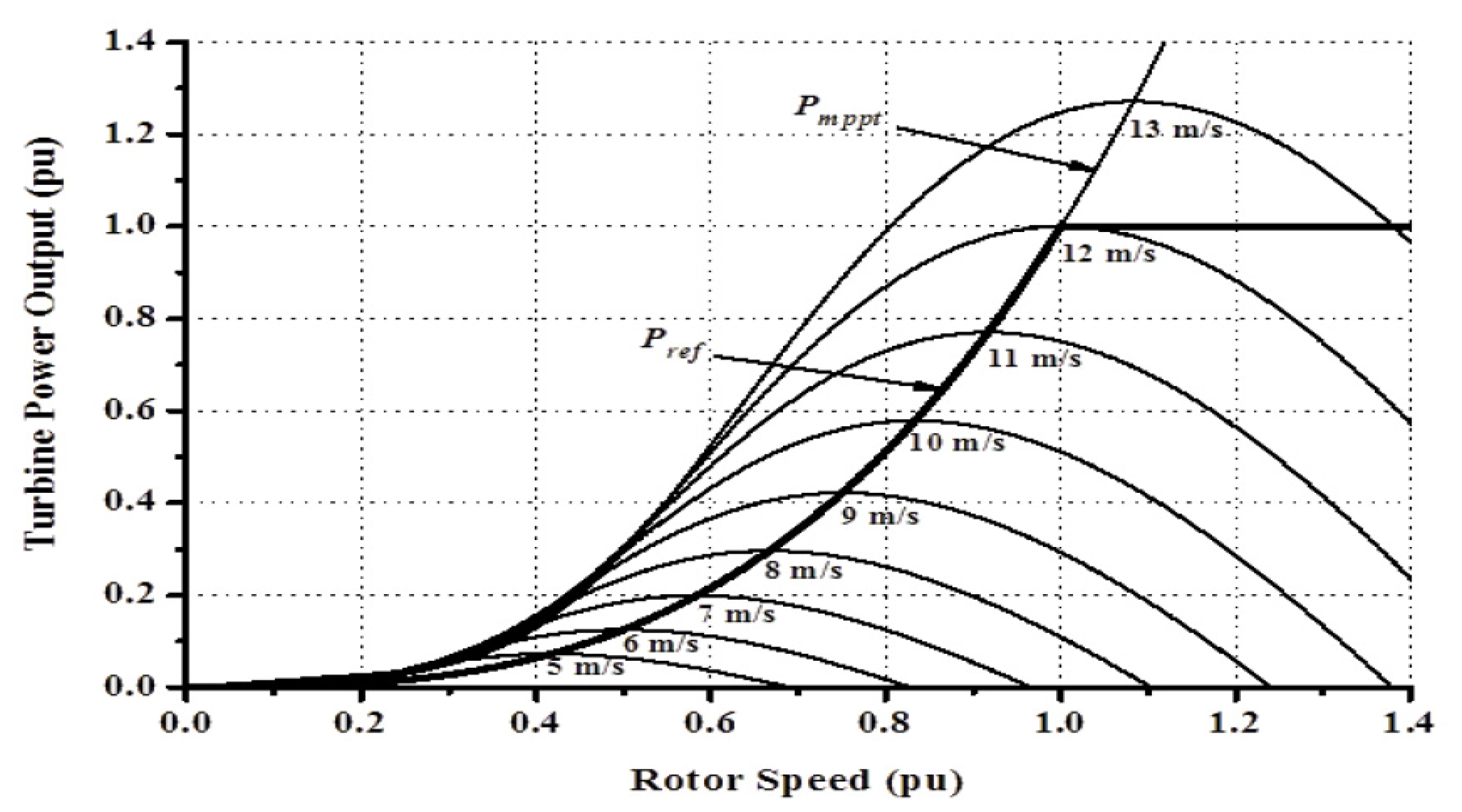
2.1. Wind Turbine Characteristics

Equations (1) and (2) give the DFIG torque and mechanical extracted power [32,33].
T m = π ρ R 3 2 V w 2 C t ( λ ) [ N m ]
P m = π ρ R 2 2 V w 3 C P ( λ ) [ W ]
where   ρ , air density; R, radius of the turbine; V w , wind speed; and C p ( λ , β ) , is the power coefficient given by:
C p ( λ , β ) = 0.5 ( Γ 0.02 β 2 5.6 ) e 0.17 Γ
C t and C P are related by:
C t ( λ ) = C p ( λ ) λ
λ = ω r R V w
Γ = R λ ( 3600 ) ( 1609 ) from Equation (3), and the ratio of the speed tip is λ .
Figure 1 shows the wind turbine characteristics for the DFIG, with speed range 0.7 pu to 1.3 pu and a maximum power of 0.97 pu. On the other hand, the PMSG maximum power is at a turbine speed of 1.0 pu, as shown in Section 2.3.

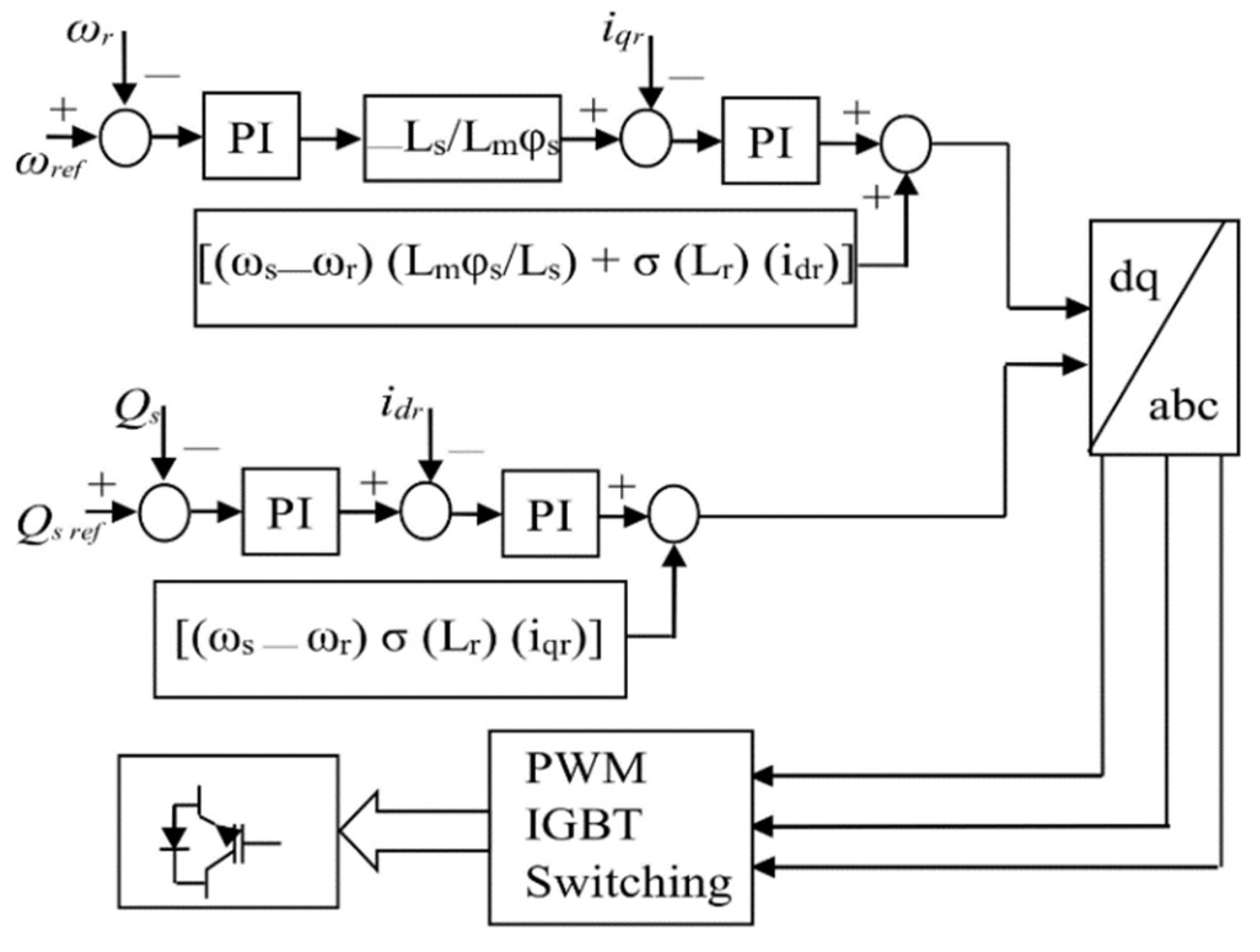
2.2. DFIG Model and Control

Details of the DFIG model and control can be obtained from [34,35,36,37]. The rotor side converter (RSC) regulates the axes q and d currents i q r and i d r in Figure 2. This is completed by ( P s , Q s ) of the stator. The P s is obtained by the MPPT. In Figure 3, the GSC regulates the voltage of the DC-link and reactive power exchange at the point of common coupling (PCC), considering the power flow in the rotor. Furthermore, the transformations of dq/abc and abc/dq, with regard to the ac voltage for effective synchronism, are achieved via the phase locked loop (PLL) scheme.

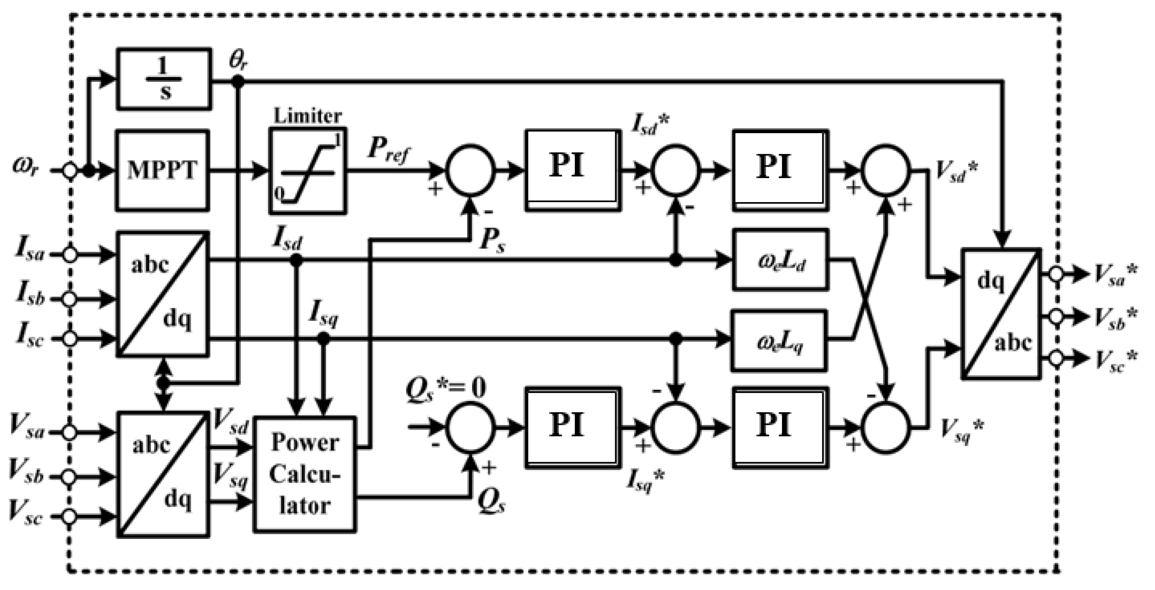
2.3. PMSG Model and Control

The PMSG reference power P r e f is based on its rated power. The grid-connected fully rated PMSG has back-to-back power converters [38], with typical turbine characteristics shown in Figure 4. In order to realize MPPT [39,40], the MSC controls the speed, while power quality and power factor regulation and DC voltage stabilization are completed by the GSC.
Details of the PMSG model and control can be obtained from [41,42,43,44]. Figure 5 shows the PMSG MSC control, where the active and reactive power regulation is done. The abc/dq transformation is obtained by the rotor (θr) angle taking the wind generator speed into consideration. The Isd, Isq regulates both (Ps) and (Qs) variables. The strategy of the MPPT is employed in the (Pref). Usually, (Qs*) is fixed at 0 to unity power factor. Vsa*, Vsb* and Vsc* are used for switching the PWM by the current controllers output, considering Vsd* and Vsq*. The control of the GSC in Figure 6 is based on d-q reference frame and the grid voltage. Iga, Igb and Igc and Vga, Vgb and Vgc are transformed into a reference d-q rotating frame by Park transformation. PLL is used for the phase angle (θg) extraction.

3. Mathematical Dynamics of SDBR in DFIG Wind Turbine

The DFIG stator voltage during the transient state [45] is:
v s s = V s + e j ω S t + V s e j ω S t
V s + ,   V s are components of the stator’s positive and negative voltage sequences. At normal state, the stator flux is:
      ψ s s s = v s + e j ω S t j ω s + v s e j ω S t j ω s
A grid voltage drop would result in stator flux transient components counteracting the state of the transition variables; thus, the natural flux ( ψ s n ) based on stator flux is [46]:
ψ s s = ψ s s s + ψ s n s = v s + e j ω S t j ω s + v s e j ω S t j ω s + ψ s n s e t τ S
With τ s = L s R s   as the stator flux time constant.
The first and second terms in Equation (8) are the forced flux and the natural flux ( ψ s n ). The stator flux is related to the rotor reference frame by:
ψ s r = ψ s s e j ω r t
Furthermore, the rotor induced voltage is:
v ¯ r o = L m L s d ψ s ¯ d t
The DFIG rotor open circuit voltage based on Equations (8) to (10) is [45,46]:
v ¯ r o = L m L s s V + e j s ω S t + L m L s ( s 2 ) V e j ( 2 s ) ω S t + L m L s ( j ω r + 1 τ s ) ψ s n e t τ s e j ω r t
Neglecting the 1 τ s term leads to in Equation (11), gives:
v ¯ r o = L m L s s V + e j s ω S t + L m L s ( s 2 ) V e j ( 2 s ) ω S t + L m L s A ( 1 s ) e t τ s e j ω r t
It can be concluded that the presence of the SDBR would increase the stator resistance as:
R s e f f e c t i v e = R s + R s d b r
Consequently, during the transient state, τ s e f f e c t i v e = L s R s e f f e c t i v e is the effective time constant that would help reduce the total current in order to achieve reduced oscillations.

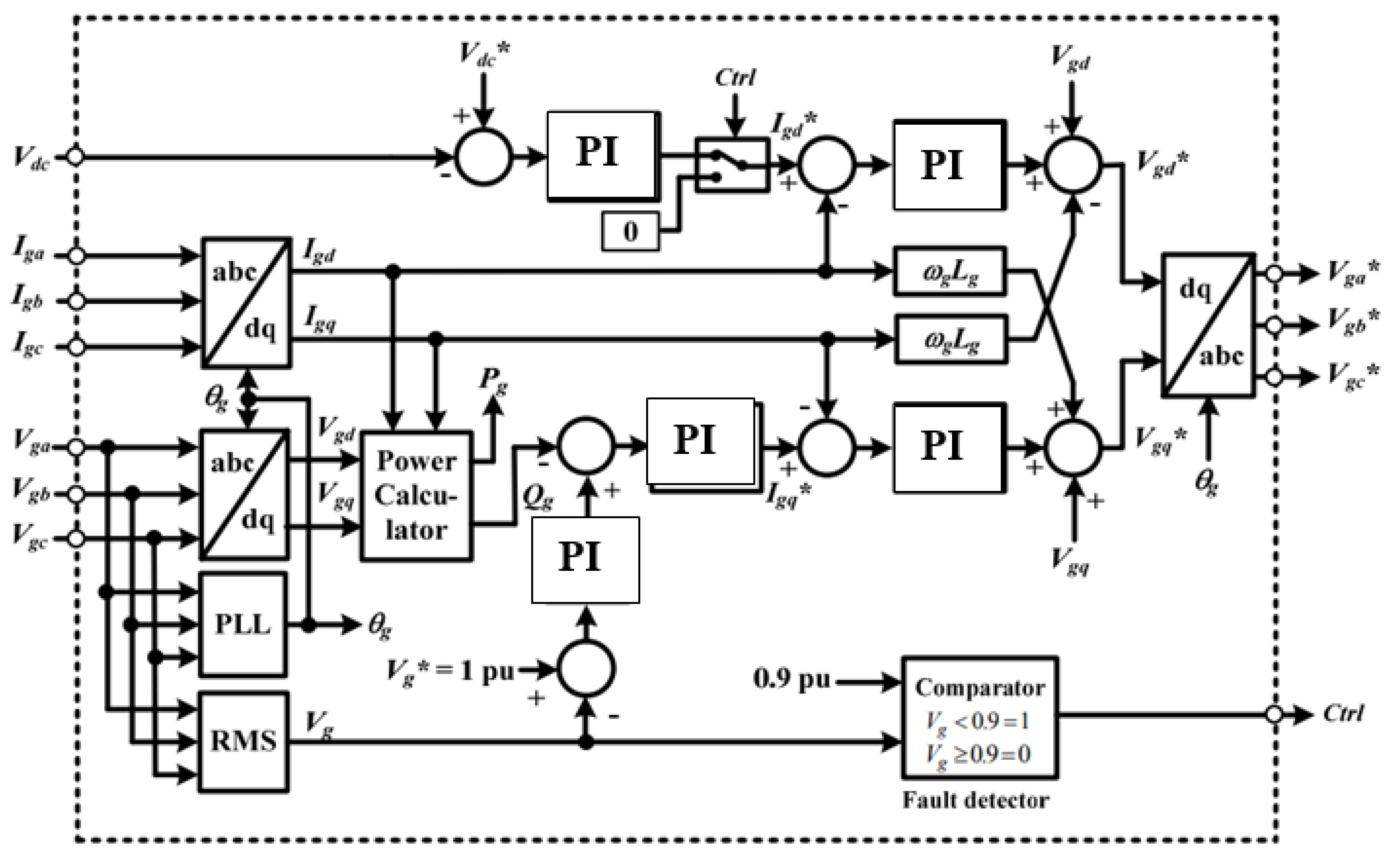
4. SDBR and PMSG Mathematical Dynamics

The three-phase mathematical model of the converter in Figure 4 is [47]:
e d = ω L i q + L d i d d t + ( R + R S D B R ) i d + 0.5 U d c β d
e q = ω L i d + L d i q d t + ( R + R S D B R ) i q + 0.5 U d c β q
C d U d c d t = 0.75 ( i d β d + i q β q ) U d c R L
r = β d 2 + β q 2
The voltages of the dq components are:
  e d = E m
    e q = 0
From Equation (18),
P s = 3 2 E m i d
                          Q s = 3 2 E m i q
For power factor of 1, i q _ r e f is 0, and i q = i q r e f = 0 for current regulation. With i q = 0 and e q = 0 ,
E m = L d i d d t + ( R + R S D B R ) i d + 0.5 U d c β d
  β q = 2 ω L U d c i q
C d U d c d t = 3 4 i d β d U d c R L
Inserting SDBR would lead to:
E m = ( R + R S D B R ) i d + 0.5 U d c β d
      β q = 2 ω L U d c i q
  i d = 4 U d c 3 β d R L
Putting Equation (26) into (27) for a given load of R L , and voltage U d c , the expression of the signal command β d is [47]:
6 E m R L β d 8 ( R + R S D B R ) U d c 3 R L β d 2 U d c = 0
Equation (28) has two solutions:
β d 1 = E m U d c ( E m U d c ) 2 8 ( R + R S D B R ) 3 R L
β d 2 = E m U d c + ( E m U d c ) 2 8 ( R + R S D B R ) 3 R L
If β d = β d 2 , then:
( E m U d c ) 2 8 ( R + R S D B R ) 3 R L 0
Considering the load power, it is possible to operate the converter if:
P d c P d c _ m a x
Based on the principle of power conservation, P d c _ m a x is:
P d c = 3 2 E m i d 3 2 ( R + R S D B R ) i d 2
By solving d P d c / d i d = 0 , it leads to:
d P d c d i d = 3 2 E m 3 R i d = 0 i d = i d _ m a x = E m 2 R
Combining Equations (33) and (34):
  P d c _ m a x = 3 E m 2 8 ( R + R S D B R )
The operation of the power converter is possible if:
P d c P d c _ m a x ( E m U d c ) 2 8 ( R + R S D B R ) 3 R L 0
Equation (36) shows Equation (31) conditions. Finally, from Equations (21) and (35), P s _ m a x :
P s _ m a x = 3 E m 2 4 ( R + R S D B R )
From Equation (37), the PMSG GSC maximum power transfer reduced with SDBR insertion during grid fault, with low currents and oscillations.

5. Results and Discussions

Rigorous simulation studies are conducted to compare the fault ride through features in different grid conditions. The rating of the parameters of both wind turbines are given in Table 1. The system performance was evaluated using the PSCAD/EMTDC [48] environment. The fault types are symmetrical three-phase and an unsymmetrical single line-to-ground of 100 ms happening at 10.1 s, with the circuit breakers operation sequence opening and reclosing at 10.2 s and 11 s, respectively, on the faulted line at the terminals of both wind turbines. The fault performance with and without stability augmentation tools, such as the SDBR and over-voltage protection system (OVPS), are presented below in detail.

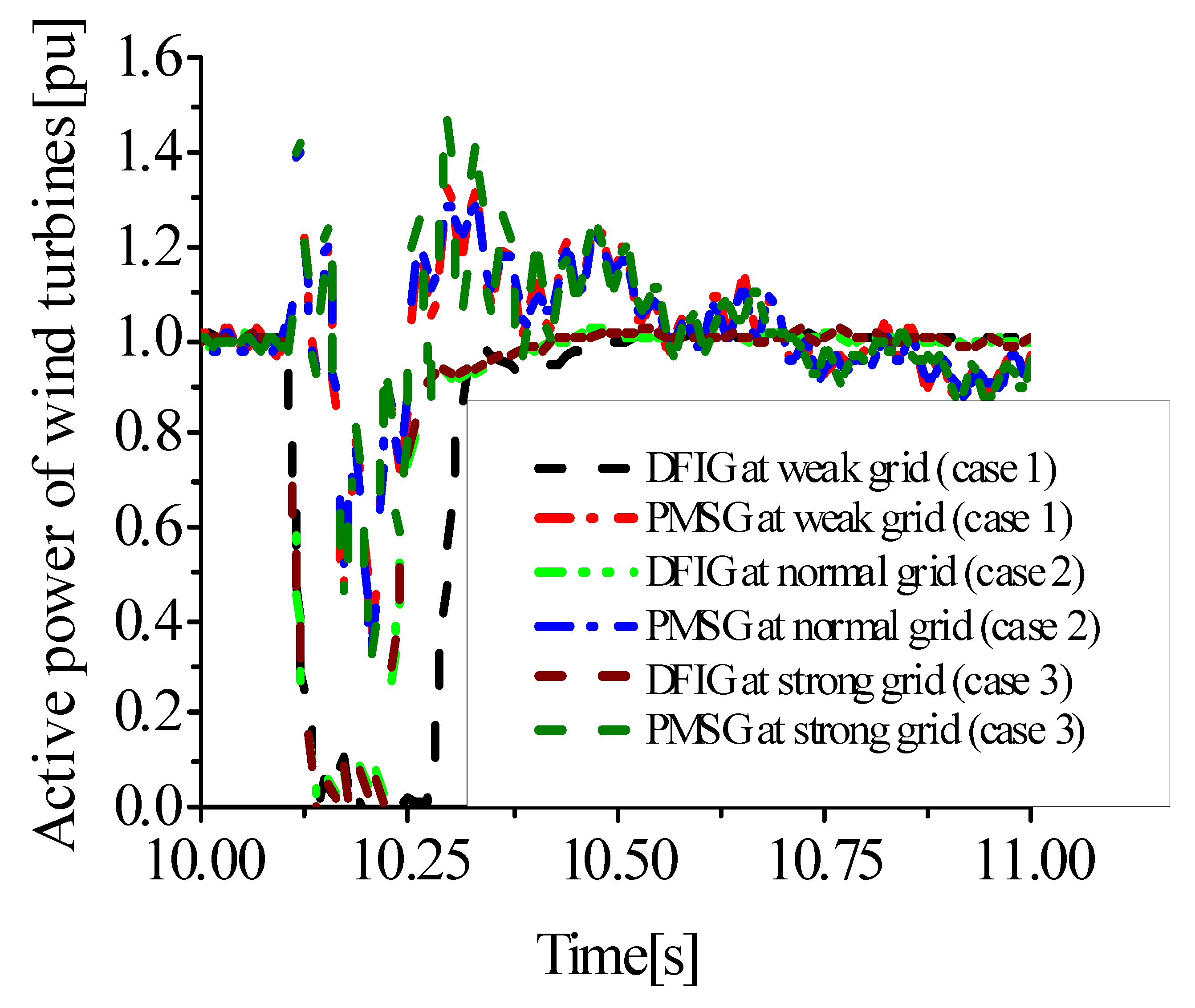
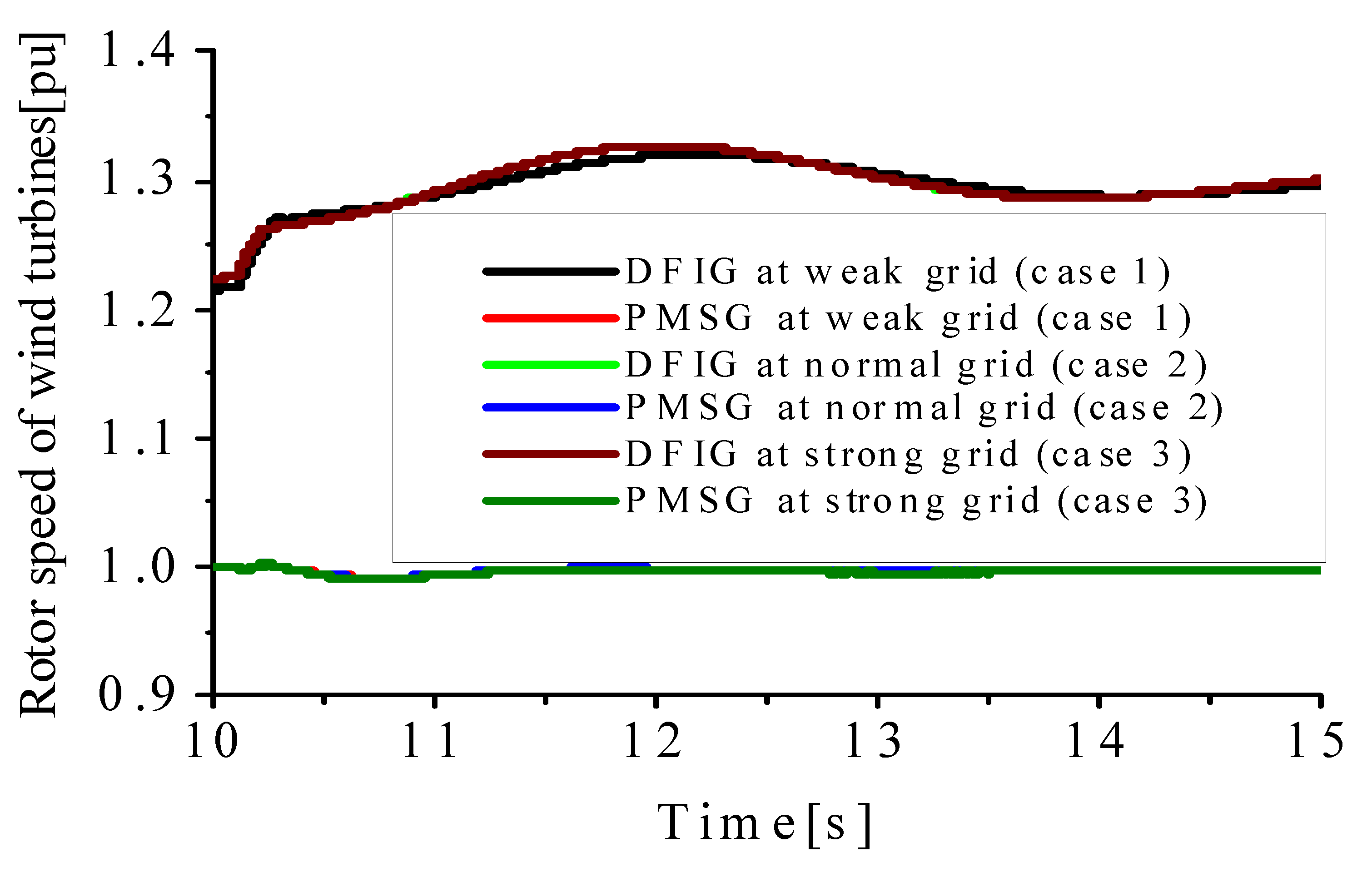
5.1. Operation of the DFIG and PMSG Wind Turbines at Different Grid Strengths

The DFIG and PMSG wind turbines were subjected to the weak grid, normal grid and strong grid, as shown in cases 1 to 3 in Table 2, considering no insertion of the SDBR and no OVPS. Some of the simulation results for the cases considered are shown in Figure 7, Figure 8, Figure 9, Figure 10 and Figure 11.
From Figure 7, the overshoot of the DC-link voltage variable for both wind turbines during the transient state may damage their power converters. The overshoot and time of recovery of the PMSG wind turbine was higher, while the DC-link voltage dip was more for the DFIG, though with a better settling time. The overshoot and Dc-link voltage is more for case 1 (weak grid), compared to the other cases. The responses for the terminal voltage and the active power are shown in Figure 8 and Figure 9, respectively. From Figure 9 and Figure 10, more oscillations were observed for the active and reactive power variables with more oscillations and lower settling time during weak grid periods. However, the effect of the weak grid on the rotor speed of the DFIG wind turbine is negligible, compared to the minimal effect observed in the PMSG wind turbine (Figure 11) during the transient state for weak power grids. The effect of the power grid strengths has more impact on the PMSG than the DFIG. This could be as a result of the full decoupling of the fully rated back-to-back power converter by the network. Consequently, the wind turbines performance in weak grids of case 1 is a critical situation during faulty condition, based on the presented simulation results in Figure 7, Figure 8, Figure 9, Figure 10 and Figure 11. In light of this, the subsequent sections of this paper will consider the improvement of the wind turbines fault ride through in weak grids, considering the employment of SDBR and OVPS schemes.

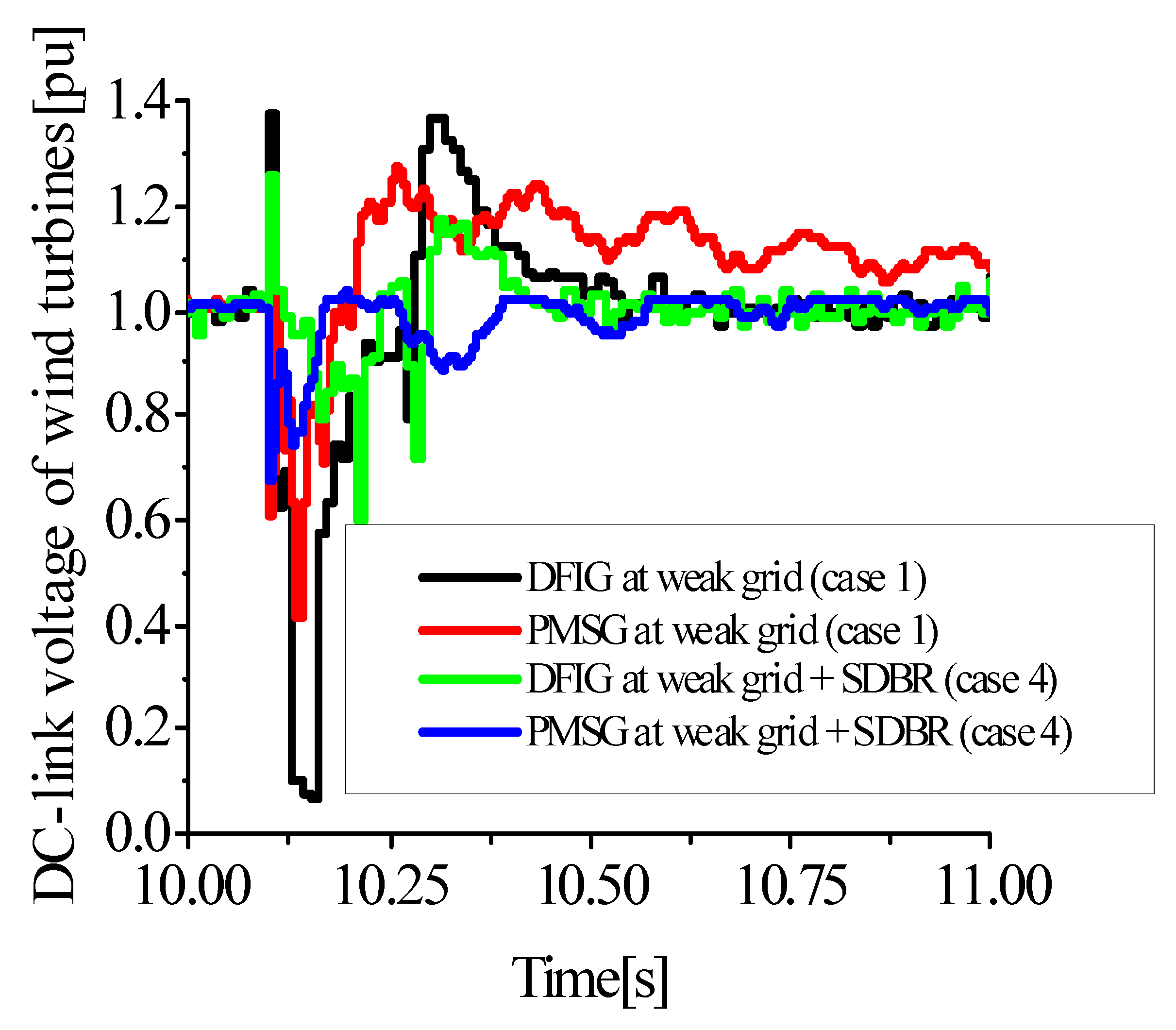
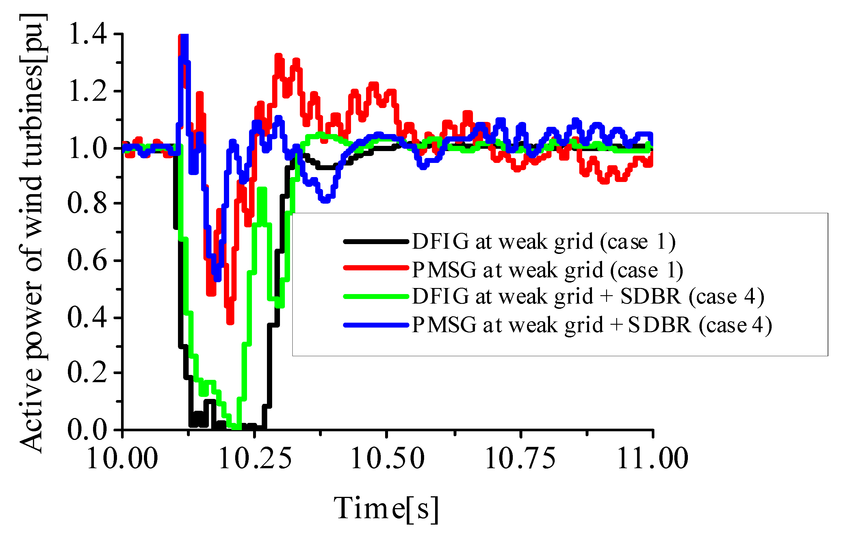
5.2. Improving the Performance of DFIG and PMSG Wind Turbines in Weak Grids Considering the Effective Sizing of SDBR

The performance of the DFIG and PMSG wind turbines in weak grids were further enhanced, considering the use of an effectively sized SDBR, as shown in Table 1. The SDBR was connected at the stator side of both wind turbines for effective comparison during the transient state. In this considered case summarized in Table 2 (cases 1 and 4), no over voltage protection scheme was considered. Some of the simulation results for the key variables of the wind turbines are shown in Figure 12, Figure 13 and Figure 14. The undershoot, overshoot and settling time of the DC-link voltage, terminal voltage and active power of the DFIG and PMSG wind turbine variables without the SDBR connected at the stator were increased, as shown in Figure 12, Figure 13 and Figure 14. In terms of the SDBR on the GSC of both wind turbines, the impacts during fault conditions are on the machines because the stator circuitry of the DFIG and PMSG high voltage are shared by the SDBR, since its connection is series topology. As seen from Figure 12, Figure 13 and Figure 14, the under shoot, overshoot and time of settling for the wind generator variables were much improved, considering the effectively sized SDBR. Consequently, no control loss of power converters is experienced, due to no overvoltage being induced. During operation, the SDBR can significantly mitigate the flow of current, thus avoiding the dangerous overvoltage and high charging current normally experienced in power converters that are vulnerable and fragile in nature.

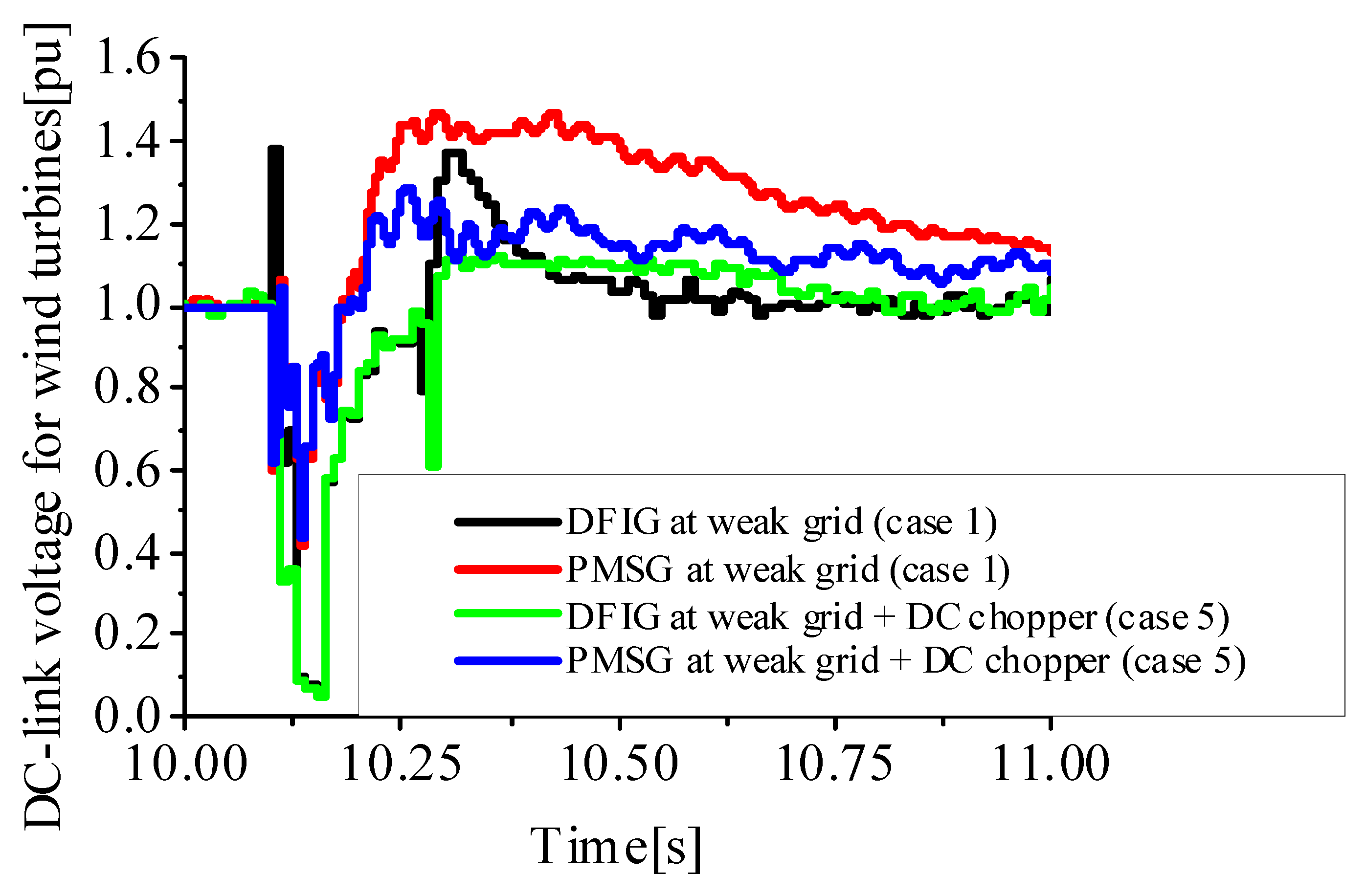
5.3. Improving the Performance of DFIG and PMSG Wind Turbines in Weak Grids Considering over Voltage Protection System (OVPS)

The performance of the DFIG and PMSG wind turbines in weak grids were further enhanced, considering the use of an effectively sized OVPS shown in Table 1. The OVPS is a DC chopper connected at the DC-link of both wind turbines for effective comparison during the transient state. In this considered case summarized in Table 2 (cases 1 and 5), no SDBR scheme was considered. The DC-link voltage variables of the wind turbines are shown in Figure 15. The undershoot, overshoot and settling time of the DC-link voltage of the DFIG and PMSG wind turbine variable without considering OVPS were more than when OVPS was considered. This would protect the power converters of the wind turbines because the wind turbines power converters would be operating within its permissible limits.

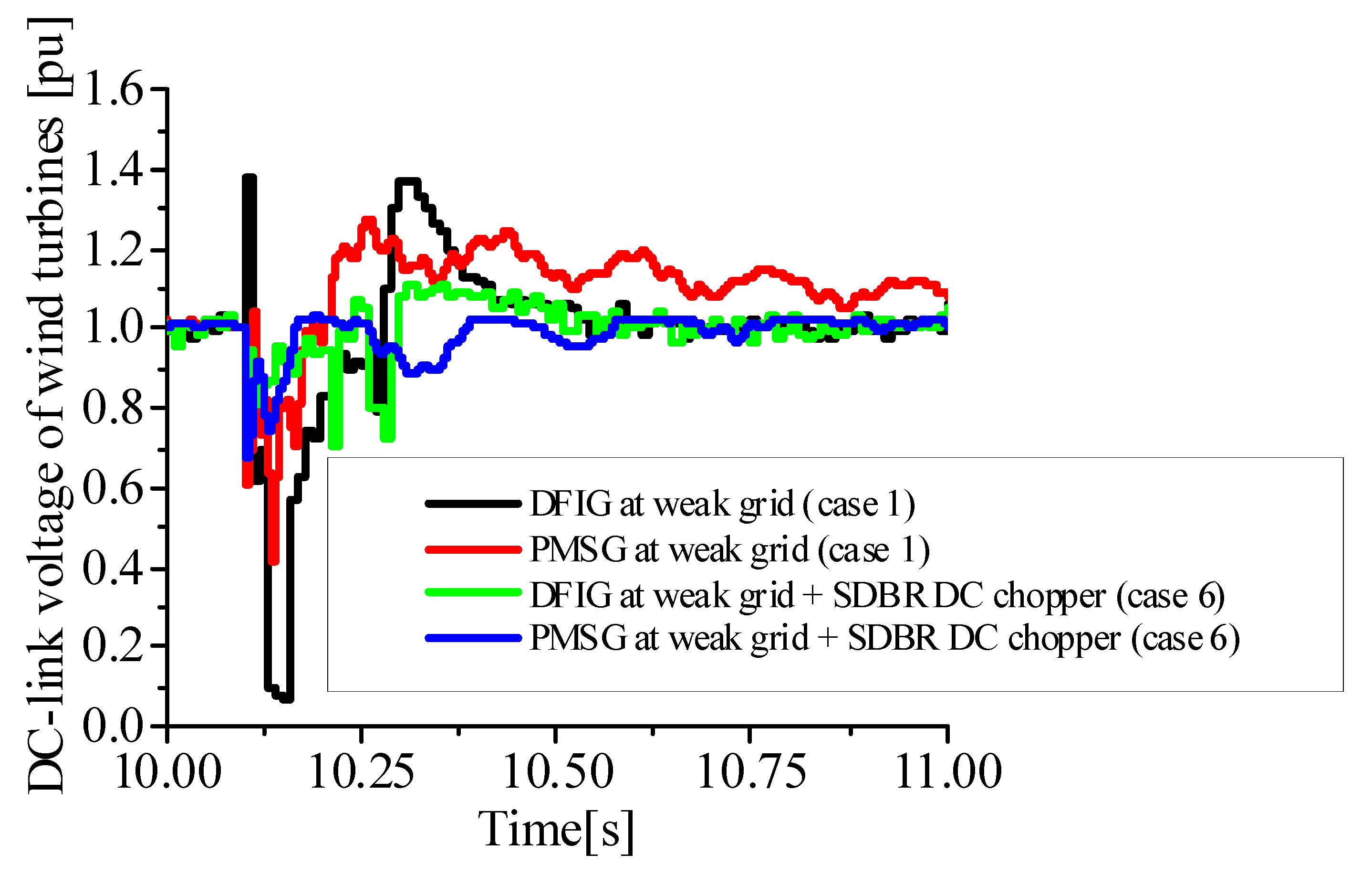
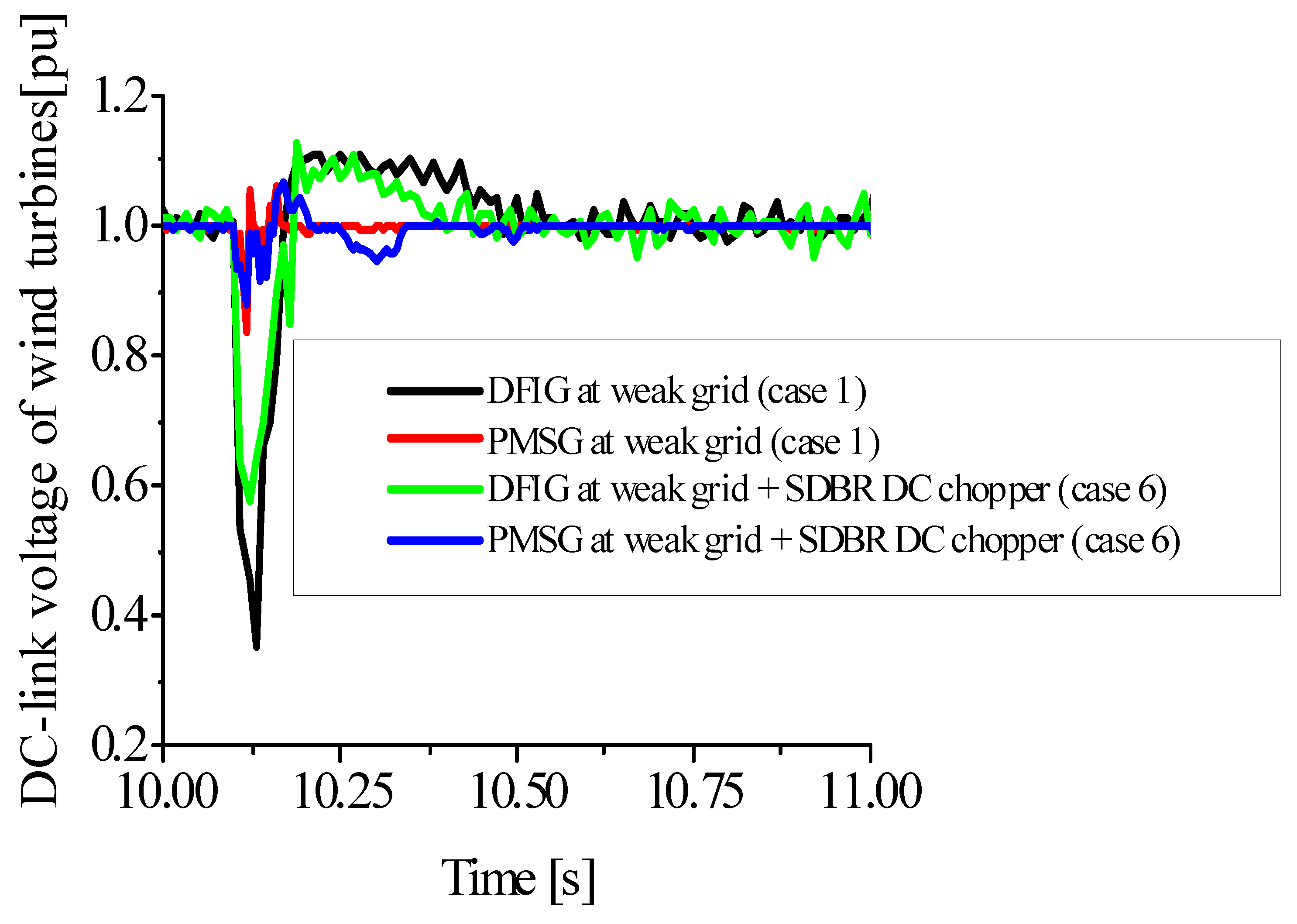
5.4. Improving the Performance of DFIG and PMSG Wind Turbines in Weak Grids Considering SDBR and over Voltage Protection System

The performance of both wind turbines in weak grids were further enhanced, considering the combination of an effectively sized SDBR and OVPS shown in Table 1. In this considered case summarized in Table 2 (cases 1 and 6), a combination of SDBR and OVPS schemes would definitely enhance the wind generators’ variables during operation, as shown in Figure 16. The DC-link voltage variables of the wind turbines are shown in Figure 16 and Figure 17.
The undershoot, overshoot and settling time of the DC-link voltage and terminal voltage of the DFIG and PMSG wind turbines without considering SDBR and OVPS in weak grids were increased, as shown in Figure 16 and Figure 17, respectively. However, in order to improve the fault ride through of the wind turbines, a combination of the SDBR and OVPS would protect the power converters and enhance the variables of the wind turbines. Thus, this type of hybrid fault ride through technique is recommended for variable speed wind turbines operating at weak power grids.

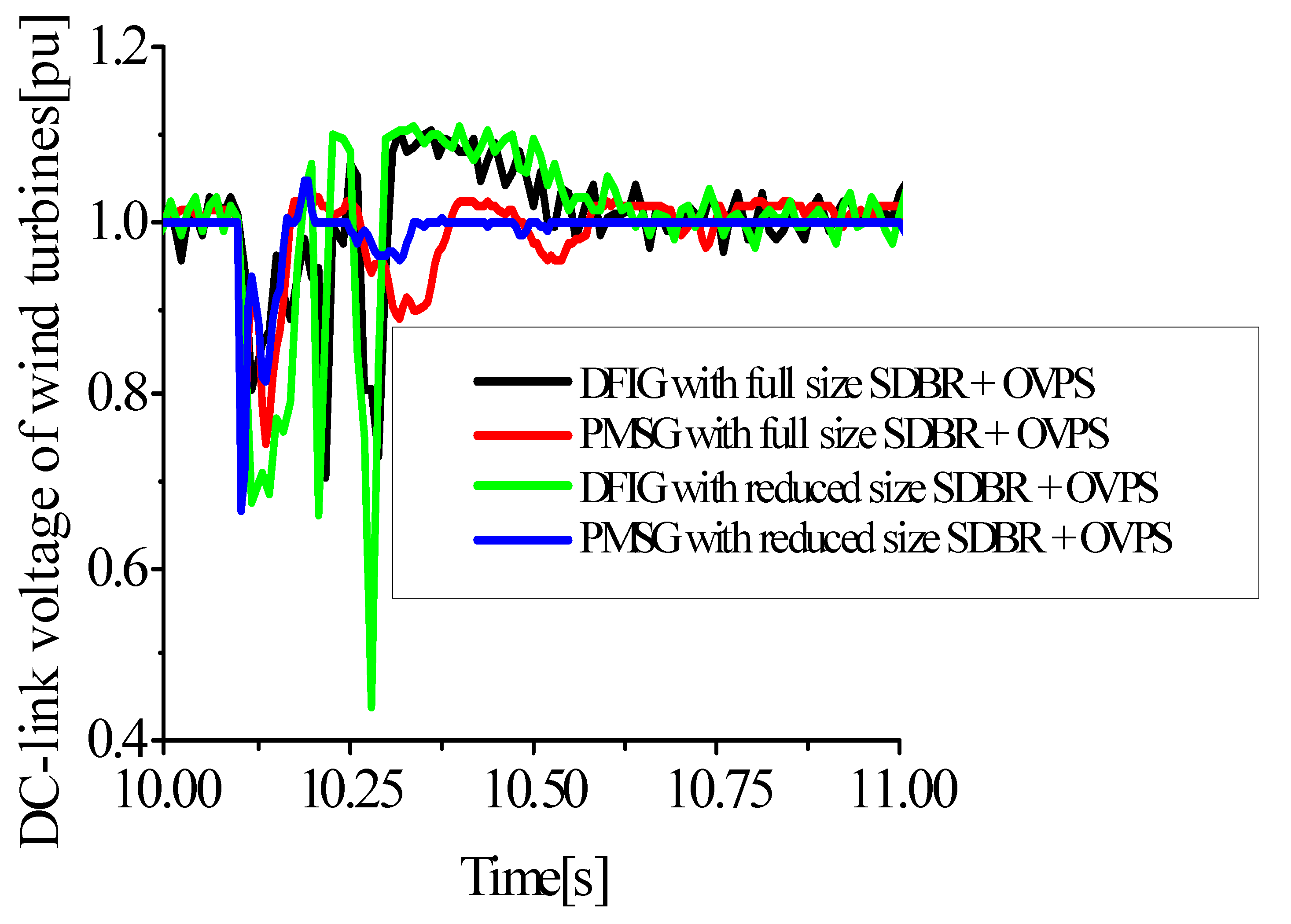
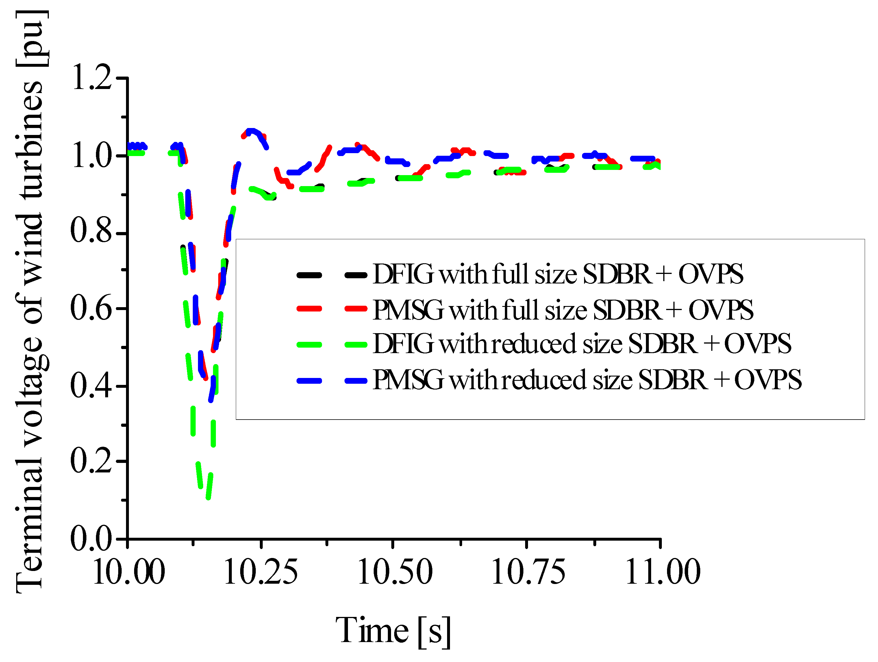
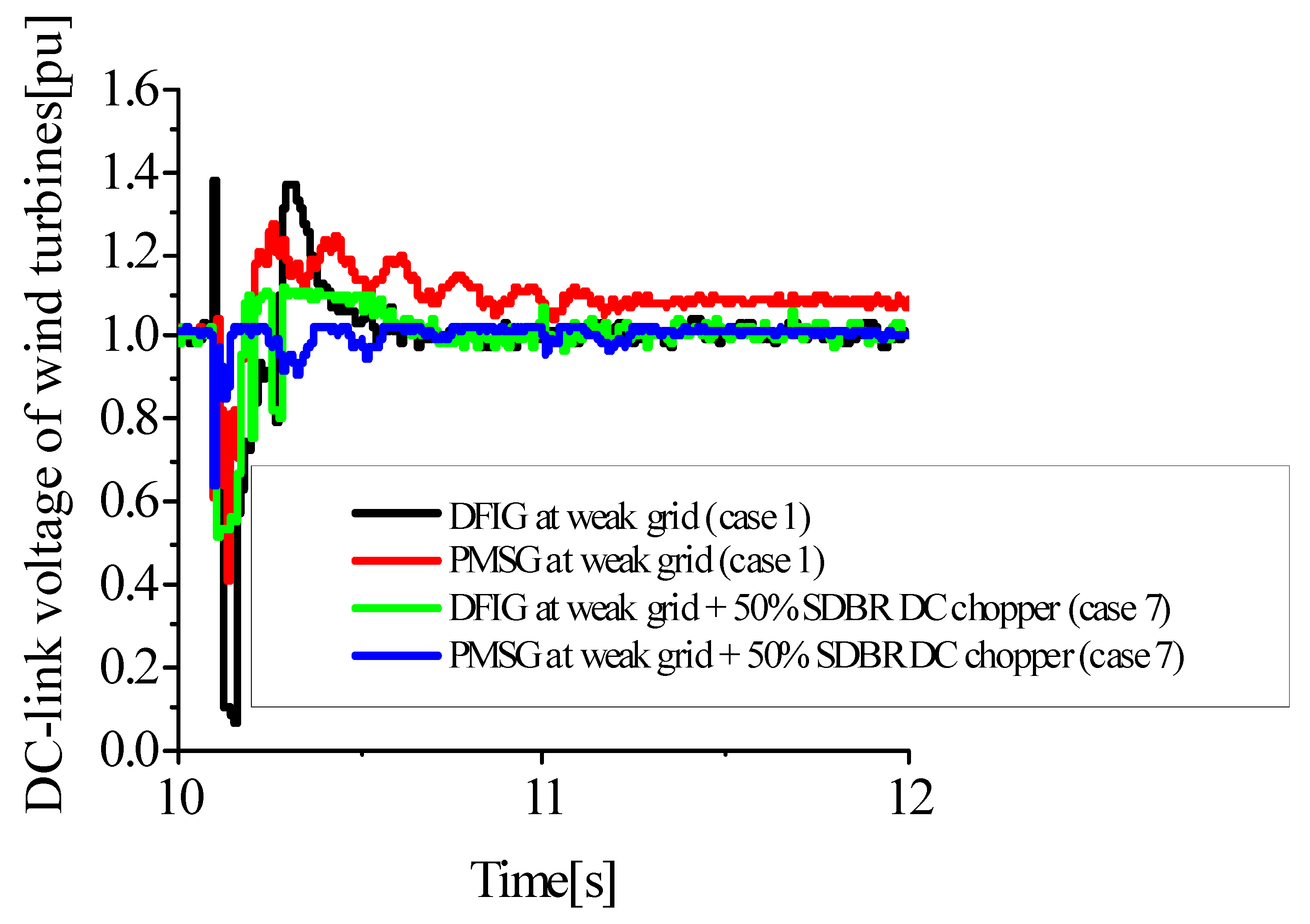
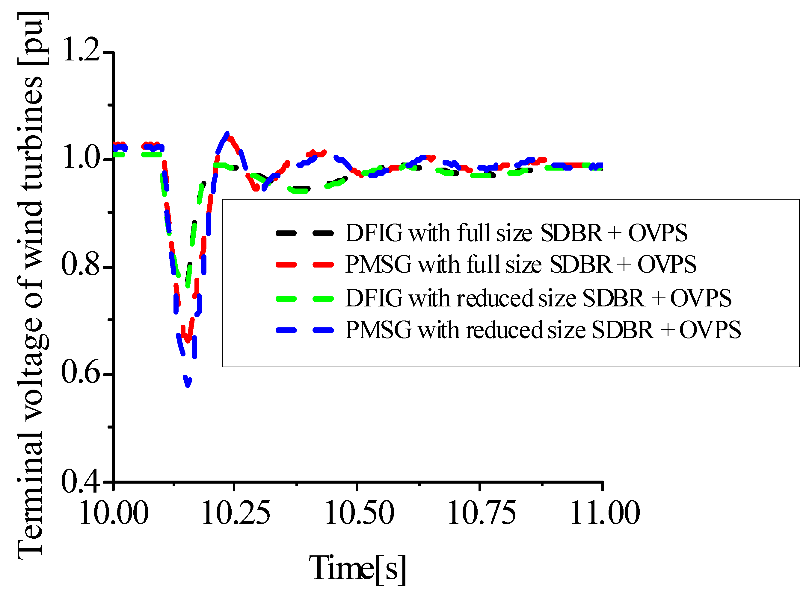
5.5. Improving the Performance of DFIG and PMSG Wind Turbines in Weak Grids Considering 75% and 50% of the Effective SDBR and over Voltage Protection System

The performance of the DFIG and PMSG wind turbines in weak grids were further investigated, considering the combination of 75% and 50% effectively sized SDBR and OVPS shown in Table 1. In this considered case, summarized in Table 2 (cases 1 and 7), the proposed hybrid scheme is proven to enhance the performance of the wind turbines at the transient state, even with a reduction of 75% and 50% of their effective values, as shown in Figure 18 and Figure 19 for 75% reduction and Figure 20 and Figure 21 for 50% reduction, for the DC-link voltage and the terminal voltage of the wind turbines. Thus, it is better to use half of the effective values of the combined schemes than either SDBR or OVPS, since the power converter protection is still within the permissible limit during the transient condition. Thus, this would be a more economical way of improving the fault ride through of the wind turbines.

5.6. Investigating the Performance of DFIG and PMSG Wind Turbines in Weak Grids Considering the Effective SDBR and over Voltage Protection System in a Single Line-to-Ground Fault

The study of the performance of the DFIG and PMSG wind turbines in weak grids were extended for the single line-to-ground fault, which is an example of an unsymmetrical fault, as shown in Figure 22 and Figure 23, respectively. The combination of an effectively sized SDBR and OVPS, shown in Table 1, was considered, as summarized in Table 2 (cases 1 and 6). From the results in Figure 22 and Figure 23, a combination of SDBR and OVPS schemes would definitely improve the performance of the wind generator variables even during unsymmetrical fault conditions, compared to the scenario without the hybrid scheme.
For 50% reduction in the effective SDBR and OVPS during a single line-to-ground unsymmetrical fault, the response for the DC-link voltage and the terminal voltage of the wind turbines are shown in Figure 24 and Figure 25, respectively. From the obtained results, it is better to use half of the effective values of the combined schemes than to use either SDBR or OVPS, as obtained earlier using a severe three-phase to ground fault. This would help in reducing the cost in implementing the fault ride through capabilities of the wind turbines.
As seen from the mathematical dynamics of the SDBR in the wind turbines presented in the paper, the SDBR is closely related to the stator resistance of the wind turbines. Additionally, the maximum power transfer of the GSC of the wind turbines during the transient state would be reduced by the insertion of SDBR in the GSC. Therefore, by reducing the percentage of the SDBR or OVPS, the maximum power transfer would be slightly increased. This means more ratings of the wind generator would be required while keeping the performance satisfactory.

6. Conclusions

A comparative evaluation of the two most commonly employed wind turbines, DFIG and PMSG, with the same machine ratings was presented in this paper. The wind turbines were operated at weak, normal and strong grids to show the influence of the network parameters on the wind turbines. The various strengths of the power grid would affect the performance of both wind turbines. The impact of the power grid strengths was more significant in the DFIG, compared to the PMSG. This is because the PMSG is decoupled at the grid or network side by its power converters that are fully rated with back-to-back topology. The weak power grids would result in a critical situation during faulty conditions, compared to the normal and strong power grids. Consequently, further analysis using the weak power grid was considered in this paper for both wind turbines, considering the use of the series dynamic braking resistor (SDBR) and over voltage protection system (OVPS). The hybrid scheme of the SDBR and OVPS in both wind turbines was able to improve the performance of the variables of the wind turbine and keep the operation of the power converters within their permissible limits. It was observed that, even if there is a 50% reduction in SDBR or OVPS, the performance is still satisfactory, as shown in Section 5.5.
Therefore, it is recommended to use the combination of the SDBR and OVPS with DFIG- or PMSG-based variable speed wind turbines to achieve a superior fault ride through performance, especially in weak grid condition. As a further scope and future direction of study, the controllers of both wind turbines could be enhanced using the Dragonfly Algorithm for better performance during transient conditions.

Author Contributions

Conceptualization, K.E.O.; methodology, K.E.O.; software, S.M.M.; validation, K.E.O. and S.M.M.; formal analysis, K.E.O.; investigation, K.E.O.; writing—original draft, K.E.O.; writing—review & editing, K.E.O.; supervision, S.M.M.; funding acquisition, K.E.O. All authors have read and agreed to the published version of the manuscript.

Funding

No funding was received for this paper.

Conflicts of Interest

The authors declare no conflict of interest.

Abbreviations

X reactance,
R resistance,
Z impedance,
T m torque, N
ρ   air density, k g / m 3
Rradius, m
V w wind speed, m / s 2
C p ( λ , β ) Power coefficient
λ is the ratio of the tip speed
C t is the turbine coefficient
P s is the stator power, Watts
P r is the rotor power, Watts
i q r   quadrature axis rotor current, A
i d r direct axis rotor current, A
Q s stator reactive power, VA
L S stator inductance, H
L m magnetising inductance, H
L r rotor inductance, H
φ s stator flux, T
ω s stator angular frequency, Hz
ω r rotor angular frequency, Hz
σ rotor leakage factor
α , β stationary frames
r ,   s DFIG rotor and stator quantities
gDFIG grid-side converter circuit quantity
Linductance, H
Rresistance,
V d c dc-link voltage, V
P r e f reference power of turbine, W
θrrotor angle position
Isd, Isq,direct and quadrature stator current, A
Vsa*, Vsb*, Vsc*reference abc stator voltages, V
Vsd* and Vsq*reference dq stator voltages, V
Iga, Igb, Igcabc grid currents, A
Vga, Vgb, Vgcabc grid voltages, V
V s + ,       V s components of the stator’s voltage positive and negative sequences, V
τ s time constant of the stator flux, S
ψ s n natural flux, T
v ¯ r o rotor induced voltage
i d , i q dq rectifier’s axes current, A
e d ,   e q dq axes grid voltage, V
ω angular frequency, Hz
β d ,   β q dq rectifier’s modulating signal
r vector norm signal of modulation
E m phase grid voltage amplitude, V
R S D B R resistance of the series dynamic braking resistor,
R L resistance of the load,
P d c available power at the DC, W
P d c _ m a x maximal available power at the DC, W

References

  1. Nduwamungu, A.; Ntagwirumugara, E.; Mulolani, F.; Bashir, W. Fault Ride through Capability Analysis (FRT) in Wind Power Plants with Doubly Fed Induction Generators for Smart Grid Technologies. Energies 2020, 13, 4260. [Google Scholar] [CrossRef]
  2. Qiu, Y.; Feng, Y.; Infield, D. Fault diagnosis of wind turbine with SCADA alarms based multidimensional information processing method. Renew. Energy 2020, 145, 1923–1931. [Google Scholar] [CrossRef]
  3. Okedu, K.E.; Muyeen, S.M.; Takahashi, R.; Tamura, J. Protection schemes for DFIG considering rotor current and DC-link voltage. In Proceedings of the 24th IEEE-ICEMS (International Conference on Electrical Machines and System), Beijing, China, 20–23 August 2011; pp. 1–6. [Google Scholar]
  4. Ouyang, J.; Tang, T.; Yao, J.; Li, M. Active Voltage Control for DFIG-Based Wind Farm Integrated Power System by Coordinating Active and Reactive Powers under Wind Speed Variations. IEEE Trans. Energy Convers. 2019, 34, 1504–1511. [Google Scholar] [CrossRef]
  5. Okedu, K.E.; Muyeen, S.M. Enhanced performance of PMSG Wind Turbines during grid disturbance at different network strengths considering fault current limiter. Int. Trans. Electr. Energy Syst. 2021, 6, e12985. [Google Scholar] [CrossRef]
  6. Shao, H.; Cai, X.; Li, Z.; Zhou, D.; Sun, S.; Guo, L.; Rao, F. Stability Enhancement and Direct Speed Control of DFIG Inertia Emulation Control Strategy. IEEE Access 2019, 7, 120089–120105. [Google Scholar] [CrossRef]
  7. He, X.; Fang, X.; Yu, J. Distributed Energy Management Strategy for Reaching Cost-Driven Optimal Operation Integrated with Wind Forecasting in Multimicrogrids System. IEEE Trans. Syst. Man Cyber. Syst. 2019, 49, 1643–1651. [Google Scholar] [CrossRef]
  8. Qazi, H.W.; Wall, P.; Escudero, M.V.; Carville, C.; Cunniffe, N.; O’Sullivan, J. Impacts of Fault Ride through Behavior of Wind Farms on a Low Inertia System. IEEE Trans. Power Syst. 2020. early access. [Google Scholar] [CrossRef]
  9. Chunli, L.; Zefu, T.; Huang, Q.; Nie, W.; Yao, J. Lifetime Evaluation of IGBT Module in DFIG Considering Wind Turbulence and Nonlinear Damage Accumulation Effect. In Proceedings of the 2019 IEEE 2nd International Conference on Automation, Electronics and Electrical Engineering (AUTEEE), Shenyang, China, 22–24 November 2019. [Google Scholar]
  10. Okedu, K.E.; Muyeen, S.M.; Takahashi, R.; Tamura, J. Wind farms fault ride through using DFIG with new protection scheme. IEEE Trans. Sustain. Energy 2012, 3, 242–254. [Google Scholar] [CrossRef] [Green Version]
  11. El-Sattar, A.A.; Saad, N.H.; El-Dein, M.Z.S. Dynamic response of doubly fed induction generator variable speed wind turbine under fault. Electr. Power Syst. Res. 2008, 78, 1240–1246. [Google Scholar] [CrossRef]
  12. Okedu, K.E.; Barghash, H. Enhancing the Performance of DFIG Wind Turbines Considering Excitation Parameters of the Insulated Gate Bipolar Transistors and a New PLL Scheme. Front. Energy Res.-Smart Grids 2021, 8, 620277. [Google Scholar] [CrossRef]
  13. Dattaa, S.; Mishrab, J.P.; Royb, A.K. Grid connected DFIG based wind energy conversion system using nine switch converter. J. Appl. Res. Technol. 2021, 17, 859. [Google Scholar] [CrossRef]
  14. Okedu, K.E.; Muyeen, S.M.; Takahashi, R.; Tamura, J. Use of Supplementary Rotor Current Control in DFIG to Augment Fault Ride through of Wind Farm as per Grid Requirement. In Proceedings of the 37th Annual Conference of IEEE Industrial Electronics Society (IECON 2011), Melbourne, Australia, 7–10 November 2011. [Google Scholar]
  15. Okedu, K.E.; Muyeen, S.M.; Takahashi, R.; Tamura, J. Improvement of Fault Ride Through Capability of Wind Farm using DFIG Considering SDBR. In Proceedings of the 14th European Conference of Power Electronics EPE, Birmingham, UK, 30 August–1 September 2011; pp. 1–10. [Google Scholar]
  16. Okedu, K.E. Enhancing DFIG Wind Turbine during Three-phase Fault Using Parallel Interleaved Converters and Dynamic Resistor. IET Renew. Power Gener. 2016, 10, 1211–1219. [Google Scholar] [CrossRef]
  17. Okedu, K.E.; Muyeen, S.M.; Takahashi, R.; Tamura, J. Participation of FACTS in Stabilizing DFIG with Crowbar during Grid Fault Based on Grid Codes. In Proceedings of the 6th IEEE-GCC Conference and Exhibition, Dubai, United Arab Emirates, 19–22 February 2011; pp. 365–368. [Google Scholar]
  18. Boujoudi, B.; Kheddioui, E.; Machkour, N.; Achalhi, A.; Bezza, M. Comparative study between different types of control of the wind turbine in case of voltage dips. In Proceedings of the 2018 Renewable Energies, Power Systems & Green Inclusive Economy (REPS-GIE), Casablanca, Morocco, 23–24 April 2018; pp. 1–5. [Google Scholar]
  19. Okedu, K.E.; Muyeen, S.M.; Takahashi, R.; Tamura, J. Comparative Study between Two Protection Schemes for DFIG-based Wind Generator. In Proceedings of the 23rd IEEE-ICEMS (International Conference on Electrical Machines and Systems), Seoul, Republic of Korea, 31 October–3 November 2010; pp. 62–67. [Google Scholar]
  20. Okedu, K.E.; Muyeen, S.M.; Takahashi, R.; Tamura, J. Stabilization of wind farms by DFIG-based variable speed wind generators. In Proceedings of the International Conference of Electrical Machines and Systems (ICEMS), Seoul, Republic of Korea, 10–13 October 2010; pp. 464–469. [Google Scholar]
  21. Bekakra, Y.; Attous, D.B. Sliding Mode Controls of Active and Reactive Power of a DFIG with MPPT for Variable Speed Wind Energy Conversion. Aust. J. Basic Appl. Sci. 2011, 5, 2274–2286. [Google Scholar]
  22. Ali, D.M.; Jemli, K.; Jemli, M.; Gossa, M. Doubly Fed Induction Generator, with Crowbar System under Micro-Interruptions Fault. Int. J. Electr. Eng. Inform. 2010, 2, 216–231. [Google Scholar]
  23. Suthar, D.B. Wind Energy Integration for DFIG Based Wind Turbine Fault Ride Through. Indian J. Appl. Res. 2014, 4, 216–220. [Google Scholar] [CrossRef]
  24. Lamchich, M.T.; Lachguer, N. Matlab Simulink as Simulation Tool for Wind Generation Systems Based on Doubly Fed Induction Machines. In MATLAB-A Fundamental Tool for Scientific Computing and Engineering Applications; Intech Publishing: Rijeka, Croatia, 2012; Volume 2, Chapter 7; pp. 139–160. [Google Scholar]
  25. Noubrik, A.; Chrifi-Alaoui, L.; Bussy, P.; Benchaib, A. Analysis and Simulation of a 1.5MVA Doubly Fed Wind Power in Matlab Sim PowerSystems using Crowbar during Power Systems Disturbances. In Proceedings of the IEEE-2011 International Conference on Communications, Computing and Control Applications (CCCA), Hammamet, Tunisia, 3–5 March 2011. [Google Scholar]
  26. Nasiri, M.; Mohammadi, R. Peak current limitation for grid-side inverter by limited active power in PMSG-based wind turbines during different grid faults. IEEE Trans. Sustain. Energy 2017, 8, 3–12. [Google Scholar] [CrossRef]
  27. Gencer, A. Analysis and control of fault ride through capability improvement PMSG based on WECS using active crowbar system during different fault conditions. Elektron. Elektrotech. 2018, 24, 64–69. [Google Scholar] [CrossRef] [Green Version]
  28. Yehia, D.M.; Mansour, D.A.; Yuan, W. Fault ride-through enhancement of PMSG wind turbines with DC microgrids using resistive-type SFCL. IEEE Trans. Appl. Supercond. 2018, 28, 1–5. [Google Scholar] [CrossRef] [Green Version]
  29. Strachan, N.P.W.; Jovcic, D. Stability of a variable-speed permanent magnet wind generator with weak ac grids. IEEE Trans. Power Deliv. 2010, 25, 2779–2788. [Google Scholar] [CrossRef]
  30. Hu, J.; Huang, Y.; Wang, D.; Yuan, H.; Yuan, X. Modeling of grid-connected DFIG-based wind turbines for dc-link voltage stability analysis. IEEE Trans. Sustain. Energy 2015, 6, 1325–1336. [Google Scholar] [CrossRef]
  31. Zhou, Y.; Nguyen, D.D.; Kjr, P.C.; Saylors, S. Connecting wind power plant with weak grid–challenges and solutions. In Proceedings of the 2013 IEEE Power Energy Society General Meeting, Vancouver, BC, Canada, 21–25 July 2013; pp. 1–7. [Google Scholar]
  32. Garcia-Garcia, M.; Comech, M.P.; Sallan, J.; Liombart, A. Modelling Wind Farms for Grid Disturbances Studies. Science direct. Renew. Energy 2008, 33, 2019–2121. [Google Scholar]
  33. Okedu, K.E.; Muyeen, S.M.; Takahashi, R.; Tamura, J. Application of SDBR with DFIG to Augment Wind Farm Fault Ride Through. In Proceedings of the 24th IEEE-ICEMS (International Conference on Electrical Machines and Systems), Beijing, China, 20–23 August 2011; pp. 1–6. [Google Scholar]
  34. Okedu, K.E. Enhancing the performance of DFIG variable speed wind turbine using parallel integrated capacitor and modified modulated braking resistor. IET Gener. Transm. Distrib. 2019, 13, 3378–3387. [Google Scholar] [CrossRef]
  35. Okedu, K.E. Improving the transient performance of DFIG wind turbine using pitch angle controller low pass filter timing and network side connected damper circuitry. IET Renew. Power Gener. 2020, 14, 1219–1227. [Google Scholar] [CrossRef]
  36. Zubia, I.; Ostolaza, J.X.; Susperrgui, A.; Ugartemendia, J.J. Multi-machine transient modeling of wind farms, an essential approach to the study of fault conditions in the distribution network. Appl. Energy 2012, 89, 421–429. [Google Scholar] [CrossRef]
  37. Okedu, K.E. Enhancing the Transient Performance of DFIG Wind Turbine with Supercapacitor Control Strategy. In Proceedings of the 2022 IEEE 31st International Symposium on Industrial Electronics (ISIE), Paper ISIE22-000118. Anchorage, AK, USA, 31 May–3 June 2022; Volume 31, pp. 92–97. [Google Scholar]
  38. Okedu, K.E. Augmentation of DFIG and PMSG Wind Turbines Transient Performance Using Different Fault Current Limiters. Energies 2022, 15, 4817. [Google Scholar] [CrossRef]
  39. Priyadarshi, N.; Ramachandaramurthy, V.; Padmanaban, S.; Azam, F. An ant colony optimized MPPT for standalone hybrid PV-wind power system with single Cuk converter. Energies 2019, 12, 167. [Google Scholar] [CrossRef] [Green Version]
  40. Lee, S.W.; Chun, K.H. Adaptive sliding mode control for PMSG wind turbine systems. Energies 2019, 12, 595. [Google Scholar] [CrossRef] [Green Version]
  41. Heier, S. Wind energy conversion systems. In Grid Integration of Wind Energy Conversion Systems; John Wiley & Sons Ltd.: Chicester, UK, 1998; pp. 34–36. [Google Scholar]
  42. MATLAB Documentation Center. Available online: http://www.mathworks.co.jp/jp/help/ (accessed on 12 March 2012).
  43. Muyeen, S.M.; Al-Durra, A.; Tamura, J. Variable speed wind turbine generator system with current controlled voltage source inverter. Energy Convers. Manag. 2011, 52, 2688–2694. [Google Scholar] [CrossRef] [Green Version]
  44. Li, S.; Haskew, T.A.; Xu, L. Conventional and novel control design for direct driven PMSG wind turbines. Electr. Power Syst. Res. 2010, 80, 328–338. [Google Scholar] [CrossRef]
  45. Yang, D.; Ruan, X.; Wu, H. Impedance shaping of the grid-connected inverter with LCL filter to improve its adaptability to the weak grid condition. IEEE Trans. Power Electron. 2014, 29, 5795–5805. [Google Scholar] [CrossRef]
  46. Thierry, C.V. Voltage Stability of Electric Power Systems; Springer: Berlin, Germany, 1998. [Google Scholar]
  47. Grunau, S.; Fuchs, W.F. Effect of Wind-Energy Power Injection into Weak Grids; Institute for Power Electronics and Electrical Drives, Christian-Albrechts-University of Kiel: Kiel, Germany, 2012; pp. 1–7. [Google Scholar]
  48. PSCAD/EMTDC Manual, Version 4.6.0; Manitoba HVDC Lab.: Winnipeg, MB, Canada, 2016.
Figure 1. The DFIG wind turbine characteristics.
Energies 15 09228 g001
Figure 2. The rotor side converter control circuit of the DFIG.
Energies 15 09228 g002
Figure 3. The grid side converter control circuit of the DFIG.
Energies 15 09228 g003
Figure 4. The PMSG wind turbine characteristics.
Energies 15 09228 g004
Figure 5. The rotor side converter control circuit of the PMSG.
Energies 15 09228 g005
Figure 6. The grid side converter control circuit of the PMSG.
Energies 15 09228 g006
Figure 7. DC-link voltage of wind turbines at different grid strengths (cases 1, 2, 3).
Energies 15 09228 g007
Figure 8. Terminal voltage of wind turbines at different grid strengths (cases 1, 2, 3).
Energies 15 09228 g008
Figure 9. Active power of wind turbines at different grid strengths (cases 1, 2, 3).
Energies 15 09228 g009
Figure 10. Reactive power of wind turbines at different grid strengths (cases 1, 2, 3).
Energies 15 09228 g010
Figure 11. Rotor speed of wind turbines at different grid strengths (cases 1, 2, 3).
Energies 15 09228 g011
Figure 12. DC-link voltage of wind turbines with SDBR at weak grid (cases 1 and 4).
Energies 15 09228 g012
Figure 13. Terminal voltage of wind turbines with SDBR at weak grid (cases 1 and 4).
Energies 15 09228 g013
Figure 14. Active power of wind turbines with SDBR at weak grid (cases 1 and 4).
Energies 15 09228 g014
Figure 15. DC-link voltage of wind turbines with OVPS at weak grid (cases 1 and 5).
Energies 15 09228 g015
Figure 16. DC-link voltage of wind turbines with SDBR and OVPS at weak grid (cases 1 and 6) for three-line-to-ground fault.
Energies 15 09228 g016
Figure 17. Terminal voltage of wind turbines with SDBR and OVPS at weak grid (cases 1 and 6) for three-line-to-ground fault.
Energies 15 09228 g017
Figure 18. DC-link voltage of wind turbines with 75% SDBR and OVPS at weak grid (cases 1 and 7).
Energies 15 09228 g018
Figure 19. Terminal voltage of wind turbines with 75% SDBR and OVPS at weak grid (cases 1 and 7).
Energies 15 09228 g019
Figure 20. DC-link voltage of wind turbines with 50% SDBR and OVPS at weak grid (cases 1 and 7) for three-line-to-ground fault.
Energies 15 09228 g020
Figure 21. Terminal voltage of wind turbines with 50% SDBR and OVPS at weak grid (cases 1 and 7) for three-line-to-ground fault.
Energies 15 09228 g021
Figure 22. DC-link voltage of wind turbines with SDBR and OVPS at weak grid (cases 1 and 6) for single-line-to-ground fault.
Energies 15 09228 g022
Figure 23. Terminal voltage of wind turbines with SDBR and OVPS at weak grid (cases 1 and 6) for single-line-to-ground fault.
Energies 15 09228 g023
Figure 24. DC-link voltage of wind turbines with 50% SDBR and OVPS at weak grid (cases 1 and 7) for single-line-to-ground fault.
Energies 15 09228 g024
Figure 25. Terminal voltage of wind turbines with 50% SDBR and OVPS at weak grid (cases 1 and 7) for single-line-to-ground fault.
Energies 15 09228 g025
Table 1. Rating of the parameters of the wind turbines.
DFIG Wind TurbinePMSG Wind Turbine
rated power5.0 MWrated power5.0 MW
stator resistance0.01 pustator resistance0.01 pu
d-axis reactance1.0 pud-axis reactance1.0 pu
q-axis reactance0.7 puq-axis reactance0.7 pu
machine inertia (H)3.0machine inertia (H)3.0
effective DC-link protection0.2 effective DC-link protection 0.2
effective SDBR0.01 pueffective SDBR0.05 pu
over voltage protection system (OVPS)110%over voltage protection system (OVPS)110%
Table 2. Wind turbines operation at different grid strengths.
CasesGrid StrengthSCRDFIGPMSG
1Weak4No SDBR
No OVPS
No SDBR
No OVPS
2Normal8No SDBR
No OVPS
No SDBR
No OVPS
3Strong12No SDBR
No OVPS
No SDBR
No OVPS
4Weak4With effective SDBR
No OVPS
With effective SDBR
No OVPS
5Weak4No SDBR
With effective OVPS
No SDBR
With effective OVPS
6Weak4With effective SDBR
With effective OVPS
With effective SDBR
With effective OVPS
7Weak4With 50% effective SDBR and OVPSWith 50% effective SDBR and OVPS
Publisher’s Note: MDPI stays neutral with regard to jurisdictional claims in published maps and institutional affiliations.

