Abstract
Industrial liquid/solid fluidized bed heat exchangers are commonly used with particle recycling systems to allow an increased superficial velocity and higher heat transfer rates. Here, experimental results are reported on a novel helical flow channel geometry for liquid/solid fluidized beds which allow higher heat transfer rates and reduced complexity by operating below the particle transport fluid velocity. This eliminates the complexity of particle recycle systems whilst still delivering a compact heat exchanger. The qualitative character of the fluidization was studied for a range of particle types and sizes under several inclinations of the helices and various hydraulic diameters. The best fluidization combinations were further studied to obtain heat transfer coefficients and pressure drops. Improvements over the heat exchange from a plain concentric tube in an annulus were obtained to the following degree: vertical fluidized bed, 27%; helical baffles, 34 to 54%; and fluidized bed with helical baffles, 69 to 89%.
1. Introduction
Liquid/solid fluidized beds are well known for their characteristics of providing a self-cleaning effect when the fluidizing phase is a liquid with a propensity to deposit scale or fouling on the surfaces submerged in the bed. When such surfaces are employed for heat exchange, not only are they kept clean, but the heat transfer coefficients obtained are significantly higher than would be the case without the fluidized bed. However, to obtain high enough heat transfer rates to be commercially viable, it is usually necessary to use superficial velocities, for the continuous phase, which are in the particle transport regime. Consequently, such heat exchange systems are equipped with particle separation and recycling systems. These systems need to be controlled to ensure that the particle recycle rate is appropriate to maintain the desired porosity in the bed and to minimize the amount of continuous phase that is recycled. Both the particles and the continuous phase (about 40% of the volume of recycled material) would be approximately at the exit temperature of the heat exchanger and be mixed with the main inlet flow, thus affecting the approach temperatures and thermodynamic efficiency of the heat exchanger in a disadvantageous manner. Klaren recognizes that this is a disadvantage in recirculating particles and the associated fluid [1].
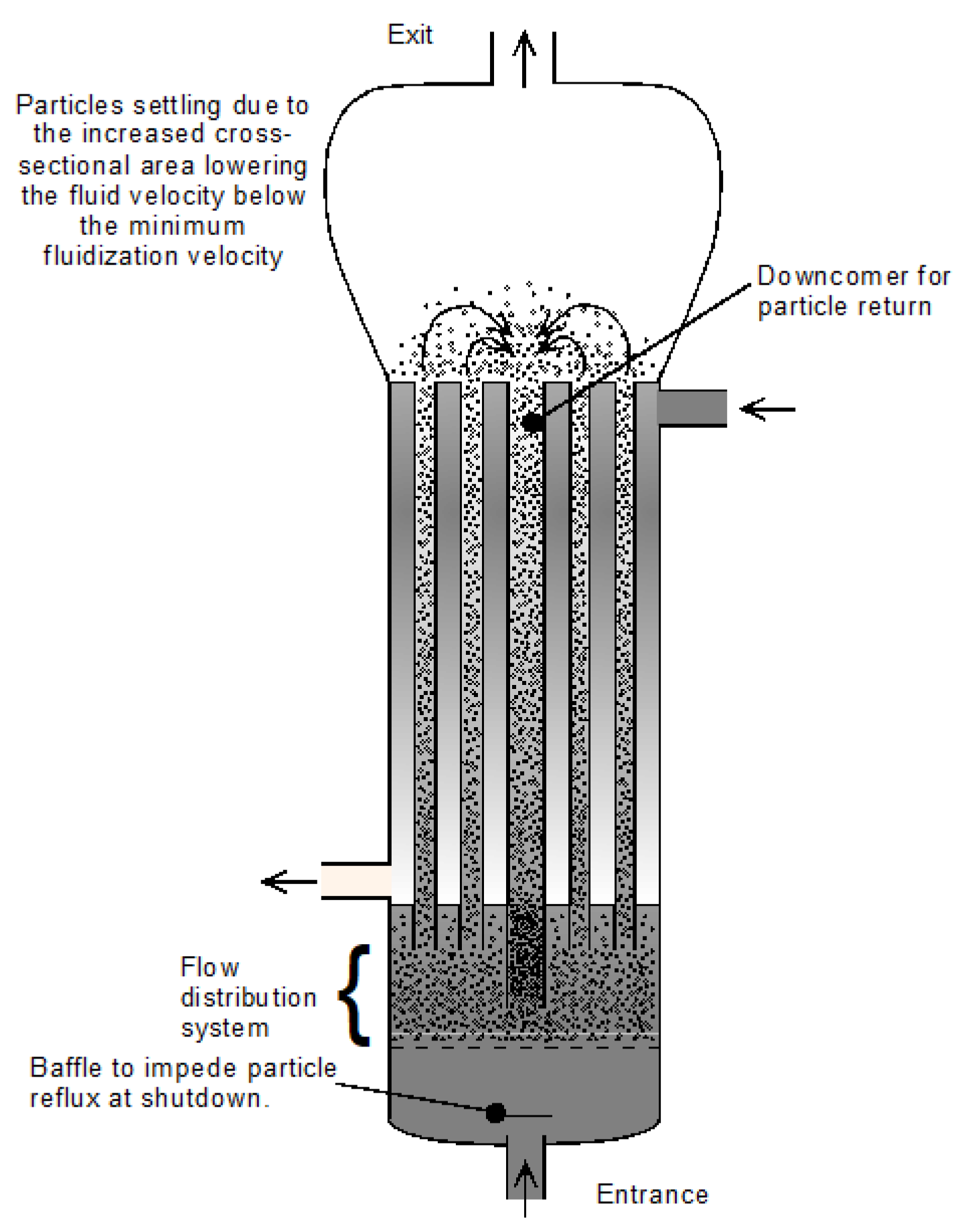
Notwithstanding the above-mentioned thermodynamic disadvantage, there has been considerable development work over a significant period. One of the earliest designs was that of Klaren who proposed an internal recycle system with a central return duct and multiple small diameter beds in tubes within a shell or multiple external recycle ducts, both with control valves to avoid liquid short circuiting [2] (Figure 1). Over an appreciable period, Klaren [3,4,5,6,7,8] developed a series of means of controlling and improving the behavior of the particle recycling with ever more sophisticated and complex schemes including mechanically driven systems of valves, screw conveyors, etc. The increasing complexity of these proposed systems shows that the practical implementation of particle re-circulation is difficult and not fully resolved.
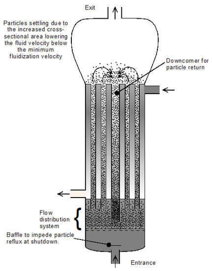
Figure 1.
Liquid/solid fluidized bed heat exchanger with internal particle re-circulation.
Fluidized bed continuous phase superficial velocities can be increased by several methods, as discussed below. The one mentioned above is that of operating a bed in the transport regime. Beds can also have their apparent gravitational force increased by using a cylindrical geometry with a radial inflow of the continuous phase whilst under rotation around a vertical axis [9]. This arrangement, at the cost of considerable mechanical complexity, can increase the apparent gravity (centripetal force) that the bed is subjected to, by several multiples of normal gravitation force. It has been successfully demonstrated in gas–solid fluidized bed combustors with up to 100 g centripetal force. In the work reported by Demircan et al., heat transfer coefficients were not measured directly, but combustion intensity was measured at almost an order of magnitude higher than a normal vertical fluidized bed combustor at atmospheric pressure. The heat transfer rates were calculated for various fuels. These were for a gas/solid fluidized bed and thus difficult to compare with those of a liquid/solid bed. The heat transfer coefficient was found to be proportional to the apparent gravity to the power of one fifth (g0.2). For liquid/solid fluidization in a centrifugal field, there are no experimental studies of heat transfer; however, some studies of the hydrodynamics have been carried out, including those by Margraf and Werther [10,11]. In their work, it can be seen that although the pseudo gravitational acceleration (i.e., the centripetal force) achieved was in the range 20 to 500 g, the system was mechanically highly complex even without heat transfer elements. If centrifugally enhanced fluidized bed heat exchangers were to be developed, the Achilles’ heel would be the reliability and maintenance caused by the rotating seals and drives.
O’Dea et al. [12] experimented with gas/solid fluidization of fine particles in an inclined tube. The particle diameters ranged from 0.06 to 0.5 mm with densities in the range 1450 to 2620 kg/m3. The tube diameter was 83 mm, which gave ratios of particle to tube diameter from 7.2 × 10⁻⁴ to 6 × 10⁻³. They identified three flow regimes from a fixed bed to a channeled bed with inclinations between 45° and vertical. However, the authors concluded that the applicability of their model needed to be confirmed for a wider range of properties. Their results could not be directly applied to liquid/solid fluidized beds. A prior study by Zenz, which was summarized by Zabrodsky [13], reported a similar classification of flow regimes in inclined tubes for pneumatic transport of particulate solids.
Galvin and Nguyentranlam [14] observed that inclined parallel plates in a liquid/solid fluidized bed allow a wide range of bed porosities and fluid speeds higher than the particles’ terminal velocities. The option of operating a liquid/solid fluidized bed in a tilted vessel with flow vectors in both the horizontal and vertical directions would be expected to allow higher continuous phase flow speeds with a lower vertical velocity component. The vertical component of the flow velocity is that which predominantly provides the fluidizing effect. Thus, higher superficial velocities over immersed heat transfer surfaces could be obtained without entering a particle transport regime.
Hudson et al. [15] reported the velocity profiles in liquid/solid fluidized beds with a maximum inclination of 10° from the vertical and showed a solids re-circulation pattern that favored mixing of the particles. Yakubov et al. [16] reported up to a 30% increase in the critical velocity for bed escape with an inclination of 45° of a cylindrical liquid/solid fluidized bed. It was also found that the fluidization in an inclined cylinder developed recirculation cells with regions of very low particle concentrations between such cells.
Murata et al. [17] found that an inclined gas/solid fluidized bed at 15° to the vertical can have substantially increased heat transfer coefficients for electrically heated plates with the same inclination as the tube containing the bed, compared to the vertical state. The authors attributed some of the increase to the higher level of contact between heater plates and particles in the inclined case. Ashok Kumar et al. [18] carried out a study of the inclination of a tube with liquid/solid fluidization in order to ascertain the maximum angle at which a homogenous fluidization could be sustained. They used 1.5 mm diameter sand particles and inclinations from 30° to 90° to the horizontal. They reported five types of flow patterns and concluded that 70° to the horizontal was the minimum angle to sustain fluidizing conditions for inclined pipe connectors in process industries.
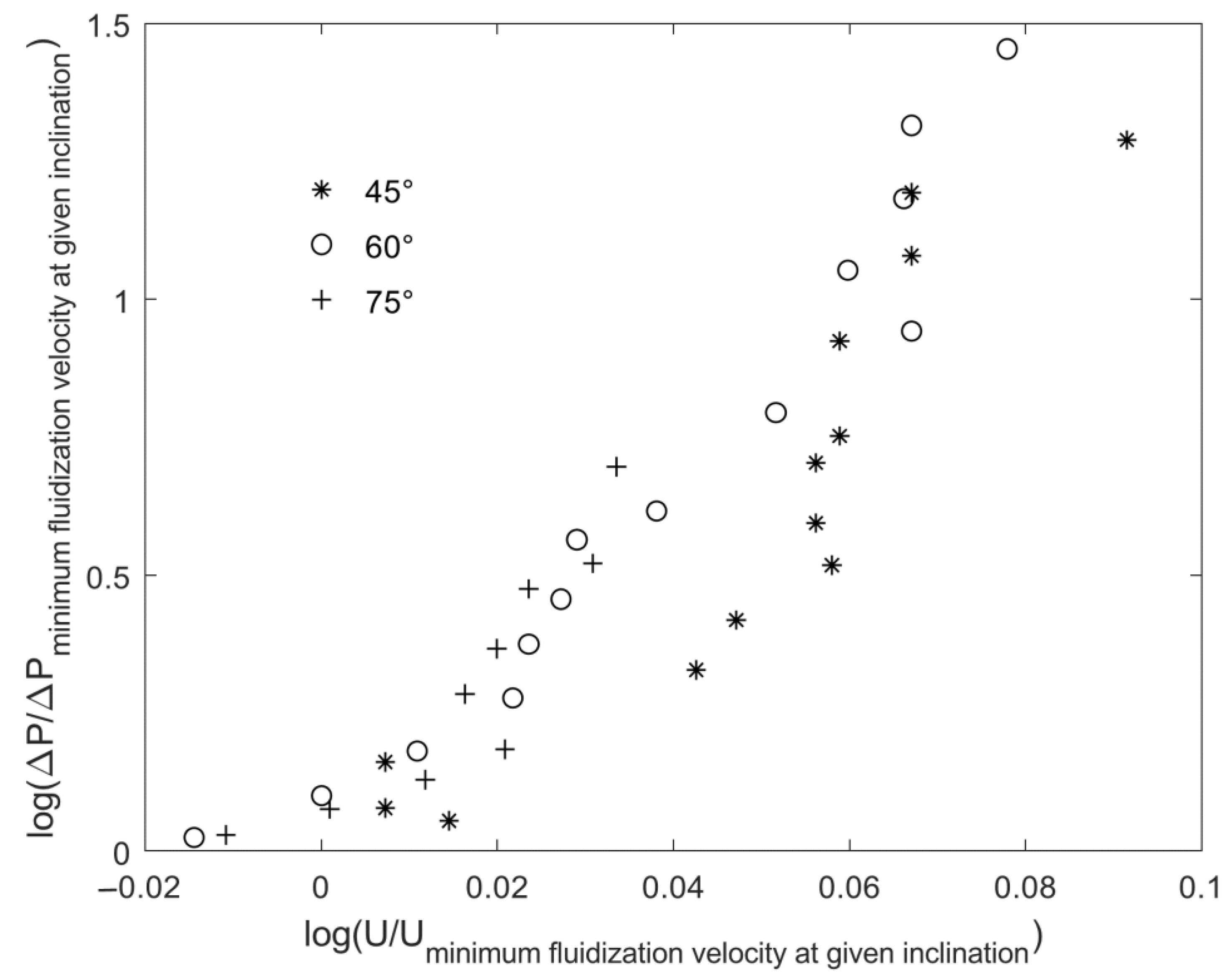
Chong et al. [19] researched flow regimes for a liquid/solid fluidized bed in an inclined pipe and identified four conditions: fixed bed, initial fluidization, partial fluidization and fully fluidized bed. They covered inclinations of 45°, 60° and 70° for water/solid systems with glass particles from 0.42 to 0.5 mm diameter in a 76 mm internal diameter tube. They found that the initial fluidization velocity for both gas/solid and liquid/solid has the same ratio to the vertical bed minimum fluidization velocity for a given angle of inclination. The authors developed models of the relationship between the behavior of a vertical bed and inclined beds for fluidization velocities and pressure drops. They showed that the ratio of complete fluidization velocity to minimum fluidization velocity is always greater for a given inclined bed in liquid/solid systems than it is in gas/solid systems. A linear relationship on a log–log plot between the ratio of fluidized pressure drop to minimum fluidization pressure drop and the ratio of superficial velocity to minimum fluidization velocity was shown. Figure 2 shows the Chong et al. data plotted in function of the ratio of fluid velocity to minimum fluidization velocity for the specific inclination and the corresponding ratio of pressure drops instead of the original form where the data were plotted as ratios to the vertical bed minimum fluidization conditions for all the inclinations. Each inclination should be considered as a different flow channel geometry and so the behavior of the bed should be compared to the minimum fluidization conditions of that particular inclination, rather than that of the vertical bed. It should be noted that for industrial liquid/solid fluidized bed heat exchangers, the particle sizes employed are much larger and the flow channels much narrower than those used by Chong et al. It can be observed that the data do not extend to velocity ratios (U/U minimum fluidization for given inclination) of more than 1.25.

Figure 2.
Chong et al. re-plotted as a function of minimum fluidization velocity and pressure drop for each inclination, instead of considering that of a vertical bed as the reference condition.
Similarly, Figure 3 shows the data from Yakubov et al.’s work (Figure 7 in Yakubov’s paper [16]), for larger particles in a 2.78 cm diameter column with 3.2 mm diameter particles (Dp/Dh = 0.11 compared to 0.0055 to 0.0066 in the case of Chong et al.). The same kind of changes were applied to these data so that it is also shown relative to the minimum fluidization conditions for each bed inclination rather than relative to the vertical bed minimum fluidization conditions. There is a clear difference between these results and those of Chong et al. The range of relative velocities (Relative to the minimum fluidization velocity of each inclination) is much greater. The ratio of particle diameter to hydraulic diameter is much greater for this data set. And the curves in the figure show a clear plateau in the pressure drop ratio as the velocity ratio reaches values between 1.25 and 1.4.
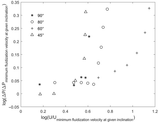
Figure 3.
Yakubov et al. re-plotted as relative pressure drop as a function of relative superficial velocity for each inclination.
Nonetheless, in both cases, it is clear that at an inclination of 45° the relative pressure drop is lower than for the other reported angles for the conditions of stable fluidization. Yakubov et al. report that the proportion of the pressure drop attributable to water friction (without a fluidized bed) was less than 4% of the total measured pressure drop.
Galvin and Dickinson [20] reported a study of the separation and transport of particles in inclined channels under centrifugal forces. They achieved centripetal forces of up to 73 g obtaining good results for particle classification. In this work, multiple narrow channels were used to obtain a synergy between the effects of high centripetal force and the inclination of the bed. However, for heat transfer, it is unlikely that such an approach would be profitable due to the great mechanical complexity that would be entailed.
Hashizume and Matsue [21] have shown that to maintain a homogeneous fluidization for vertical liquid/solid fluidized beds, the critical ratio of particle diameter to circular bed diameter is 0.220. There is very little information available on the effect of inclining the bed duct on the critical particle diameter to duct diameter or bed hydraulic diameter ratio. Chong et al. used a single particle size. Yakubov et al. used a range of particle sizes giving ratios of particle diameter to tube diameter from 0.054 to 0.124, which is well below the value of 0.2 reported by Hashizume and Matsue.
From the above literature review it can be seen that there is not a large body of research on inclined liquid/solid fluidized beds. However, that which does exist shows that an inclined liquid/solid fluidized bed allows higher superficial velocities to be achieved before particle transport occurs without resorting to active mechanical systems. Given this, it might be expected that heat transfer coefficients for surfaces in contact with these fluidized beds would be higher than for simple vertical flow. However inclined tubes would have a larger footprint within a process plant. Therefore, it was thought that wrapping the inclined channel in a circle (helical form) might be useful to reduce the flow area necessary for an inclined channel fluidized bed configuration. No studies were found which reported experimental results for such a configuration.
Pronk et al. [22] found that for stationary liquid/solid fluidized beds, the maximum fouling and scaling prevention effect was achieved with larger particles (in their case, 2 mm diameter) at the highest bed porosity consistent with homogeneous fluidization. They reported that it is believed that the impulse and energy of particle impacts at higher superficial velocities was associated with, in their case, higher particle density. Using the helical flow pattern, higher superficial velocities are also obtained with respect to a plain vertical flow regime.
Wu et al. [23], in their 2022 review of fluidized bed heat exchange technology for liquid/solid and vapour/liquid/solid systems, made no mention of geometries that cause a helical flow to enhance superficial velocities and, thus, heat transfer and self-cleaning. However, mention is made of a gas/solid spiral plate heat exchanger studied by Jiang et al. [24]. The experimental system was not an inclined helical flow but a traditional spiral plate heat exchanger with particles added to the gas flow. A maximum heat transfer enhancement of nearly 30%, with respect to a simple gas flow was reported.
It is clear that there has been considerable interest in the use of liquid/solid fluidized bed heat exchangers for heat recovery from highly fouling and scaling fluids such as geothermal brines, Tan et al. [25]. However, their economic feasibility has been hampered by their large size and thus, their cost.
2. Objectives
This experimental study sought to answer the following questions. Would there be significant changes in the fluidization behavior in a helical flow channel? Can a good quality of fluidization be established in a helical flow channel? Does this enable higher heat transfer coefficients for surfaces immersed in the bed than would be the case in a simple vertical bed? What are the pressure drop implications of this bed geometry?
3. Experimental System
Figure 4 shows the basic experimental system. Due to vertical space limitations, a means of reducing the flow stabilization tube length before the distributor was necessary. The two elbows immediately before the distributor included flow control elements based on the Cheng rotating vane [26]. A modified form was manufactured with continuous flow control channels into, through and out of the elbow assuring the 180° rotation of the flow streams around the flow axis within the elbow and the removal of the swirl at the exit (By ‘unwinding’ the flow channels). The distributor consisted of an elongated honeycomb of flow channels. The test section of the apparatus was made of a 1.87 m long transparent acrylic tube with an internal diameter of 43.8 mm. For the heat transfer experiments, a 14 mm diameter, 240 mm length, concentric bayonet ceramic electric heater from Electrothermal was used. This had an approximate heat output of 400 W (The use of a heat flux sensor makes the exact heat output unimportant).
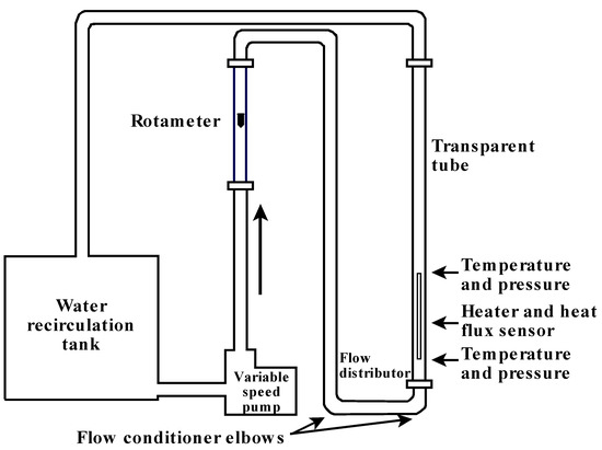
Figure 4.
Experimental system layout.
Two type T thermocouple temperature sensors were used to measure the bulk fluid temperature at the foot of the bed and immediately above the heated section. These thermocouples were Special Limits 24AWG Omega Engineering type T thermocouple wire with PTFE insulation and an error limit of 0.4% and the junctions were made using a capacitive discharge thermocouple welding system (HotSpot II Heavy Duty Welder).
Heat flux was measured at a central point along the length of the heater where thermographic imagining showed a uniform temperature field. A RdF 20457-2 micro-foil heat flux sensor (Thickness 0.127 mm, thermal impedance of 0.017 W/m2 K and 25 by 20 mm) with manufacturer’s individual calibration (Output per unit heat flux and correction for the surface temperature as measured by the integrated type T thermocouple: calibrated per ANSI MC96.1-1975 and NBS Monograph 125) was glued to the heater.
Pressure drops were measured with a differential pressure sensor from Validyne Engineering (DP15 Variable Reluctance Pressure Sensor and CD280 Multi-Channel Carrier Demodulator) which was calibrated with a dead weight calibrator (Dewitt, range 0–26 kPa and a resolution of 0.9 kPa).
The above-described sensors (Temperature, pressure and heat flux) were connected to a data logger (Omega Engineering OMB-DAQ-2416). Flow rates were measured with a rotameter (Dwyer type LFM) with a custom fabricated float which was calibrated with the weight-time method for a flow range of 0.9 to 9 m3/h. The flow rates were controlled by means of using a centrifugal pump with a variable frequency velocity control.
4. Methods
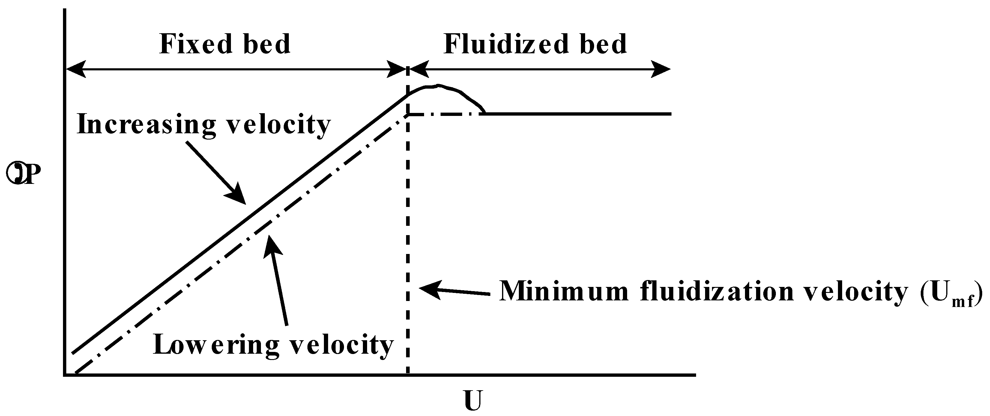
One of the basic parameters to be measured in a fluidized bed system is the minimum fluidization velocity and the concomitant pressure drop. In a vertically oriented fluidized bed with small wall effects (i.e., the bed diameter is large with respect to the particle diameter), the pressure drop tends to be almost constant from the onset of fluidization up to the point where transport of bed particles sets in. Figure 5 shows an idealized version of pressure drop vs superficial velocity for the expansion of a fluidized bed. From this, it can be observed that the simultaneous measurement of flow rate and pressure drop for rising and falling flow rate can reveal the minimum fluidization velocity.
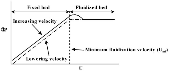
Figure 5.
Pressure drop as a function of superficial velocity for an idealized fluidized bed.
Industrial practice seldom uses spherical particles in fluidized beds; thus, several available particle forms were obtained in order to evaluate their qualitative behavior in a helical channel bed (Table 1).

Table 1.
Particle characteristics.
Figure 6 shows the bed expansion behavior of the particles as a function of Reynolds number based on the particle equivalent diameter (i.e., the diameter of a sphere of the same volume). This concurs with that reported by Richardson and Zaki [27].
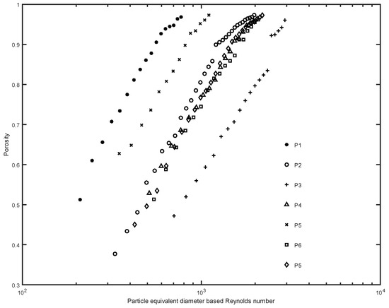
Figure 6.
Porosity as a function of particle Reynolds number for a range of particles of varying density, size and sphericity.
5. Helical Flow Apparatus
Having assured that all the particles behave in a regular fashion in a vertical bed, all were tested for the quality of fluidization in helical flow channels.
A helical flow is composed of an axial velocity and a circular or angular movement perpendicular to the axial velocity, i.e., a tangential velocity. However, the tangential velocity is not independent of the radial position in the flow field. There are several effects that influence the flow in a full helical channel or duct.
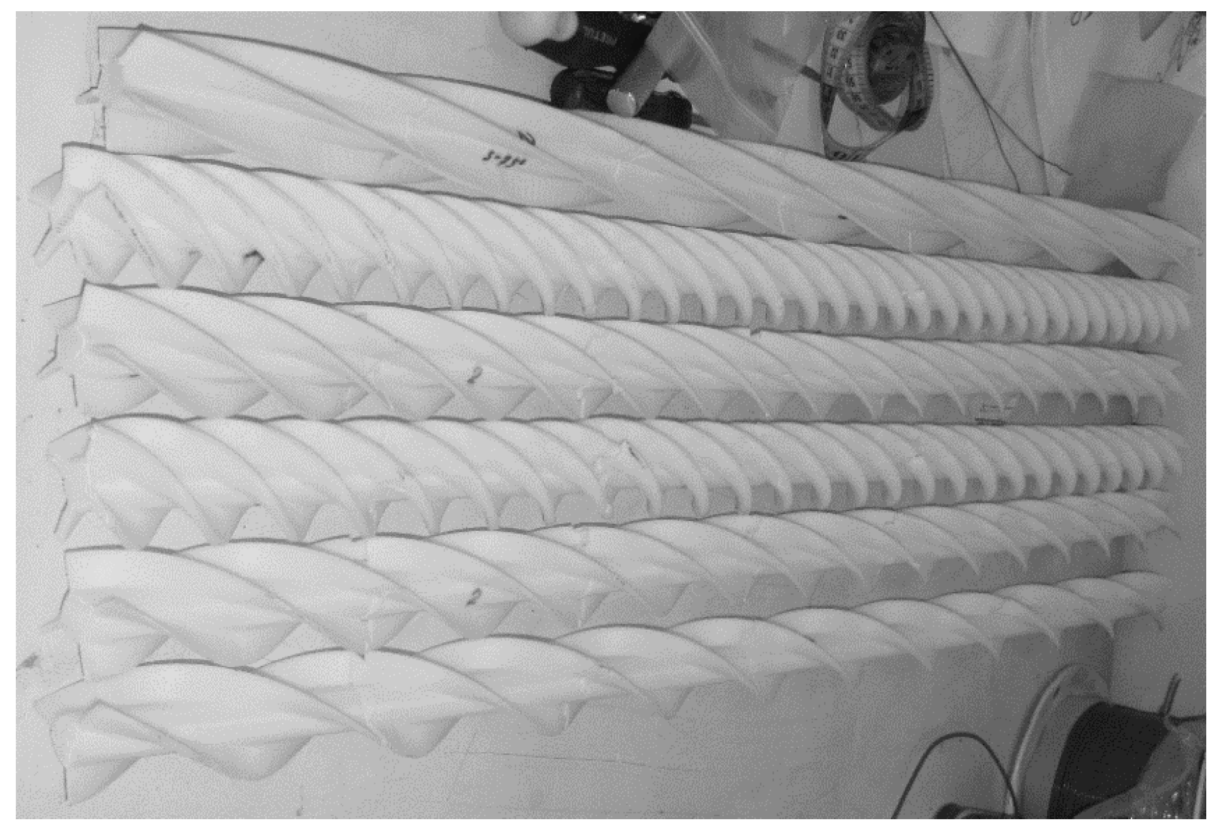
Nine helical baffle configurations were manufactured by means of fused deposition modelling with plastic. Three inclinations of the helical channels were developed, each with three different hydraulic diameters obtained by using spirals with three, four and five starts for the baffles. A selection of these baffles is shown in Figure 7.
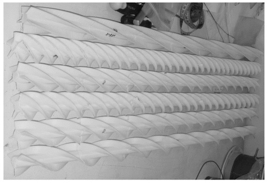
Figure 7.
Helical baffles used in the experiments.
All the particles were tested for the quality of fluidization that could be obtained with the range of helical baffle geometries.
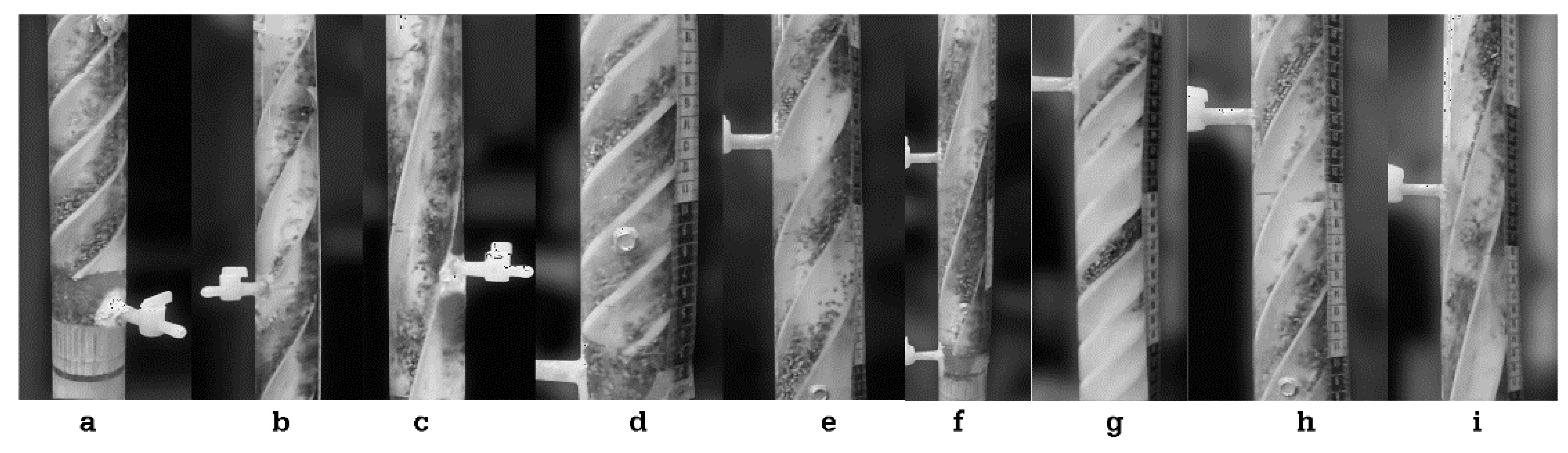
Similar effects, as mentioned above, to those that previous researchers had found in inclined liquid/solid fluidized beds were observed (Figure 8). That is: groups of particle concentrations in waves under some conditions together with particle re-circulation with the backflow in the upper part of the channel. However, under some conditions with a selected set of particles a good degree of fluidization quality was achievable. Three conditions were chosen for further study: two hydraulic diameters at 45° inclination (Figure 8a,d) and one at 60° inclination (Figure 8h). The first two correspond to baffles with three and four starts and the latter to four starts. The chopped stainless steel wire particles were chosen for further study given that they provided a good quality of fluidization and are representative of particles likely to be used in an industrial application.

Figure 8.
Examples of the quality of fluidization under inclinations of 45°, 60° and 75° and a series of hydraulic diameters achieved by using three, four and five starts for the baffles as follows: (a) 45°, three starts, (b) 60°, three starts, (c) 75°, three starts, (d) 45°, four starts, (e) 60° four starts, (f) 75°, four starts, (g) 45°, five starts, (h) 60°, five starts and (i) 75°, five starts.
A computational fluid dynamics (CFD) model using COMSOL was developed from prior work by López-Mata et al. [28] to obtain the tangential and axial velocity components (vt and va, respectively) under the experimental conditions. Models were developed of 3, 4 and 5 baffles at inclinations of 45°, 60° and 75°. Steady state incompressible flow was considered with a RANS k-ε turbulence model. The model conditions were obtained from the experimental results (Flow rates and channel geometry) and are shown in Table 2.
Table 2.
Maximum axial and tangential velocities in tested configurations as modelled in COMSOL.
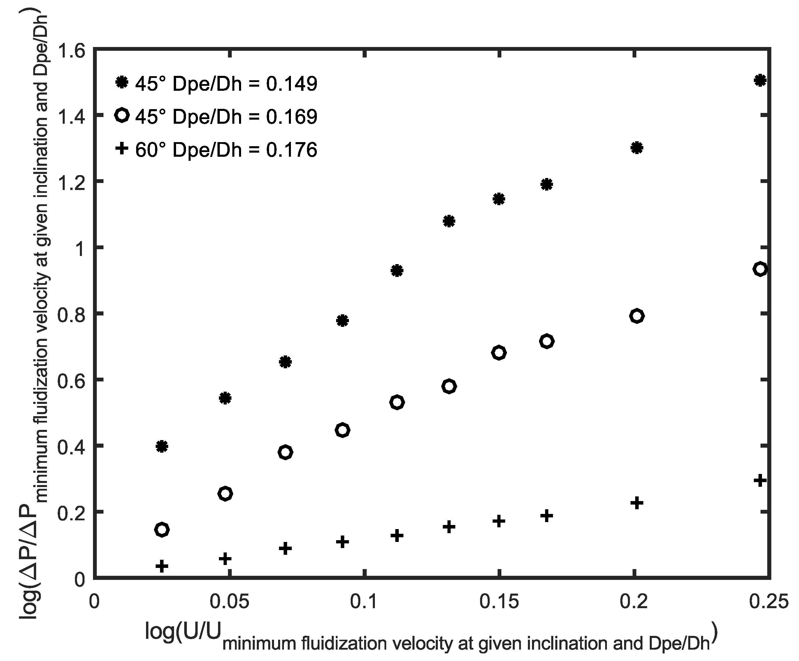
Figure 9 shows the relationship between the relative pressure drop as a function of relative fluidization velocity. These relative values are relative to the conditions at incipient fluidization for each inclination and hydraulic diameter for the three conditions further researched. The ratio of particle equivalent diameter to hydraulic diameter for these cases is well within the limit indicated from Hashizume et al. (0.2 maximum). As a comparison, for instance, image g in Figure 8; the equivalent particle diameter to hydraulic diameter ratio is 0.193, near enough to 0.2, which shows very clear evidence of bunching or slugging of particles.
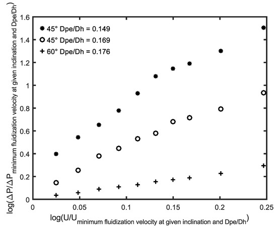
Figure 9.
Relative pressure drop as a function of relative superficial velocity under two inclinations and three hydraulic diameters for particle P# 5.
6. Heat Transfer Measurements
The heat transfer measurements were carried out with sets of baffles incorporating a central heating element as described above and shown in Figure 10.
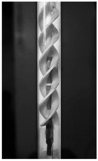
Figure 10.
Helical baffle with concentric heater.
Initially, measurements were performed over the same range of superficial flow rates as used for the fluidization of the particles (P #5) but without baffles or particles. Subsequently measurements were made with a simple vertical fluidized bed. These were used as base cases for comparison with the results from measurements with the helical baffles without and with a fluidized bed. The measurements were made after a period of 20 min to stabilize the flow and temperature conditions. The amount of heat added to the water circuit was unimportant compared to the amount of water in the circuit.
There was approximately 50 kg of water in the circuit and the heater provided 400 W power giving a temperature rise of the order of 2 K over 20 min. The measurements of heat flux, temperature of the heat flux sensor surface and the bulk water temperature at the bottom and top of the heated section allowed the direct calculation of the heat transfer coefficient.
Table 3 shows the results from the heat transfer measurements. The estimated uncertainty in the heat transfer coefficients (mostly due to the use of thermocouples as temperature sensors) has a maximum of 4.1%.
Table 3.
Results of heat transfer measurements.
7. Discussion
Fluidized beds can be improved by the use of interaction with inclined plates allowing a wider range of suspension conditions. This aids particle retention in the bed permitting higher superficial velocities and attenuates fluidization fluctuations. Forming inclined plates into a circle makes helical channels that can be fitted into a vertical tube. Dense beds can be formed with higher superficial velocities than the terminal velocity of the particles. The expansion of the bed is changed with respect to a vertical bed or even a simple inclined bed as shown by comparing Figure 2, Figure 3 and Figure 9. The differences may be a result of increased wall effects and Coriolis forces. However, the low radial velocities mean that the Coriolis forces were very low.
The use of a helical flow path allows higher velocities whilst avoiding using particle re-circulation and the consequent mechanical complications and higher probabilities of equipment breakdowns.
The measured heat transfer coefficients show substantial improvements over a stationary vertical liquid/solid fluidized bed. The best case was 49% better than the vertical bed (Table 3) but even the worst case was a 30% improvement. This case was with a type of particle that is likely to be of industrial use (chopped stainless steel wire). With larger particles, higher superficial velocities could be obtained but the channel hydraulic diameter would need to be increased. With respect to a simple concentric tube heat exchanger without a fluidized bed, the helically baffled fluidized bed can achieve an improvement of from 68 to 89%.
The cost in terms of increased pressure drop with respect to a vertical fluidized bed range from 7 to 42%, with the highest pressure drop penalty corresponding to the highest heat exchange coefficient improvement.
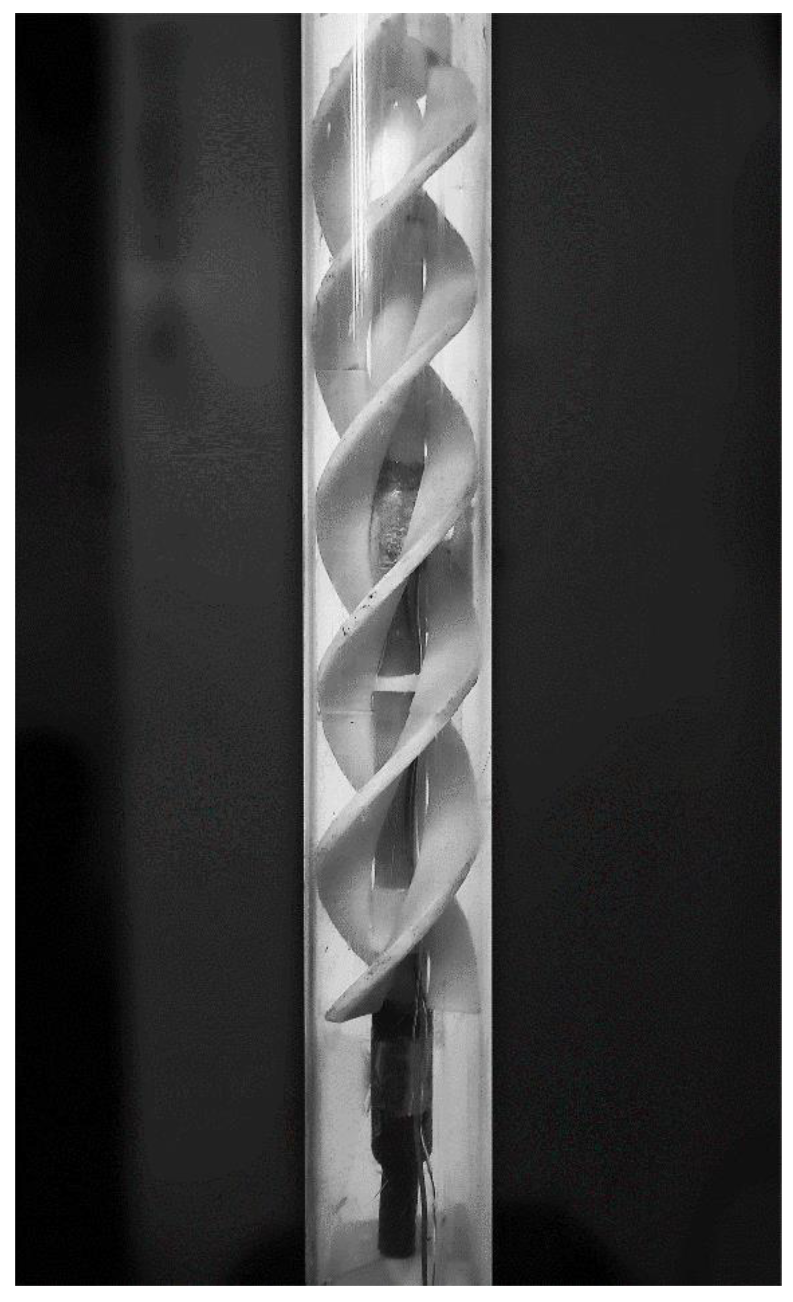
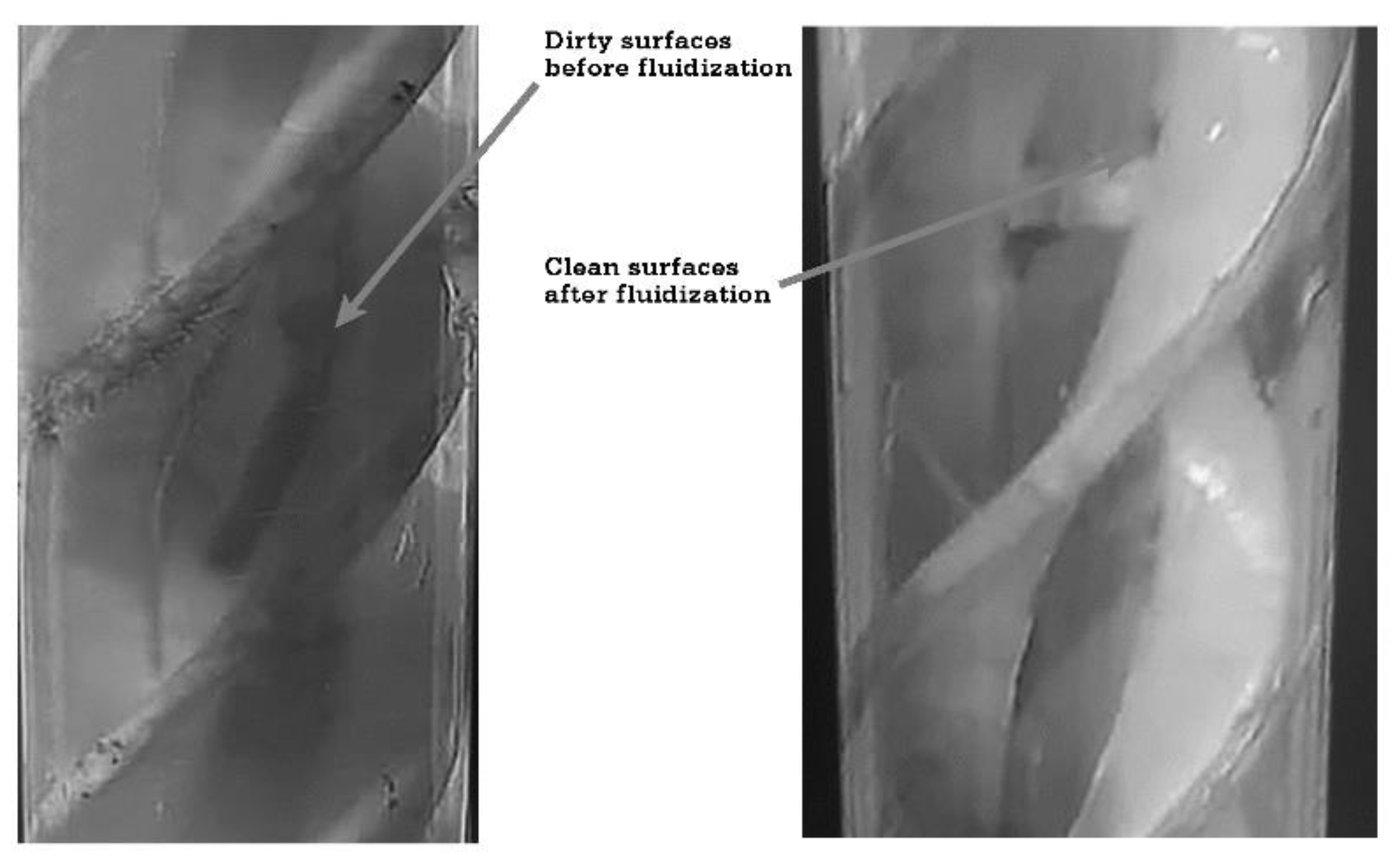
It should be noted that a simple heat exchanger will suffer performance degradation due to fouling over time, whereas a fluidized bed heat exchanger will maintain the cleanliness of the heat exchange surfaces and hence the heat transfer coefficient (Figure 11).
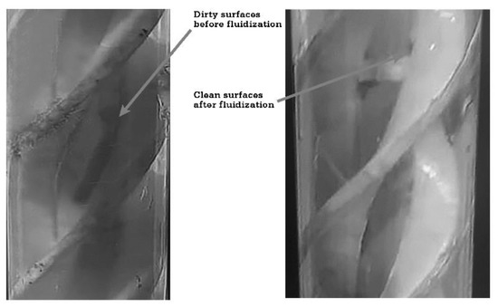
Figure 11.
Cleaning effect of fluidized bed.
8. Conclusions
With some restrictions, in terms of the ratio of equivalent particle diameter to flow channel hydraulic diameter, it is possible to establish a good quality (i.e., reasonably homogeneous) liquid/solid fluidization in a single helical channel or several helical channels in parallel.
Employing baffles to form parallel helical channels wrapped around a concentric heat source can greatly increase the heat transfer coefficient to the fluidizing medium compared with the case of no fluidized bed and no baffles and a considerably increase the heat transfer coefficients compared to a vertical fluidized bed.
The pressure drop characteristics of a helical channel fluidized bed are similar to an inclined straight bed channel, but somewhat higher. There is an absence of a pressure drop plateau. This might be attributable to wall effects and secondary flow forces such as Coriolis. This pressure drop penalty is commensurate with the improved heat transfer rates obtained.
The use of helical baffles in place of an inclined concentric tube fluidized bed heat exchanger would lower the footprint in a process plant for a given service such as, for example, cooling or heating untreated seawater or effluent.
Author Contributions
Conceptualization, O.G.-A. and C.H.; Data curation, O.G.-A.; methodology, O.G.-A., C.H. and J.J.V.-L.; software, O.G.-A. and J.J.V.-L.; formal analysis, O.G.-A. and C.H.; investigation, O.G.-A.; resources, C.H.; writing—original draft preparation, O.G.-A. and C.H.; writing—review and editing, C.H., J.J.V.-L. and F.J.S.-O.; supervision, C.H., J.J.V.-L. and F.J.S.-O.; funding acquisition, C.H. and O.G.-A. All authors have read and agreed to the published version of the manuscript.
Funding
Funding for the experimental equipment used in this work was supplied by the Apoyo a la incorporación de nuevos PTC of the Programa de Mejoramiento del Profesorado of the Secretaria de Educación Pública, Mexico (48410163); Universidad Autónoma Metropolitana, Unidad Cuajimalpa, Programa de Investigación Interdiciplinaria, convocatoria 2014 (DCNI-05-120-15), Mexico and Eficiencia Thermoe S.A. de C.V. The latter also provided laboratory space and technical support. The first author was supported by a grant for tuition fees and living expenses from the Programa Nacional de Posgrados de Calidad, Consejo Nacional de Ciencia y Tecnología, México (645426).
Informed Consent Statement
Not applicable.
Data Availability Statement
The experimental data may be requested from the first author.
Acknowledgments
The authors acknowledge the enthusiastic technical, moral and material support of Jan Pardubicky† former Director General of Eficiencia Thermoe S.A de C.V.
Conflicts of Interest
The authors declare no conflict of interest. The funders had no role in the design of the study; in the collection, analyses or interpretation of data; in the writing of the manuscript; or in the decision to publish the results.
References
- Klaren, D.G. Apparatus for Carrying out Physical and/or Chemical Processes, More Specifically a Heat Exchanger of the Continuous Type. European Patent EP0228144A1, 8 July 1987. [Google Scholar]
- Klaren, D.G. Dispositif Pour la Réalisation de Procédés Physiques et/ou Chimiques, en Particulier d’un Échangeur de Chaleur du Type Continu. European Patent EP0132873B1, 9 September 1987. [Google Scholar]
- Klaren, D.G. Appareil Pour la Mise en Oeuvre d’un Processus Physique et/ou Chimique, par Exemple un Echangeur Thermique. European Patent EP0694152B1, 13 November 1996. [Google Scholar]
- Klaren, D.G. Apparatus for Carrying out a Physical and/or Chemical Process, such as a Heat Exchanger. European Patent EP0694153B1, 13 November 1996. [Google Scholar]
- Klaren, D.G. Device for Carrying out a Physical and/or Chemical Process, such as a Heat Exchanger. Netherlands Patent NL1005517C2, 15 September 1998. [Google Scholar]
- Klaren, D.G. Device for Carrying out a Physical and/or Chemical Process, such as a Heat Exchanger. Netherlands Patent NL1005518C2, 15 September 1998. [Google Scholar]
- Klaren, D.G. Apparatus for Carrying Out a Physical and/or Chemical Process, in Particular a Heat Exchanger. WO 2016/099277 Al, 23 June 2016. [Google Scholar]
- Klaren, D.G. Apparatus and Method for Carrying out a Physical and/or Chemical Process. WO 03/069247 Al, 21 August 2003. [Google Scholar]
- Demircan, N.; Gibbs, B.M.; Swithenbank, J.; Taylor, D.S. Rotating fluidised bed combustor, Fluidization. In Proceedings of the Second Engineering Foundation Conference, Trinty College, Cambridge, UK, 2–6 April 1978; Davidson, J.F., Keairns, D.L., Eds.; pp. 270–275. [Google Scholar]
- Margraf, J.; Werther, J. Fluid mechanics of liquid–solid fluidization in the centrifugal field. Can. J. Chem. Eng. 2008, 86, 276–287. [Google Scholar] [CrossRef]
- Margraf, J.; Werter, J. Continuous classification in a centrifugal fluidized bed apparatus. J. Taiwan Inst. Chem. Eng. 2009, 40, 669–681. [Google Scholar] [CrossRef]
- O’Dea, D.P.; Rudolph, V.; Chong, Y.O.; Leung, L.S. The effect of inclination on fluidized beds. Powder Technol. 1990, 63, 169–178. [Google Scholar] [CrossRef]
- Zabrodsky, S.S. Hydrodynamics and Heat Transfer in Fluidized Beds; Zenz, F.A., Translator; The MIT Press: Cambridge, MA, USA, 1966. [Google Scholar]
- Galvin, K.P.; Nguyentranlam, G. Influence of parallel inclined plates in a liquid fluidized bed system. Chem. Eng. Sci. 2002, 57, 1231–1234. [Google Scholar] [CrossRef]
- Hudson, C.; Briens, C.L.; Prakash, A. Effect of inclination on liquid-solid fluidized beds. Powder Technol. 1996, 89, 101–113. [Google Scholar] [CrossRef]
- Yakubov, B.; Tanny, J.; Maron, D.M.; Brauner, N. The dynamics and structure of a liquid–solid fluidized bed in inclined pipes. Chem. Eng. J. 2007, 128, 105–114. [Google Scholar] [CrossRef]
- Murata, H.; Oka, H.; Adachi, M.; Harumi, K. Effects of the ship motion on gas–solid flow and heat transfer in a circulating fluidized bed. Powder Technol. 2012, 231, 7–17, Corrected on Powder Technol. 2014, 254, 114. [Google Scholar] [CrossRef]
- Ramesh, K.V.; Chandra, K.S.; Kumar, K.A. Flow Regime Mapping of Liquid-Solid Inclined Fluidized Beds. Int. J. Eng. Appl. Sci. 2016, 3, 56–57. [Google Scholar] [CrossRef]
- Chong, Y.O.; Leung, L.S.; Nguyen, T.H.; Teo, C.S. Inclined Fluidized Bed; InAIChE Symp. Ser. Department of Chemical Engineering, University of Queensland: St. Lucia, QLD, Australia, 1984; Volume 80, pp. 149–155. [Google Scholar]
- Galvin, K.P.; Dickenson, J.E. Particle transport and separation in inclined channels subject to centrifugal forces. Chem. Eng. Sci. 2013, 87, 294–305. [Google Scholar] [CrossRef]
- Hashizume, K.; Matsue, T. Heat Transfer in Liquid-Fluidized Beds Affected by Column Wall. Heat Transf.-Asian Res. 2000, 29, 598–608. [Google Scholar] [CrossRef]
- Pronk, P.; Ferreira, C.A.I.; Witkamp, G.J. Prevention of fouling and scaling in stationary and circulating liquid–solid fluidized bed heat exchangers: Particle impact measurements and analysis. Int. J. Heat Mass Transf. 2009, 52, 3857–3868. [Google Scholar] [CrossRef]
- Wu, C.; Yang, H.; He, X.; Hu, C.; Yang, L.; Li, H. Principle, development, application design and prospect of fluidized bed heat exchange technology: Comprehensive review. Renew. Sustain. Energy Rev. 2022, 157, 112023. [Google Scholar] [CrossRef]
- Jiang, F.; Dong, X.; Qi, G.; Mao, P.; Wang, J.; Li, X. Heat-transfer performance and pressure drop in a gas-solid circulating fluidized bed spiral-plate heat exchanger. Appl. Therm. Eng. 2020, 171, 115091. [Google Scholar] [CrossRef]
- Tan, M.; Karabacak, R.; Acar, M. Experimental assessment the liquid/solid fluidized bed heat exchanger of thermal performance: An application. Geothermics 2016, 62, 70–78. [Google Scholar] [CrossRef]
- Mattingly, G.E.; Yeh, T.T. NIST Special Tests of the Pipe Flows Produced by the Cheng Rotating Vane in Two Selected Elbow Configurations. Available online: http://www.chengfluid.com/yahoo_site_admin1/assets/docs/NIST_CRV_Special_Flow_Test_Report.142144451.pdf (accessed on 8 July 2021).
- Richardson, J.F.; Zaki, W.N. Sedimentation and fluidization, Part I. Trans. I Chem. Eng. 1954, 32, S83–S100. [Google Scholar]
- López Mata, F.A.; Heard, C.; García Aranda, O.; Valencia López, J.J. Simulación en 2D de la hidrodinámica de una columna de lechos fluidizados. In Proceedings of the Memorias del XXXVII Encuentro Nacional de la AMIDIQ, Puerto Vallarta, Mexico, 3–6 May 2016; pp. PRO-132–PRO-137. [Google Scholar]


Publisher’s Note: MDPI stays neutral with regard to jurisdictional claims in published maps and institutional affiliations. |
© 2022 by the authors. Licensee MDPI, Basel, Switzerland. This article is an open access article distributed under the terms and conditions of the Creative Commons Attribution (CC BY) license (https://creativecommons.org/licenses/by/4.0/).