
Enhanced Virtual Inertia Control for Microgrids with High-Penetration Renewables Based on Whale Optimization


Abstract
1. Introduction
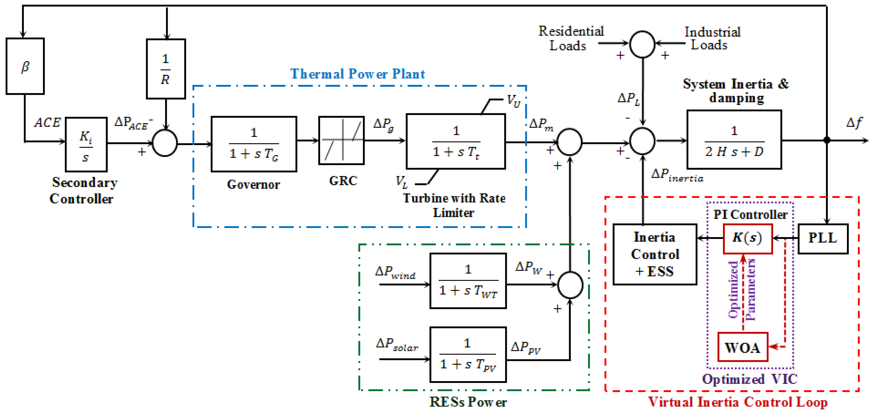
2. System Modeling
2.1. A. Structure of the Studied Microgrid
2.2. B. Structure of the Understudy Microgrid
3. Dynamic Modeling of the Studied Microgrid
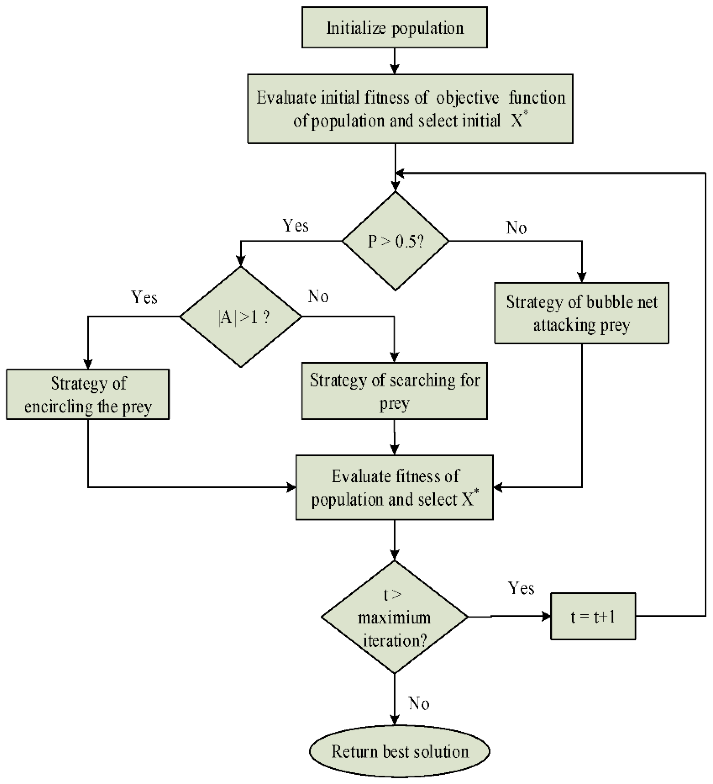
4. Modeling of Whale Optimization Algorithm (WOA)
4.1. A. Exploration Phase: Modeling of Searching
4.2. B. Modeling of Encircling
4.3. C. Exploitation Phase: Modeling of Bubble-Net Strategy
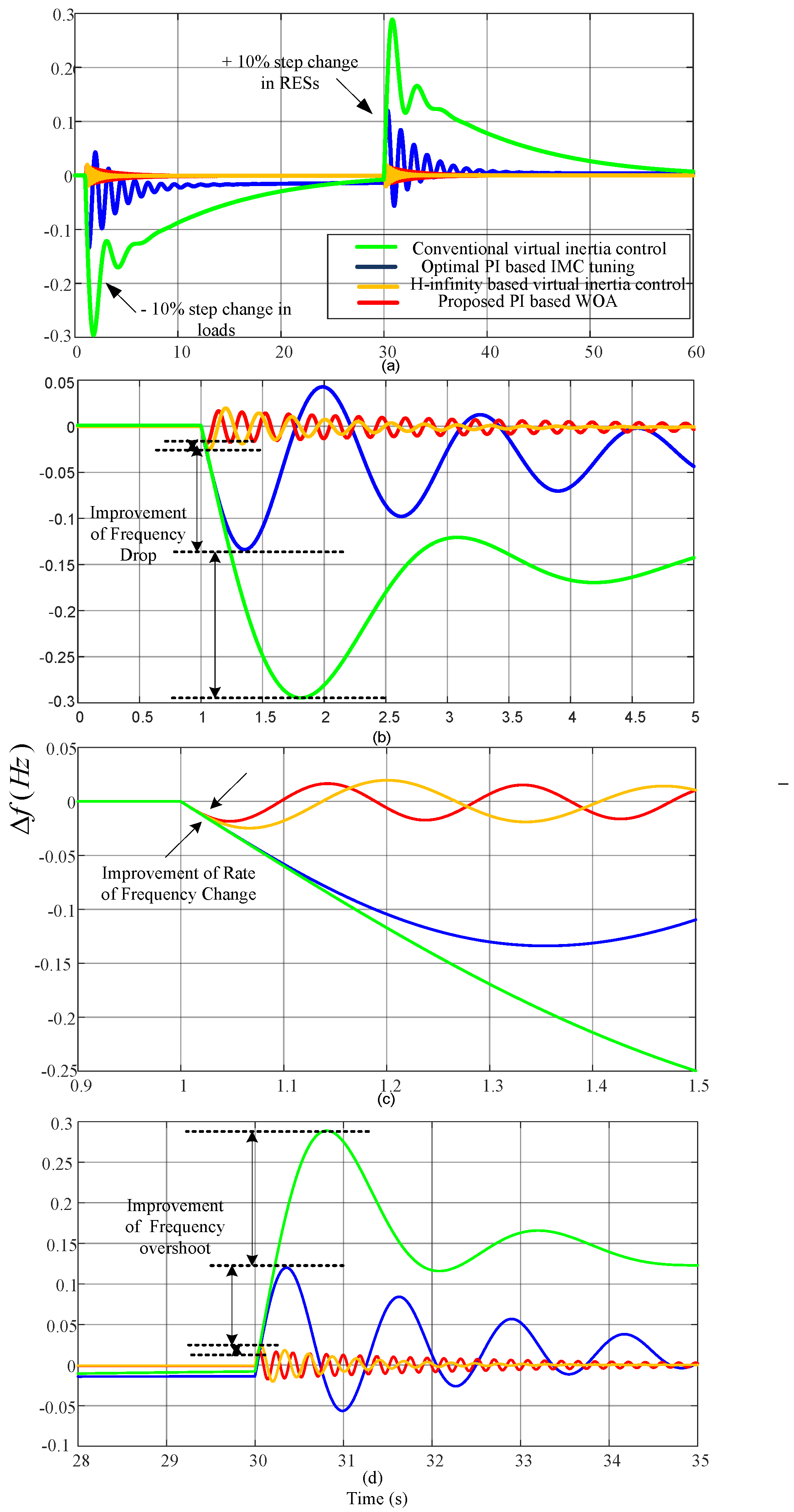
5. Results and Discussion
5.1. Scenario 1
5.2. Scenario 2
5.3. Scenario 3
5.4. Scenario 4
6. Conclusions
Author Contributions
Funding
Conflicts of Interest
References
- Kerdphol, T.; Rahman, F.S.; Watanabe, M.; Mitani, Y.; Turschner, D.; Beck, H.P. Enhanced Virtual Inertia Control Based on Derivative Technique to Emulate Simultaneous Inertia and Damping Properties for Microgrid Frequency Regulation. IEEE Access 2019, 7, 14422–14433. [Google Scholar] [CrossRef]
- Abdel-Rahim, O.; Chub, A.; Vinnikov, D.; Blinov, A. DC Integration of Residential Photovoltaic Systems: A Survey. IEEE Access 2022, 10, 66974–66991. [Google Scholar] [CrossRef]
- Kerdphol, T.; Watanabe, M.; Mitani, Y.; Phunpeng, V. Applying virtual inertia control topology to SMES system for frequency stability improvement of low-inertia microgrids driven by high renewables. Energies 2019, 12, 3902. [Google Scholar] [CrossRef]
- Abdel-Rahim, O.; Funato, H. Droop Method Based on Model Predictive Control for DC Microgrid. In Proceedings of the 19th International Conference on Electrical Machines and Systems, Chiba, Japan, 13–16 November 2016; pp. 1–6. [Google Scholar]
- Kerdphol, T.; Watanabe, M.; Hongesombut, K.; Mitani, Y. Self-Adaptive Virtual Inertia Control-Based Fuzzy Logic to Improve Frequency Stability of Microgrid with High Renewable Penetration. IEEE Access 2019, 7, 76071–76083. [Google Scholar] [CrossRef]
- Kerdphol, T.; Rahman, F.S.; Mitani, Y. Virtual inertia control application to enhance frequency stability of interconnected power systems with high renewable energy penetration. Energies 2018, 11, 981. [Google Scholar] [CrossRef]
- ENTSO-E. Frequency Stability Evaluation Criteria for the Synchronous Zone of Continental Europe–Requirements and Impacting Factors; ENTSO-e Publ.: Brussels, Belgium, 2016; p. 25. Available online: https://docstore.entsoe.eu/Documents/SOCdocuments/RGCE_SPD_frequency_stability_criteria_v10.pdf (accessed on 5 June 2022).
- Kerdphol, T.; Rahman, F.S.; Watanabe, M.; Mitani, Y. Robust Virtual Inertia Control of a Low Inertia Microgrid Considering Frequency Measurement Effects. IEEE Access 2019, 7, 57550–57560. [Google Scholar] [CrossRef]
- Zhao, J.; Lyu, X.; Fu, Y.; Hu, X.; Li, F. Coordinated Microgrid Frequency Regulation Based on DFIG Variable Coefficient Using Virtual Inertia and Primary Frequency Control. IEEE Trans. Energy Convers. 2016, 31, 833–845. [Google Scholar] [CrossRef]
- Castro Martinez, J.; Arnaltes, S.; Alonso-Martinez, J.; Rodriguez Amenedo, J.L. Contribution of Wind Farms to the Stability of Power Systems with High Penetration of Renewables. Energies 2021, 14, 2207. [Google Scholar] [CrossRef]
- Parise, G.; Martirano, L.; Kermani, M.; Kermani, M. Designing a power control strategy in a microgrid using PID/fuzzy controller based on battery energy storage. In Proceedings of the 2017 IEEE International Conference on Environment and Electrical Engineering and 2017 IEEE Industrial and Commercial Power Systems Europe (EEEIC/I&CPS Europe), Milan, Italy, 6–9 June 2017; pp. 1–5. [Google Scholar] [CrossRef]
- Sayed, F.; Kamel, S.; Abdel-Rahim, O. Load Shedding Solution Using Multi-Objective Teaching-Learning-Based Optimization. In Proceedings of the International Conference on Innovation Trends in Computer Engineering, Aswan, Egypt, 19–21 February 2018; pp. 447–452. [Google Scholar]
- Bevrani, H.; Habibi, F.; Babahajyani, P.; Watanabe, M.; Mitani, Y. Intelligent frequency control in an AC microgrid: Online PSO-based fuzzy tuning approach. IEEE Trans. Smart Grid 2012, 3, 1935–1944. [Google Scholar] [CrossRef]
- Gong, K.; Shi, J.; Liu, Y.; Wang, Z.; Ren, L.; Zhang, Y. Application of SMES in the Microgrid Based on Fuzzy Control. IEEE Trans. Appl. Supercond. 2016, 26, 1–5. [Google Scholar] [CrossRef]
- Kamel, S.; Rabea, F.; Jurado, F.; Abdel-Rahim, O. Implementation of a Simplified SVC Model into Newton-Raphson Load Flow Algorithm. In Proceedings of the International Conference on Innovation Trends in Computer Engineering, Aswan, Egypt, 19–21 February 2018; pp. 374–437. [Google Scholar]
- Mohamed, E.A.; Mitani, Y. Enhancement the Dynamic Performance of Islanded Microgrid Using a Coordination of Frequency Control and Digital Protection. Int. J. Emerg. Electr. Power Syst. 2019, 20, 1–15. [Google Scholar] [CrossRef]
- Sedghi, L.; Fakharian, A. Voltage and frequency control of an islanded microgrid through robust control method and fuzzy droop technique. In Proceedings of the 2017 5th Iranian Joint Congress on Fuzzy and Intelligent Systems (CFIS), Qazvin, Iran, 7–9 March 2017; pp. 110–115. [Google Scholar] [CrossRef]
- Rakhshani, E.; Remon, D.; Cantarellas, A.M.; Garcia, J.M.; Rodriguez, P. Virtual Synchronous Power Strategy for Multiple HVDC Interconnections of Multi-Area AGC Power Systems. IEEE Trans. Power Syst. 2017, 32, 1665–1677. [Google Scholar] [CrossRef]
- Rakhshani, E.; Remon, D.; Cantarellas, A.M.; Rodriguez, P. Analysis of derivative control based virtual inertia in multi-area high-voltage direct current interconnected power systems. IET Gener. Transm. Distrib. 2016, 10, 1458–1469. [Google Scholar] [CrossRef]
- Chen, Y.; Hesse, R.; Turschner, D.; Beck, H.P. Improving the grid power quality using virtual synchronous machines. In Proceedings of the 2011 International Conference on Power Engineering, Energy and Electrical Drives, Torremolinos, Spain, 11–13 May 2011; pp. 1–6. [Google Scholar] [CrossRef]
- Rakhshani, E.; Rodriguez, P. Inertia Emulation in AC/DC Interconnected Power Systems Using Derivative Technique Considering Frequency Measurement Effects. IEEE Trans. Power Syst. 2017, 32, 3338–3351. [Google Scholar] [CrossRef]
- Kerdphol, T.; Rahman, F.S.; Mitani, Y.; Watanabe, M.; Kufeoglu, S. Robust Virtual Inertia Control of an Islanded Microgrid Considering High Penetration of Renewable Energy. IEEE Access 2018, 6, 625–636. [Google Scholar] [CrossRef]
- Liu, J.; Miura, Y.; Ise, T. Comparison of Dynamic Characteristics between Virtual Synchronous Generator and Droop Control in Inverter-Based Distributed Generators. IEEE Trans. Power Electron. 2016, 31, 3600–3611. [Google Scholar] [CrossRef]
- Alipoor, J.; Miura, Y.; Ise, T. Stability assessment and optimization methods for microgrid with multiple VSG units. IEEE Trans. Smart Grid 2018, 9, 1462–1471. [Google Scholar] [CrossRef]
- Wu, H.; Ruan, X.; Yang, D.; Chen, X.; Zhao, W.; Lv, Z.; Zhong, Q.-C. Small-Signal Modeling and Parameters Design for Virtual Synchronous Generators. IEEE Trans. Ind. Electron. 2016, 63, 4292–4303. [Google Scholar] [CrossRef]
- Alhejaj, S.M.; Gonzalez-Longatt, F.M. Impact of inertia emulation control of grid-scale BESS on power system frequency response. In Proceedings of the 2016 International Conference for Students on Applied Engineering (ICSAE), Newcastle Upon Tyne, UK, 20–21 October 2016; pp. 254–258. [Google Scholar] [CrossRef]
- Fang, J.; Zhang, R.; Li, H.; Tang, Y. Frequency Derivative-based Inertia Enhancement by Grid-Connected Power Converters with a Frequency-Locked-Loop. IEEE Trans. Smart Grid 2018, 10, 4918–4927. [Google Scholar] [CrossRef]
- Oshnoei, S.; Aghamohammadi, M.; Oshnoei, S.; Oshnoei, A.; Mohammadi-Ivatloo, B. Provision of Frequency Stability of an Islanded Microgrid Using a Novel Virtual Inertia Control and a Fractional Order Cascade Controller. Energies 2021, 14, 4152. [Google Scholar] [CrossRef]
- Bevrani, H.; Ise, T.; Miura, Y. Virtual synchronous generators: A survey and new perspectives. Int. J. Electr. Power Energy Syst. 2014, 54, 244–254. [Google Scholar] [CrossRef]
- Teodorescu, R.; Liserre, M.; Rodriguez, P. Grid Converters for Photovoltaic and Wind Power Systems; Wiley: Sussex, UK, 2011. [Google Scholar]
- Orihara, D.; Kikusato, H.; Hashimoto, J.; Otani, K.; Takamatsu, T.; Oozeki, T.; Taoka, H.; Matsuura, T.; Miyazaki, S.; Hamada, H.; et al. Contribution of Voltage Support Function to Virtual Inertia Control Performance of Inverter-Based Resource in Frequency Stability. Energies 2021, 14, 4220. [Google Scholar] [CrossRef]
- Fathi, A.; Shafiee, Q.; Bevrani, H. Robust frequency control of microgrids using an extended virtual synchronous generator. IEEE Trans. Power Syst. 2018, 33, 6289–6297. [Google Scholar] [CrossRef]
- Nasiri, J.; Khiyabani, F.M. A whale optimization algorithm (WOA) approach for clustering. Cogent Math. Stat. 2018, 5, 1483565. [Google Scholar] [CrossRef]
- Zhou, Y.; Ling, Y.; Luo, Q. Levy flight trajectory-based whale optimization algorithm for global optimization. IEEE Access 2017, 5, 6168–6186. [Google Scholar] [CrossRef]
- Mehne, H.H.; Mirjalili, S. A parallel numerical method for solving optimal control problems based on whale optimization algorithm. Knowl.-Based Syst. 2018, 151, 114–123. [Google Scholar] [CrossRef]
- Mirjalili, S.; Lewis, A. The Whale Optimization Algorithm. Adv. Eng. Softw. 2016, 95, 51–67. [Google Scholar] [CrossRef]
- Rana, N.; Latiff, M.S.A.; Abdulhamid, S.M.; Chiroma, H. Whale Optimization Algorithm: A Systematic Review of Contemporary Applications, Modifications and Developments; Springer: London, UK, 2020; Volume 32. [Google Scholar] [CrossRef]
- Bevrani, H.; Francois, B.; Ise, T. Microgrid Dynamics and Control; John Wiley & Sons: Hoboken, NJ, USA, 2017. [Google Scholar] [CrossRef]
- Kaveh, A.; Farhoudi, N. A new optimization method: Dolphin echolocation. Adv. Eng. Softw. 2013, 59, 53–70. [Google Scholar] [CrossRef]


| Parameter | Nominal Value |
|---|---|
| Frequency bias factor, (p.u.MW/Hz) | 1 |
| Secondary frequency controller, (s) | 0.05 |
| Time constant of the governor, (s) | 0.1 |
| Time constant of turbine, (s) | 0.4 |
| Droop characteristic, (Hz/p.u.MW) | 2.4 |
| System damping, (p.u.MW/Hz) | 0.015 |
| System inertia, (p.u.MW/s) | 0.083 |
| Virtual inertia control gain, (s) | 0.8 |
| Time constant of wind turbine, (s) | 1.5 |
| Time constant of solar system, (s) | 1.85 |
| Natural frequency, (rad/s) | 1.5 |
| The damping ratio, | 1.414 |
| Time constant of virtual inertia, (s) | 10 |
| Time constant of PLL, (s) | 0.943 |
| The phase-detector control gain, | 1 |
| The loop filter control gain, | 2.12 |
| The gain of the voltage-controlled oscillator, | 1 |
| PARAMETER | VALUE |
|---|---|
| Maximum iterations | 300 |
| Search agent size | 10 |
| Problem dimension | 2 |
| Range of the proportional parameter | [−100, 2000] |
| Range of the integral parameter | [−100, 500] |
| PARAMETER | ||
|---|---|---|
| Value | 1.073 × 10³ | 141.279 |
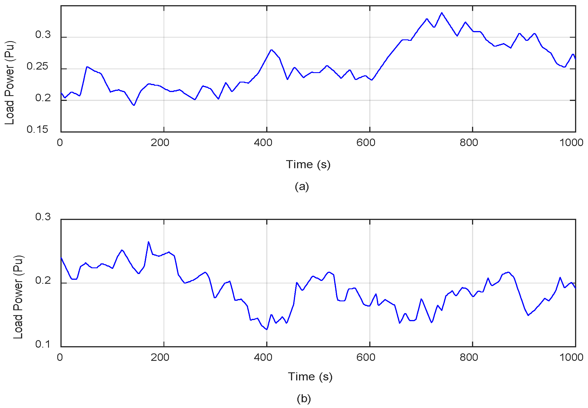
| RESs/Load Type | Starting Time | Stop Time |
|---|---|---|
| Solar generation | Initial | 800 s |
| Wind generation | 200 s | - |
| Residential load | Initial | - |
| Industrial load | Initial | - |
Publisher’s Note: MDPI stays neutral with regard to jurisdictional claims in published maps and institutional affiliations. |
© 2022 by the authors. Licensee MDPI, Basel, Switzerland. This article is an open access article distributed under the terms and conditions of the Creative Commons Attribution (CC BY) license (https://creativecommons.org/licenses/by/4.0/).
Share and Cite
Faragalla, A.; Abdel-Rahim, O.; Orabi, M.; Abdelhameed, E.H. Enhanced Virtual Inertia Control for Microgrids with High-Penetration Renewables Based on Whale Optimization. Energies 2022, 15, 9254. https://doi.org/10.3390/en15239254
Faragalla A, Abdel-Rahim O, Orabi M, Abdelhameed EH. Enhanced Virtual Inertia Control for Microgrids with High-Penetration Renewables Based on Whale Optimization. Energies. 2022; 15(23):9254. https://doi.org/10.3390/en15239254
Chicago/Turabian StyleFaragalla, Asmaa, Omar Abdel-Rahim, Mohamed Orabi, and Esam H. Abdelhameed. 2022. "Enhanced Virtual Inertia Control for Microgrids with High-Penetration Renewables Based on Whale Optimization" Energies 15, no. 23: 9254. https://doi.org/10.3390/en15239254
APA StyleFaragalla, A., Abdel-Rahim, O., Orabi, M., & Abdelhameed, E. H. (2022). Enhanced Virtual Inertia Control for Microgrids with High-Penetration Renewables Based on Whale Optimization. Energies, 15(23), 9254. https://doi.org/10.3390/en15239254