Article

Thermal Performance of Load-Bearing, Lightweight, Steel-Framed Partition Walls Using Thermal Break Strips: A Parametric Study

ISISE, Department of Civil Engineering, University of Coimbra, 3030-788 Coimbra, Portugal
*
Author to whom correspondence should be addressed.
Energies 2022, 15(24), 9271; https://doi.org/10.3390/en15249271
Submission received: 2 November 2022 / Revised: 29 November 2022 / Accepted: 4 December 2022 / Published: 7 December 2022
(This article belongs to the Special Issue Smart Materials and Devices for Energy Saving and Harvesting)

Abstract

:
Thermal bridges are a very relevant issue for lightweight steel-framed (LSF) construction systems given the high thermal conductivity of steel, which can negatively compromise their thermal behaviour, reduce their durability, and decrease the building energy efficiency. Several thermal bridge mitigation strategies exist, including the attachment of thermal break strips (TBS) to the steel studs’ flanges as one of the most widely employed techniques. In this research, the relevance of TBS to the thermal performance improvement of load-bearing LSF partition walls was assessed by performing a parametric study, making use of a validated 2D numerical model. A sensitivity analysis was performed for five different key parameters, and their importance was evaluated. The assessed parameters included the number of TBS and their thickness, width, and thermal conductivity, as well as the vertical steel stud spacing. We found that these parameters were all relevant. Moreover, regardless of the TBS thermal conductivity, it is always worth increasing their thickness. However, the increase in the TBS width does not always lead to increased thermal resistance; a thermal performance reduction was noted when increasing the width of the TBS at higher thermal conductivities. Therefore, it was concluded that it is more efficient to increase TBS thickness than their width.

1. Introduction

One of the activity sectors with higher energy consumption is the building sector, which is responsible for 40% of consumption and 36% of the emissions of greenhouse gases in the European Union (EU) [1]. Globally, the values for this industry are 36% and 37% [2], respectively. In the last 2 years, there was a decline in both of these values due to the COVID-19 pandemic [2]. The energy consumed in the EU for space heating and cooling corresponds to 50% of the total, of which 80% is used in buildings [3]. Therefore, the EU promotes the use of renewable energy for heating and cooling [4], as well as renovation of building stock, prioritizing energy efficiency to achieve the EU’s energy and climate goals [3]. In the EU, 75% of the building stock is not energy efficient; thus, the renovation of existing buildings could reduce total energy consumption by 5–6% [1], corresponding to a reduction in gas imports of 13–15.6% [3].
The construction sector has been adapting and changing to further industrialized and lightweight substitutes. The light steel-framed (LSF) system is one of these alternatives, which has been proliferating given its remarkable advantages relative to traditional heavyweight brick masonry and reinforced concrete systems. These advantages include [5,6,7]: easier handling and transportation, given the very reduced weight; high mechanical strength; suitability for prefabrication, ensuring improved quality-control of building elements; adequacy for modular construction; time savings resulting from a faster construction process onsite; high potential for reuse and recyclability (greater than 95%), representing more sustainable construction; excellent stability of dimensions and shape in contact with moisture; decrease in waste; water consumption reduction (dry construction); and reduced need for an intensive workforce and heavy machinery.
However, the LSF system, when not well designed, given the high thermal conductivity of the steel structure, is disposed to forming thermal bridges, which may lead to a thermally inefficient building envelope with condensation problems and thermal discomfort of the occupants [8].
Thermal bridges in buildings can be caused by materials with high thermal conductivity (e.g., steel studs) trespassing layers with high thermal resistance (e.g., batt insulation) within the assemblies [9], or due to junctions, such as connections between the wall and wall, wall and roof, or wall and floor [10]. Thermal bridges decrease the energy efficiency of buildings, impacting the heating and cooling energy needs by up to 30% [11] and 20% [10], respectively. Several studies have been undertaken on reinforced concrete and brick masonry walls. Al-Sanea and Zedan [12] verified that mortar joints, corresponding to 9.1% of the total wall area, reduce the R-value by 51% and increase the transmission load by 103%. The energy consumption increase due to existing thermal bridges of representative wall configurations used in Greece was shown to be up to 35% more than estimated during the design stage, as shown by Theodosiou and Papadopoulos [13]. Hua Ge and Baba [10] verified that thermal bridges would increase the annual heating load by 30% and 18% for hot climates and cold climates, respectively. The effect of thermal bridges on buildings was also studied by Jedidi and Benjeddou [14], who concluded that to minimize the problems from thermal bridges, insulation placement on the outside was the preferable option, decreasing the risk of condensation, mould growth, and heat loss.
Due to steel’s high thermal conductivity, the importance of thermal bridges in LSF structures can be even greater [15], making this issue an important topic for many researchers in diverse fields, such as parametric studies [8,16,17]; development of measurement methods [18,19]; analytical assessment methodology [20]; experimental methods [21,22,23]; and numerical simulations [23,24].
Some thermal bridge mitigation strategies have been studied for LSF buildings, such as the use of external thermal insulation composite systems (ETICS) [8,16,25,26]; the use of TBS [16,17,21,22,23]; the use of steel stud flanges’ indentation [17]; and the use of slotted steel studs [16,27]. However, regarding the use of TBS, a systematic study of relevant related parameters (e.g., TBS cross-section dimensions and material thermal conductivities) to enhance the thermal performance of load-bearing partition LSF walls was absent within the existing literature.
Each thermal bridge mitigation strategy has its intrinsic advantages and/or drawbacks. The use of ETICS is very common, with their main advantage being reduced LSF wall thickness, as the extra ETICS thickness can be located outside the floor area and does not compromise the net floor area [26]. The use of TBS has the main advantage of very cost-effective material use, as these strips are placed in a very localized way (along the studs’ flanges) and the small amount of material is located where it is most needed, i.e., along the steel frame [21]. One possible drawback is the reduced mechanical resistance to shear actions due to lateral loading [28], because the sheathing panels are now further way from the steel frame. The use of steel stud flanges with an indentation to decrease the contact area between the steel and the sheeting panels has the main advantage of not increasing the LSF thickness, and it is also possible to fill the original flange gap with insulation material [17]. The main drawback of the slotted steel studs is their consequent load-bearing capacity reduction [16].
In this paper, the thermal performance enhancement achieved by the use of TBS on load-bearing partition LSF walls was evaluated. A parametric study was performed where two steel stud spacings were evaluated (400 and 600 mm), two TBS positions were considered (on the exterior steel stud flange and on both flanges), and five thermal conductivities of the TBS material (ranging from 7.5 up to 120 mW/m/K) were assessed. Moreover, regarding the TBS cross-section geometry, five thicknesses (ranging from 5 up to 15 mm) and five widths (ranging from 30 up to 70 mm) were studied. These LSF wall configurations corresponded to 202 numerical models that were evaluated in this parametric study. These numerical models were successfully validated experimentally, and their accuracy was also verified by comparing the results with the ISO 10211 test cases, the ISO 6946 analytical approach, and a three-dimensional finite element model.
Following this short introduction, in the next section (Materials and Methods), the assessed load-bearing partition LSF walls are presented, starting with a description of the reference LSF wall, followed by the parameters evaluated within this parametric study, and characterization of the materials and the numerical simulations carried out. After this, the results are shown and discussed for the evaluated parameters. Finally, the main conclusions of the work are presented.

2. Materials and Methods

In this section, the LSF walls are detailed, starting with the reference. Moreover, the parameters of this study are defined, and the geometry of the assessed TBS—namely their thickness and width—is also presented. This is followed by the characterization of the materials used in this research in relation to their thermal conductivities. Next, the numerical simulations carried out in this study are explained, including the discretization of the evaluated domain, boundary conditions, and verification of the model accuracy and its validation.

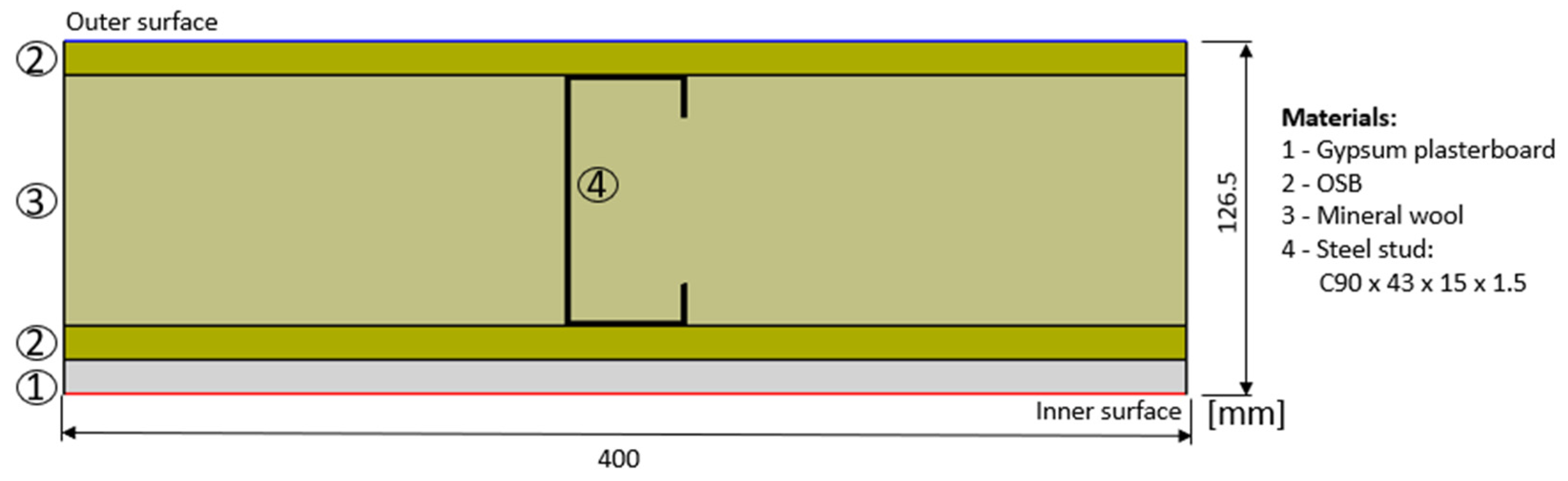
2.1. Reference Partition LSF Wall

In this parametric study, a load-bearing LSF partition wall was assumed as a reference. Its cross-section is displayed in Figure 1. All evaluated LSF walls were made with commercial C90 × 43 × 15 × 1.5 cold-formed steel studs with the following dimensions: web (90 mm), flange (43 mm), lip return (15 mm), and steel sheet thickness (1.5 mm). Figure 1 shows the cross-section of a typical partition, used here as a reference LSF wall. There was a 90 mm thick batt insulation made with mineral wool (MW) filling the wall cavity. A 12 mm thick oriented strand board (OSB) structural sheathing panel was placed on both sides of the vertical steel studs. Moreover, there was an additional inner sheathing layer made with gypsum plasterboard (GPB), with a thickness of 12.5 mm.

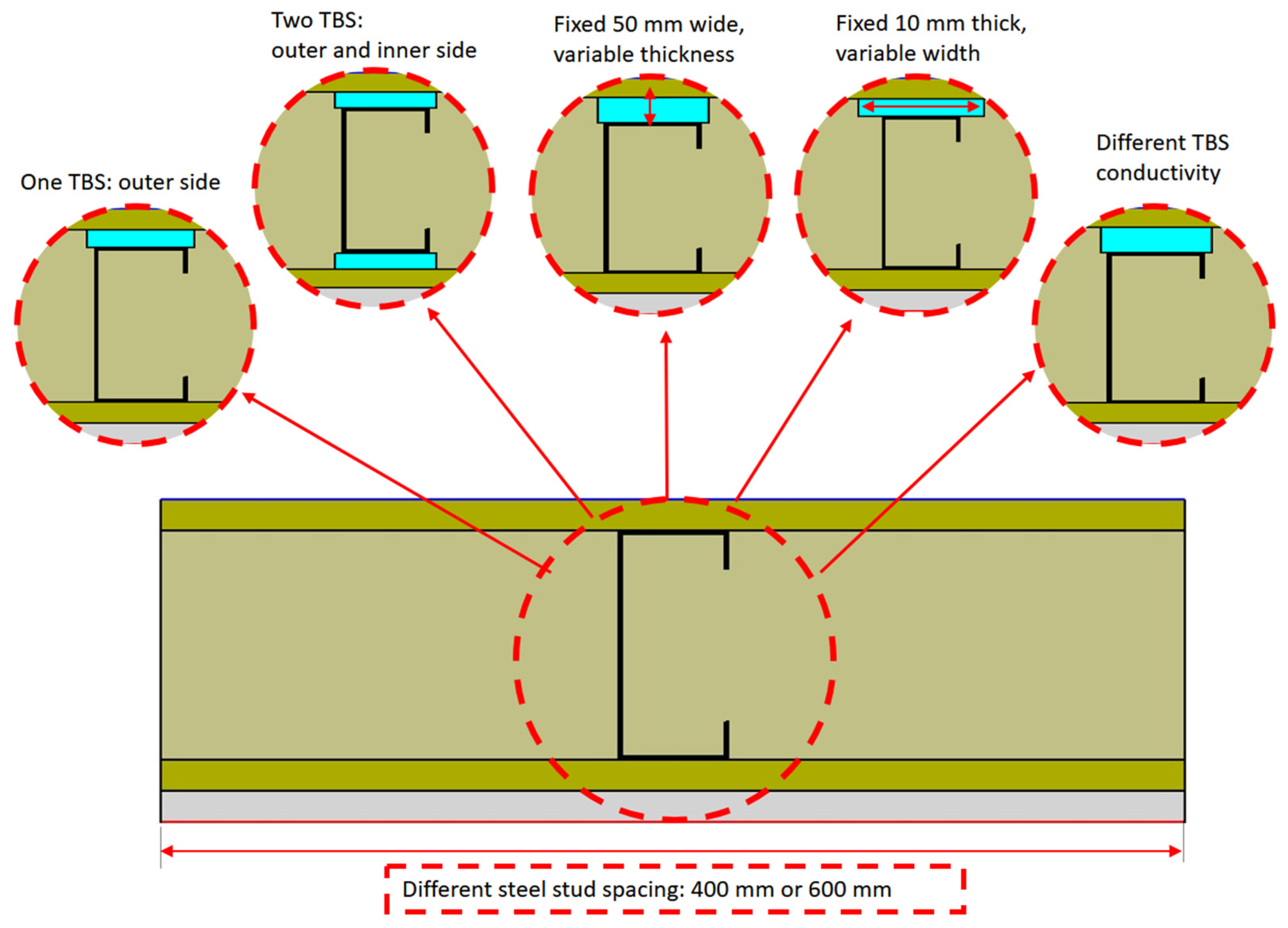
2.2. Evaluated Parameters and Values

Table 1 displays the five evaluated parameters in this sensitivity analysis, as well as their respective values. These five parameters, which are also illustrated in Figure 2, were the TBS thickness, width, and thermal conductivity and number, as well as the steel studs’ spacing.
Regarding the TBS evaluated values:
(1)
their cross-section width was fixed (50 mm) and their thickness was changed within the interval of 5–15 mm, with an increment of 2.5 mm;
(2)
their thickness was fixed (10 mm) and their width ranged within the interval of 30–70 mm, with an increment of 10 mm;
(3)
for the two previous evaluated parameters, five different TBS thermal conductivities were studied (7.5, 15, 30, 60, and 120 mW/m/K);
(4)
the number of TBS was zero (without TBS), one TBS (outer flange side), and two TBS (both inner and outer flange side).
The fifth parameter was the vertical steel stud spacing on the LSF partition walls, which was 400 and 600 mm.
In this parametric study it was assumed that the mineral wool, given its high expansion capacity, was able to fill the increased air cavity layer created by introducing the TBS along the steel stud flange, as shown in Figure 2.

2.3. Characterization of Materials

The utilized materials in the LSF walls are displayed in Table 2, with their respective thicknesses, t , as well as their thermal conductivities, λ . Note that the thermal conductivities and the dimensions of the evaluated TBS were previously displayed in Table 2.

2.4. Numerical Simulations

The LSF walls’ numerical simulations were performed using the finite element method (FEM) software THERM (version 7.6.1, Lawrence Berkeley National Laboratory: Berkeley, CA, USA) [33]. In the next subsections, the details of the numerical models will be explained, starting with the domain discretization, followed by the boundary conditions and the model accuracy verifications and validation.

2.4.1. Discretization of the Models’ Domain

Only a representative bidimensional segment of the LSF walls’ cross-sections were modelled, as illustrated in Figure 1, for the reference LSF walls (400 mm width) in order to decrease computation time and effort. The materials’ thermal properties were previously presented in Table 1 and Table 2. The maximum error accepted on the FEM calculations was set to 2% for the models assessed in this work.

2.4.2. Boundary Conditions

The environment air temperatures and the surface thermal resistances were the two sets of boundary conditions defined for each model. In this parametric study, the exterior air temperature was set to 0 °C, while the interior air temperature was set to 20 °C. Regarding superficial thermal resistances, we used the default values for horizontal heat flow indicated in ISO 6946 [34], i.e., 0.04 and 0.13 m2∙K/W for external (Rse) and internal resistance (Rsi), respectively.

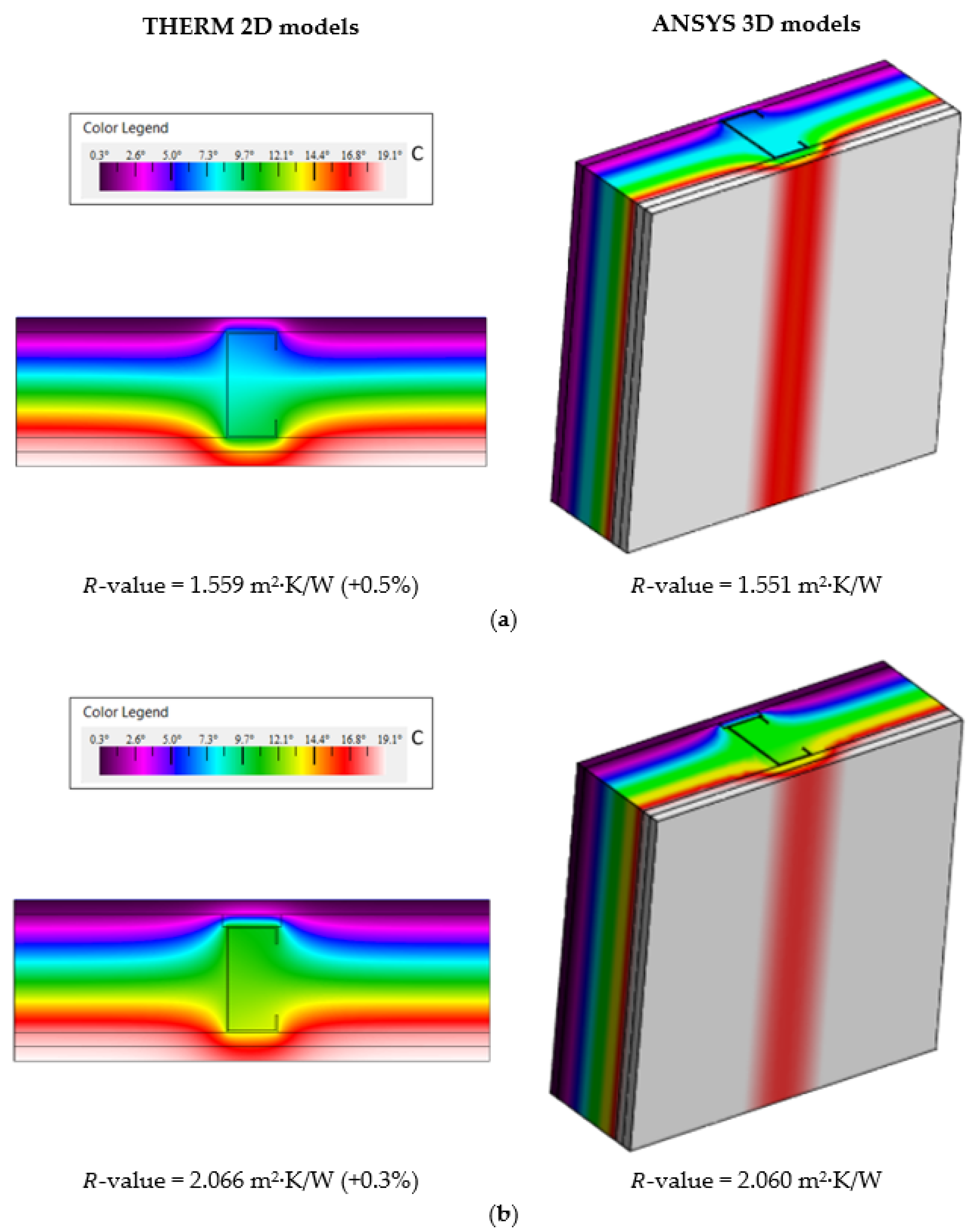
2.4.3. Verifications of Model Accuracy and Validation

For the accuracy verification of the 2D THERM software [33] models, 3 verifications were performed: (1) the ISO 10211 (Annex C) [35] test cases; (2) the analytical approach following ISO 6946 [34], assuming homogeneous layers, i.e., walls with no steel studs, and; (3) by comparison with the results provided by 3D simulations performed in the ANSYS FEM software [36]. For the model validation, experimental lab measurements were performed, as detailed in the following paragraphs.
(1)
ISO 10211 Test Cases Verification
The first accuracy verification was to model two distinct bidimensional test-cases specified in Annex C of standard ISO 10211 [35]. The achieved results were within the tolerance range and are not displayed here for the sake of conciseness. However, they can be found in earlier scientific papers, e.g., [26,37,38] by the same author, confirming the accuracy of this 2D FEM software algorithm and the models.
(2)
ISO 6946 Analytical Approach Verification
In this second precision confirmation, simplified LSF walls were assumed by making use of homogeneous layers (i.e., having no steel frame), for which the standard ISO 6946 analytical values were compared. This comparison was performed for a wall similar to the reference LSF partition. The input values, such as thermal conductivities, thicknesses of the layers, and used materials, were previously displayed in Table 1. The adopted superficial thermal resistances were prescribed by the standard ISO 6946 [34] for horizontal heat flow, as presented in Section 2.4.2. The obtained results for the numerical and analytical thermal transmittances are listed in Table 3. As expected, the numerical and analytical results perfectly matched, confirming the accuracy of the implemented THERM models [33].
(3)
3D FEM Verification
The last accuracy verification was performed by comparing the THERM 2D model results for the LSF partitions with some 3D models implemented in the ANSYS software [36]. The thermal conductivities of the modelled materials are presented in Table 1 and Table 2; the LSF partition wall dimensions and geometry are displayed in Figure 1; and for the boundary conditions, the values used in the models are the values presented in Section 2.4.2. Figure 3 displays the distribution of temperature and the computed conductive thermal resistances ( R -values) for the reference LSF partition wall (Figure 3a) and for an LSF partition with an outer TBS (Figure 3a), using both 2D and 3D models. The modelled TBS was 50 mm wide, 10 mm thick, and had a thermal conductivity equal to 30 mW/(m‧K). The obtained 2D and 3D models’ R -values were very similar (+0.5% and +0.3% difference), highlighting again the excellent THERM [33] model accuracy.
(4)
Lab Measurement Validation
To validate the THERM model, experimental measurements were performed under laboratory-controlled conditions (Figure 4) using a test sample of the reference LSF partition wall. This test-sample LSF wall was placed between two climatic chambers, as illustrated in Figure 4a. Electrical thermal resistance was used to heat the hot chamber, while a refrigerator was used to cool the cold chamber. The wall sample perimeter was covered by 80 mm foam insulation made of polyurethane with a thermal conductivity equal to 0.036 W/(m·K). The objective was to mitigate the heat losses across the sample wall’s perimeter, as shown in Figure 4a.
Two heat flux meters (model HFP01, from Hukseflux) with an accuracy of ±3% and 6 PFA insulated thermocouples (TCs), Type K (1/0.315), class 1 precision certified, were used on each face (outer and inner) of the LSF wall test-sample (cold and hot), totalling 4 heat flux meters (HFM) and 12 TCs.
On both sides, one HFM was placed over the middle metallic stud, and the other in the central region of the batt insulation, as displayed in Figure 4b, to obtain the measurements of both dissimilar thermal behaviour regions within the partition of the LSF test sample.
The TCs were placed in different locations: two were placed to measure the wall surface temperature near the HFM, and two were placed over the HFM to monitor the air temperature in the vicinity of the wall surface, and, as illustrated for the cold surface in Figure 4b, the remaining two TCs were put inside the climatic chamber to measure the environment air temperature.
The cold and hot chambers were set to preserve a temperature of 5 °C and 40 °C, respectively. To ensure a nearly steady-state heat transfer condition and to mitigate the surrounding heat transmission, these chambers were adequately insulated.
The temperature and heat flux data measurements were registered using two PICO TC-08 data loggers, with an accuracy of ±0.5%; one on each surface of the LSF partition sample (cold and hot). The recorded data were managed by the software PicoLog® (version 6.1.10) [39].
The LSF partition thermal performance was quantified using the HFM method [40], adjusted for two HFM sensors, one on each wall surface, to increase the measurement accuracy and reduce the time duration of the tests, as suggested by Rasooli and Itard [41].
The lowest time duration for each experimental test was twenty-four hours. Moreover, only the hourly average R -values with an absolute change lower than 10% in relation to the previous recorded thermal transmittance were included in the measurements. The “summation technique”, as defined in standard ASTM C1155-95 [42], was adopted for the convergence criteria.
The experimental measurements’ repeatability was ensured by performing, for each sample LSF partition, a test at three height locations: (1) bottom, (2) middle, and (3) top, as illustrated in Figure 4b.
Table 4 displays the conductive R -values measured for the three height positions and the corresponding average conductive thermal resistance for the reference partition LSF wall. The conductive R -value predicted by the THERM 2D model is also displayed in this table. The very small differences between the measured and the numerical predicted R -values (only +0.1%) indicated the accuracy of the presented THERM models and allowed for their validation.

3. Results and Discussion

3.1. Reference Partition LSF Wall

A representative horizontal transversal section of the reference partition LSF wall, with commercial cold formed studs C90 × 43 × 15 × 1.5 spaced 400 mm apart, was previously displayed in Figure 1. Their predicted conductive R -value is 1.559 m2∙K/W (see Figure 3a). When this steel stud spacing is increased to 600 mm, their R -value is augmented to 1.851 m2∙K/W (+19%). As expected, given the reduced steel content by wall area, increasing the metallic studs’ spacing improves the LSF partition’s thermal performance.

3.2. One Thermal Break Strip

In this subsection, the computed results when using a single thermal break strip, placed in the outer steel stud flange, are presented.

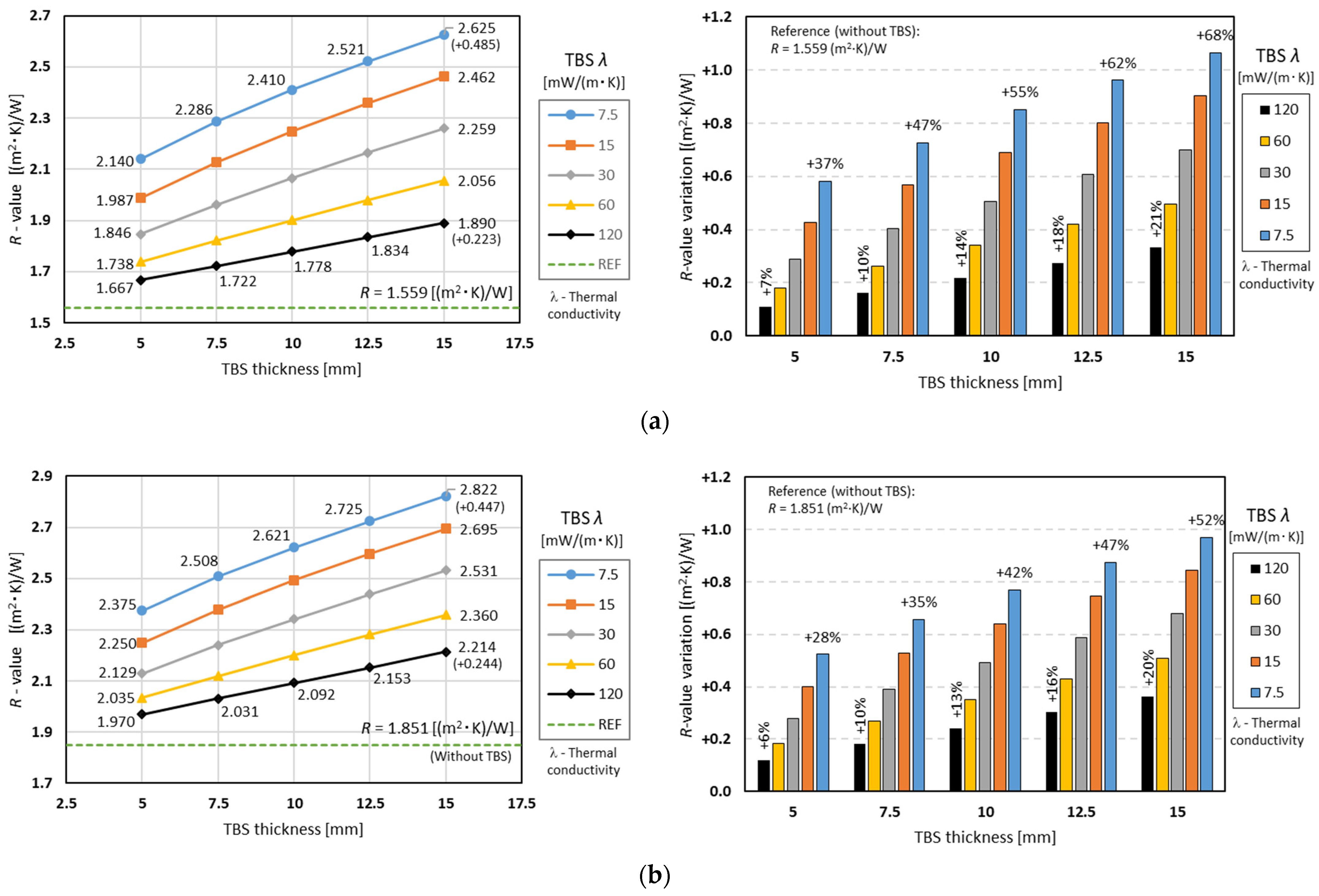
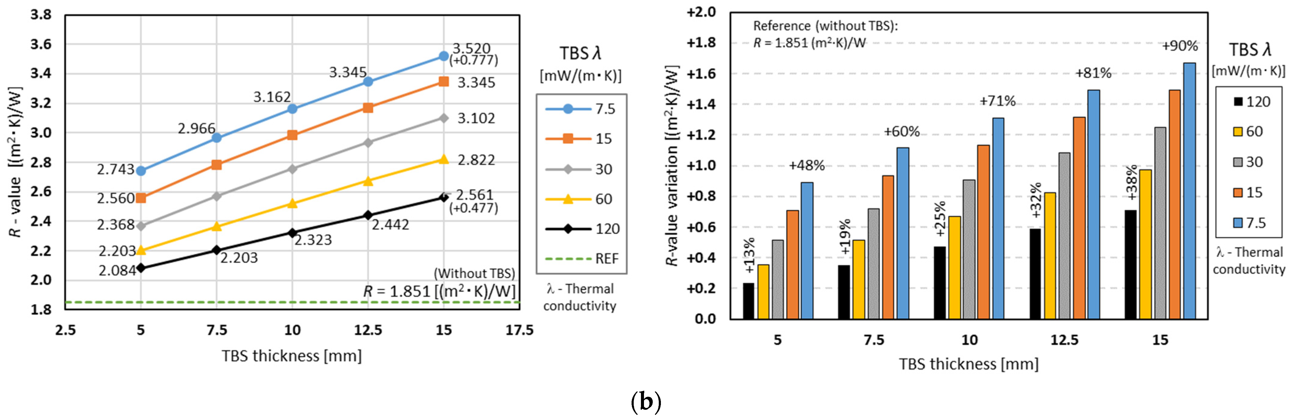
3.2.1. The Influence of TBS Thickness and Conductivity

Figure 5a exhibits the conductive thermal resistances computed for the partition LSF walls with a single TBS of variable thicknesses and 50 mm width when the steel studs were spaced at intervals of 400 mm. Each line corresponds to a specific thermal conductivity of the TBS material, from 7.5 up to 120 mW/m/W. Looking to the R -values for the higher thermal conductivity (black line), even the thinner TBS (5 mm) allowed a thermal performance increase from 1.559 m2·K/W (reference value) to 1.667 m2·K/W (+7%). When the TBS thickness increased up to 15 mm, the R -value also increased up to 1.890 m2·K/W, with a nearly linear variation. As illustrated in the right graph of Figure 5, this R -value variation, in relation to the reference wall, increased from +7% (5 mm thick) up to +21% (15 mm thick).
In terms of the other evaluated TBS thermal conductivities, the slope of the corresponding R -value lines also increased with decreasing TBS conductivity. As expected, the major R -values were achieved for the smaller TBS thermal conductivity (7.5 mW/m/W), ranging from 2.140 m2·K/W (5 mm thick) up to 2.625 m2·K/W (15 mm thick). In percentages, these R -value increments corresponded to +37% up to +68%.
Figure 5b displays two similar charts, but instead of 400 mm steel stud spacing, these R -values were obtained for 600 mm spacing. This plot shows a similar trend, but all the obtained thermal resistance values were higher than the previous ones, including the reference (1.851 m2·K/W), as previously mentioned. Another difference is that (Figure 5) for the same TBS thickness, the thermal performance improvement due to the TBS conductivity decrease was smaller in relation to the 400 mm steel stud spacing, Figure 5a. Similarly, the relevance of the TBS thickness increase in the partition LSF wall’s thermal performance improvement was greater for higher TBS conductivities (increased black line slope) and smaller for lower TBS conductivities (reduced blue line slope). Obviously, due to a higher reference R -value for the 600 mm stud spacing (Figure 5b), all percentage values became smaller, with this reduction being greater for smaller thermal conductivities.
Regardless of the thermal conductivity of the TBS, increasing its thickness always leads to better performance, as increasing the thickness of the TBS also increases the MW (due to its volumetric expansion).

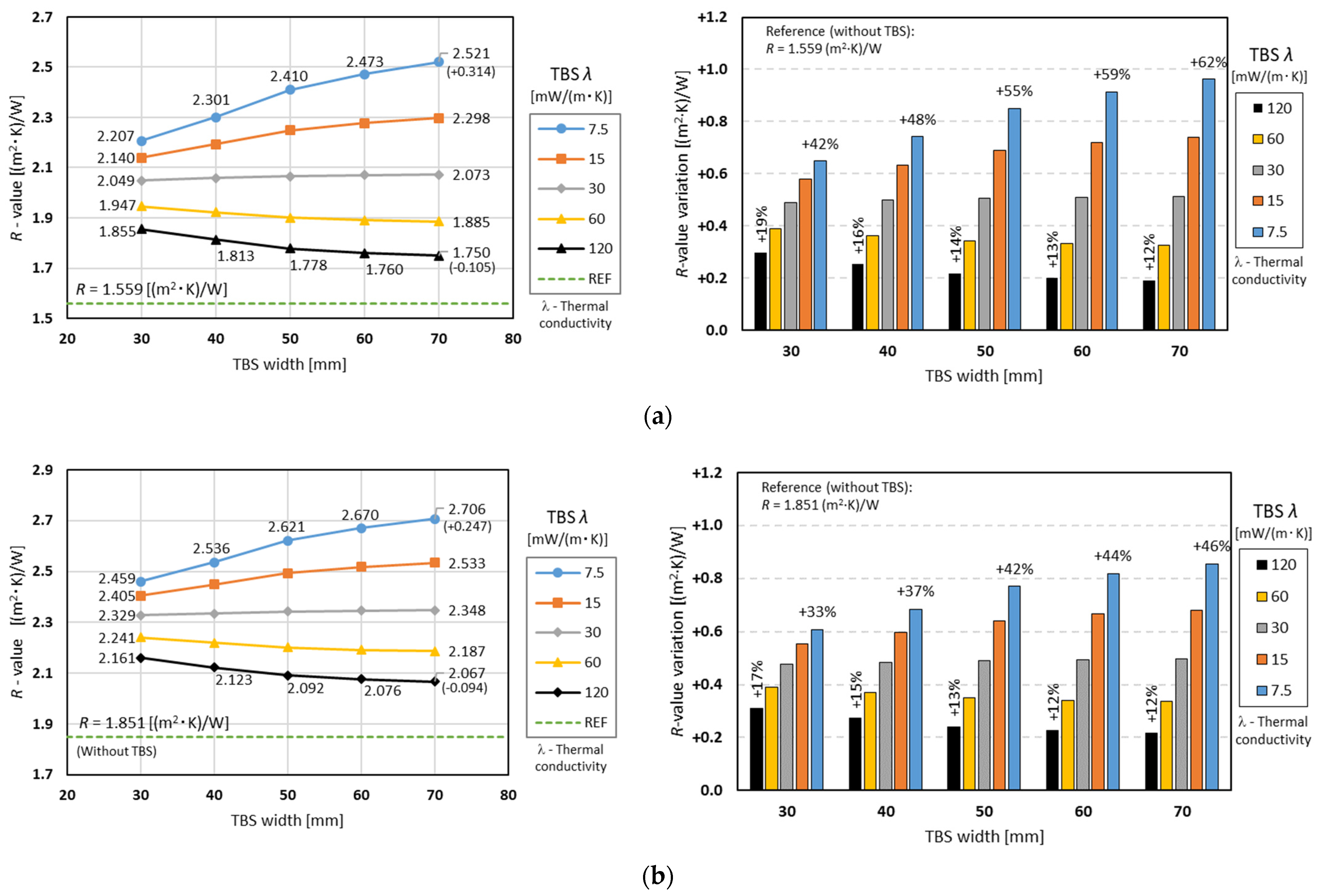
3.2.2. The Influence of TBS Width and Conductivity

Figure 6a illustrates the conductive thermal resistance values obtained for the partition LSF walls with one attached TBS of 10 mm thickness and variable width, for a 400 mm steel stud spacing, as well as the R -values variation relative to a reference wall (without TBS). The R -values for the higher thermal conductivity (120 mW/m/W), black line, even for a 30 mm width and 10 mm thickness, showed that TBS increases thermal performance from 1.559 m2·K/W (reference value) to 1.855 m2·K/W (+19%).
Surprisingly, when the TBS width increased up to 70 mm, the R -value decreased to 1.750 m2·K/W, with a small negative variation (−0.105 m2·K/W). Analysing the grey line (thermal conductivity equal to 30 mW/m/W), there was almost no variation of the thermal resistance when increasing the width of the TBS, starting at 2.049 and going up to 2.073 m2·K/W. The lower thermal conductivity (7.5 mW/m/W), blue line, presented the largest increase in relation to the reference LSF wall without TBS (1.559 up to 2.207 m2·K/W), and also with the increase in width from 30 to 70 mm, with a +0.314 m2·K/W variation.
Figure 6b displays a similar chart, but instead of 400 mm steel stud spacing, these R -values were obtained for 600 mm spacing. This plot has a similar trend, but all the obtained thermal resistance values were higher than the previous ones, including the reference (1.851 m2·K/W), as previously mentioned. The thermal resistance increase was reduced for smaller thermal conductivities (e.g., 7.5 mW/(m·K)) and slightly increased for larger thermal conductivities (e.g., 120 mW/(m·K)), as shown on the right-hand graphs.
Comparing Figure 5 and Figure 6, the TBS of 30 mm width and 10 mm thickness (Figure 6) presented higher R -values than a TBS of 50 mm width and 5 mm thickness (Figure 5). However, increasing the TBS thickness (Figure 5) up to 15 mm is more advantageous (higher R -values) than increasing the TBS width (Figure 6) up to 70 mm due to the increase in the wall cavity thickness whenever the TBS thickness increases. Given the MW natural expansion, the thickness of this thermal insulation also increases, which leads to an incremental change of the overall R -value of the LSF partition wall.
Moreover, increasing the TBS thickness always leads to an increased thermal resistance (Figure 5), while the increase in the TBS width for higher thermal conductivity values may lead to a decreased thermal performance (Figure 6). This happens whenever the TBS material has a thermal conductivity that is higher than the batt insulation (in this case, mineral wool with 35 mW/m/K). In Figure 6, the grey line, corresponding to a TBS thermal conductivity of 30 mW/m/K, was the nearest one, where the thermal resistance was slightly increasing. However, as expected, there was an increased R -value diminishment for the yellow (60 mW/m/K) and black (120 mW/m/K) lines, given their higher TBS thermal conductivities.

3.3. Two Thermal Break Strips

Here, the results when using two TBS are presented and compared with the previous results (single TBS).

3.3.1. The Influence of TBS Thickness and Conductivity

Figure 7a exhibits the conductive thermal resistances obtained for the partition LSF walls with two TBS of 50 mm width and variable thicknesses when the steel studs were spaced 400 mm. Based on the R -values for the higher thermal conductivity (120 mW/m/W), black line, even the thinner TBS (5 mm) allowed a thermal performance increase from 1.559 m2·K/W (reference value) to 1.769 m2·K/W (+13%). When the TBS thickness increased up to 15 mm, the R -value also increased up to 2.204 m2·K/W (+41% relative to the reference LSF wall), with a nearly linear variation.
Looking to the other evaluated TBS thermal conductivities, the slope of the corresponding R -value lines also increased with the decreasing TBS conductivity. Once again, the major R -values were reached for the smaller TBS thermal conductivity (7.5 mW/m/W), ranging from 2.569 m2·K/W (5 mm thick, +65%) up to 3.419 m2·K/W (15 mm thick, +119%).
Figure 7b displays a similar chart, but instead of 400 mm steel stud spacing, these R -values were obtained for 600 mm spacing. This plot shows a similar trend, but all obtained thermal resistance values were higher than the previous ones. Another difference is that (Figure 7b) for the same TBS thickness, the thermal performance improvement due to the TBS conductivity decrease was smaller in relation to the previous values for the 400 mm steel stud spacing Figure 7a. As mentioned before, the relevance of the TBS thickness increase to the partition LSF wall thermal performance improvement was smaller for the 600 mm spacing, with this being more visible for the smaller TBS thermal conductivities.

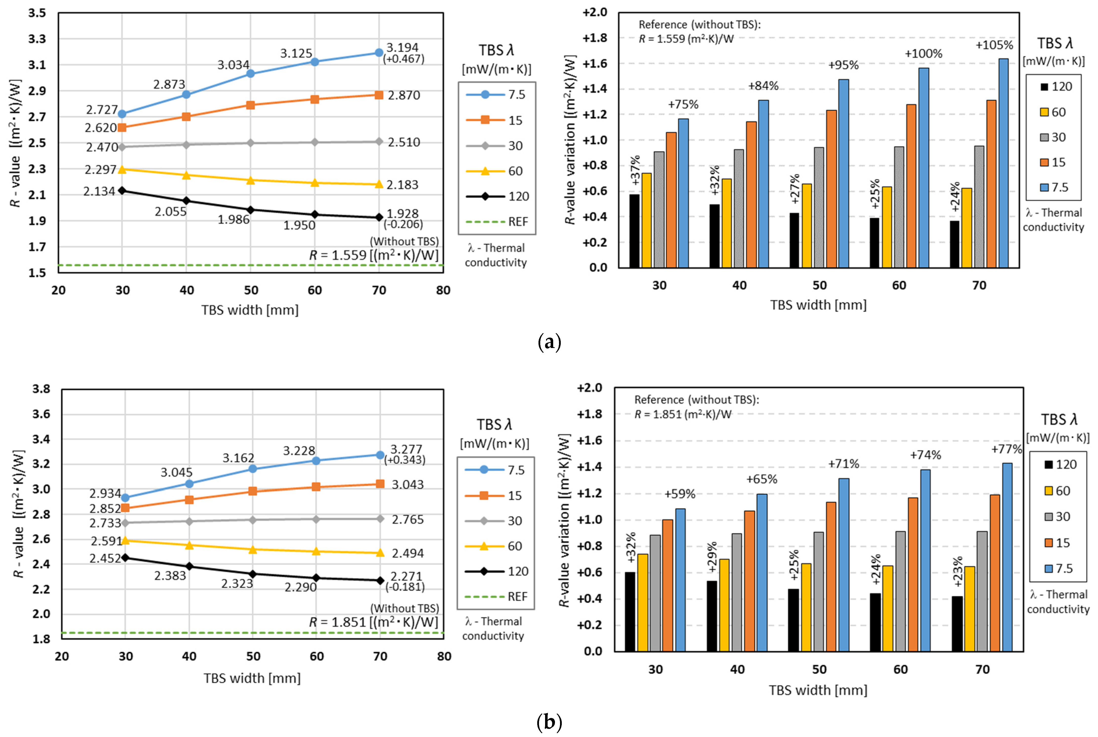
3.3.2. The Influence of TBS Width and Conductivity

Figure 8a exhibits the conductive thermal resistance values obtained for the partition LSF walls with two TBS of 10 mm thickness and variable width when the steel studs were spaced 400 mm apart. The R -values for the higher thermal conductivity (120 mW/m/W), black line, showed that two TBS of 30 mm width and 10 mm thickness allowed a thermal performance increase from 1.559 m2·K/W (reference value) up to 2.134 m2·K/W (+37% relative to the reference LSF partition wall). When the TBS width increased up to 70 mm, the R -value decreased to 1.928 m2·K/W, corresponding to +24% relative to the reference partition (without TBS). Analysing the grey line (thermal conductivity of 30 mW/m/W), once again we observed that there was a very reduced variation of the R -value when increasing the width of the TBS (2.470 to 2.510 m2·K/W). The lower thermal conductivity (7.5 mW/m/W), as expected (blue line), presented the largest increase in relation to the reference (1.559 to 2.727 m2·K/W, +75%), and with the increase in width from 30 to 70 mm, presented a 0.467 m2·K/W variation.
Figure 6b displays a similar chart, but instead of 400 mm steel stud spacing, these R -values were obtained for 600 mm spacing. This plot shows a similar trend, but all the obtained thermal resistance values were higher than the previous values, including the reference (1.851 m2·K/W), as previously mentioned.
Comparing Figure 7 (TBS thickness relevance) and Figure 8 (TBS width relevance), it can be observed, once again, that a TBS with 30 mm width and 10 mm thickness presented higher R -values (Figure 8) than a TBS with 50 mm width and 5 mm thickness (Figure 7). However, the increase in TBS thickness (Figure 7) was more effective at improving the overall partition thermal performance than the increment of TBS width for all evaluated TBS thermal conductivities. Moreover, as seen before (one TBS), an increase in TBS width for higher thermal conductivity materials is counter-productive, i.e., will decrease their R -value.

4. Conclusions

In this research, the relevance of TBS to the thermal performance improvement of load-bearing LSF partitions was assessed through a parametric study. The bidimensional numerical models used in this study were previously validated, and their accuracy and reliability ensured. Five different key parameters were changed and their importance evaluated, namely the TBS thickness, width, thermal conductivity, and number, as well as the vertical steel stud spacing.
The key conclusions of this parametric study are as follows:
  • As expected, only by increasing the vertical steel stud spacing from 400 mm to 600 mm did we achieve a relevant thermal resistance improvement (+19%).
  • Regardless of the TBS thermal conductivity, it is always worth increasing the thickness of the TBS due to the consequent increase in the wall cavity thickness and the resulting expansion of the batt insulation (in this study, mineral wool).
  • Moreover, regardless of the evaluated TBS conductivities, the thermal resistances provided by the smaller assessed TBS width (30 mm) were always bigger than the ones provided by the smaller evaluated TBS thickness (5 mm).
  • Surprisingly, the increase in the TBS width did not always lead to increased thermal resistance.
  • In fact, for higher TBS conductivities, a thermal performance reduction occurred when increasing the width of the TBS.
  • The previous happens whenever the thermal conductivity of the TBS is greater than the conductivity of the expansible batt insulation.
  • Considering the preceding features, it was concluded that it is more effective to increase the TBS thickness rather than the width.
  • The abovementioned features are more relevant for smaller stud spacing (400 mm instead of 600 mm) and when using two TBS instead of a single one.
Regarding the TBS thickness higher effectiveness, comparatively to increasing their width, notice that this conclusion is also valid for other expansible thermal insulation materials, as the TBS thickness increase will directly induce a batt insulation thickness increase and consequent thermal performance improvement. Obviously, this LSF wall overall thermal resistance rise will depend on the thermal conductivity of the adopted batt insulation, and it will be higher for lower conductivities.
The two main limitations of this research were that (1) only LSF partition walls with vertical steel studs were considered, and (2) only one batt insulation material (mineral wool) was used. To overcome the first restriction, 3D numerical models instead of 2D models, as previously illustrated in Figure 3, could be used. Regarding the second limitation, it was assumed that the mineral wool batt insulation was expansible enough to fill the LSL wall cavity.
This research allowed us to better understand, quantify, and compare the effectiveness of TBS for the thermal performance improvement of load-bearing partition LSF walls, which was not previously available in the literature. This knowledge could be useful for designers when they need to decide the cross-section dimensions of the TBS, as well as the material thermal conductivity and the number of TBS.

Author Contributions

Conceptualization, P.S.; Methodology, P.S., P.L. and D.A.; Validation, P.S. and P.L.; Formal analysis, P.L. and D.A.; Investigation, P.S., P.L. and D.A.; Resources, P.S.; Writing—original draft, P.L. and D.A.; Writing—review & editing, P.S.; Visualization, P.S. and D.A.; Supervision, P.S.; Project administration, P.S.; Funding acquisition, P.S. All authors have read and agreed to the published version of the manuscript.

Funding

This research was funded by FEDER funds through the Competitivity Factors Operational Programme–COMPETE, and by national funds through FCT, Foundation for Science and Technology, within the scope of the project POCI-01-0145-FEDER-032061.Energies 15 09271 i001

Acknowledgments

The authors also want to thank the following companies: Pertecno, Gyptec Ibéria, Volcalis, Sotinco, Kronospan, Hulkseflux, Hilti, and Metabo.

Conflicts of Interest

The authors declare no conflict of interest.

References

  1. Energy Efficiency in Buildings; European Commission, Department Energy: Brussels, Belgium, 2020.
  2. Global Alliance of Buildings and Construction. 2021 Global Status Report for Buildings and Construction; United Nations Environment Programme: Nairobi, Kenya, 2021. [Google Scholar]
  3. EU. Directive 8(EU) 2018/844 of the European Parliament and of the Council on the energy performance of buildings and on energy efficiency. Off. J. Eur. Union 2018, 2018, 75–91. [Google Scholar]
  4. EU. Directive (EU) 2018/2001 of the European Parliament and of the Council on the promotion of the use of energy from renewable sources. Off. J. Eur. Union 2018, 2018, 82–209. [Google Scholar]
  5. Zhan, Q.; Xiao, Y.; Musso, F.; Zhang, L. Assessing the hygrothermal performance of typical lightweight steel-framed wall assemblies in hot-humid climate regions by monitoring and numerical analysis. Build. Environ. 2020, 188, 107512. [Google Scholar] [CrossRef]
  6. Soares, N.; Santos, P.; Gervásio, H.; Costa, J.J.; da Silva, L.S. Energy efficiency and thermal performance of lightweight steel-framed (LSF) construction: A review. Renew. Sustain. Energy Rev. 2017, 78, 194–209. [Google Scholar] [CrossRef]
  7. Perera, D.; Upasiri, I.; Poologanathan, K.; Gatheeshgar, P.; Sherlock, P.; Hewavitharana, T.; Suntharalingam, T. Energy performance of fire rated LSF walls under UK climate conditions. J. Build. Eng. 2021, 44, 103293. [Google Scholar] [CrossRef]
  8. Kapoor, D.R.; Peterman, K.D. Quantification and prediction of the thermal performance of cold-formed steel wall assemblies. Structures 2021, 30, 305–315. [Google Scholar] [CrossRef]
  9. Kempton, L.; Kokogiannakis, G.; Green, A.; Cooper, P. Evaluation of thermal bridging mitigation techniques and impact of calculation methods for lightweight steel frame external wall systems. J. Build. Eng. 2021, 43, 102893. [Google Scholar] [CrossRef]
  10. Ge, H.; Baba, F. Dynamic effect of thermal bridges on the energy performance of a low-rise residential building. Energy Build. 2015, 105, 106–118. [Google Scholar] [CrossRef]
  11. Erhorn-Kluttig, H.; Erhorn, H. Impact of Thermal Bridges on the Energy Performance of Buildings; Buildings Platform; European Communities: Brussels, Belgium, 2009; pp. 1–8. [Google Scholar]
  12. Al-Sanea, S.A.; Zedan, M. Effect of thermal bridges on transmission loads and thermal resistance of building walls under dynamic conditions. Appl. Energy 2012, 98, 584–593. [Google Scholar] [CrossRef]
  13. Theodosiou, T.; Papadopoulos, A. The impact of thermal bridges on the energy demand of buildings with double brick wall constructions. Energy Build. 2008, 40, 2083–2089. [Google Scholar] [CrossRef]
  14. Jedidi, M.; Benjeddou, O. Effect of Thermal Bridges on the Heat Balance of Buildings. Int. J. Sci. Res. Civ. Eng. 2018, 2, 2456–6667. [Google Scholar]
  15. Santos, P.; Silva, L.; Ungureanu, V. Energy Efficiency of Lightweight Steel-Framed Buildings; Technical Committee 14-Sustainability & Eco-Efficiency of Steel Construction; European Convention for Constructional Steelwork (ECCS): Brussels, Belgium, 2012; ISBN 978-92-9147-105-8. [Google Scholar]
  16. Martins, C.; Santos, P.; Simoesdasilva, L. Lightweight steel-framed thermal bridges mitigation strategies: A parametric study. J. Build. Phys. 2015, 39, 342–372. [Google Scholar] [CrossRef]
  17. Santos, P.; Poologanathan, K. The importance of stud flanges size and shape on the thermal performance of lightweight steel framed walls. Sustainability 2021, 13, 3970. [Google Scholar] [CrossRef]
  18. Atsonios, I.A.; Mandilaras, I.D.; Kontogeorgos, D.A.; Founti, M.A. Two new methods for the in-situ measurement of the overall thermal transmittance of cold frame lightweight steel-framed walls. Energy Build. 2018, 170, 183–194. [Google Scholar] [CrossRef]
  19. François, A.; Ibos, L.; Feuillet, V.; Meulemans, J. In situ measurement method for the quantification of the thermal transmittance of a non-homogeneous wall or a thermal bridge using an inverse technique and active infrared thermography. Energy Build. 2021, 233, 110633. [Google Scholar] [CrossRef]
  20. Santos, P.; Lemes, G.; Mateus, D. Analytical Methods to Estimate the Thermal Transmittance of LSF Walls: Calculation Procedures Review and Accuracy Comparison. Energies 2020, 13, 840. [Google Scholar] [CrossRef] [Green Version]
  21. Santos, P.; Mateus, D. Experimental assessment of thermal break strips performance in load-bearing and non-load-bearing LSF walls. J. Build. Eng. 2020, 32, 101693. [Google Scholar] [CrossRef]
  22. Santos, P.; Abrantes, D.; Lopes, P.; Mateus, D. Experimental and Numerical Performance Evaluation of Bio-Based and Recycled Thermal Break Strips in LSF Partition Walls. Buildings 2022, 12, 1237. [Google Scholar] [CrossRef]
  23. Santos, P.; Mateus, D.; Ferrandez, D.; Verdu, A. Numerical Simulation and Experimental Validation of Thermal Break Strips’ Improvement in Facade LSF Walls. Energies 2022, 15, 8169. [Google Scholar] [CrossRef]
  24. Gomes, A.P.; de Souza, H.A.; Tribess, A. Impact of thermal bridging on the performance of buildings using Light Steel Framing in Brazil. Appl. Therm. Eng. 2012, 52, 84–89. [Google Scholar] [CrossRef] [Green Version]
  25. Kosny, J.; Christian, J.E. Thermal evaluation of several configurations of insulation and structural materials for some metal stud walls. Energy Build. 1995, 22, 157–163. [Google Scholar] [CrossRef]
  26. Santos, P.; Gonçalves, M.; Martins, C.; Soares, N.; Costa, J.J. Thermal transmittance of lightweight steel framed walls: Experimental versus numerical and analytical approaches. J. Build. Eng. 2019, 25, 100776. [Google Scholar] [CrossRef]
  27. Lupan, L.M.; Manea, D.L.; Moga, L.M. Improving Thermal Performance of the Wall Panels Using Slotted Steel Stud Framing. Procedia Technol. 2016, 22, 351–357. [Google Scholar] [CrossRef]
  28. Henriques, J.; Rosa, N.; Gervasio, H.; Santos, P.; da Silva, L.S. Structural performance of light steel framing panels using screw connections subjected to lateral loading. Thin Walled Struct. 2017, 121, 67–88. [Google Scholar] [CrossRef]
  29. Ibérica, G. Technical Sheet: Standard Gypsum Plasterboard. 2022. Available online: https://www.gyptec.eu/documentos/Ficha_Tecnica_Gyptec_A.pdf (accessed on 10 February 2022).
  30. Kronospan. Technical Sheet: Kronobuild Materials; Kronospan GmbH: Steinheim-Sandebeck, Germany, 2013. [Google Scholar]
  31. Volcalis. Technical Sheet: Alpha Mineral Wool. 2022. Available online: https://www.volcalis.pt/categoria_file_docs/fichatecnica_volcalis_alpharollo-386.pdf (accessed on 10 February 2022).
  32. Santos, C.; Matias, L. ITE50—Coeficientes de Transmissão Térmica de Elementos da Envolvente dos Edifícios (in Portuguese); LNEC—Laboratório Nacional de Engenharia Civil: Lisboa, Portugal, 2006. [Google Scholar]
  33. THERM. Software Version 7.6.1. Lawrence Berkeley National Laboratory, United States Department of Energy. 2017. Available online: https://windows.lbl.gov/software/therm (accessed on 14 February 2019).
  34. ISO 6946; Building Components and Building Elements—Thermal Resistance and Thermal Transmittance—Calculation Methods. ISO—International Organization for Standardization: Geneva, Switzerland, 2017.
  35. ISO 10211; Thermal Bridges in Building Construction-Heat Flows and Surface Temperatures-Detailed. ISO—International Organization for Standardization: Geneva, Switzerland, 2017.
  36. ANSYS Workbench Software, Version 19.1; ANSYS, Inc.: Canonsburg, PA, USA, 2018. Available online: http://www.ansys.com/products/(accessed on 8 June 2020).
  37. Roque, E.; Santos, P. The effectiveness of thermal insulation in lightweight steel-framedwalls with respect to its position. Buildings 2017, 7, 13. [Google Scholar] [CrossRef] [Green Version]
  38. Santos, P.; Lemes, G.; Mateus, D. Thermal transmittance of internal partition and external facade LSF walls: A parametric study. Energies 2019, 12, 2671. [Google Scholar] [CrossRef] [Green Version]
  39. Pico Technology. PicoLog 6 Software, Version 6.1.10. 2019. Available online: https://www.picotech.com/downloads (accessed on 1 September 2022).
  40. ISO 9869-1; Thermal Insulation–Building Elements—In-Situ Measurement of Thermal Resistance and Thermal Transmittance. Part 1: Heat Flow Meter Method. ISO—International Organization for Standardization: Geneva, Switzerland, 2014.
  41. Rasooli, A.; Itard, L. In-situ characterization of walls’ thermal resistance: An extension to the ISO 9869 standard method. Energy Build. 2018, 179, 374–383. [Google Scholar] [CrossRef]
  42. ASTM C1155-95; Standard Practice for Determining Thermal Resistance of Building Envelope Components from the In-Situ Data. ASTM—American Society for Testing and Materials: Philadelphia, PA, USA, 2013.
Figure 1. Reference load-bearing partition LSF wall: horizontal cross-section.
Energies 15 09271 g001
Figure 2. Evaluated parameters in the sensitivity analysis.
Energies 15 09271 g002
Figure 3. Model accuracy verification of the LSF partitions: predicted temperature distribution and surface-to-surface thermal resistance. (a) Reference LSF partition. (b) LSF partition with an outer thermal break strip.
Energies 15 09271 g003
Figure 4. Experimental apparatus for the R -value lab measurements. (a) Thermal chambers. (b) Sensors on the cold surface.
Energies 15 09271 g004
Figure 5. Conductive thermal resistances for partition LSF walls with one thermal break strip: 50 mm wide and variable thickness, for two different steel stud spacings. (a) 400 mm stud spacing. (b) 600 mm stud spacing.
Energies 15 09271 g005
Figure 6. Surface-to-surface thermal resistance for LSF partitions, with one thermal break strip: 10 mm thick and variable width, for two different steel stud spacings. (a) 400 mm stud spacing. (b) 600 mm stud spacing.
Energies 15 09271 g006
Figure 7. Conductive thermal resistance for partition LSF walls, with two thermal break strips: 50 mm wide and variable thickness. (a) 400 mm stud spacing. (b) 600 mm stud spacing.
Energies 15 09271 g007aEnergies 15 09271 g007b
Figure 8. Surface-to-surface thermal resistances for LSF partitions, with two thermal break strips: 10 mm thick and variable width. (a) 400 mm stud spacing. (b) 600 mm stud spacing.
Energies 15 09271 g008
Table 1. Parameters to be evaluated and assigned values.
Parameter“Values”
Thermal break strips:
-
Thickness [mm]
5, 7.5, 10 *, 12.5, 15
-
Width [mm]
30, 40, 50 *, 60, 70
-
Conductivity [mW/(m·K)]
7.5, 15, 30, 60, 120
-
Number
Zero *, one 1, two 2
Steel stud spacing [mm]400 *, 600
* Reference values in bold; 1 one: outer flange; 2 two: both inner and outer flanges.
Table 2. Characterization of the materials used in the partition LSF walls: thicknesses (t) and thermal conductivities (λ).
Materialt
[mm]
λ
[W/(m·K)]
Ref.
Gypsum plasterboard12.50.175[29]
Oriented strand board12.00.100[30]
Mineral wool90.00.035[31]
Steel studs (C90 × 43 × 15 × 1.5)90.050.000[32]
Table 3. Thermal transmittance computed for the simplified LSF walls assuming homogeneous layers.
LSF Wall Type U -Value [W/(m2·K)]
Numerical (THERM)Analytical (ISO 6946)
Partition0.3280.328
Table 4. Reference LSF partition wall surface-to-surface R-values for both the experimental and numerical approaches. Percentage deviation included.
Test N.Sensors Position R -Value
[m2·K/W]
1Bottom1.607
2Middle 1.576
3Top1.491
Measurement Average1.558
Computed in THERM1.559
Percentage Deviation+0.1%
Publisher’s Note: MDPI stays neutral with regard to jurisdictional claims in published maps and institutional affiliations.

