Review

A Review of Hybrid Converter Topologies

Department of Electrical Power Engineering and Mechatronics, Tallinn University of Technology, 12616 Tallinn, Estonia
*
Author to whom correspondence should be addressed.
Energies 2022, 15(24), 9341; https://doi.org/10.3390/en15249341
Submission received: 18 October 2022 / Revised: 29 November 2022 / Accepted: 6 December 2022 / Published: 9 December 2022
(This article belongs to the Special Issue Review of Advanced Power Electronics Solutions)

Abstract

:
There is a growing interest in solar energy systems with storage battery assistance. There is a corresponding growing interest in hybrid converters. This paper provides a comprehensive review of hybrid converter topologies. The concept of a hybrid inverter is introduced and then classified into isolated and non-isolated structures based on using a galvanic transformer. The classification and description of each type are presented based on the features and applications. Furthermore, the most popular commercial solutions are investigated in terms of their simplicity, flexibility, efficiency, and battery technology. The summarizing features are presented through tables, and future trends for researchers to follow to develop efficient hybrid converters are discussed. This review paper is intended as a convenient reference for hybrid converter users.

1. Introduction

Electrical energy consumption over the whole world is rapidly growing. There is a consistent increase in the demands on power capacity and the efficient production, distribution, and utilization of energy. The general power generation capacity must be increased to meet dynamic load variations [1]. A decrease in the accessibility of conventional energy resources has prompted power engineers and researchers around the globe to look for better and more productive means of the utilization of renewable energy sources (RES).
Power electronic converters play a crucial role in the usage of RES [2]. Power electronic converters are increasingly used in various applications including electric cars, ships, and photovoltaic (PV) panels. An independent power system can be formed by combining renewable energy with local loads. This approach is widely incorporated into modern power systems [3,4]. In this system, dc and ac loads are provided by different types of energy sources using efficient power electronic converters.
Figure 1a shows a simple example of a solar energy system in which a single dc source supplies an ac grid or load. Figure 1b shows the same system with battery assistance. Hybrid converters as multi-output converters are used to provide simultaneous dc and ac outputs for systems, delivering better power density and improved reliability [5,6]. Researchers have been focused on improving the performance of hybrid converters through topological innovations and control methods [7,8,9].
As a result of the limited amount of power that can be injected into the grid by renewable energy produced by local households, the feed-in energy costs of solar systems are decreasing and are expected to be zero in the current decade [10]. With this in mind, the use of battery storage systems along with renewable energy sources has great importance.
Some review papers have been published in the literature [11,12,13,14]. However, this paper focuses on the existing solutions on the market in terms of structure (simplicity), rating powers, and insulation, as well as high efficiency. The main goal of this paper is to propose a general classification of hybrid converters, as well as a brief overview of their state in the marketplace. In this regard, Section 2 presents the ancillary services of converters. Section 3 describes the various functions of the Hybrid converter. The existing solutions for hybrid converters are analyzed in Section 4. A research overview of isolated and non-isolated hybrid converters is presented in Section 5 and Section 6 respectively. Finally, the conclusion is presented in Section 7.

2. Ancillary Services of Converters

The Federal Energy Regulatory Commission (FERC) defines ancillary services as “those services necessary to support the transmission of electric power from seller to purchaser given the obligations of control areas and transmitting utilities within those control areas to maintain reliable operations of the interconnected transmission system”. They are needed for grid reliability [15]. FERC identified six ancillary services including reactive power and voltage control, loss compensation, scheduling and dispatch, load following, system protection, and energy imbalance [16]. Among these services, the power electronics converters seem to be best suited for providing reactive power and voltage control. Voltage regulation has traditionally been done on transmission lines because distribution networks are passive networks. The diffusion of RES directly connected to the distribution networks gave rise to the problem of voltage regulation on these networks. Voltage regulation can be achieved by compensating the reactive power required by the users and aims primarily to maintain voltages within certain ranges, but it is also concerned with minimizing temporal variations in voltage and harmonic distortion. The voltage that is traditionally controlled is that acting on the ratio-changing devices (e.g., transformer taps and voltage regulators), reactive-power-control devices (e.g., capacitors, static-var compensators, and occasionally synchronous condensers), and harmonic-control devices (active power filters). The system operator must monitor and control these voltages and compensate for the reactive power of the grid. Sometimes the network management may find it more economical to purchase reactive power from a customer than to directly compensate the customer for the same reactive power. In this case, some customers can provide this ancillary service to the network [17,18].
When the electrical energy conversion is made with photovoltaic (PV) arrays, an intermediate converter is needed for the connection to the grid. This converter can be either single-stage or dual-stage [19]: the first stage is a dc-dc converter, whereas the second is an inverter synchronized with the utility grid. The dc-dc converter boosts the voltage of the PV arrays up to values suitable for the PWM modulation of the inverter. Maximum Power Point Tracking control (MPPT) is usually implemented on the boost converter to extract the maximum power available from the solar source. Finally, the inverter supplies the power generated by the PV array with the desired power factor to the grid.
When PV systems are used to perform ancillary services to improve grid power quality, they pose several control challenges. For example, in harmonic compensation, it is important to detect the current or voltage harmonic information.
Reference [20] proposed a method based on conservative power theory to detect the harmonic current of the load. In [21], the Point of Common Coupling (PCC) voltage information for harmonic compensation is used through a voltage control loop. In addition, reactive power compensation methods are discussed in [22].

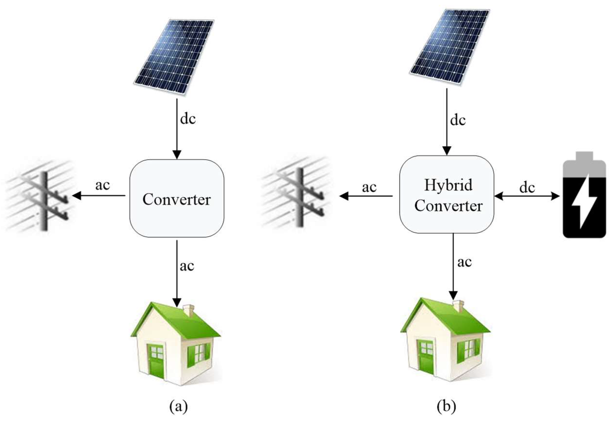
3. Functionalities of Hybrid Converters

An intelligent hybrid converter is a trending type of converter for solar applications using renewable energy for home consumption, especially for solar photovoltaic installations. Some see this as a new technology, however, in some parts of the world such products have been around since the 1990s. In solar systems, power generation fluctuates and may not be synchronized with a load’s electricity consumption since solar panels generate electricity only during the day. To fill the gap between what is produced and what is consumed during the evening when solar electricity is not produced, it is necessary to store energy for later use and to manage energy storage as well as consumption with a hybrid converter.
Hybrid converters enable the selection and orientation of renewable energy, grid energy, and energy storage based on consumption. Unlike conventional converters, which systematically store energy in batteries, hybrid converters only store energy when it is needed. This system also allows a choice between whether electricity from photovoltaic panels should be stored or consumed through an internal intelligent apparatus control unit. Hybrid converters can operate in different modes: on-grid, off-grid, hybrid (both on-grid and off-grid at the same time), and backup (in case of a black-out) as described in the following subsections.

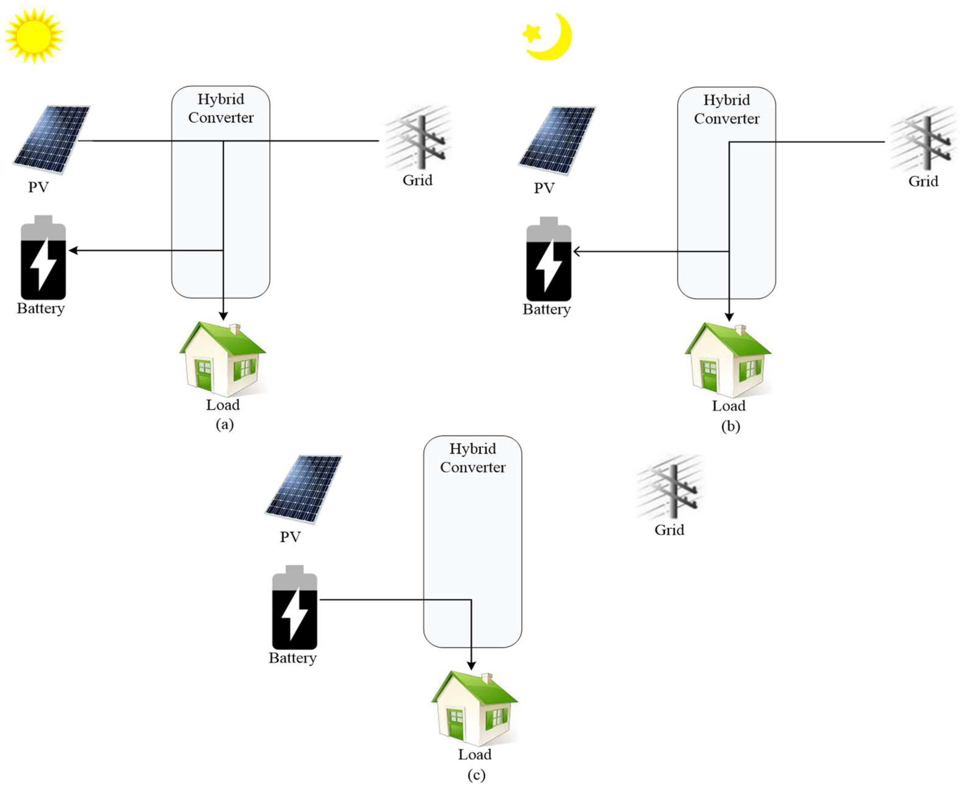
3.1. On-Grid General Mode (Hybrid)

As illustrated in Figure 2a,b respectively, if PV has sufficient power to inject the required power of the load, the surplus power of PV is used to charge the battery and feed into the grid. Conversely, when PV has insufficient power, batteries and the grid have the responsibility to supply the load.

3.2. On-Grid with Battery Backup Mode

PV and the grid both supply the load and charge the batteries (Figure 3a). When the grid is working smoothly, the battery’s State of Charge (SOC) is always in full state as depicted in Figure 3b. Batteries discharge only when a grid faults occur (Figure 3c).

3.3. Off-Grid Mode

PV and battery constitute an off-grid system. If PV can supply the required power of the load, the priority is to supply the required power to the load. Any surplus power is used to charge the battery, as shown in Figure 4a. When PV has insufficient power, the battery is used to supply power to the load (Figure 4b).

4. Analysis of Hybrid Inverters Available on the Market

The purpose of this section is to provide a comparative analysis of hybrid solar inverters on the market. Several of the most popular commercial hybrid inverters have been chosen for comparison [23]. The selected power range is from 3 kW to 5 kW, which is the typical PV power range for residential applications. All characteristics of the commercial hybrid inverters have been obtained from open sources and are shown in Table 1 [24,25,26,27,28,29,30,31,32,33,34,35]. These inverters illustrate a variety of solutions that are available on the market currently. The most popular manufacturers were selected for analysis. Most of the inverters are single-phase with an average maximum efficiency of about 97%.
As Table 1 shows, there are two types of inverters. The first type is those with a low battery voltage range such as the Sungrow SH5K-30, Redback SH5000, and Imeon 3.6. A low voltage range (42–58.8 V) leads to high charging/discharging currents. In the case of the Redback SH5000 inverter, these are 85 A/100 A, respectively. The second type is inverter is those with a high battery voltage. For example, the Solis RHI-1P5K-HVES-5G. The battery voltage of the latter varies from 120 V to 500 V. However, the charging and discharging current in this system is only 20 A. Compatible batteries for inverters are mostly Li-ion. However, according to its datasheet, the 3-phase Fronius SYMO Hybrid uses the LiFePO4-type battery technology, which guarantees a long service life, short charging times, and high depth of discharge. Furthermore, the storage capacity of the Fronius Solar Battery can be adapted to meet individual customer needs. All the selected inverters use the same standard communications—an RS485 connection or a CAN Bus.
The possible structure of the hybrid inverters is illustrated in Figure 5. They consist of solar terminals, a grid-connected Voltage Source Inverter (VSI), a buck-boost cell, which realizes the Maximum Power Point Tracking (MPPT) function, and a common dc-link. In addition, most commercially available inverters have terminals for backup operation.
In the case of string solar hybrid inverters, the battery can be connected directly to the dc-link, or with an additional interface converter, which is integrated into the Energy Storage Systems (ESS), as shown in Figure 5a,b, respectively.
An example of an inverter with a structure without an additional interface converter is the Huawei SUN2000-5KTL-L1. It is evident that simplicity and low cost are the main advantages, while limited battery types and voltage are the main drawbacks. An example of an inverter with an external ESS with an additional interface converter, as in Figure 5a, is the Fronius SYMO Hybrid 5.0-3-S. In this case, the company provides the ESS system as an additional feature, while the inverter has dc-link terminals for connection. Other hybrid solar inverters, such as the Sungrow SH5K-30, have an isolated integrated battery interface converter. This corresponds to the structure illustrated in Figure 5b. A high step-up of the battery voltage can be realized through this topology. In addition, Figure 5c shows the internal structure of a hybrid inverter where the internal interface battery converter can be connected to the solar panel terminals.
There are several examples of hybrid microconverters. The concept of hybrid microconverters is the same as that of hybrid converters. The difference consists of the power and voltage levels. Usually, microconverters are intended for connecting to a single solar panel in a range from 10 V to 60 V and a low-voltage battery. Due to the significant voltage difference between the input side and the grid, a step-up transformer is utilized [36]. This concept is illustrated in Figure 5d. Despite being an interesting idea, which seems to be suitable for residential use, some difficulties are reported in [37,38]. The main constraints are related to the battery overheating in the case of tied coupling with a solar panel.
The structure of the hybrid inverter can be much more complex. There are many studies dedicated to alternative solutions. The next part of this work is devoted to the detailed analysis of possible solutions.

5. Overview of the Non-Isolated Multi-Port Converters

As was mentioned above, hybrid inverters can be realized with and without an isolation stage. This chapter is devoted to an overview of different structures of the non-isolated Multi-Port Converters (MPC) reported in the research literature that are considered suitable candidates for hybrid inverters [39,40,41,42,43,44,45,46,47].

5.1. Battery Connected to the DC Bus

A simple example of the battery connected directly to the dc-link is shown in [48]. This system consists of a PV array, a dc-dc converter, and a single-phase battery energy storage system that is formed by a bidirectional converter, and connects in parallel with the batteries, the load, and the grid. The power of the PV is controlled by a dc-dc converter to track the MPPT point. The generated power is stored in a battery connected to the dc-link, as illustrated in Figure 6.

5.2. DC Bus Multi-Port Converter

In the more general case, an electrolytic capacitor is used as a dc-link, while the multiple dc sources are connected through non-isolated power electronics interfaces. An ac inverter links the dc sources and the ac grid. In [49], a commonly used topology of dc bus MPCs is discussed, as shown in Figure 7. The PV array is connected to the dc bus via a boost converter, the battery is connected to the dc bus through a bi-directional boost dc-dc converter, and the dc bus is integrated into the ac utility grid by a three-phase VSI.
In [50], the proposed topology consists of a PV array connected directly to the dc bus, a battery with a bi-directional dc-dc converter, and a dc-ac single-phase inverter, as shown in Figure 8.

5.3. Diode-Clamped Multi-Port Converter

Based on a three-level diode-clamped converter, a topology is presented in [51] using a battery and a supercapacitor instead of the standard two dc-link capacitors, as shown in Figure 9. A new space vector modulation method is used for diode-clamped three-level converters with variable dc-link voltages. The authors tested the system experimentally.

5.4. Z-Source Based Multi-Port Converters (ZS-MPC)

The Z-Source Converter (ZSC) is a single-stage buck-boost converter with two independent control freedoms, a modulation index that controls the output of the ZSC, and a shoot-through to boost the dc-link voltage [52,53]. The quasi-Z-Source Converter (qZSC) is created from the Z-source converter and, as well as all the benefits of the ZSC for application in a RES system, it has continuous input current. Many different solutions were proposed based on a Z-source network [54,55].
Similarly, several solutions based on ZSC were proposed with battery integration [56,57,58]. To create a ZS-MPC, one of the capacitors is replaced by a battery. This solution is studied in [56] and is shown in Figure 10. In the study, the SOC of the battery is simulated and experimentally tested.
A single switch quasi-Z-Source MPC with a PV power generation system and battery connected to the upper capacitor of the qZSC, as shown in Figure 11, is analyzed and simulated in [57,58].
Despite several solutions based on qZS networks being reported as pre-industrialization prototypes [59,60] that show acceptable efficiency, it is reported that qZS-based solutions may have a problem with power and volume density compared to comparable designs [61,62,63]. Moreover, the solution reported in [57] is not feasible for hybrid inverter applications because the battery is not usable during the night when power from solar panels is not available [64].

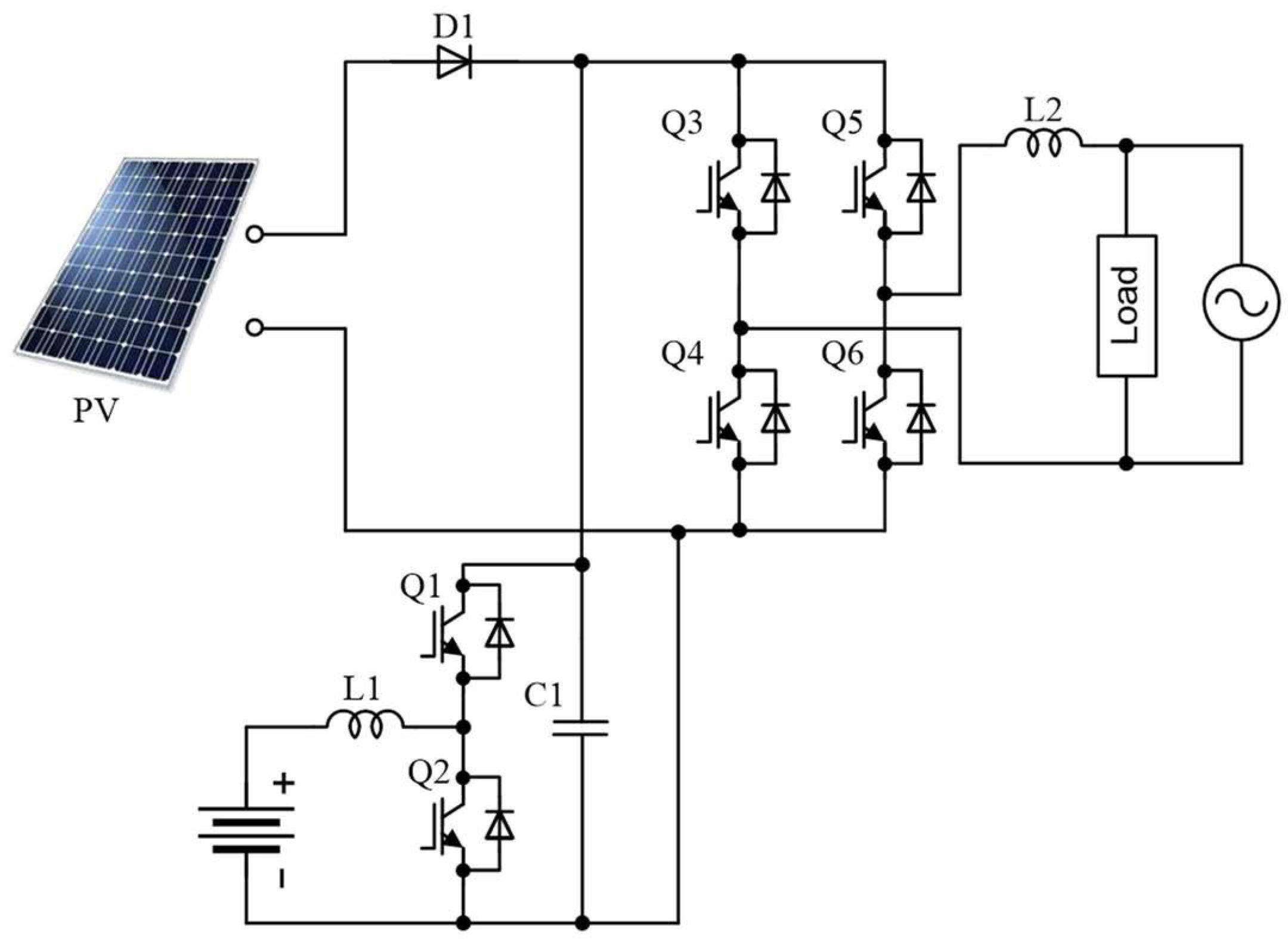
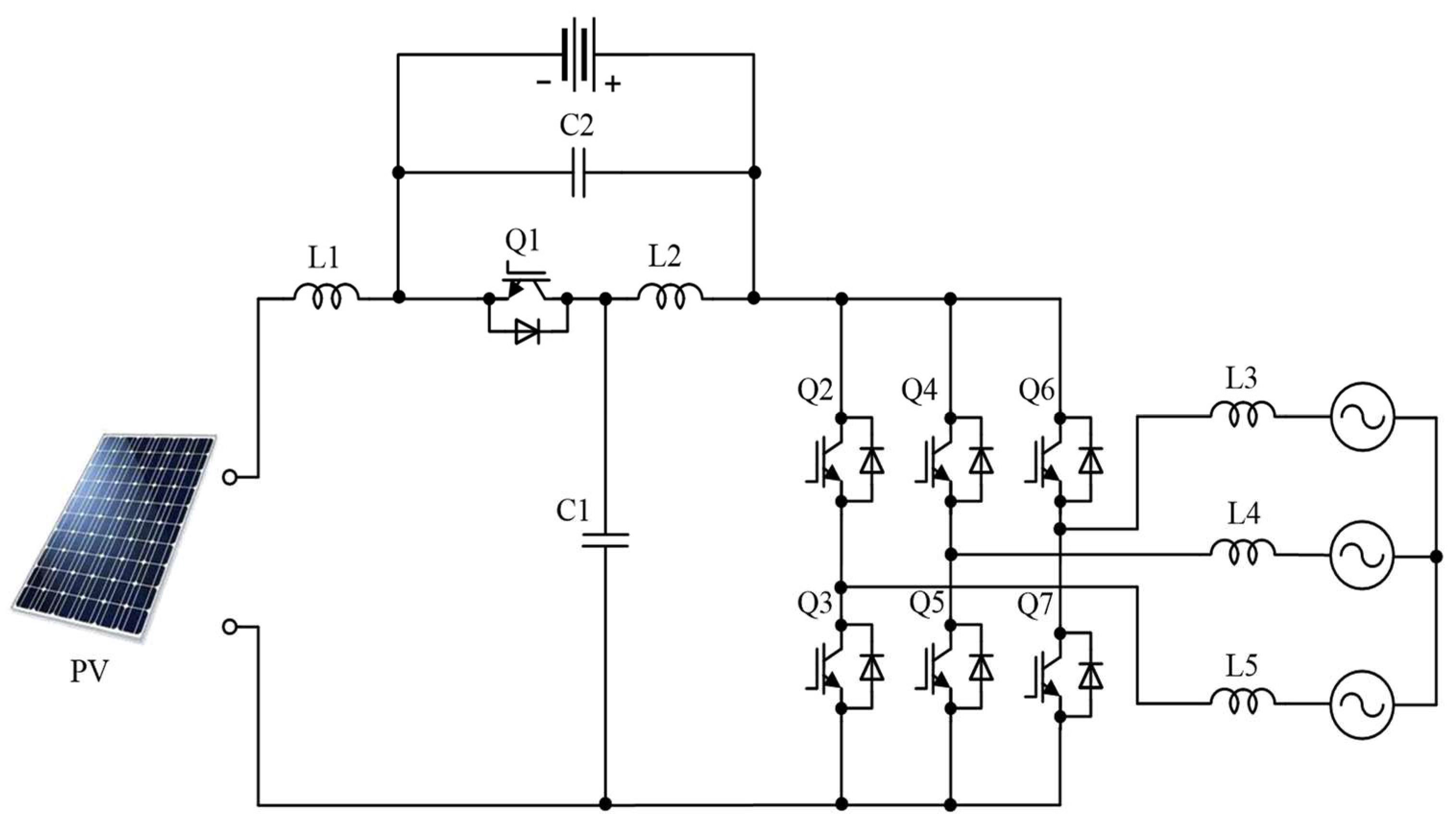
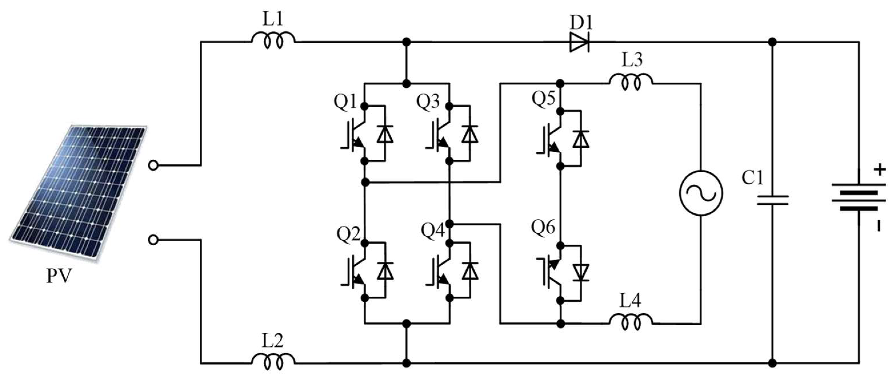
5.5. Hybrid Transformerless PV Converter

The hybrid transformerless PV converter is discussed in [65]. This system has one ac and two dc outputs. In this case, the inductor of the conventional boost converter is split into two symmetrical ones placed at the positive and negative dc rails, as shown in Figure 12. In addition, the switch of the conventional boost converter is replaced with a transformerless VSI.

6. Overview of the Isolated Multi-Port Converters

In this section, isolated converter topologies are discussed. Isolated multiport converters involving galvanic isolation between different ports have been introduced in several papers [66,67,68,69,70,71]. The use of a high-frequency transformer ensures isolation. Most of the topologies have been derived from conventional full-bridge or half-bridge dc-dc converters.

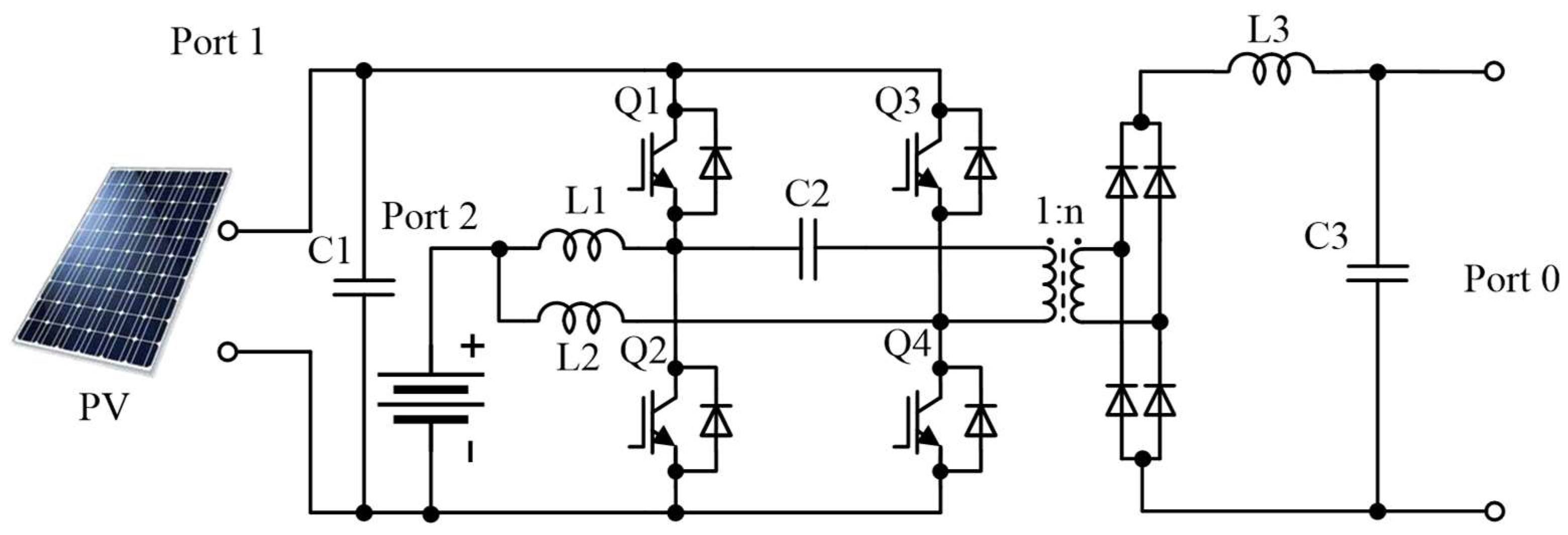
6.1. Symmetric Boost Integrated Phase Shift Converter

The topology of a three-port partially isolated converter is shown in Figure 13 and discussed in [72]. Ports 1 and 2 are inherently bidirectional. This means that each port can source or sink average power depending on the state of the converter and connected devices. Port 0 is unidirectional due to the use of diode rectifiers. The main power source is connected to port 0, and the battery is connected to port 2. Switch Q2 is driven complimentary to Q1 and switch Q4 is driven complimentary to Q3 with a short dead time in between. The power delivered to the load is controlled by controlling the phase shift between the gating signals of switches Q1 and Q3, and by controlling the duty ratio of the switches Q1 and Q3, which are required to be the same.

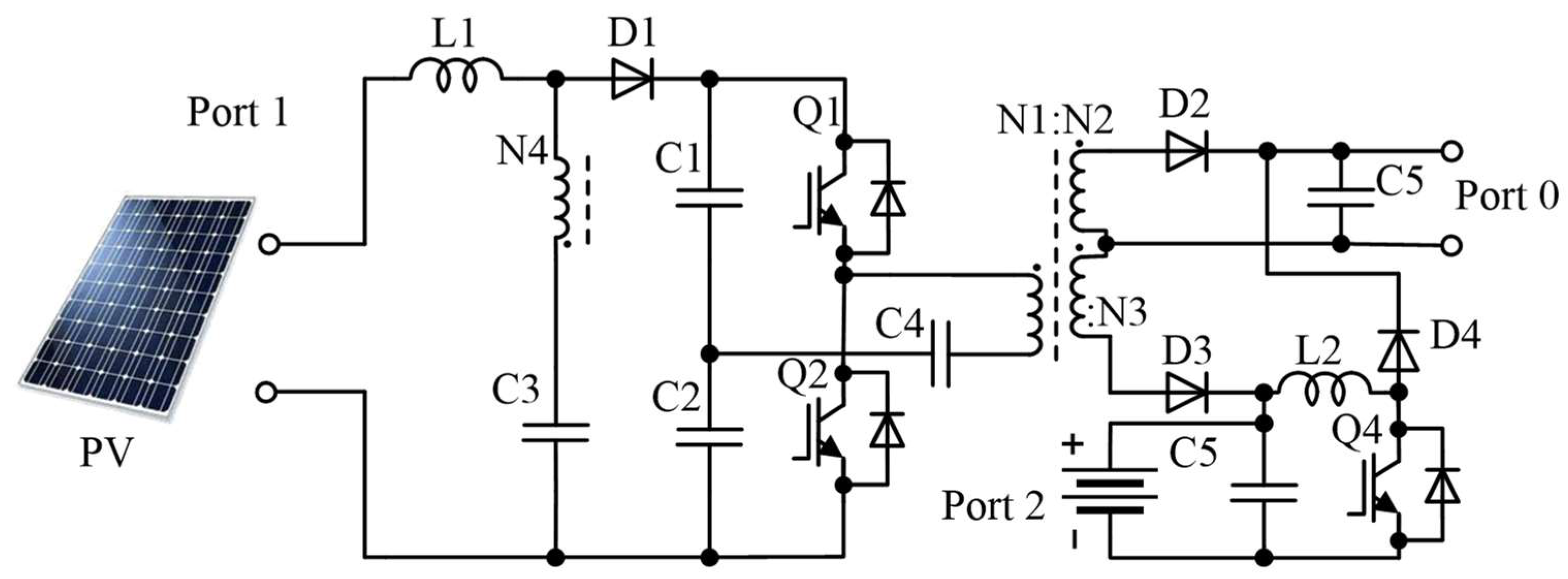
6.2. PV-Partially Isolated Three-Port Converter

A three-port partially isolated converter is shown in Figure 14 and discussed in [73]. The PV array is connected to port 1, the battery is connected to port 2, and port 0 is the load port. This converter has three operational modes: single input, dual output mode (PV to dc bus and battery), dual input, single output mode (PV and battery to dc bus), and single input, single output mode (battery to dc bus).

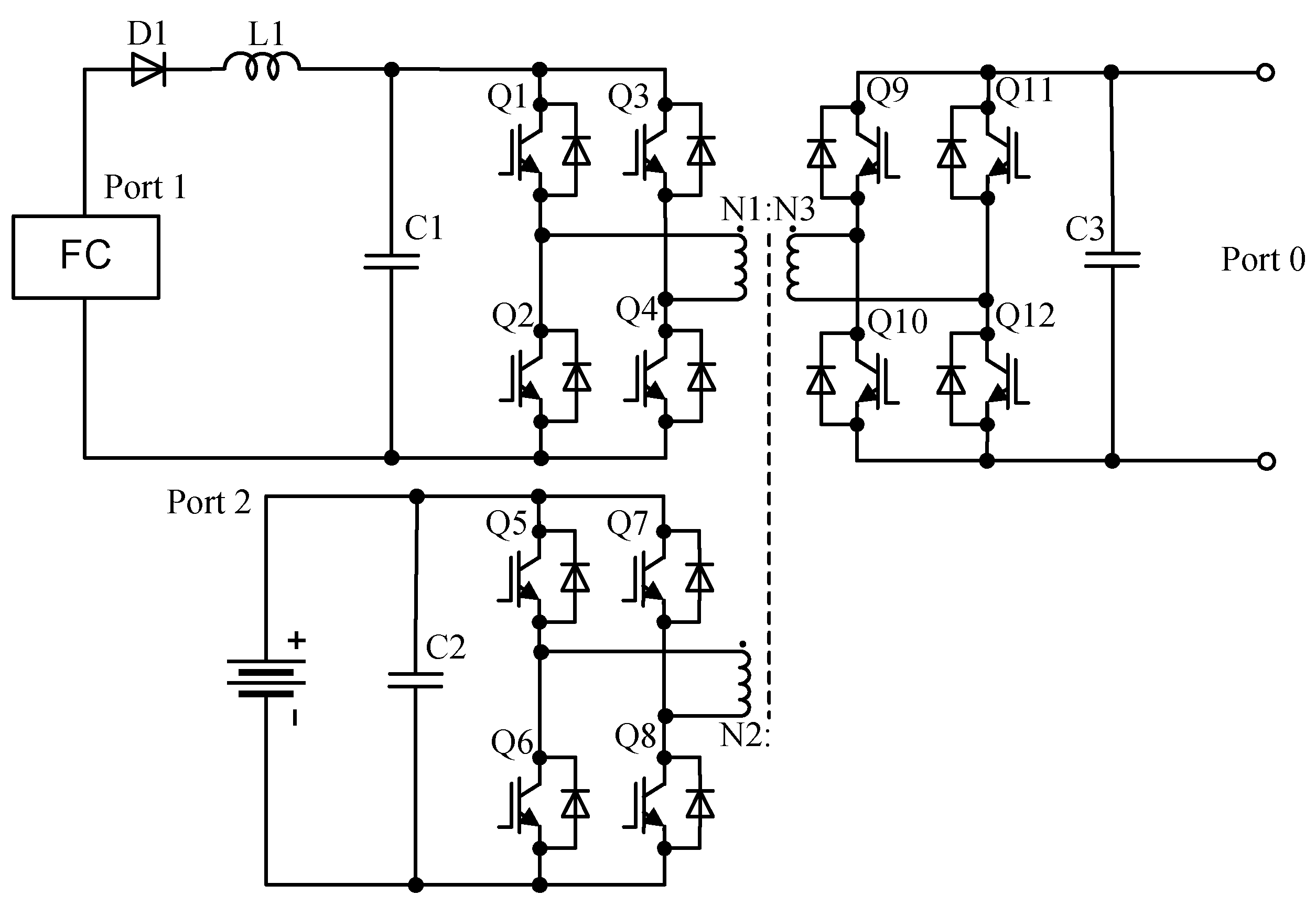
6.3. Fully Isolated Three-Port Converter

A three-port fully isolated converter is shown in Figure 15 and discussed in [73]. These modular systems have multiple modules. Each module has three ports, one fuel cell port, one energy storage port, and one load port, and all of these ports are bidirectional. The fuel cell port should be protected from reverse current, and diode D1 is used in this case for that purpose. Inductor L1 is used to mitigate current ripples. The phase shift between the active bridge interfacing port 1 and the active bridge interfacing port 0 is used to control the power flow.

6.4. Multiport CLL-Resonant Converter

A three-port fully isolated converter is shown in Figure 16 and discussed in [75]. Port 1 is the main input port, port 2 is an auxiliary input port, and port 0 is the load port. The phase shift between the two input ports is used to control the output voltage.
The phase shift between the two input ports is maintained at 90°. In the paper, this converter is modeled as a square wave voltage source and the transformer is modeled with its equivalent T model.
A summary of the hybrid solutions discussed above is presented in Table 2. The table illustrates the number of components, power rating, and insulation, as well as electrical features. L and C represent the number of inductors and capacitors, respectively.
Despite the many benefits provided by hybrid converters, there are some technical challenges that still need to be resolved to accelerate their practical feasibility. Future trends that should be followed by researchers in order to develop efficient hybrid converters are as follows:
  • Derived hybrid converters can be further improved to reduce the number and size of electrical components such as semiconductors, passive elements, etc. This will result in a reduction in the cost of manufacturing converters as well as their size.
  • Derived hybrid converters can be improved to reduce power conversion stages, which will reduce the total loss of the system.
  • Improved controllers can be designed in order to reduce switching complexity.
  • The power quality factors create a major problem when integrating the renewable energy system with the grid. Therefore, hybrid converters should be developed to take care of these power quality issues.
  • In order to enhance the performance of the power electronics converters, various improved switches should be developed, such as GaN-based switches. Therefore, while designing new hybrid converters, improved semiconductor devices must be employed to augment the performance of the system.

7. Conclusions

This paper presents a review of hybrid converter topologies. It is intended as a convenient reference for engineers. The main goal of this work was to analyze possible internal power electronics configurations that can be utilized inside commercial solutions.
The paper presents a review of significant commercially available single-phase and three-phase hybrid solar inverters. The review shows that the maximum input voltage range differs between different manufacturers and starts from 480 V and goes up to 1000 V. The MPPT voltage range also varies depending on the manufacturer. At the same time, the battery input voltage range is significantly smaller as is battery power.
The review also shows that most solutions are built based on a configuration consisting of a boost converter and VSI, while a bidirectional dc-dc converter provides power exchange between the battery and a common dc-link. Furthermore, solutions can be divided into isolated (have an isolated battery and/or load) and non-isolated. In addition, many different and more complex solutions have been proposed that are doubtful for practical utilization.

Author Contributions

Conceptualization, H.A. and O.H.; methodology investigation, and writing, H.A. and O.H.; validation, H.A., O.H., O.M. and D.V.; formal analysis, H.A., O.H. and O.M.; investigation, H.A.; resources, H.A. and O.H.; writing—original draft preparation, O.H. and H.A.; writing—review and editing, H.A.; visualization, H.A.; supervision, O.H. and D.V. All authors have read and agreed to the published version of the manuscript.

Funding

This work was supported by the Estonian Research Council grant PRG675 and by the Estonian Centre of Excellence in Zero Energy and Resource Efficient Smart Buildings and Districts (ZEBE).

Data Availability Statement

The data used in this study is publicly available and sources are referred.

Conflicts of Interest

The authors declare no conflict of interest related to the study.

References

  1. Ilić, M.D.; Zaborszky, J. Electric power systems engineering. In Encyclopedia of Energy; Elsevier: Amsterdam, The Netherlands; Academic Press: Boston, MA, USA, 2004; Volume 2, pp. 267–287. [Google Scholar]
  2. Blaabjerg, F.; Chen, Z.; Kjaer, S.B. Power electronics as efficient interface in dispersed power generation systems. IEEE Trans. Power Electron. 2004, 19, 1184–1194. [Google Scholar] [CrossRef]
  3. Lai, J.S.H.; Nelson, D.J. Energy Management Power Converters in Hybrid Electric and Fuel Cell Vehicles. Proc. IEEE 2007, 95, 766–777. [Google Scholar] [CrossRef]
  4. Boroyevich, D.; Cvefkovic, L.; Dong, D.; Burgos, R.; Wang, F.; Lee, F. Future electronic power distribution systems-A contemplative view. In Proceedings of the 12th International conference OPTIM Electrical and Electronic Equipment, Brasov, Romania, 20–22 May 2010; pp. 1369–1380. [Google Scholar]
  5. Adda, R.; Ray, O.; Mishra, S.K.; Joshi, A. Synchronous-Reference-Frame-Based Control of Switched Boost Inverter for Standalone DC Nanogrid Applications. IEEE Trans. Power Electron. 2013, 28, 1219–1233. [Google Scholar] [CrossRef]
  6. Nag, S.S.; Adda, R.; Ray, O.; Mishra, S.K. Current-Fed Switched Inverter based hybrid topology for DC Nanogrid application. In Proceedings of the IEEE 39th Annual Conference of the Industrial Electronics Society, Vienna, Austria, 10–13 November 2013; pp. 7146–7151. [Google Scholar]
  7. Ravindranath, A.; Mishra, S.K.; Joshi, A. Analysis and PWM Control of Switched Boost Inverter. IEEE Trans. Ind. Electron. 2013, 60, 5593–5602. [Google Scholar] [CrossRef]
  8. Ray, O.; Mishra, S. Boost-Derived Hybrid Converter with simultaneous DC and AC outputs. IEEE Trans. Ind. Appl. 2014, 50, 1082–1093. [Google Scholar] [CrossRef]
  9. Ray, O.; Mishra, S. Constant-frequency shoot-through sine pulse-width-modulation scheme for three-phase single-input–hybrid-output converter. IET Power Electron. 2016, 9, 1819–1827. [Google Scholar] [CrossRef]
  10. Sharma, A.; Pramod, B.; Singh, R.K.; Mahanty, R. Interleaved hybrid boost converter with simultaneous DC and AC outputs for micro-source applications. In Proceedings of the IEEE Energy Conversion Congress and Exposition (ECCE), Milwaukee, WI, USA, 18–22 September 2016; pp. 1–8. [Google Scholar]
  11. Bhattacharjee, A.K.; Kutkut, N.; Batarseh, I. Review of Multiport Converters for Solar and Energy Storage Integration. IEEE Trans. Power Electron. 2019, 34, 1431–1445. [Google Scholar] [CrossRef]
  12. Affam, A.; Buswig, Y.M.; Othman, A.K.B.H.; Julai, N.B.; Qays, O. A review of multiple input DC-DC converter topologies linked with hybrid electric vehicles and renewable energy systems. Renew. Sustain. Energy Rev. 2021, 135, 110186. [Google Scholar] [CrossRef]
  13. Raju, N.; Mohan, N.M.; Kumar, V. A Review of Extended Voltage Range DC-DC Converter Topologies. In Intelligent Computing & Optimization. Lecture Notes in Networks and Systems; Vasant, P., Weber, G.W., Marmolejo-Saucedo, J.A., Munapo, E., Thomas, J.J., Eds.; Springer: Cham, NY, USA, 2022; Volume 569. [Google Scholar]
  14. Sonia, B.; Venkata Lakshmi, V.; Varas Prasad, M.V.G. Boost Derived Multi Level Hybrid Converters in Micro Grid. In Smart Energy and Advancement in Power Technologies. Lecture Notes in Electrical Engineering; Namrata, K., Priyadarshi, N., Bansal, R.C., Kumar, J., Eds.; Springer: Singapore, 2023; Volume 927. [Google Scholar]
  15. Edson, H.W.; Gilson, S., Jr. Flexible AC Transmission Systems. In Power Electronics Handbook: Devices, Circuits and Applications (Engineering); Academic Press: Cambridge, MA, USA, 2018. [Google Scholar]
  16. Hirst, E.; Kirby, B. Electric-Power Ancillary Services. ORNL/CON-426; Oak Ridge National Laboratory: Oak Ridge, TN, USA, 1996.
  17. Pagano, E.; Piegari, L.; Tricoli, P. Approaches to analytical analysis of active filter behaviour. In Proceedings of the 29th Annual Conference of the IEEE Industrial Electronics Society IECON’03, Roanoke, VA, USA, 2–6 November 2003; Volume 3, pp. 2003–2022. [Google Scholar]
  18. D’Arco, S.; Iannuzzi, D.; Pagano, E.; Tricoli, P. Analysis of active filter behaviour by means of modified z-transform method. IEE Proc. Electric Power Applications. 2005, 152, 695–702. [Google Scholar] [CrossRef]
  19. Yang, B.; Li, W.; Zhao, Y.; He, X. Design and Analysis of a Grid-Connected Photovoltaic Power System. IEEE Trans. Power Electron. 2010, 25, 992–1000. [Google Scholar] [CrossRef]
  20. Pereira, H.; Domingos, R.; Xavier, L.; Cupertino, A.; Mendes, V.; Paulino, J. Adaptive saturation for a multifunctional three-phase photovoltaic inverter. In Proceedings of the 17th European Conference on Power Electronics and Applications, Geneva, Switzerland, 29 October 2015; pp. 1–10. [Google Scholar]
  21. He, J.; Li, Y.W.; Munir, M.S. A flexible harmonic control approach through voltage-controlled DG–Grid interfacing converters. IEEE Trans. Ind. Electron. 2012, 59, 444–455. [Google Scholar] [CrossRef]
  22. Narinder, K.; Trehan, P.E. Ancillary Services- Reactive and Voltage Control. Power Eng. Soc. Winter Meet. 2001, 3, 1341–1346. [Google Scholar]
  23. Svarc, J. Hybrid Inverter Comparison Chart. Available online: https://www.cleanenergyreviews.info/hybrid-solar-inverter-comparison (accessed on 26 November 2022).
  24. Ev Charching Single Phase Inverter. Available online: https://www.europe-solarstore.com/download/solaredge/solaredge_3680-6000h_hd-wave_setapp_integrated_ev_charger_en.pdf (accessed on 26 November 2022).
  25. LG Energy Solutions. Available online: https://www.europe-solarstore.com/download/lgchem/LG_Chem_RESU_datasheet.pdf (accessed on 26 November 2022).
  26. FRONIUS SYMO HYBRID. Available online: https://www.europe-solarstore.com/download/fronius/solarbattery/DS_Fronius_Energy_Package_EN_386411_snapshot.pdf (accessed on 26 November 2022).
  27. Smart Energy Controller. Available online: https://solar.huawei.com/en-GB/download?p=%2F %2Fmedia%2FSolar%2Fattachment%2Fpdf%2Feu%2Fdatasheet%2FSUN2000-2-6KTL-L1.pdf (accessed on 26 November 2022).
  28. Power Conversion System/Hybrid Inverter. Available online: https://uk.sungrowpower.com/upload/file/20210723/EN%20DS%20SH5.0RT%206.0RT%208.0RT%2010RT%20Datasheet.pdf (accessed on 26 November 2022).
  29. Power Conversion System/Hybrid Inverter. Available online: https://www.sungrowpower.com/sites/default/files/SBP4K8-UEN-Ver14-201807.pdf (accessed on 10 June 2021).
  30. ABB PV + Storage. Available online: https://www.rectifier.co.za/wp-content/uploads/2019/08/REACT2-3.6-5.0-TL_BCD.00688_EN_RevD.pdf (accessed on 26 November 2022).
  31. Redback SH5000 Hybrid Solar-Battery Inverter-Charger Inverter. Available online: https://www.ecocool.com.au/products/inverters/redback-sh5000-hybrid-solar-battery-inverter-charger-inverter (accessed on 26 November 2022).
  32. Solis High Voltage Energy Storage Inverters. Available online: https://www.invertersupply.com/media/data/Datasheet_RHI-1P5K-HVES-5G.pdf (accessed on 26 November 2022).
  33. Self Consumption Solar Hybrid Inverters. Available online: https://imeon-energy.com/wp-content/uploads/datasheet-imeon-hybrid-solar-inverter.pdf (accessed on 26 November 2022).
  34. X1-HYBRID HV/X3-HYBRID HV. Available online: https://www.solaxpower.com/wp-content/uploads/2017/01/X-Hybrid-SingleThree-Phase-Datasheet.pdf (accessed on 26 November 2022).
  35. Hybrid Converter. Available online: https://files.sma.de/downloads/SBS37-60-DAU1902-V21web.pdf (accessed on 10 June 2021).
  36. Afshari, H.; Husev, O.; Vinnikov, D.; Matiushkin, O.; Vosoughi KurdKandi, N. Comparison of Grid-Connected Flyback-based Microinverter with Primary and Secondary Side Decoupling Approach. In Proceedings of the IEEE 63rd International Scientific Conference on Power and Electrical Engineering of Riga Technical University (RTUCON), Riga, Latvia, 10 October 2022. [Google Scholar]
  37. Vega Garita, V.; Garg, S.; Narayan, N.; Ramirez Elizondo, L.; Bauer, P. Testing a PV-battery Integrated Module Prototype. In Proceedings of the 2018 IEEE 7th World Conference on Photovoltaic Energy Conversion (WCPEC) (A Joint Conference of 45th IEEE PVSC, 28th PVSEC & 34th EU PVSEC), Waikoloa, HI, USA, 10–15 June 2018. [Google Scholar]
  38. Vega Garita, V.; Garg, S.; Narayan, N.; Ramirez Elizondo, L.; Bauer, P. PV-battery integrated module as a solution for off-grid applications in the developing world. In Proceedings of the 2018 IEEE International Energy Conference (ENERGYCON), Limassol, Cyprus, 3–7 June 2018. [Google Scholar]
  39. Nahavandi, A.; Hagh, M.T.; Sharifian, M.B.; Danyali, S. A nonisolated multiinput multioutput dc–dc boostconverter for electric vehicle applications. IEEE Trans. Power Electron. 2015, 30, 1818–1835. [Google Scholar] [CrossRef]
  40. Gummi, K.; Ferdowsi, M. Double-Input DC–DC Power Electronic Converters for Electric-Drive Vehicles—Topology Exploration and Synthesis Using a Single-Pole Triple-Throw Switch. IEEE Trans. Ind. Electron. 2010, 57, 617–623. [Google Scholar] [CrossRef]
  41. Solero, L.; Lidozzi, A.; Pomilio, J.A. Design of multiple-input power converter for hybrid vehicles. IEEE Trans. Power Electron. 2005, 20, 1007–1016. [Google Scholar] [CrossRef]
  42. Hintz, A.; Prasanna, U.R.; Rajashekara, K. Novel Modular Multiple-Input Bidirectional DC–DC Power Converter (MIPC) for HEV/FCV Application. IEEE Trans. Ind. Electron. 2015, 62, 3163–3172. [Google Scholar] [CrossRef]
  43. Yang, P.; Tse, C.K.; Xu, J.; Zhou, G. Synthesis and Analysis of Double-Input Single-Output DC/DC Converters. IEEE Trans. Ind. Electron. 2015, 62, 6284–6295. [Google Scholar] [CrossRef]
  44. Nagata, H.; Uno, M. Multi-port converter integrating two PWM converters for multi-power-source systems. In Proceedings of the IEEE 3rd International Future Energy Electronics Conference and ECCE, Taiwan, China, 3–7 June 2017; pp. 1833–1838. [Google Scholar]
  45. Zhu, H.; Zhang, D.; Zhang, B.; Zhou, Z. A Non-Isolated Three-Port DC–DC Converter and Three-Domain Control Method for PV-Battery Power Systems. IEEE Trans. Ind. Electron. 2015, 62, 4937–4947. [Google Scholar] [CrossRef]
  46. Marchesoni, M.; Vacca, C. New DC–DC Converter for Energy Storage System Interfacing in Fuel Cell Hybrid Electric Vehicles. IEEE Trans. Power Electron. 2007, 22, 301–308. [Google Scholar] [CrossRef]
  47. Zhu, H.; Zhang, D.; Liu, Q.; Zhou, Z. Three-Port DC/DC Converter with All Ports Current Ripple Cancellation Using Integrated Magnetic Technique. IEEE Trans. Power Electron. 2016, 31, 2174–2186. [Google Scholar] [CrossRef]
  48. Chiang, S.J.; Chang, K.T.; Yen, C.Y. Residential photovoltaic energy storage system. IEEE Trans. Ind. Electron. 1998, 45, 385–394. [Google Scholar] [CrossRef]
  49. Ding, F.; Li, P.; Huang, B.; Gao, F.; Ding, C.; Wang, C. Modeling, and simulation of grid-connected hybrid photovoltaic/battery distributed generation system. In Proceedings of the CICED 2010 Proceedings, Nanjing, China, 13–16 September 2010; pp. 1–10. [Google Scholar]
  50. Gurkaynak, Y.; Li, Z.; Khaligh, A. A novel grid-tied, solar powered residential home with plug-in hybrid electric vehicle (PHEV) loads. In Proceedings of the IEEE Vehicle Power and Propulsion Conference, Dearborn, MI, USA, 7–11 September 2009; pp. 813–816. [Google Scholar]
  51. Jayasinghe, S.D.G.; Vilathgamuwa, D.M.; Madawala, U.K. Diode-Clamped Three-Level Inverter-Based Battery/Supercapacitor Direct Integration Scheme for Renewable Energy Systems. IEEE Trans. Power Electron. 2011, 26, 3720–3729. [Google Scholar] [CrossRef]
  52. Stepenko, S.; Husev, O.; Pimentel, S.P.; Makovenko, E.; Vinnikov, D. Small Signal Modeling of Interleaved Quasi-Z-Source Inverter with Active Power Decoupling Circuit. In Proceedings of the IEEE 59th International Scientific Conference on Power and Electrical Engineering of Riga Technical University (RTUCON), Riga, Latvia, 12–14 November 2018; pp. 1–6. [Google Scholar]
  53. Zheng Peng, F. Z-source inverter. IEEE Trans. Ind. Electron. 2003, 39, 504–510. [Google Scholar] [CrossRef]
  54. Liu, Y.; Abu Rub, H.; Ge, B. Z-Source/Quasi-Z-Source Inverters: Derived Networks, Modulations, Controls, and Emerging Applications to Photovoltaic Conversion. IEEE Ind. Electron. Mag. 2014, 8, 32–44. [Google Scholar] [CrossRef]
  55. Ellabban, O.; Abu-Rub, H. Z-Source Inverter: Topology Improvements Review. IEEE Ind. Electron. Mag. 2016, 10, 6–24. [Google Scholar] [CrossRef]
  56. Holland, K.; Shen, M.; Peng, F.Z. Z-source inverter control for traction drive of fuel cell—Battery hybrid vehicles. In Proceedings of the Fourtieth IAS Annual Meeting. Conference Record of the 2005 Industry Applications Conference, Hong Kong, China, 2–6 October 2005; Volume 3, pp. 1651–1656. [Google Scholar]
  57. Sun, D.; Ge, B.; Peng, F.Z.; Abu Rub, H.; De Almeida, A.T. Power flow control for quasi-Z source inverter with battery-based PV power generation system. In Proceedings of the IEEE Energy Conversion Congress and Exposition, Phoenix, AZ, USA, 17–22 September 2011; pp. 1051–1056. [Google Scholar]
  58. Khajesalehi, J.; Sheshyekani, K.; Hamzeh, M.; Afjei, E. High-performance hybrid photovoltaic-battery system based on quasi-Z-source inverter: Application in microgrids. IET Gener. Transm. Distrib. 2015, 9, 895–902. [Google Scholar] [CrossRef]
  59. Vinnikov, D.; Chub, A.; Liivik, E.; Kosenko, R.; Korkh, O. Solar Optiverter—A Novel Hybrid Approach to the Photovoltaic Module Level Power Electronics. IEEE Trans. Ind. Electron. 2019, 66, 3869–3880. [Google Scholar] [CrossRef]
  60. Husev, O.; Vinnikov, D.; Roncero-Clemente, C.; Chub, A.; Romero-Cadaval, E. Single-Phase String Solar qZS-based Inverter: Example of Multi-Objective Optimization Design. IEEE Trans. Ind. Appl. 2021, 57, 3120–3130. [Google Scholar] [CrossRef]
  61. Husev, O.; Shults, T.; Vinnikov, D.; Roncero-Clemente, C.; Romero-Cadaval, E.; Chub, A. Comprehensive Comparative Analysis of Impedance-Source Networks for DC and AC Application. Electronics 2019, 8, 405. [Google Scholar] [CrossRef] [Green Version]
  62. Panfilov, D.; Husev, O.; Blaabjerg, F.; Zakis, J.; Khandakji, K. Comparison of three-phase three-level voltage source inverter with intermediate dc–dc boost converter and quasi-Z-source inverter. IET Power Electron. 2016, 9, 1238–1248. [Google Scholar] [CrossRef]
  63. Wolski, K.; Zdanowski, M.; Rabkowski, J. High-Frequency SiC-Based Inverters with Input Stages Based on Quasi-Z-Source and Boost Topologies—Experimental Comparison. IEEE Trans. Power Electron. 2019, 34, 9471–9478. [Google Scholar] [CrossRef]
  64. Kroics, K.; Zakis, J.; Suzdalenko, A.; Husev, O.; Tytelmaier, K.; Khandakji, K. Operation possibility of grid connected Quasi-Z-Source Inverter with energy storage and renewable energy generation in wide power range. In Proceedings of the IEEE First Ukraine Conference on Electrical and Computer Engineering (UKRCON), Kyiv, Ukraine, 29 May–2 June 2017; pp. 564–569. [Google Scholar]
  65. Zhongting, T.; Yang, Y.; Wan, J.; Blaabjerg, F. Hybrid transformerless PV converters with low leakage currents: Analysis and configuration. IET Renew. Power Gener. 2021, 15, 368–381. [Google Scholar]
  66. Y-S, L.; Y-P, K. Switched-capacitor bi-directional converter performance comparison with and without quasi-resonant zero-current switching. IET Power Electron. 2010, 3, 269–278. [Google Scholar]
  67. Zhao, C.; Round, S.D.; Kolar, J.W. An Isolated Three-Port Bidirectional DC-DC Converter with Decoupled Power Flow Management. IEEE Trans. Power Electron. 2008, 23, 2443–2453. [Google Scholar] [CrossRef]
  68. Tao, H.; Kotsopoulos, A.; Duarte, J.L.; Hendrix, M.A.M. Transformer-Coupled Multiport ZVS Bidirectional DC–DC Converter with Wide Input Range. IEEE Trans. Power Electron. 2008, 23, 771–781. [Google Scholar] [CrossRef]
  69. Das, P.; Laan, B.; Mousavi, S.A.; Moschopoulos, G. A Nonisolated Bidirectional ZVS-PWM Active Clamped DC–DC Converter. IEEE Trans. Power Electron. 2009, 24, 553–558. [Google Scholar]
  70. Duan, R.Y.; Lee, J.D. High-efficiency bidirectional DC-DC converter with coupled inductor. IET Power Electron. 2012, 5, 115–123. [Google Scholar] [CrossRef]
  71. Ahmadi, M.; Mohammadi, M.R.; Adib, E.; Farzanehfard, H. Family of non-isolated zero current transition bi-directional converters with one auxiliary switch. IET Power Electron. 2012, 5, 158–165. [Google Scholar] [CrossRef]
  72. Al-Atrash, H.; Batarseh, I. Boost-Integrated Phase-Shift Full-Bridge Converter for Three-Port Interface. In Proceedings of the IEEE Power Electronics Specialists Conference, Orlando, FL, USA, 17–21 June 2007; pp. 2313–2321. [Google Scholar]
  73. Zhu, H.; Zhang, D.; Athab, H.S.; Wu, B.; Gu, Y. PV Isolated Three-Port Converter and Energy-Balancing Control Method for PV-Battery Power Supply Applications. IEEE Trans. Ind. Electron. 2015, 62, 3595–3606. [Google Scholar] [CrossRef]
  74. Phattanasak, M.; Gavagsaz Ghoachani, R.; Martin, J.P.; Nahid Mobarakeh, B.; Pierfederici, S.; Davat, B. Control of a Hybrid Energy Source Comprising a Fuel Cell and Two Storage Devices Using Isolated Three-Port Bidirectional DC–DC Converters. IEEE Trans. Ind. Appl. 2015, 51, 491–497. [Google Scholar] [CrossRef]
  75. Asa, E.; Colak, K.; Bojarski, M.; Czarkowski, D. Asymmetrical Duty-Cycle and Phase-Shift Control of a Novel Multiport CLL Resonant Converter. IEEE J. Emerg. Sel. Top. Power Electron. 2015, 3, 1122–1131. [Google Scholar] [CrossRef]
Figure 1. Schematic diagram of a solar energy system: without (a) and with (b) battery storage assistance.
Energies 15 09341 g001
Figure 2. On-grid general mode: PV power is sufficient (a), PV power is insufficient (b).
Energies 15 09341 g002
Figure 3. On-grid with battery backup mode: PV power is sufficient (a), PV power is insufficient (b), when a grid fault occurs (c).
Energies 15 09341 g003
Figure 4. Off-grid mode: PV power is sufficient (a), PV power is insufficient (b).
Energies 15 09341 g004
Figure 5. Typical structures of hybrid solar inverters. The battery connected directly to the dc-link (a), The battery integrated into the Energy Storage Systems and connected to dc-link (ESS) (b), the integrated battery interface connected to the dc low voltage (c), the integrated battery interface connected to the ac voltage (d).
Energies 15 09341 g005
Figure 6. Battery link MPC with PV boost converter [48].
Energies 15 09341 g006
Figure 7. Dc bus MPC with boost-boost converters [49].
Energies 15 09341 g007
Figure 8. DC Bus MPC with battery boost converter [50].
Energies 15 09341 g008
Figure 9. Diode-Clamped Multi-Port Converter [51].
Energies 15 09341 g009
Figure 10. ZS-MPC [56].
Energies 15 09341 g010
Figure 11. qZS-MPC with Battery Storage Paralleling an Upper Capacitor [57].
Energies 15 09341 g011
Figure 12. Hybrid Transformerless PV Converter [65].
Energies 15 09341 g012
Figure 13. Symmetric Boost Integrated Phase Shift Converter [72].
Energies 15 09341 g013
Figure 14. PV-Partially Isolated Three-Port Converter [73].
Energies 15 09341 g014
Figure 15. Isolated Three-Port Bi-Directional DC-DC Converter [74].
Energies 15 09341 g015
Figure 16. Isolated Three-Port CLL- Resonant Converter [75].
Energies 15 09341 g016
Table 1. Table of commercial hybrid inverters.
DeviceNominal AC Power, WMax. Efficiency, %Number of PhasesBattery TypeBattery Voltage Range, VMax. Battery Power, WBattery CommunicationComments
1Huawei SUN2000
-5KTL-L1 [27]
500097.81Li-ion350–450 5000RS485Battery is connected to dc-link
2Fronius SYMO Hybrid 5.0-3-S [26]5000963LiFePO4240–345 4800RS485Different battery packs can be used (BATTERY 9.0 is shown)
3Sungrow SH5K-30 [28]500097.11Li-ion32–70 4500CAN/
RS485
4Redback SH5000 [31]5000971Li-ion42–60 4600CAN
5ABB REACT2-UNO-5.0-TL [30]500096.61Li-ion170–575 5000RS485
6Solis RHI-1P5K-HVES-5G [32]500097.51Li-ion120–5007000CAN/
RS485
Continuous maximum battery power is 6 kW
7Imeon 3.6 [33]300094.51Li-ion42–62 3840RS485
8SolaX X3 Hybrid 5.0 T [34]5000973Li-ion200–500 5000CAN/
RS485
9Sunny Boy Storage 5.0 [35]500097.51Li-ion100–5505000CAN/
RS485
Table 2. Summary of hybrid solutions.
ReferencesNumber of ComponentsPower RatingsIsolationProsCons
Switch
& Diode
LC
Ref [48]623600 WNo
  • Conventional solution, low cost.
  • Limited range of battery voltage
Ref [50]7215 kWNo
  • Conventional solution, low cost.
  • Limited range of photovoltaic voltage
Ref [51]193110 kWNo
  • Possible improved power density
  • The inverter complexity, losses, limited range of photovoltaic voltage
Ref [57]75210 kWNO
  • Greater reliability
  • Complexity of the control and limited range of battery voltage, cannot work without photovoltaic input
Ref [65]7414.5 kWNo
  • Low leakage current
  • High efficiency
  • Limited range of battery and photovoltaic voltage, range
Ref [72]8335 kWYes
  • High-efficiency, isolated solution
  • Voltage Limitation
Ref [74]13 12 1 kWYes
  • Isolated solution
  • Voltage Limitation, not high efficiency
Ref [75]8 2 31 kWYes
  • Isolated solution
  • Simplicity, high efficiency
  • Voltage Limitation
Publisher’s Note: MDPI stays neutral with regard to jurisdictional claims in published maps and institutional affiliations.

