
Effect of Tube Bundle Arrangement on the Performance of PCM Heat Storage Units


Abstract
:1. Introduction
2. Materials and Methods
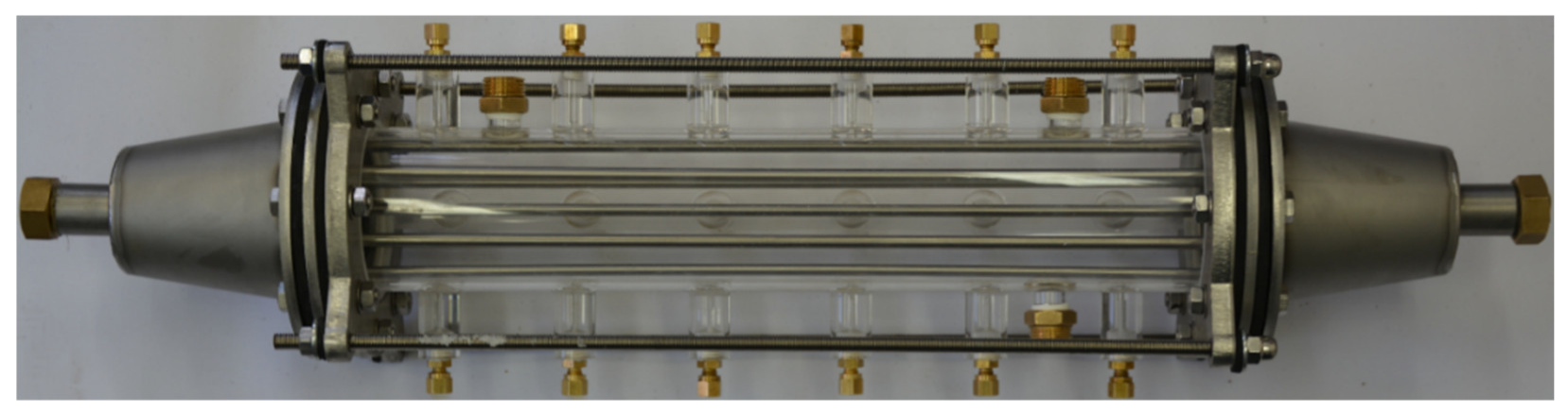
2.1. Tested LHSS
2.2. Materials
2.3. Experimental Procedure
2.4. Measurement Uncertainty
3. Results and Discussion
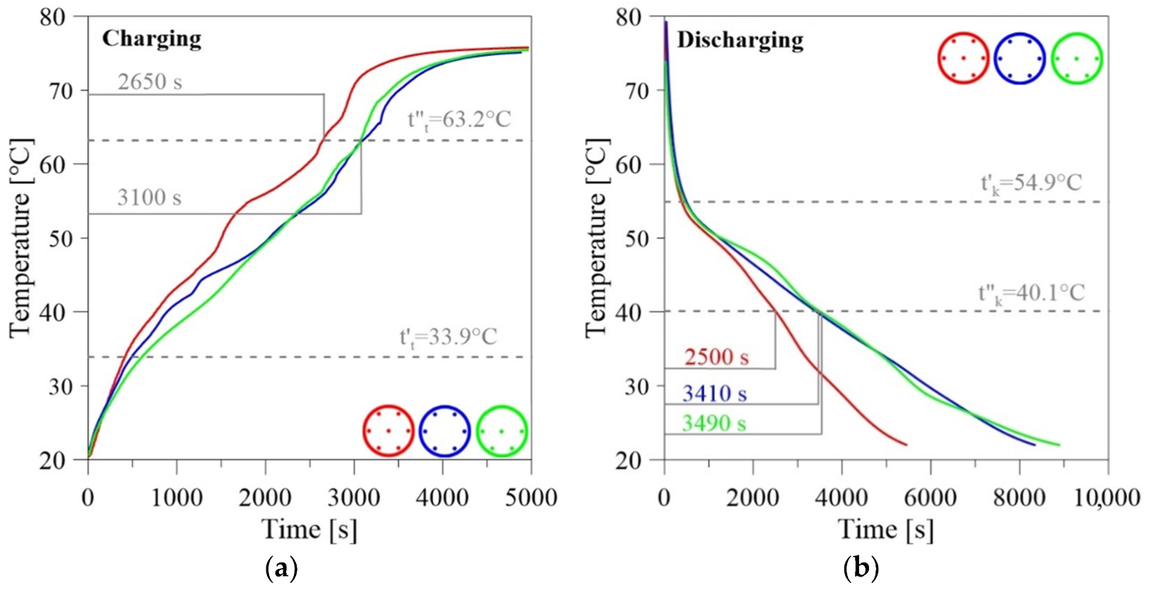
3.1. Effect of the Number of Tubes in A Bundle
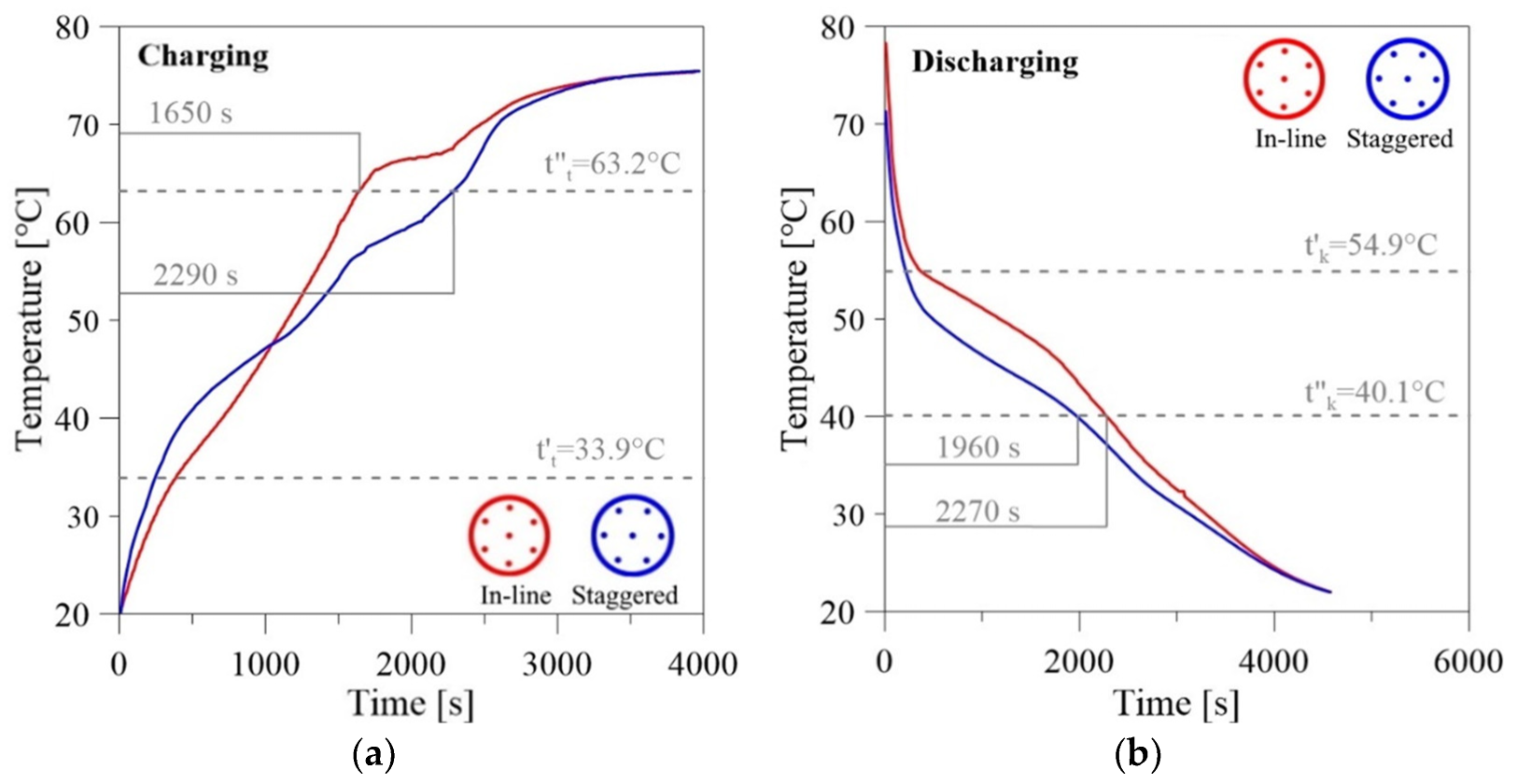
3.2. Effect of the Tube Arrangement
3.3. Effect of the Pitch Ratio
4. Conclusions
- Regardless of the tube layout, the shortest charging/discharging time was obtained for the bundle with the largest tested number of tubes, namely, seven.
- Studies have shown that in addition to increasing the number of tubes, and thus the heat transfer surface, the arrangement of the tubes is no less important. The centrally located tube is extremely important, as it affects the progress of both the melting and solidification processes.
- The staggered tube arrangement outperformed the in-line tube layout for the discharging process. For the charging process, the opposite is true.
- Out of the two pitch ratios tested, namely, s/d = 4.5 and s/d = 5, the smaller pitch ratio results in shorter charging and discharging times.
- The conclusions presented are for a small LHSS with only a few tubes. Further investigations, including numerical ones, are necessary for the much larger LHSSs with large numbers of tubes.
Author Contributions
Funding
Conflicts of Interest
Nomenclature
| cp | Specific heat at constant pressure | [J/(kgK)] |
| d | Tube diameter | (m) |
| r | Heat of phase transition | [J/kg] |
| s | Pitch | (m) |
| t | Temperature | (°C) |
Subscripts
| k | Solidification |
| l | Liquid |
| m | Phase change |
| s | Solid |
| t | Melting |
Superscripts
| c | Cooling |
| h | Heating |
| ‘ | Beginning |
| “ | End |
Abbreviations
| DSC | Digital Scanning Calorimetry |
| HTF | Heat Transfer Fluid |
| LHSS | Latent Heat Storage System |
| PCM | Phase Change Material |
| SHSS | Sensible Heat Storage System |
| TCES | Thermochemical Energy Storage |
References
- Letcher, T.M. Storing Energy with Special Reference to Renewable Energy Sources; Elsevier: Amsterdam, The Netherlands, 2016. [Google Scholar]
- Domański, R. Conversion and Accumulation of Energy. Selected Problems; Biblioteka Naukowa Instytutu Lotnictwa nr 54. Sieć Badawcza Łukasiewicz—IL: Warsaw, Poland, 2020. (In Polish) [Google Scholar]
- Cabeza, L.F. (Ed.) Advances in Thermal Energy Storage Systems: Methods and Applications; Woodhead Publishing Series in Energy; Elsevier: Amsterdam, The Netherlands, 2015. [Google Scholar]
- Faninger, G. Thermal Energy Storage. 2005. Available online: http://www.celsius.co.kr/phase_change_materials/download/energy/Thermal_Energy_Storage.pdf (accessed on 21 January 2016).
- Fredi, G.; Dorigato, A.; Fambri, L.; Pegoretti, A. Evaluating the multifunctional performance of structural composites for thermal energy storage. Polymers 2021, 13, 3108. [Google Scholar] [CrossRef] [PubMed]
- Khan, Z.; Khan, Z.; Ghafoor, A. A review of performance enhancement of PCM based latent heat storage system within the context of materials, thermal stability and compatibility. Energy Convers. Manag. 2016, 115, 132–158. [Google Scholar]
- Hendra, R.; Hamdani; Mahlia, T.M.I.; Masjuki, H.H. Thermal and melting heat transfer characteristics in a latent heat storage system using Mikro. Appl. Therm. Eng. 2005, 25, 1503–1515. [Google Scholar] [CrossRef]
- Trp, A. An experimental and numerical investigation of heat transfer during technical grade paraffin melting and solidification in a shell-and-tube latent thermal energy storage unit. Sol. Energy 2005, 79, 648–660. [Google Scholar] [CrossRef]
- Agyenim, F.; Eames, P.; Smyth, M. Heat transfer enhancement in medium temperature thermal energy storage system using a multitube heat transfer array. Renew. Energy 2010, 35, 198–207. [Google Scholar] [CrossRef]
- Kibria, M.A.; Anisur, M.R.; Mahfuz, M.H.; Saidur, R.; Metselaar, I.H.S.C. Numerical and experimental investigation of heat transfer in a shell and tube thermal energy storage system. Int. Commun. Heat Mass Transf. 2014, 53, 71–78. [Google Scholar]
- Esapour, M.; Hosseini, M.J.; Ranjbar, A.A.; Pahamli, Y.; Bahrampoury, R. Phase change in multi-tube heat exchangers. Renew. Energy 2016, 85, 1017–1025. [Google Scholar] [CrossRef]
- Tao, Y.B.; Carey, V.P. Effects of PCM thermophysical properties on thermal storage performance of a shell-and-tube latent heat storage unit. Appl. Energy 2016, 179, 203–210. [Google Scholar]
- Gasia, J.; Diriken, J.; Bourke, M.; Van Bael, J.; Cabeza, L.F. Comparative study of the thermal performance of four different shell-and-tube heat exchangers used as latent heat thermal energy storage systems. Renew. Energy 2017, 114, 934–944. [Google Scholar] [CrossRef]
- Han, G.S.; Ding, H.S.; Huang, Y.; Tong, L.G.; Ding, Y.L. A comparative study on the performances of different shell-and-tube type latent heat thermal energy storage units including the effects of natural convection. Int. Commun. Heat Mass Transf. 2017, 88, 228–235. [Google Scholar]
- Kousha, N.; Hosseini, M.J.; Aligoodarz, M.R.; Pakrouh, R.; Bahrampoury, R. Effect of inclination angle on the performance of a shell and tube heat storage unit—An experimental study. Appl. Therm. Eng. 2017, 112, 1497–1509. [Google Scholar] [CrossRef]
- Tao, Y.B.; Liu, Y.K.; He, Y.L. Effects of PCM arrangements and natural convection on charging and discharging performance of the shell-and-tube LHS unit. Int. J. Heat Mass Transf. 2017, 115, 99–107. [Google Scholar] [CrossRef]
- Seddegh, S.; Joybari, M.M.; Wang, X.; Haghighat, F. Experimental and numerical characterization of natural convection in a vertical shell-and-tube latent thermal energy storage system. Sustain. Cities Soc. 2017, 35, 13–24. [Google Scholar] [CrossRef]
- Raul, A.K.; Bhavsar, P.; Saha, S.K. Experimental study on discharging performance of vertical multitube shell and latent thermal energy storage. J. Energy Storage 2018, 20, 279–288. [Google Scholar]
- Kuta, M.; Matuszewska, D.; Wójcik, T.M. Design of PCM based heat exchangers constructions for thermal energy storage tanks—Examples and case study for selected design. E3S Web Conf. 2018, 70, 01010. [Google Scholar] [CrossRef]
- Mehta, D.S.; Solanki, K.; Rathod, M.K.; Banerjee, J. Thermal performance of shell and tube latent heat storage unit: Comparative assessment of horizontal and vertical orientation. J. Energy Storage 2019, 23, 344–362. [Google Scholar]
- Kudachi, B.; Varkute, N.; Mashilkar, B.; Guthulla, S.; Jayaprakash, P.; Aaron, A.; Joy, S. Experimental and computational study of phase change material based shell and tube heat exchanger for energy storage. Mater. Today Proc. 2021, 46, 10015–10021. [Google Scholar]
- Mahdi, M.S.; Mahood, H.B.; Alammar, A.A.; Khadom, A.A. Numerical investigation of PCM melting using different tube configurations in a shell and tube latent heat thermal storage unit. Therm. Sci. Eng. Prog. 2021, 25, 101030. [Google Scholar] [CrossRef]
- Shaikh, M.; Uzair, M.; Allauddin, U. Effect of geometric configurations on charging time of latent-heat storage for solar applications. Renew. Energy 2021, 179, 262–271. [Google Scholar] [CrossRef]
- Mahdavi, A.; Moghaddam, M.A.E.; Mahmoudi, A. Simultaneous charging and discharging of multi-tube heat storage systems using copper fins and Cu nanoparticles. Case Stud. Therm. Eng. 2021, 27, 101343. [Google Scholar]
- Qaiser, R.; Khan, M.M.; Khan, L.A.; Irfan, M. Melting performance enhancement of PCM based thermal energy storage system using multiple tubes and modified shell designs. J. Energy Storage 2021, 33, 102161. [Google Scholar] [CrossRef]
- Qaiser, R.; Khan, M.M.; Ahmed, H.F.; Malik, F.K.; Irfan, M.; Ahad, I.U. Performance enhancement of latent energy storage system using effective designs of tubes and shell. Energy Rep. 2022, 8, 3856–3872. [Google Scholar] [CrossRef]
- Song, L.; Wu, S.; Yu, C.; Gao, W. Thermal performance analysis and enhancement of the multi-tube latent heat storage (MTLHS) unit. J. Energy Storage 2022, 46, 103812. [Google Scholar] [CrossRef]
- Yadav, A.; Samir, S.; Arıcı, M. A comprehensive study on melting enhancement by changing tube arrangement in a multi-tube latent heat thermal energy storage system. J. Energy Storage 2022, 55 Pt B, 105517. [Google Scholar]
- Yadav, A.; Samir, S. Melting dynamics analysis of a multi-tube latent heat thermal energy storage system: Numerical study. Appl. Therm. Eng. 2022, 214, 118803. [Google Scholar]
- Zaglanmis, E.; Demircan, T.; Gemicioglu, B. Analysis of melting behaviours of phase change materials used in heat energy storage systems. Heat Transf. Res. 2022, 53, 31–46. [Google Scholar]
- Offer. Available online: www.polwax.pl/oferta/dla-przemyslu-swiecowego (accessed on 25 August 2018).
- Products. Available online: www.rubitherm.eu/en/index.php/productcategory/organische-pcm-rt (accessed on 9 October 2020).
- Chemicals. Available online: www.konimpexchemicals.com.pl/kategoria/oleochemikalia (accessed on 16 February 2017).
- Gupta, J.P. Fundamentals of Heat Exchanger and Pressure Vessel Technology; Hemisphere: Washington, DC, USA, 1986. [Google Scholar]


| Tube Arrangement | Number of Tubes | Tube Position/Pitch Ratio | Filling the Shell [%] | |
|---|---|---|---|---|
| s/d = 5.0 | s/d = 4.5 | |||
| In-line | 7 |  | 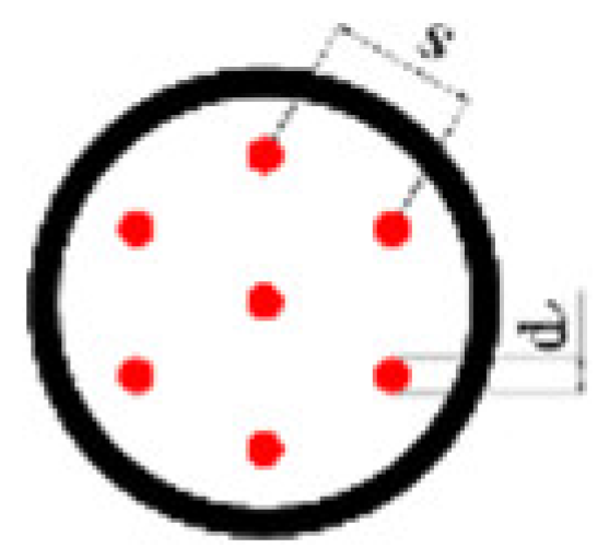 | 5.1 |
| 6 |  |  | 4.4 | |
 |  | |||
| 5 |  |  | 3.7 | |
| 4 |  |  | 2.9 | |
| Staggered | 7 |  |  | 5.1 |
| 6 |  |  | 4.4 | |
| 5 |  |  | 3.7 | |
| Product | Substance | Chemical Formula | Fraction | |
|---|---|---|---|---|
| LTP56 Polwax S.A. [31] | Paraffin | C19H38 to C32H65 | 100% | |
| RT54HC Rubitherm Technologies [32] | Fatty acid | C14H28O2 | 97% | |
| P1808 Konimpex Chemicals [33] | Fatty acid | C16H32O2 Palmitic acid | 58% | 96% |
| C17H35O2 Stearic acid | 38% | |||
| Parameter | LTP56 | RT54HC | P1808 |
|---|---|---|---|
| [°C] | 33.9–63.2 | 46.7–66.1 | 48.3–65.9 |
| [°C] | 40.1–54.9 | 37.9–52.8 | 38.1–53.5 |
| [J/(gK)] | 2.19 | 2.46 | 1.96 |
| [J/(gK)] | 2.21 | 2.59 | 2.25 |
| [J/g] | 159.4 | 220.6 | 178.5 |
Publisher’s Note: MDPI stays neutral with regard to jurisdictional claims in published maps and institutional affiliations. |
© 2022 by the authors. Licensee MDPI, Basel, Switzerland. This article is an open access article distributed under the terms and conditions of the Creative Commons Attribution (CC BY) license (https://creativecommons.org/licenses/by/4.0/).
Share and Cite
Fabrykiewicz, M.; Cieśliński, J.T. Effect of Tube Bundle Arrangement on the Performance of PCM Heat Storage Units. Energies 2022, 15, 9343. https://doi.org/10.3390/en15249343
Fabrykiewicz M, Cieśliński JT. Effect of Tube Bundle Arrangement on the Performance of PCM Heat Storage Units. Energies. 2022; 15(24):9343. https://doi.org/10.3390/en15249343
Chicago/Turabian StyleFabrykiewicz, Maciej, and Janusz T. Cieśliński. 2022. "Effect of Tube Bundle Arrangement on the Performance of PCM Heat Storage Units" Energies 15, no. 24: 9343. https://doi.org/10.3390/en15249343