Review

Research Progress and Prospect of Carbon Dioxide Utilization and Storage Based on Unconventional Oil and Gas Development

College of Petroleum Engineering, China University of Petroleum, Qingdao 266580, China
*
Author to whom correspondence should be addressed.
Energies 2022, 15(24), 9383; https://doi.org/10.3390/en15249383
Submission received: 14 November 2022 / Revised: 28 November 2022 / Accepted: 5 December 2022 / Published: 11 December 2022

Abstract

:
Energy security and the reduction of greenhouse gases such as carbon dioxide are two major crises facing the world today. Using carbon dioxide to develop unconventional oil and gas resources is a positive way to reduce greenhouse gas emissions, which can significantly alleviate global energy security issues. This study systematically introduces the prerequisites for CO2 to extract crude oil and CO2 to be safely and effectively stored. Under high temperature and high pressure, the rock properties of deep reservoirs are completely different from those of atmospheric conditions in the two-phase porous media environment of crude oil and high salinity formation water. The research progress on the phase behavior, mutual solubility, CO2 storage potential and mechanism between supercritical CO2 and crude oil, formation water and reservoir are reviewed in detail. In addition, CO2 leakage will inevitably occur during long-term geological storage, the proper estimation and evaluation of the risk and establishment of corresponding sealing methods are the way forward for CO2 geological storage. By systematically elaborating the nature, advantages and disadvantages of fluid–fluid, fluid–solid interaction and geological integrity destruction mechanism, the directions in which several key problems should be solved were pointed out.

1. Introduction to CO2-EOR-CCUS Technology in Unconventional Reservoirs

The continuous global CO2 emission leads to an upward trend of atmospheric CO2 concentration, leading to continuous climate deterioration and warming and frequent local disasters [1,2]. One of the biggest threats facing mankind in the 21st century is the greenhouse effect, which has become an international political struggle and a very sensitive topic in the international community [3,4,5,6]. In order to stabilize CO2 levels in the air at a reasonable level, effective ways must be found to reduce the amount of CO2 released into the atmosphere during the production and consumption of fossil fuels. Transferring CO2 to geological reservoir structures that use or store CO2 is a good option. Existing research and application results at home and abroad show that oil and gas reservoirs are well-sealed underground gas reservoirs, which can realize long-term storage of CO2. At the same time [7,8,9,10], if properly applied, injecting CO2 into the reservoir as a displacement agent can significantly improve oil and gas recovery, thereby achieving a win–win situation of CO2 reduction and utilization.
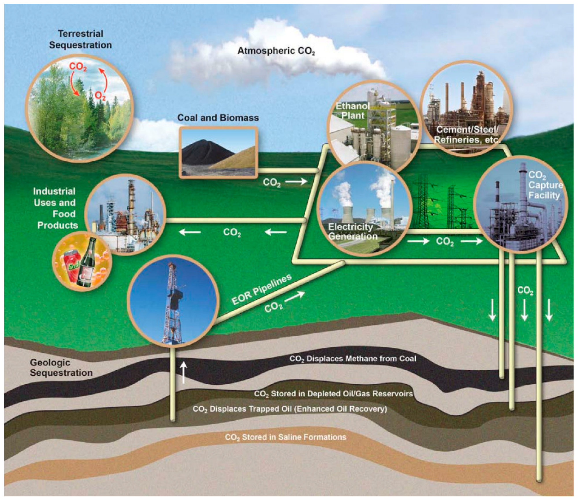
The United States, the former Soviet Union, Canada, the United Kingdom and Hungary have carried out a large number of CO2-flooding laboratory and field tests. Many successful projects have been carried out in Colorado, Louisiana, Mississippi, Oklahoma and other areas [11,12,13,14,15,16,17,18,19,20], as shown in Table 1. Since the mid-to-late 20th century, steam flooding has been the number one, enhanced oil recovery technology in the United States, and CO2 flooding is number two. As can be seen from Figure 1, after CO2 is injected into the reservoir, it continuously contacts and dissolves in the crude oil and formation water, forming the buried dissolved gas, which makes the volume of the crude oil expand, the viscosity decrease, the fluidity increase, and easier to be recovered [21,22,23,24]. In addition, under the influence of CO2 properties, CO2 is easy to miscible with crude oil; the additional resistance is reduced, the interfacial tension is reduced, and the oil displacement efficiency is improved [25,26,27,28,29,30,31]. Therefore, how to achieve the maximum miscible zone with crude oil in the formation state by using CO2 flooding is the main research topic of petroleum scientists.
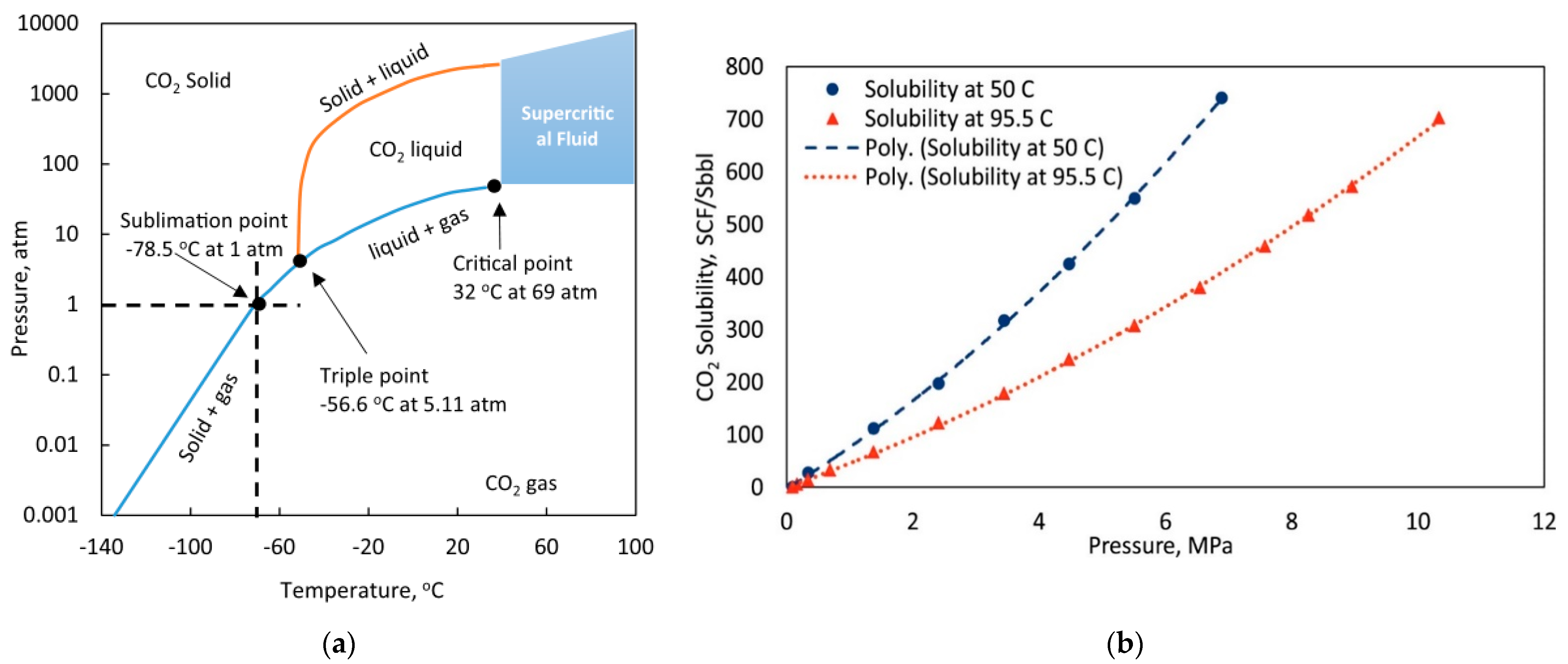
In many oilfields, water injection EOR technology has been mature, but water injection has entered the late stage, and there is still a large amount of remaining oil that cannot be recovered. New oil recovery methods and gas injection enhanced oil recovery technology have great potential for enhancing oil recovery. The reserves suitable for gas injection are very large in China. For oilfields with difficult water injection (such as unconventional reservoirs with low permeability and strong water sensitivity), CO2 injection is a feasible development method. The displacement and sequestration mechanisms involved in EOR-CCUS for CO2 injection in unconventional reservoirs have been reviewed by multiple teams based on their physical properties, availability, and cost [32]. Carbon dioxide storage sites are often referred to as deep geological formations, and it is a common practice in the oil and gas industry to inject carbon dioxide into reservoirs at specific depths (over 800 m) to enhance oil production, also known as enhanced oil recovery (EOR) [33,34,35]. For example, at ambient temperature, carbon dioxide behaves as a gas, but at a temperature of 32 °C and a pressure of 7 MPa, it becomes a supercritical fluid (IPCC 2005; Oldenburg 2007), which typically occurs at depths greater than 800 m. In response to the needs of domestic unconventional oil reservoirs to improve crude oil production and recovery, the concept of integrating CO2 capture, CO2 flooding for enhanced oil recovery and underground storage was proposed, and the CCUS-EOR technology system was initially established. The whole process of CO2 capture, transportation, injection, produced-fluid treatment and produced-gas circulation injection has been fully practiced, and an injection mode suitable for pilot tests, expanded tests, and industrial applications have been developed [36,37,38], as shown in Figure 2.
There are four main storage mechanisms of CO2 in oil reservoirs: (1) Structural formation storage mechanism: Under the influence of geological structure, when CO2 is injected into the oil reservoir, CO2 continues to migrate when it encounters caprocks and barrier layers. Afterwards, CO2 is blocked and cannot continue to migrate and is left in the structure to achieve underground storage. Structural formation sequestration mechanisms generally come into play after CO2 begins to be injected into the formation. (2) Mechanism of binding or capillary storage: During the migration of CO2 in the formation, a part of CO2 is retained in the pores of rock particles for a long time due to the influence of capillary force and relative permeability. Often, a tethered or capillary storage mechanism is combined with a dissolution storage mechanism and will eventually dissolve in the formation fluids. (3) Dissolution and sequestration mechanism: There is always crude oil and formation water in the oil reservoir. When CO2 is injected into the oil reservoir, CO2 is in continuous contact with the crude oil and formation water in the oil reservoir and dissolves in it to achieve sequestration. The main factors affecting the dissolution and storage of CO2 are the saturation of CO2 in formation water and crude oil, the chemical composition of formation water, and the composition and contact rate of crude oil. (4) Mineralization physico-existing mechanism: CO2 reacts with water/salt to form carbonic acid and reacts with rock minerals to form secondary carbonate ions and produce precipitation, which is the mineralization physico-existing mechanism. The mineralization physico-existing mechanism is mainly affected by the mineral composition, fluid type and chemical reaction process of the formation rock. Usually, the action scale of mineralized sequestration is quite long. The mechanism and main controlling factors of CO2 sequestration in oil reservoirs are seen in Table 2.
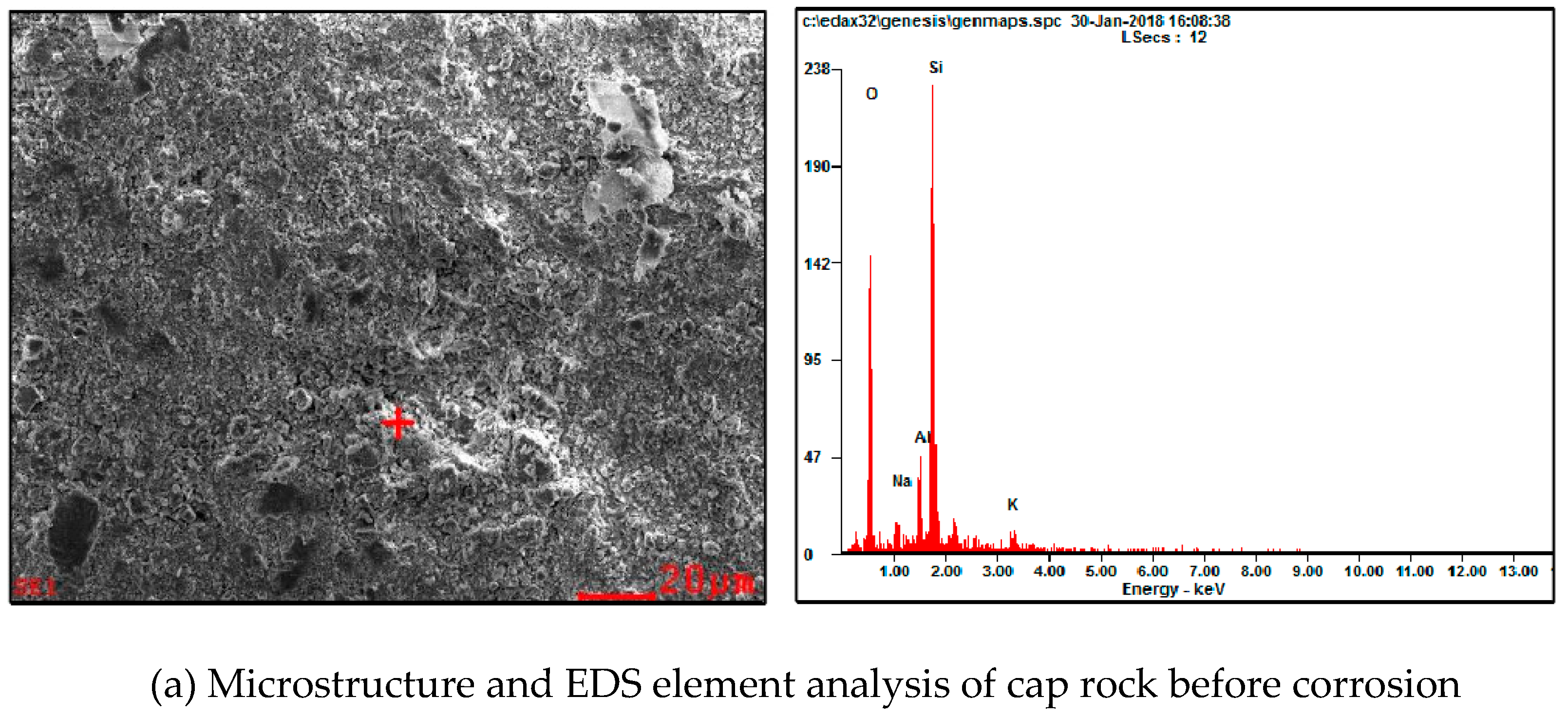
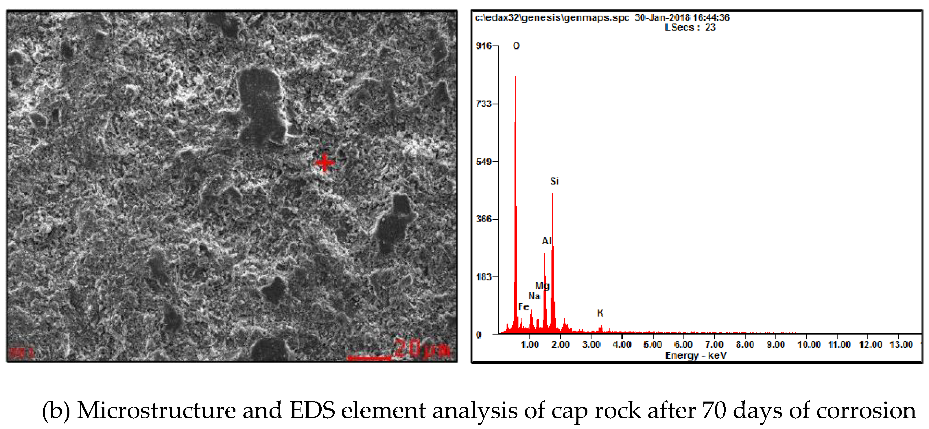
After CO2 is injected into the formation, the CO2 in the reservoir mainly exists in the porous medium in the form of microscopic residual gas [39,40,41]. It can be dissolved in oil and water to lower the pH of formation fluids or captured by the primary minerals in the reservoir and undergo a series of chemical reactions to generate secondary minerals. At this time, the surface minerals of the sedimentary rock reservoir under acidic conditions will be subject to chemical dissolution. This phenomenon will cause changes in the porosity and permeability of the reservoir by changing the mineral composition and pore structure of the rock, which will further lead to the rock skeleton. The particles soften, causing their strength properties to be greatly reduced, resulting in serious geological disasters [42,43,44,45,46,47,48,49,50,51,52,53,54,55,56]. In Figure 3, SEM and EDS elemental analysis techniques were used to compare the changes of cap rock micromorphology before and after corrosion [57]. Therefore, the dissolution effect of the acidic fluid formed by CO2 dissolved in water on the reservoir rock is a non-negligible issue in judging whether CO2 can be safely stored.
Therefore, the scientific significance of this review is mainly to provide basic data for CO2 flooding and storage potential evaluation and strategic planning in unconventional reservoirs and to provide a basis for CO2 large-scale storage and resource utilization. In a porous medium environment with two phases of crude oil and high salinity formation water at high temperature and pressure, the rock properties in deep reservoirs are completely different from atmospheric conditions. The phase state, mutual solubility, thermodynamics and geochemistry between supercritical CO2 and crude oil, formation water and reservoir are comprehensively reviewed. This determines the final storage amount and occurrence state of CO2 and reveals the main mechanism and storage potential of CO2 storage in the reservoir. Emphasis is placed on the interaction between fluid and rock in the reservoir under CO2 storage conditions. Through the investigation of a large number of laboratory experiments, theoretical analysis and numerical simulation methods, the mechanism of the failure of the geological integrity of CO2 storage is clarified, so as to guide CO2 flooding and oil displacement. The geological selection of the storage area and the determination of production parameters reduce the risk of CO2 leakage in the storage area. A comprehensive overview of EOR-related research focusing on high-pressure gas injection in unconventional reservoirs has been presented [58,59]. Although this review is not the first literature review of CO2-EOR-CCUS in unconventional formations, it is intended to be fairly comprehensive and will discuss gaps in the literature and the way forward. A number of recommendations for enhanced oil recovery in future EOR trials based on field trials [60,61], laboratory tests, and insights gleaned from modelling and simulation studies will be outlined for initial site selection and post-storage safety for future CCS projects and will provide scientific theoretical basis and technical support.

2. Study on the Influence of CO2 Storage on Formation Fluid

Research shows that for unconventional reservoirs, the average production coefficient after primary and secondary oil recovery is usually less than 20% (Han and Bian, 2018) [62]. CO2 as an oil displacement agent is the most effective and economical method to enhance oil recovery and geological storage of CO2. When CO2 comes into contact with brine or crude oil, CO2 is gradually diffused and dissolved in brine/crude oil, and CO2 is buried in unconventional reservoirs. The main mechanism is displacement, dissolution and retention, physical trap, etc. [63]. At the end of CO2 displacement, the CO2 dissolved in the water phase and oil phase of the reservoir is nearly saturated, and this part of CO2 can be considered as the dissolved buried stock of CO2 in the formation fluid. During the dissolution process, the change of pressure, temperature and CO2 concentration in brine/crude oil will have an important impact on the dissolution rate of CO2. By mastering the diffusion law of CO2, long-term safe and effective CO2 geological burial can be carried out. Equation of state and diffusion equation of CO2:
Δ n t = n 0 n t = 1 R T ( p 0 V 0 Z 0 p t V t Z t ) = ( p 0 p t ) V Z ¯ R T = Δ p t V Z ¯ R T
D t = 1 4 ( p 0 p t p 0 p ) 2 π h 2 t
c t = Δ n t L = Δ p t V Z ¯ R T L
where (1) Δnt is the number of moles of CO2 dissolved in the solution of the contacted system at time t calculated by the gas equation of state, mol; and ct in formula (3) is the solubility of CO2 in the contacted system at time t, mol/L. In formula (2), Dt is the variable diffusion coefficient of CO2 in the liquid phase diffusion process obtained by the pressure depletion method, m2/s.

2.1. Dissolution, Diffusion and Storage of CO2 in Crude Oil

When CO2 interacts with crude oil, crude oil will not only affect the dissolution and diffusion of CO2, but also affect the high-pressure physical properties, saturation pressure, viscosity and volume coefficient of crude oil. The expansion of crude oil under the action of CO2, the reduction of crude oil viscosity and the reduction of CO2 crude oil interfacial tension are important oil recovery mechanisms. In the process of enhanced oil recovery by CO2 flooding, the diffusion law of CO2 and the change of physical properties of crude oil will directly affect the final oil displacement effect.
In the initial stage of development, unconventional reservoirs usually form a large number of artificial fractures through hydraulic fracturing, forming a complex fracture network. Hawthorne et al. (2013) [64] carried out research on CO2 oil displacement mechanism of tight reservoirs. They believe that the mechanism of CO2 displacement in unconventional reservoirs such as tight reservoirs is different from that in conventional reservoirs. The flow of CO2 is in fractures, not in the rock matrix. In addition, they theoretically explained the flow process of CO2 injection into tight reservoirs through four steps (as shown in Figure 4): (1) at the initial stage of CO2 injection, CO2 quickly flows through fractures. (2) CO2 seeps into the rock matrix under pressure gradient. CO2 expands and pushes crude oil out of the rock matrix. (3) With the continuous penetration of CO2 into the matrix, the amount of CO2 diffused and dissolved into the crude oil increases, the viscosity of the crude oil in the matrix decreases, and the crude oil is mixed into the CO2 bulk phase in the fracture under the action of expansion and viscosity reduction. (4) The CO2 pressure gradient inside and outside the rock matrix gradually decreases, while the hydrocarbon components in the oil-CO2 mixed phase in the matrix diffuse into the fracture due to the hydrocarbon concentration difference between the matrix and fracture system. Finally, the oil-CO2 mixed phase in the fracture begins to flow to the production well. In the process of displacement, CO2 crude oil dissolution and diffusion reach equilibrium. At the end of production, the amount of CO2 in the crude oil that has not been recovered is the crude oil dissolution buried amount of CO2. Research on the dynamics of CO2 in the reservoir and its effect on formation fluids is necessary for CCUS. Zhao, C. L. (2019) [65] proposes a method to study CO2 cold flooding reservoirs through relevant parameters such as fluid temperature and pressure. The simulation results show that the oil recovery factor and the gas–oil ratio are positively correlated with the injected fluid temperature. Meanwhile, Hye Seung Lee (2021) [66] studied the effect of impurity-containing CO2 on EOR and CCS performance, and the results showed that impurities in CO2 reduced oil recovery by 9.2% and total CCS performance by 4.3%.
Both laboratory experiments and numerical simulation verify that enhanced CO2 injection in unconventional reservoirs can greatly enhance oil recovery and have great CO2 storage capacity, as shown in Table 3. The solubility of CO2 in oil is significantly affected by temperature and pressure, as shown in Figure 5 [29]. However, Alfarge et al. (2018) [67] compared the tertiary oil recovery growth rate of the above two research methods with that of the pilot area and concluded that the crude oil recovery rate of the pilot area was far lower than the results of laboratory experiments and numerical simulation. They also announced that molecular diffusion has played a role in improving CO2 injection recovery in tight reservoirs, but due to the low diffusion coefficient of CO2 molecules in the field, the diffusion mechanism has a delay effect in the field.

2.2. Dissolution, Diffusion and Storage of CO2 and Brine

Nowadays, brine formation is the main place for the geological storage of CO2. Most of unconventional oil reservoirs are initially developed through hydraulic fracturing, and the CO2-WAG method is used for reservoir development during the production process. The storage mechanism of CO2 and brine is also crucial. The main mechanism is dissolution retention, mineralization reaction, physical trap, etc. Hydrodynamic diffusion and dissolution coefficient are the main controlling factors. When CO2 diffuses in brine, the effective range of dissolution is affected by the salinity of the water, and the amount of dissolved sequestration decreases with the increase of the salinity of the brine.
Philip S. Ringrose (2018) [73] mentioned that the Norwegian CCS has stored 22 metric tons of CO2 in the offshore brine aquifer since 1996, and the overall storage efficiency reached about 5% of the pore volume, of which the volume of CO2 dissolved in the brine phase accounts for about one-tenth of the volume. Wei Liu (2021) [74] studied the diffusion of CO2 in the oil–water liquid phase system through microscopic experiments and simulations, as shown in Figure 6. The study showed that temperature and pressure are the key influencing factors. With the increase of pressure and temperature, the CO2 diffusion coefficient increases correspondingly. Danchen Li (2021) [75] studied the efficiency of simultaneous CO2 release and storage in ultralow permeability (<1 mD) core samples from the Yanchang Formation in the Ordos Basin, China with different injection strategies of continuous gas flooding, alternating water injection and cyclic gas injection. They claim that WAG achieves high CO2 storage goals while achieving high recovery. Mohamed Khather (2019) [76] believes that during CO2-EOR in carbonate reservoirs, the formation water is carbonated by CO2, dissolving the main constituent minerals of carbonate reservoirs, as shown in Figure 7. Dongfeng Zhao (2021) [77] believed that pore-throat structure and permeability changes caused by precipitation and rock matrix dissolution are serious problems for enhanced oil recovery. The experimental results show that pressure has a great influence on the production of precipitation, and there is no precipitation near gas injection wells with high pressure, while a large amount of carbonate deposits is produced near low-pressure production wells. Reservoir pressure, temperature, and brine concentration all directly affect the CO2 dissolution process in brine. Valle L M (2020) [78] believes that the heterogeneity of the formation will affect the liquid phase migration and its ability to store CO2, through experiments. It proved that due to the dissolution-precipitation phenomenon of carbonate, CO2 dissolution contributes to the increase of injection capacity and is conducive to storage sealing and storage capacity. The higher the salt concentration of brine, the lower the dissolved CO2 and the slower the diffusion rate, but the influence of pressure and temperature is greater than that of salt concentration.
In CO2 geological storage, experimental research and numerical simulation results have proved that brine I s an important site for CO2 storage with the advantages of large storage volume, long storage time and wide distribution of storage sites, as shown in Table 4.
The effects of CO2 sequestered in the formation fluid can be reflected by the interaction between CO2 and the formation fluid, and the degree of influence can be shown in oil recovery, the solubility of CO2 and the diffusion coefficient [84,85,86]. Comprehensive indoor experiments and numerical simulations were used to demonstrate the effectiveness of CO2 storage in formation fluids [87,88,89]. However, it is important to consider whether the heterogeneity of the complex matrix fracture of the actual reservoir has an effect on the amount of storage during various studies.

3. The Effect on Reservoir Property with the Reaction between CO2 and Rock for Unconventional Reservoir

For CO2 sequestration or CO2 flooding in CCS or EOR, there is a common phenomenon that CO2 may occur in a chemical reaction with the formation rock in different degrees based on many factors, such as temperature and pressure of the formation, type of rock, etc. Due to their weak acidity, several minerals can react with carbon dioxide injected into the reservoir. The two most common rocks that can interact with carbon dioxide in shale reservoirs are limestone and dolomite [90]. With higher injection pressure, more rock will be dissolved, and with the decline of pressure, dissolved carbonate was observed to be precipitated along the flow path [91]. Master et al. [92] confirm that rapid acid neutralization rates and water–rock reactions can sufficiently construct safe and permanent storage of CO2. It may be possible for granite and/or sandstone to capture CO2 at hydrothermal conditions [93]. As a result, channels, pores and fractures may be created based on rock reactions. Furthermore, the reaction can also produce precipitates such as calcium oxide or magnesium oxide with limestone and dolomite, respectively. Those mentioned above affect reservoir property, such as porosity and permeability, which is of importance for the guide of CO2 injection in CCS or EOR. We will introduce previous studies of CO2-rock reactions based on different methods.
For experimental methods, there may include hydrothermal autoclave experiments, with some auxiliary methods to explore rock properties, such as X-ray diffraction (XRD) and scanning electron microscopy (SEM).
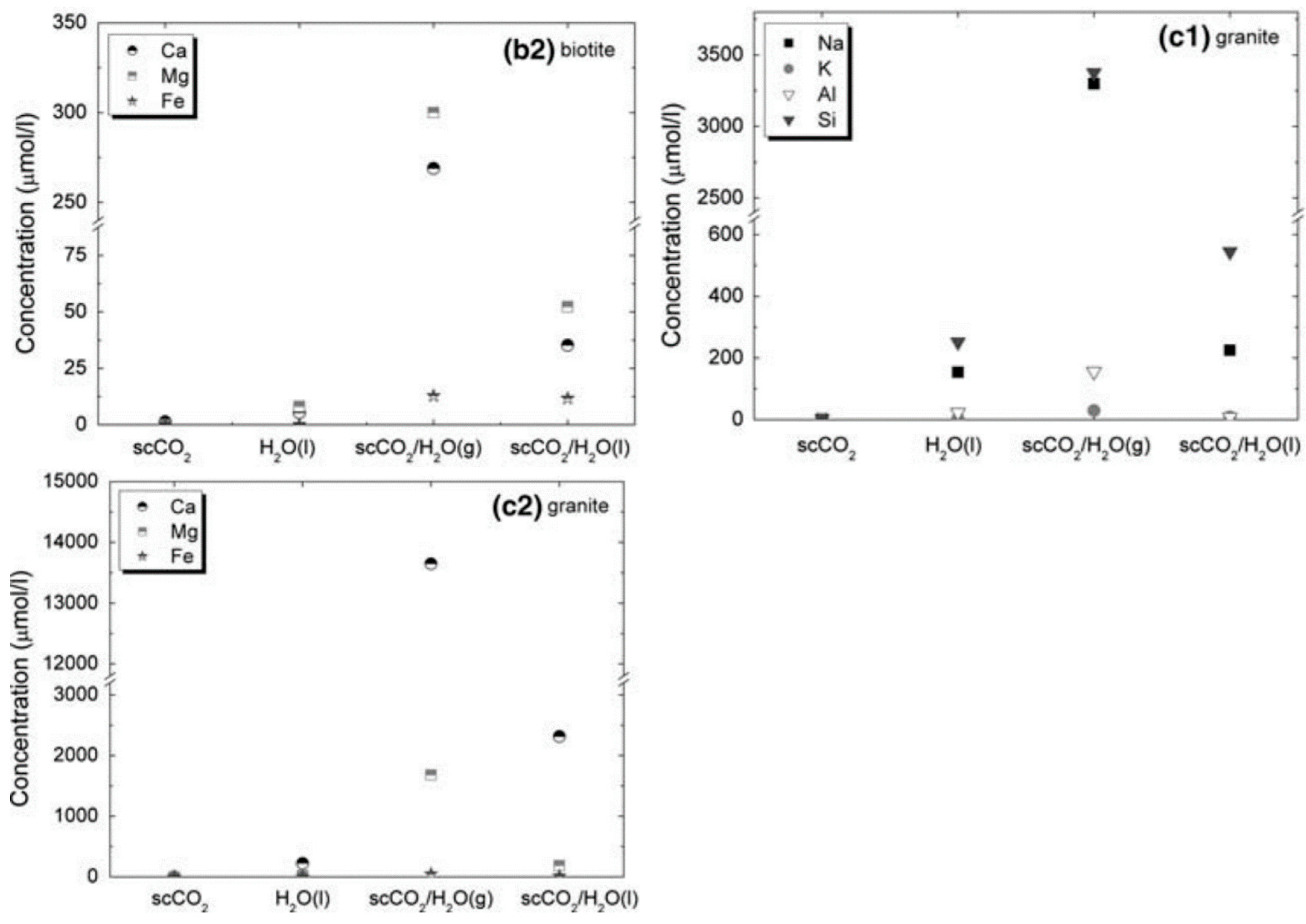
For static research, Lin et al. [94] carried out an experiment to discover basic interactions in the scCO2/water/rock minerals (quartz, biotite and granite) at 100 ℃. They found that the water-granite system increases the dissolution rate of CO2 and no reactions occur in the above system without water under a steady state, shown as Figure 8. Under hydrothermal temperature conditions, calcium released from rocks (silicates) easily and transferred into CaCO3 and/or CaSO4 during CO2 sequestration back to nature [95]. Dissolution of the carbonate minerals has the most significant change in the reacted samples immersed in the CO2-saturated brine, especially calcite, which shows severe dissolution. Only in the scCO2 system, was a slight change observed [96]. Zhao et al. [97] observed that the carbonate minerals were corroded dramatically, followed by feldspar, and quartz least. Corrosion, secondary minerals and precipitate increased the sorted behavior of rock throats and decreased the permeability. Primary dissolution of calcite and chlorite minerals may be re-precipitated as secondary ones, such as more stable dolomite and ankerite cements [98]. Using microscopic methods, Pearce et al. [99] found that Kaolin and fine-grain movement have the potential to open or jam pores, potentially increasing or decreasing permeability and CO2 injectivity. The reaction between CO2 and rock may affect capillary pressure due to pore structure change [100]. Fracture, also an important role for CCS or EOR, based on a series of static soaking experiments. Calcite, dolomite, K-feldspar, and albite were diversely dissolved after the soaking of CO2-saturated brine, and this leads to an increase of porosity and permeability and decrease of tensile strength and surface friction coefficient, and may induce the growth with a fracture [101].
For simulation methods, there may include molecular dynamics (MD), lattice Boltzmann method (LBM), pore-throat networks, etc. Each of them has different aspects to evaluate the effect of the CO2 reaction process on the rock. Usually, two dimensionless numbers with Péclet (Pe) and Damköhler (Da) number are introduced to represent the strength between advection and diffusion and the relative size between reaction rate and diffusion.
As Figure 9 shows [102], there are many applications for MD to research CO2 sequestration. Many studies focus on the wettability of the surface to explore the interaction between CO2 and rock. Compared with different rock types in the CO2-water system, sandstone and limestone, plus pure minerals such as quartz, calcite, feldspar, and mica, are strongly water wet, and oil-wet limestone, oil-wet quartz or coal is intermediate wet or CO2 wet [103]. Chen et al. [104] combined MD and surface chemical experiments to study the wettability alteration of rock caused by contamination and/or CO2 reaction. The capillary capture amount of CO2 is mainly determined by the capillary pressure of water and CO2 in the reservoir, which is reflected by the interfacial tension (IFT) and contact angle (CA) of the CO2/water/rock system. MD can consider the reaction between carbon dioxide and water. The more CO2 dissolved, the more improvement of IFT that can be achieved with rock surface [105]. McCaughan et al. [106] carried out a molecular dynamics study of the effect of divalent salts on the contact angle of CO2/water/quartz and investigated N2/water/quartz and H2S/water/quartz systems to evaluate the effect of gas on the contact angle. The quartz surfaces used for these simulations are fully coordinated quartz crystals. It is very common that clay may be swelled under an aqueous system. Myshakin et al. [107] considered that the degree of swelling caused by an insert of CO2 strongly depends on the initial water amount in the interlayer space, and CO2 intercalation promotes inner-sphere adsorption of the positively charged interlayer ions on the clay surfaces, which improves the wetting properties of the surfaces.
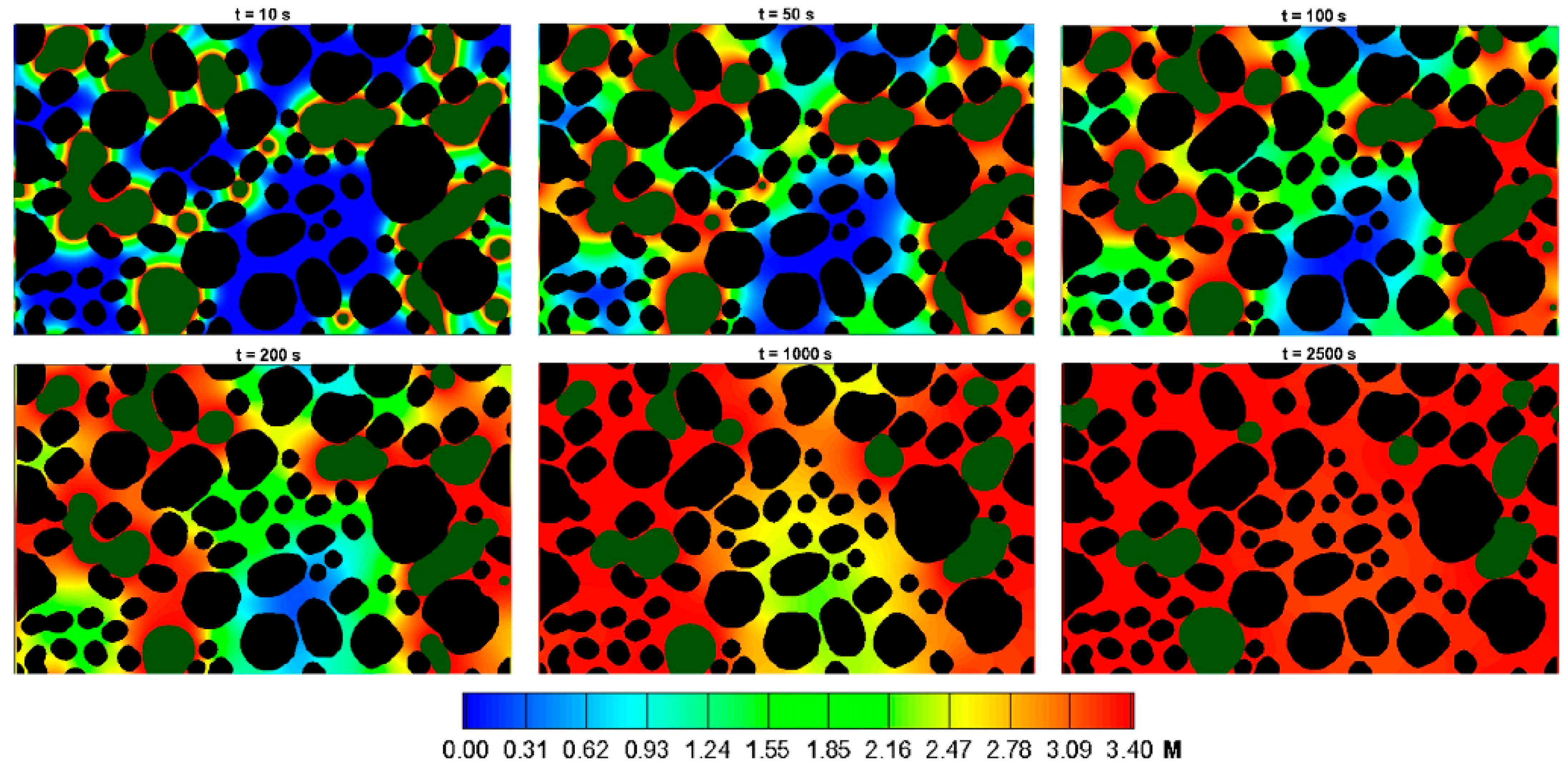
Recently, many LB models are structured with advection and diffusion under heterogeneous reactions to explore the interaction between CO2 and rock. With a two phase system, relative permeability is influenced by chemical reactions indicated by digital figures. Tian et al. [108] gave the relationship between porosity and fluid speed with time step based on the advection-diffusion process. An et al. [109] developed a pore-scale simulation to model reactive transport in carbonate rocks; they found that dissolution occurs more homogeneously with an increase in flow rate. Except for porosity and permeability, grain size and reaction rates on the fluid-solid system can be obtained with high accuracy in 2D [110]. Some studies develop the dimension of simulation to model more factual situations. Combining micro-CT and 3D LB with a CO2-water-rock system, porosity at the pore scale and permeability at the macro scale is recovered [111]. The effect of heterogeneous reactions, such as connections of pore channels and properties of the matrix, can be easily captured by LB in 3D mass transport system [112]. Fracture is also considered in 3D model. Compared with a lower injection rate of CO2-rich brine, the higher one makes fractured media more permeable [113]. With the more complex system, the multiphase-multicomponent model is constructed to explore the non-equilibrium process with CO2 dissolution in water shown in Figure 10 [114].
Constructing two-dimensional (2D) and three-dimensional (3D) pore-throat networks, small Pe and Da numbers, the concentration and dissolution patterns are more uniform [115] with the equation of state (EoS) compositional simulator for the simulation of CO2 storage in saline aquifers. The simulator (GEM-GHG) models the following phenomena: convective and dispersive flow in porous media; phase equilibrium between the oil, gas and aqueous phase; chemical equilibrium for reactions between the aqueous components and mineral dissolution and precipitation kinetics [116]. The safety of the capture process was assessed by considering leakage of mobile carbon dioxide through the caprock. For long-term CO2 storage, it was found that the conversion of CO2 to minerals depends on pre-existing minerals in the aquifer that provide the necessary ions for the reaction to occur [117]. Liu et al. [118] using CMG found that the high CO2 adsorption capacity of shale facilitates the injection of CO2 into shale reservoirs; the amount of CO2 adsorbed is proportional to the CO2 adsorption isotherm, while CO2 in other phases (gas/supercritical, dissolved, and mineral phases) is similar to CO2 adsorption isotherms in inversel proportion. Compared with different injection methods, regardless of whether the reservoir is heterogeneous or homogeneous, the water-gas alternation (WAG) scheme should be the first choice, as it can improve oil recovery and CO2 storage efficiency during EOR. Injecting CO2 after the CO2 EOR process can increase the CO2 storage capacity while keeping the reservoir pressure stable [80]. Graupner et al. [119] coupled software, ECLIPSE-OpenGeoSys, is presented and allows a combined simulation of multiphase flow, transport and geochemical reactions for storage of CO2 in deep saline aquifers, evidencing the achievement of coupled software. The amount of dissolved and precipitated minerals resulting from CO2-brine-rock interactions is site-specific and depends primarily on the initial aquifer mineralogy and brine composition [120]. We list mentioned studies above for conclusion in Table 5.

4. Study on Leakage and Gas Detection Mechanism and Chemical Control Method in CO2 Flooding Process

4.1. Numerical Simulation and Uncertainty Quantitative Analysis of CO2 Storage Problems

The carbon dioxide storage problem can be described by coupling multiple physical fields with the multiphase flow in porous media. Physics-based reservoir numerical simulation technology has been widely used [121]. The key to CO2 sequestration simulation is accuracy, otherwise CO2 leakage may bring a series of environmental problems and safety issues [122].
To improve accuracy, we will consider a large number of physical and chemical reactions in the simulation, such as the stress field, the reaction of carbon dioxide and minerals, etc. For example, Bao et al. [123] considered the effects of pressure accumulation, surface displacement and induced earthquake risk during CO2 injection. The model simulates the change of the stress field, the migration of injected CO2 and the geomechanical behavior of the surrounding geological strata, Yin et al. [124]. In order to greatly reduce the computational cost, a coupled inversion framework based on a wave modeling operator, rock property transformation and proxy fluid flow simulator is introduced, which can accurately use the Fourier neural operator as the proxy of the fluid flow simulator. Similarly, Wei et al. [125] coupled hydrodynamics in the safety simulation study of carbon dioxide geological sequestration, considering the mechanical stability of the reservoir overburden during carbon dioxide injection. Bao et al. [126] proposed a thermal-hydro-mechanical coupling model for stress, deformation and shear-slip failure analysis, based on an open-source finite element solver Elmer, designed to reliably and accurately simulate the entire CO2 injection cycle.
Now consider the chemical reaction of CO2-EOR simulation packages of which there are only a few, such as WinProp-CMG-GEM (computer Modeling Group LTD.) and STOMP-EOR. Dai et al. [127]. Weonshikhan et al. [128] consider the fundamental constraints of CO2 injection into the mobile CO2 phase beneath the subsurface low-permeability cap, CO2 conversion to mineral deposits, dissolution in in-situ fluids, and surface tension (capillary forces). The competitive effects of these different capture mechanisms are evaluated and quantified, including the relative storage of each mechanism. Babak Shabani et al. [129] introduced a new TOUGHREACT module, CO2Bio, to simulate geological carbon storage (GCS) under biological conditions, which is capable of predicting the mutual solubility of CO2-CH4-H2S-H2 gas mixtures and brine. Density, viscosity and enthalpy of the CO2-CH4-H2S-H2 gas mixture were calculated. Dynamic production and/or consumption of CO2, CH4, H2S and H2 gases can be predicted, as well as multiphase flows of CO2-CH4-H2S-H2 gas mixtures and brine under deep geological conditions.
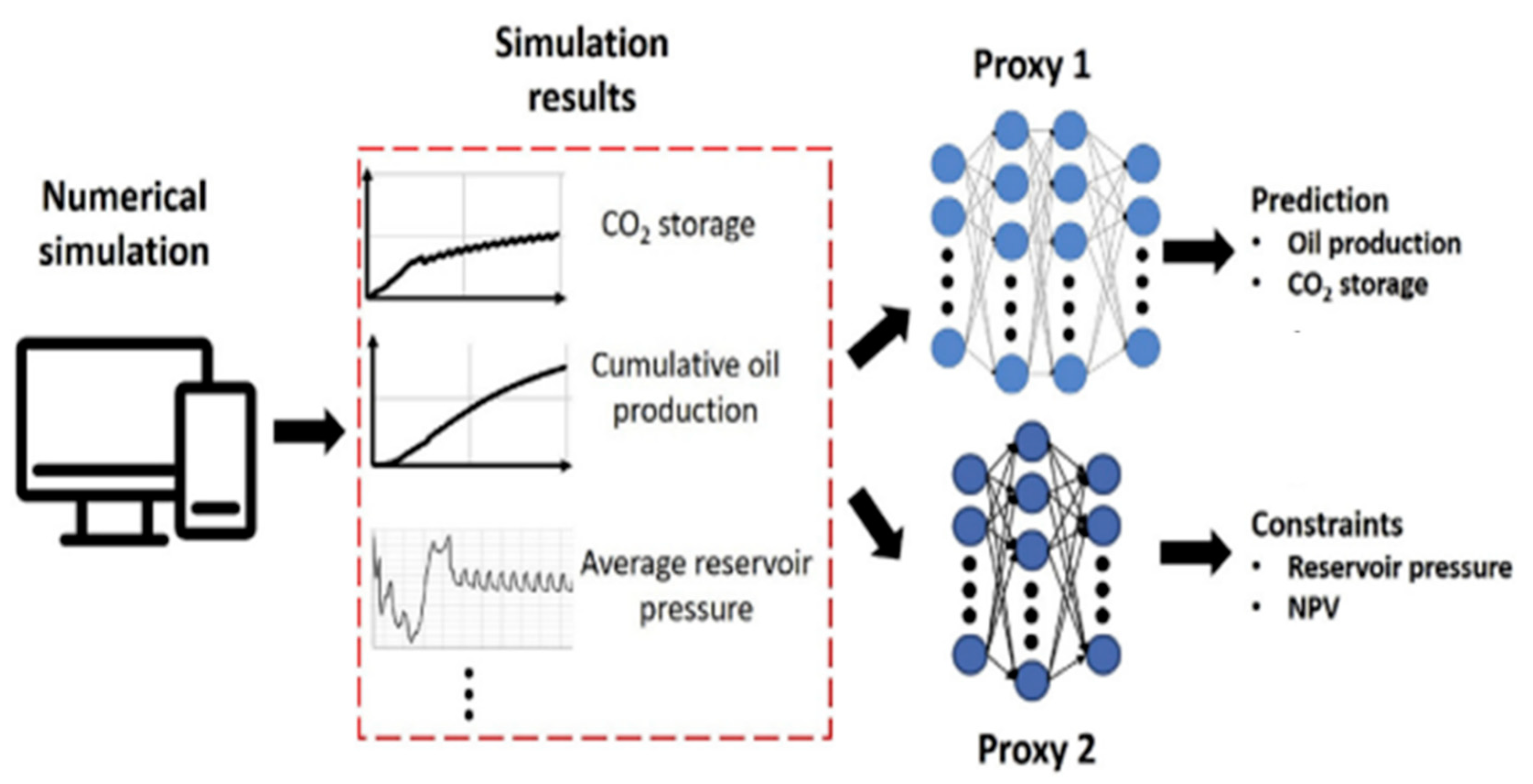
Even though we can consider the coupling of multiple physical and chemical fields in the model, the uncertainty of the model results comes from many factors [130]. First, we consider the uncertainty of multiphase flow parameters. In particular, the relationship between relative permeability and capillary pressure depends on both rock properties and fluid properties, which can be highly nonlinear with changes in fluid temperature and pressure conditions. The selection of relative permeability and capillary pressure functions and how these functions are calibrated and constrained influence the prediction of trapping mechanisms, phase behavior, and plume motion [131]. Second, we consider the uncertainty of fractures. Bao et al. [132] system to evaluate fracture belt in the process of CO2 injection to uplift, the influence of formation pressure build-up and its research think permeability fractured zone 2~3 orders of magnitude smaller than the reservoir permeability, the fractured zone is an impermeable block, and its resistance to the reservoir fluid migration result in fracture belt near the pressure increased. Thirdly, we consider the effect of long-term CO2 storage on the reservoir. The decrease of porosity and permeability caused by precipitation and the increase of porosity and permeability caused by mineral corrosion should be considered. The issue is an open one, and no technology has been fully recognized as universal or proven to be a “perfect” enhancement technology [133]. The fourth consideration is volatile oil price. Although EOR and CO2 sequestration can be accurately predicted, the time horizon is so long that current oil prices are not very relevant. Carbon dioxide sequestration must take into account economic factors. Volatile oil prices are a major obstacle to CO2-EOR and storage projects. In Figure 11,The CO2 injection process must be optimized to obtain the best oil production, CO2 reserves and economic parameters, such as net present value [134].
How to speed up the computational efficiency while ensuring the accuracy of simulation becomes the key problem. At present, most of the research focuses on deep machine learning (such as artificial neural networks and establishment of the proxy model), model reduction and other methods. Yan et al. [134], for example, trained a two-stage deep learning model for the different main driving forces of fluid flow and migration in CO2 injection and post-injection stages in Figure 12. This deep learning workflow not only provides high-fidelity predictions at both time and space scales, but is 250 times faster than full physical reservoir simulations. Zheng et al. [135] developed simplified dimensional models (such as vertical equilibrium (VE) and dynamic reconstruction (DR) models) based on vertical integrals of full-dimensional governing equations. The simulation results show that the proposed model keeps the accuracy of the conventional full-dimension model while significantly reducing the computational cost. Chen et al. [136] introduced a generic component-based multi-physics analysis code-Albany—for modeling and analysis of GCS problems, which showed good accuracy and computational efficiency. You et al. [137] describe a machine learning-based workflow that uses the proposed neural network training method to train a proxy model capable of predicting the time series of cumulative oil production and carbon dioxide reserves. Its field application of the ongoing CO2-EOR project in the Farnsworth field in Texas, USA, proved to be fast, robust and stable. Biondi et al. [138] applications to explore potential CO2 (or hydrogen) geological storage sites by reprocessing existing seismic data sets and long-term monitoring of CO2 (or hydrogen) underground injection processes. Chen et al. [139] use machine learning algorithms: multivariate adaptive regression splines (Multivariate Adaptive Regression Splines), from saline aquifer CO2 injection, and subsequent multiphase fluid flow of the whole physics in the numerical simulation results export high computational efficiency.A reduced order model of this greatly improves computational efficiency. Mo et al. [140] proposed an adaptive Kriging method to establish a GCS model agent for rapid evaluation. The agent model was effectively generated by an adaptive experimental design algorithm based on Taylor expansion, combined with distance-based exploration criteria and utilization criteria, and adaptively searched for training samples with large information content.
Another way is to develop professional CO2 sequestration software. At present, most commercial software has also developed carbon dioxide storage modules, but its high use cost and the limitation of the model make the scientific research work complicated. White et al. [142] developed a new numerical simulation device for the scientific study of enhanced CO2 recovery and sequestration. Named STOMP-EOR, the simulator solves coupled conservation equations for formation energy, water saturation, CO2 concentration, CH4 concentration, salt concentration and petroleum component concentration in three-phase flow conditions. The market for specialized software is huge and difficult.
On the premise of ensuring the accuracy of the model and efficiency of calculation, we need to consider the influencing factors of oil displacement rate and storage rate when conducting the study of enhanced carbon dioxide recovery and carbon dioxide storage. The first is the type of reservoir. There are different factors to consider for different reservoirs. Shale formations, for example, need to prioritize carbon dioxide adsorption and methane displacement. [143] second, reservoir heterogeneity. The heterogeneity of the reservoir will affect the swept area of carbon dioxide and thus affect the storage effect. Yu et al. [144] revealed the effects of changes in horizontal permeability (Kh), Kv/Kh ratio and CO2 injection rate on CO2 saturation, plume distribution and CO2 dissolution in salt-bearing reservoirs through various sensitivity analyses. Third, injection parameters. Different injection rates and injection methods will have an impact on CO2 sequestration. Terranngoc et al. [145] considered the effects of different hydrodynamic parameters, chemical properties and geometric parameters on CO2 injection in brine reservoirs. The result is a 5-year intermittent injection cycle with a maximum injection rate of 20 kg/s and no injection for six months at lower fracturing pressures. This solution maximizes carbon dioxide stored in aquifers. Fourth, production parameters of production Wells. William et al. [146] selected uncertain variables such as bottom hole injection pressure, WAG cycle, injection group and production group rates, and gas-oil ratio. Select the most significant variable as the control variable. In the optimization process, vertical permeability anisotropy (Kv/Kh) was taken as one of the uncertain parameters. Fifth, the existence form of carbon dioxide. The presence of carbon dioxide also affects recovery and retention. Supercritical state, miscible state, etc. Cheng et al. [147] performed a sensitivity analysis of a deep confined saline aquifer model for supercritical CO2 injection using STOMP numerical procedures. Including inherent permeability, porosity, pore compressibility, capillary pressure-saturation/relative permeability parameters (residual liquid saturation, residual gas saturation change), the effects of each parameter on CO2 injection rate and cost were determined.

4.2. Leakage Paths and Risk Analysis of CO2 Geological Storage

Media commonly used for geological storage include: oil and gas reservoirs, deep saline aquifers, and coal beds [148,149]. To date, they have been successfully demonstrated at pilot and commercial scales in oil and gas reservoirs and deep saline aquifers [121]. Twenty years ago, one million metric tons of carbon dioxide were injected annually into the North Sea aquifer [44]. Canada and Algeria sequestrated over 20 million tons (Mt) of CO2 in their deep geological sites [150,151]. However, there have been a few issues raised in recent years, indicating the potential leakages paths created during CO2 geological storage. One of the challenges in regard to CO2 storage is the proper estimation and evaluation of leakage channels and risks in these media.
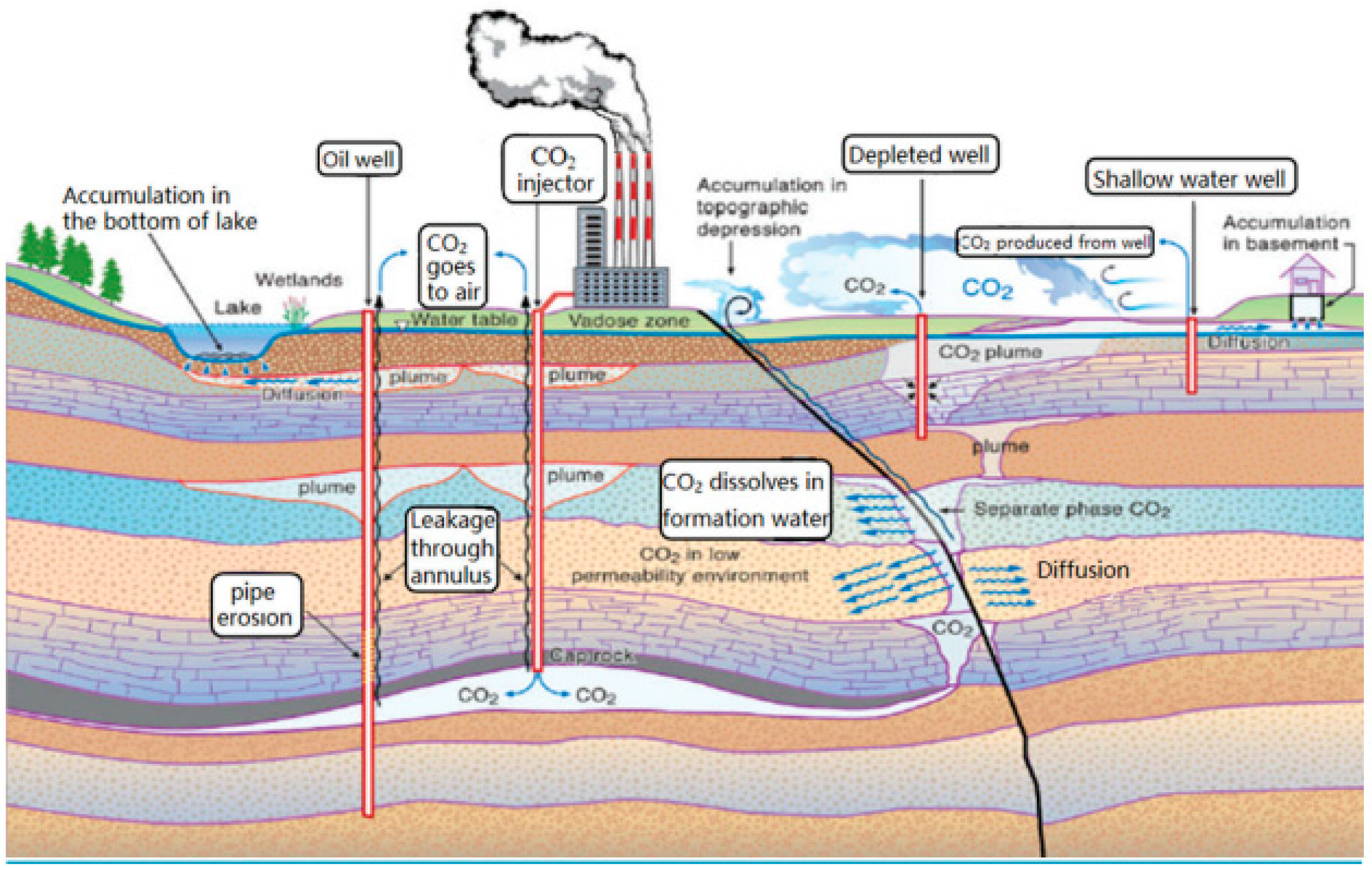
Leakage of CO2 geological storage depends on a multitude of factors which can be grouped into several categories: (1) Incomplete or improper disposal of abandoned wells will lead to the risk of CO2 leakage [152,153,154], depicted in Figure 13. (2) Under the action of buoyancy, CO2 will constantly move towards the caprock. Although the permeability of the caprock is low, a large amount of gaseous or dissolved CO2 can still invade the caprock under the action of buoyancy or pressure accumulation, and CO2 will escape from the caprock [155,156,157]. (3) In the process of CO2 leakage, the geochemical interaction between the CO2-brine-rock is likely to result in acid hydrolysis of the rock minerals and can have several different effects on the caprock [158,159,160,161]. CO2 leakage will be aggravated due to changes in geological conditions such as mineral dissolution and fracture of caprock. In terms of risk, ways in which caprock can fail have been identified: diffusive loss through the caprock, leakage through pore spaces when capillary breakthrough pressure has been exceeded, and leakage through faults or fractures. In addition, any of these processes can occur in combination with others [162], depicted in Figure 14.
Different geological storage media have different risk levels and paths of potential leakage.
(1)
Geological storage in oil and gas reservoirs
CO2 geological storage in oil and gas reservoirs has a good development prospect and has been successfully demonstrated at pilot and commercial scales. The potential storage of CO2 in porous reservoirs is attracting increasing interest. CO2 injection into reservoirs could provide dual benefits: an economic benefit from the incremental oil/gas recovery of reservoirs, and an environmental benefit of CO2 geological storage [148]. After years of exploration and development, the reservoir and caprock properties are relatively clear and have good gas tightness. However, in the process of CO2 injection, the local pressure is too high, or CO2 accumulates near the cap layer under buoyancy, resulting in cracks in the caprock or partial good seal failure, leading to CO2 leakage from the storage media. In addition, there is a CO2–brine–rock interaction that causes mineral dissolution and weakens the trapping effect [87,89].
(2)
Geological storage in deep saline aquifers
Compared with oil and gas fields, the brine layer is relatively wide and thick, and has great potential for CO2 sequestration. The integrity of geological structure and trap, connectivity of saline layer to surface outcrop, activity of strata and surface water all affect the effectiveness of CO2 traps [162,163,164]. Due to the small number of wells used for CO2 injection in saline aquifers and the high quality of the well design, well leakage is not the primary route. With the increase of storage time, the solubility of CO2 increases and the dependence on cap layer decreases, and the risk of leakage will gradually decrease.
(3)
Geological storage in coal beds
CO2 storage in coal beds is mainly realized by the absorption mechanism. The adsorption capacity of CO2 on the coal surface is about twice that of methane, so many deep coal beds, which are not easily exploited, will become potential storage space. In coal seams, CO2 leakage may be caused by gas desorption due to a decrease in the liquid static pressure of coal beds. Therefore, when CO2 is buried in coal beds, it is necessary to control the liquid static pressure of coal beds to make sure it is not lower than the critical desorption pressure of CO2 [165,166].
When sequestered CO2 leaks out of geological formations, in one case, the escaped CO2 remains in the air, which is likely to cause extremely significant climate change. Another case is that CO2 leaks from sequestered geological structures to other geological structures, potentially causing harm to people, ecosystems and groundwater resources. Therefore, it is necessary to study the leakage of CO2 geological storage and establish a closed system to prevent leakage, which is the most pressing environmental challenge of CO2 geological storage technology.

4.3. Sealing Method for CO2 Leakage

When conducting CO2 geological storage, the integrity of geological structure should be checked first. Reservoirs with hidden leakage hazards such as faults, fissures and incomplete caprock are not suitable for CO2 geological storage. However, CO2 leakage will inevitably occur during long-term geological storage, so it is necessary to adopt certain sealing methods. The leakage is mainly caused by the incomplete or improper disposal of abandoned wells and the change of geological conditions in the process of storage.
In recent years, sealants used for CO2 leakage control are playing a more critical roles in the leakage remediation processes. Current sealants mainly include Portland cement, geopolymer cement, gels, biofilm-induced, and nanoparticles [167]. According to the different properties of sealants, they can be used in wellbore, near-wellbore regions, far-wellbore area and porous medium. Among different types of Portland cement, ordinary Portland cement (OPC) is the most general type, but in the presence of water, using cement to seal wells after CO2 injection will lead to CO2 attack on the cement [168,169]. Ordinary Portland cement (OPC) is unstable in the CO2 environment. Compared with OPC, geopolymer cement has excellent strength, acid resistance and durability, and is one of the best substitutes for OPC [170,171,172,173]. In recent years, many methods have been proposed to improve the physical and chemical properties of the cement used for sequestration practices, such as changing the water-to-cement ratio, applying pozzolanic materials and employing non-Portland cement [174]. The use of nanoparticles may be another approach worth consideration for reinforcing cement [175]. While for leakage happening at the far wellbore area, such as faults and caprock, gels could be a potential sealant material [176,177,178,179]. Biofilm is also a sealant material that can be used to seal high permeability regions. In cap rocks, it can effectively promote microbially induced mineral precipitation, and biofilm-induced CaCO3 precipitation may seal and strengthen cracks to reduce CO2 leakage [180].

5. Conclusions

Unconventional oil and gas development is relative to traditional conventional oil and gas and mainly includes tight sandstone oil and gas, shale oil and gas, coalbed, methane, etc. It is an important strategic resource for the sustainable development of human society. Its main characteristics are the tight reservoir, poor reservoir physical properties, no natural productivity or very low natural productivity of oil and gas wells. Only unconventional means such as fracturing can obtain valuable oil and gas production. With the continuous expansion of CO2 oil displacement scale, the oil displacement and storage in CO2 injection areas have entered the stage of industrial application. The selection of CO2 resource utilization and storage technology for unconventional oil and gas development is the main direction of technical research at present. Several main conclusions can be drawn from this review:
The United States, the former Soviet Union, Canada, the United Kingdom, and Hungary have demonstrated that the interaction between CO2 and formation fluids can improve the recovery of unconventional oil and gas reservoirs and at the same time achieve effective storage of greenhouse gases. Subsequently, a large number of scholars carried out a CO2-oil-brine system affected by temperature and pressure. In addition, we investigated the geochemical mechanism of the rock wall by supercritical carbon dioxide or carbon dioxide salt solution. A static high-temperature autoclave was generally used, and some auxiliary experiments are needed to help us study the changes of rock in the reaction process, such as XRD and SEM to study the rock structure changes, including the influence of rock classification, temperature, pressure and other factors on the carbon response. Many scholars have studied the influence of rock classification, temperature, pressure and other factors on the carbon dioxide response at the microscopic scale, thus analyzing the influence of capillary force on CCS and EOR. Through reaction flow models, generally constructed by coupling fluid flow, mass transfer, and diffusion, and solid renewal to analyze the dissolved content of carbon dioxide dissolution and solid structure, we can show the changes of hydrodynamic properties such as porosity and permeability. At the macro scale, the combination of mine and commercial software is used to pay attention to displacement efficiency and storage rate while ensuring model accuracy and computational efficiency.
At present, more attention is paid to the uncertainty analysis of various factors, which can effectively avoid the occurrence of carbon dioxide leakage accidents and increase the efficiency of carbon dioxide storage based on improving the efficiency of oil displacement. CO2 capture and geological sequestration are expected to be important and effective methods to reduce greenhouse gas emissions, but their safety has been caused for concern. How to effectively prevent, detect and control CO2 leakage and ensure the safety of CO2 sequestration has gradually become an important content of CO2 sequestration technology research. Leakage detection should be done for the parts with potential leakage risks, such as abandoned wells and destroyed caprock. At the same time, further research should be carried out on sealants or other sealing methods to ensure the safe implementation of CO2 geological sequestration.

Author Contributions

Conceptualization, L.L.; funding acquisition, L.L.; validation, L.L.; supervision, Y.S.; visualization, Y.S.; investigation, X.Z. (Xue Zhang) and J.L.; writing—review & editing, X.Z. (Xue Zhang) and J.L.; writing—original draft preparation, Q.X. and X.Z. (Xiaomei Zhou); writing—review & editing, Q.X. and X.Z. (Xiaomei Zhou); formal analysis, J.Z.; writing—review & editing, J.Z. All authors have read and agreed to the published version of the manuscript.

Funding

This work was supported by the Chinese National Natural Science Foundation (Nos. 51974324, 51974348).

Data Availability Statement

The data used to support the findings of this study are intersection within the article.

Conflicts of Interest

The authors declare that there are no conflict of interest regarding the publication of this paper.

References

  1. Busch, A.; Alles, S.; Gensterblum, Y.; Prinz, D.; Dewhurst, D.N.; Raven, M.D.; Stanjek, H.; Krooss, B.M. Carbon dioxide storage potential of shales. Int. J. Greenh. Gas Control 2008, 2, 297–308. [Google Scholar] [CrossRef]
  2. Zhao, J.; Li, C.; Yuan, X. Discussion on the ways and countermeasures of carbon dioxide reduction in China. Environ. Sci. Guide 2010, 29, 3–6. [Google Scholar]
  3. Qu, J.; Zeng, J. Technology, Practice and law of CO2 capture and sequestration—Analysis of legal issues in international promotion of carbon dioxide capture and sequestration. Worldw. Sci. Technol. Res. Dev. 2007, 29, 78–83. [Google Scholar]
  4. Ansarizadeh, M.; Dodds, K.; Gurpinar, D.; Kalfa, U.; Ramakrishnan, T.S.; Sacuta, N.; Whittaker, S. Carbon dioxide—Challenges and opportunities. Oilfield Rev. 2015, 27, 36–50. [Google Scholar]
  5. Blondes, M.S.; Brennan, S.T.; Merrill, M.D.; Buursink, M.L.; Warwick, P.D.; Cahan, S.M.; Corum, M.D.; Cook, T.A.; Craddock, W.H.; Devera, C.A.; et al. National Assessment of Geologic Carbon Dioxide Storage Resources Methodology Implementation; USGS Open-File Report; U.S. Geological Survey: Reston, VA, USA, 2013; p. 26. [CrossRef]
  6. Bradshaw, J.; Bachu, S.; Bonijoly, D.; Burruss, R.; Holloway, S.; Christensen, N.P.; Matthiessen, O.M. CO2 storage capacity estimation: Issues and development of standards. Int. J. Greenh. Gas Control 2007, 1, 62–68. [Google Scholar] [CrossRef] [Green Version]
  7. Zhang, J.; Li, G. Carbon dioxide sequestration technology and research status. Energy Environ. 2007, 2, 33–35. [Google Scholar]
  8. Shen, P.; Jiang, H. Resource utilization and underground storage of enhanced recovery of greenhouse gases. Eng. Sci. 2009, 11, 54–59. [Google Scholar]
  9. Sun, L.; Chen, W. CO2 sequestration potential assessment of Onshore reservoirs in China. China Popul. Resour. Environ. 2012, 22, 76–81. [Google Scholar]
  10. Shen, P.; Liao, W. CO2 Geological Storage and Enhanced Oil Recovery Technology; Petroleum Industry Press: Beijing, China, 2009. [Google Scholar]
  11. Advanced Resources International (ARI). World Shale Gas Resources: An Initial Assessment of 14 Regions Outside the United States; U.S. Energy Information Administration (EIA): Washington, DC, USA, 2011.
  12. Advanced Resources International. Geologic, Engineering, and Economic Evaluation of the CO2 Sequestration Capacity of New York’s Gas Shales: Final Report; New York State Energy Research and Development Authority: Albany, NY, USA, 2011.
  13. Ahlbrandt, T.S.; Blaise, J.R.; Blystad, P.; Kelter, D.; Gabrielyants, G.; Heiberg, S.; Martinez, A.; Ross, J.G.; Slavov, S.; Subelj, A.; et al. Updated United Nations framework classification for reserves and resources of extractive industries. In Proceedings of the SPE Annual Technical Conference and Exhibition, Houston, TX, USA, 26–29 September 2004; p. 90839. [Google Scholar]
  14. Bachu, S. Drainage and imbibition CO2/brine relative permeability curves at in situ conditions for sandstone formations in western Canada. Energy Procedia 2013, 37, 4428–4436. [Google Scholar] [CrossRef] [Green Version]
  15. Bachu, S.; Bennion, D.B. Interfacial tension between CO2, freshwater and brine in the range of pressure from (2 to 27) MPa, temperature from (20 to 125) °C, and water salinity from (0 to 334,000) mg/L. J. Chem. Eng. Data 2009, 54, 765–775. [Google Scholar] [CrossRef]
  16. Bachu, S.; Haug, K.; Michael, K.; Buschkuehle, B.E.; Adams, J.J. Deep injection of acid–gas in western Canada. Dev. Water Sci. 2005, 52, 623–635. [Google Scholar]
  17. Bachu, S.; Bonijoly, D.; Bradshaw, J.; Burruss, R.; Holloway, S.; Christensen, N.P.; Mathiassen, O.M. CO2 storage capacity estimation: Methodology andgaps. Int. J. Greenh. Gas Control 2007, 1, 430–443. [Google Scholar] [CrossRef] [Green Version]
  18. Bachu, S.; Melnyk, A.; Bistran, R. Approach to evaluating the CO2 storage capacity in Devonian deep saline aquifers for emissions from oil sands operations in the Athabasca area. Energy Procedia 2014, 63, 5093–5102. [Google Scholar] [CrossRef] [Green Version]
  19. Bader, A.; Thibeau, S.; Vincké, O.; Jannaud, F.D.; Saysset, S.; Joffre, G.; Giger, F.; David, M.; Gimenez, M.; Dieulin, A.; et al. CO2 storage capacity evaluation in deep saline aquifers for an industrial pilot selection. Methodology and results of the France Nord project. Energy Procedia 2014, 63, 2779–2788. [Google Scholar] [CrossRef] [Green Version]
  20. Ren, S.; Zhang, L.; Zhang, L. CO2 geological storage: Foreign demonstration projects and their implications for China. J. China Univ. Pet. (Ed. Nat. Sci.) 2010, 34, 94–98. [Google Scholar]
  21. Li, Z.; Yao, J.; Kou, J. Mixture composition effect on hydrocarbon-water transport in shale organic nanochannels. J. Phys. Chem. Lett. 2019, 10, 4291–4296. [Google Scholar] [CrossRef]
  22. Mehmani, A.; Kelly, S.; Torres-Verdín, C.; Balhoff, M. Residual oil saturation following gas injection in sandstones: Microfluidic quantification of the impact of pore-scale surface roughness. Fuel 2019, 251, 147–161. [Google Scholar] [CrossRef]
  23. Enhanced Oil Recovery Utilizing CO2 Flood Technology Overview. Available online: https://ehrsolutions.ca/CO2-enhanced-oil-recovery (accessed on 1 June 2022).
  24. Nguyen, P.; Carey, J.W.; Viswanathan, H.S.; Porter, M. Effectiveness of supercritical-CO2 and N2 huff-and-puff methods of enhanced oil recovery in shale fracture networks using microfluidic experiments. Appl. Energy 2018, 230, 160–174. [Google Scholar] [CrossRef]
  25. de Almeida, J.M.; Miranda, C.R. Improved oil recovery in nanopores: Nano IOR. Sci. Rep. 2016, 6, 28128. [Google Scholar] [CrossRef]
  26. Dong, X.; Liu, H.; Hou, J.; Wu, K.; Chen, Z. Phase equilibria of confined fluids in nanopores of tight and shale rocks considering the effect of capillary pressure and adsorption film. Ind. Eng. Chem. Res. 2016, 55, 798–811. [Google Scholar] [CrossRef]
  27. Nojabaei, B.; Johns, R.T.; Chu, L. Effect of capillary pressure on phase behavior in tight rocks and shales. SPE Reserv. Eval. Eng. 2013, 16, 281–289. [Google Scholar] [CrossRef]
  28. Teklu, T.W.; Alharthy, N.; Kazemi, H.; Yin, X.; Graves, R.M.; AlSumaiti, A.M. Phase behavior and minimum miscibility pressure in nanopores. SPE Reserv. Eval. Eng. 2014, 17, 396–403. [Google Scholar] [CrossRef]
  29. Zhong, Z.; Wu, Y.; Fu, Y.; Wu, G.; Liu, P. Optimization of CO2 flooding injection method in low permeability reservoir. Spec. Oil Gas Reserv. 2012, 19, 8284. [Google Scholar]
  30. Rezk, M.G.; Foroozesh, J. Phase behavior and fluid interactions of a CO2-Light oil system at high pressures and temperatures. Heliyon 2019, 5, e02057. [Google Scholar] [CrossRef] [PubMed] [Green Version]
  31. Hawez, H.; Ahmed, Z. Enhanced Oil Recovery by CO2 Injection in Carbonate Reservoirs. Energy Sustain. 2014, 186, 547–558. [Google Scholar]
  32. Al-Dhahli, A.; Geiger, S.; Dijke, M.I. Accurate modelling of pore-scale film and layer flow for three-phase EOR in carbonate rocks with arbitrary wettability. In Proceedings of the Improved Oil Recovery Symposium, SPE-154019-MS, Tulsa, OK, USA, 14–18 April 2012. [Google Scholar]
  33. Andrew, M.; Bijeljic, B.; Blunt, M.J. Pore-scale contact angle measurements at reservoir conditions using X-ray microtomography. Adv. Water Resour. 2014, 68, 24–31. [Google Scholar] [CrossRef] [Green Version]
  34. Ansari, M.R.; Azadi, R.; Salimi, E. Capturing of interface topological changes in two-phase gasliquid flows using a coupled volume-of-fluid and level-set method. Comput. Fluids 2016, 125, 82–100. [Google Scholar] [CrossRef]
  35. Falk, K.; Coasne, B.A.; Pellenq, R.J.; Ulm, F.-J.; Bocquet, L. Subcontinuum mass transport of condensed hydrocarbons in nanoporous media. Nat. Commun. 2015, 6, 6949. [Google Scholar] [CrossRef] [Green Version]
  36. Oldenburg, C. Migration mechanisms and potential impacts of CO2 leakage and seepage. In Carbon Capture and Sequestration: Integrating Technology, Monitoring, Regulation; Wilson, E.J., Gerard, D., Eds.; Wiley-Blackwell: New York, NY, USA, 2007. [Google Scholar]
  37. Waseem Arshad, M.; Fosbøl, P.L.; von Solms, N.; Thomsen, K. CO2 capture with liquid-liquid phase change solvents: A thermodynamic study. Energy Procedia 2017, 114, 1671–1681. [Google Scholar] [CrossRef]
  38. U.S. Department of Energy’s Office of Fossil Energy. Carbon Utilization and Storage Atlas, 5th ed.; U.S. Department of Energy, Office of Fossil Energy: Peachtree Corners, GA, USA, 2012; p. 4.
  39. Golparvar, A.; Zhou, Y.; Wu, K.; Ma, J.; Yu, Z. A comprehensive review of pore scale modeling methodologies for multiphase flow in porous media. Adv. Geo-Energy Res. 2018, 2, 418–440. [Google Scholar] [CrossRef] [Green Version]
  40. Adler, P.M. Fractal Porous Media. In Transport Processes in Porous Media; Springer: Dordrecht, The Netherlands, 1991; pp. 723–743. [Google Scholar]
  41. Ahrenholz, B.; Tölke, J.; Lehmann, P.; Peters, A.; Kaestner, A.; Krafczyk, M.; Durner, W. Prediction of capillary hysteresis in a porous material using Lattice-Boltzmann methods and comparison to experimental data and a morphological pore network model. Adv. Water Resour. 2008, 31, 1151–1173. [Google Scholar] [CrossRef]
  42. Bachu, S.; Bennion, D.B. Experimental assessment of brine and or CO2 leakage through well cements at reservoir conditions. Int. J. Greenh. Gas Control 2009, 3, 494–501. [Google Scholar] [CrossRef]
  43. Benge, G. Improving wellbore seal integrity in CO2 injection wells. In Proceedings of the SPE/IADC Drilling Conference and Exhibition, Amsterdam, The Netherlands, 17–19 March 2009. [Google Scholar]
  44. Benson, S.M.; Cole, D.R. CO2 sequestration in deep sedimentary formations. Elements 2008, 4, 325–331. [Google Scholar] [CrossRef]
  45. Brandl, A.; Cutler, J.; Seholm, A.; Sansil, M.; Braun, G. Cementing solutions for corrosive well environments. SPE Drill. Complet. 2011, 26, 208–219. [Google Scholar] [CrossRef]
  46. Gaurina-Međimurec, N.; Pašić, B.; Simon, K. CO2 underground storage and wellbore integrity. Int. J. Trans-Port Logist. 2010, 8, 11–17. [Google Scholar]
  47. Chang, K.W.; Hesse, M.A.; Nicot, J.-P. Dissipation of overpressure into ambient mudrocks during geological carbon dioxide storage. Energy Procedia 2013, 37, 4457–4464. [Google Scholar] [CrossRef] [Green Version]
  48. Cihan, A.; Birkholzer, J.T.; Zhou, Q. Pressure buildup and brine migration during CO2 storage in multilayered aquifers. Groundwater 2013, 51, 252–267. [Google Scholar]
  49. Cihan, A.; Birkholzer, J.T.; Bianchi, M. Targeted pressure management during CO2 sequestration: Optimization of well placement and brine extraction. Energy Procedia 2014, 63, 5325–5332. [Google Scholar] [CrossRef] [Green Version]
  50. Craig, J.; Gorecki, C.D.; Ayash, S.C.; Liu, G.; Braunberger, J. A comparison of volumetric and dynamic storage efficiency in deep saline reservoirs: An overview of IEAGHG study. Energy Procedia 2014, 63, 5185–5191. [Google Scholar] [CrossRef] [Green Version]
  51. Domenico, P.A.; Schwartz, F.W. Sequestering carbon dioxide in a closed underground volume. J. Pet. Sci. Eng. 1990, 70, 123–130. [Google Scholar]
  52. Ehlig-Economides, C.A.; Economides, M.J. Reply to: Open or closed? A discussion of the mistaken assumptions in the Economides analysis of carbon sequestration. J. Petr. Sci. Eng. 2010, 74, 111–112. [Google Scholar] [CrossRef]
  53. Emami-Meybodi, H.; Hasssanzadeh, H.; Green, C.P.; Ennis-King, J. Convective dissolution of CO2 in saline aquifers: Progress in modelling and experiments. Int. J. Greenh. Gas Control 1990, 90, 23–33. [Google Scholar] [CrossRef]
  54. Enick, R.M.; Klara, S.M. CO2 solubility in water and brine under reservoir conditions. Chem. Eng. Commun. 1990, 90, 23–33. [Google Scholar] [CrossRef]
  55. Ennis-King, J.; Paterson, L. Coupling of geochemical reactions and convective mixing in the long-term geological storage of carbon dioxide. Int. J. Greenh. Gas Control 2007, 1, 86–93. [Google Scholar] [CrossRef]
  56. Doughty, C.; Freifeld, B.M.; Trautz, R.C. Site characterization for CO2 geologic storage and vice versa: The Frio Brine Pilot, Texas, USA as a case study. Environ. Geol. 2008, 54, 1635–1656. [Google Scholar] [CrossRef]
  57. Zhang, D.P. Study on Integrity of CO2 Buried Formation under Chemical Seepage Stress. Ph.D. Thesis, Northeast Petroleum University, Daqing, China, 2020. [Google Scholar]
  58. Hou, Z. CO2 Geological Storage Technology and Potential; Klausthal University of Technology: Clausthal-Zellerfeld, Germany, 2010. [Google Scholar]
  59. Ren, S.; Ren, B.; Li, Y.; Zhang, L.; Kang, W.; Liu, Y.; Chen, G.; Zhang, H. Analysis of CO2 geological storage monitoring technology and its application. J. China Univ. Pet. (Ed. Nat. Sci.) 2012, 36, 106–111. [Google Scholar]
  60. Zhang, H.T.; Wen, D.G.; Li, Y.L.; Zhang, J.; Lu, J. Geological conditions of CO2 in China and some suggestions. Geol. Bull. China 2005, 24, 29–32. [Google Scholar]
  61. Xu, Z.; Chen, D.; Zeng, R.; Guo, L.; Wang, X. Principle and conditions of CO2 underground geological storage. J. Southwest Pet. Univ. (Sci. Technol. Ed.) 2009, 31, 91–97. [Google Scholar]
  62. Han, B.; Bian, X. A hybrid PSO-SVM-based model for determination of oil recovery factor in the low-permeability reservoir. Petroleum 2018, 4, 43–49. [Google Scholar] [CrossRef]
  63. Hu, Y.; Hao, M.; Chen, G.; Sun, R.; Li, S. CO2 flooding and storage Technology in China and its practice. Pet. Explor. Dev. 2019, 46, 716–727. [Google Scholar] [CrossRef]
  64. Hawthorne, S.B.; Gorecki, C.D.; Sorensen, J.A.; Steadman, E.N.; Harju, J.A.; Melzer, S. Hydrocarbon mobilization mechanisms from upper, middle, and lower Bakken reservoir rocks exposed to CO2. In Proceedings of the SPE Unconventional Resources Conference, OnePetro, Calgary, AB, Canada, 5 November 2013. [Google Scholar]
  65. Zhao, C.L.; Guo, P.; Long, F. Thermo-hydraulic coupled simulation of immiscible CO2 flooding. Appl. Ecol. Environ. Res. 2018, 17, 409–425. [Google Scholar] [CrossRef]
  66. Lee, H.-S.; Cho, J.; Lee, Y.-W.; Lee, K.-S. Compositional Modeling of Impure CO2Injection for Enhanced Oil Recovery and CO2 Storage. Appl. Sci. 2021, 11, 7907. [Google Scholar] [CrossRef]
  67. Alfarge, D.; Wei, M.; Bai, B. CO2-EOR mechanisms in huff-n-puff operations in shale oil reservoirs based on history matching results. Fuel 2018, 226, 112–120. [Google Scholar] [CrossRef]
  68. Knapik, E.; Chruszcz-Lipska, K. Chemistry of Reservoir Fluids in the Aspect of CO2 Injection for Selected Oil Reservoirs in Poland. Energies 2020, 13, 6456. [Google Scholar] [CrossRef]
  69. Lee, E.; Hornafius, J.S.; Dean, E.; Kazemi, H. Potential of Denver Basin oil fields to store CO2 and produce Bio-CO2-EOR oil. Int. J. Greenh. Gas Control 2019, 81, 137–156. [Google Scholar] [CrossRef]
  70. Pranesh, V. Subsurface CO2 storage estimation in Bakken tight oil and Eagle Ford shale gas condensate reservoirs by retention mechanism. Fuel 2018, 215, 580–591. [Google Scholar] [CrossRef]
  71. Li, S.; Qiao, C.; Zhang, C.; Li, Z. Determination of diffusion coefficients of supercritical CO2 under tight oil reservoir conditions with pressure-decay method. J. CO2 Util. 2018, 24, 430–443. [Google Scholar] [CrossRef]
  72. Hosseininoosheri, P.; Hosseini, S.; Lopez, V.N.; Lake, L. Impact of field development strategies on CO2 trapping mechanisms in a CO2-EOR field: A case study in the Permian basin (SACROC unit). Int. J. Greenh. Gas Control 2018, 72, 92–104. [Google Scholar] [CrossRef] [Green Version]
  73. Ringrose, P.S. The CCS hub in Norway: Some insights from 22 years of saline aquifer storage. Energy Procedia 2018, 146, 166–172. [Google Scholar] [CrossRef]
  74. Liu, W.; Du, L.; Luo, X.; Liu, W.; Sun, Q.; Zhang, N. Experimental and microscopic simulation study on CO2 diffusion in an oil-water liquid system. Chem. Eng. Sci. 2021, 245, 116950. [Google Scholar] [CrossRef]
  75. Li, D.; Saraji, S.; Jiao, Z.; Zhang, Y. CO2 injection strategies for enhanced oil recovery and geological sequestration in a tight reservoir: An experimental study. Fuel 2021, 284, 119013. [Google Scholar] [CrossRef]
  76. Khather, M.; Saeedi, A.; Myers, M.B.; Verrall, M. An experimental study for carbonate reservoirs on the impact of CO2-EOR on petrophysics and oil recovery. Fuel 2019, 235, 1019–1038. [Google Scholar] [CrossRef]
  77. Zhao, D.; Yin, D. Effect of Fluid/Rock Interactions on Physical Character of Tight Sandstone Reservoirs during CO2 Flooding. Geofluids 2021, 2021, 1–14. [Google Scholar] [CrossRef]
  78. Valle, L.M.; Grima, C.; Rodríguez, R.; Llopis, C. Effect of scCO2-brine mixture on injectivity and storage capacity in rock samples of naturally fractured carbonate formations. J. Nat. Gas Sci. Eng. 2020, 81, 103452. [Google Scholar] [CrossRef]
  79. Emberley, S.; Hutcheon, I.; Shevalier, M.; Durocher, K.; Mayer, B.; Gunter, W.D.; Perkins, E.H. Monitoring of fluid–rock interaction and CO2 storage through produced fluid sampling at the Weyburn CO2-injection enhanced oil recovery site, Saskatchewan, Canada. Appl. Geochem. 2005, 20, 1131–1157. [Google Scholar] [CrossRef]
  80. Cui, G.; Zhu, L.; Zhou, Q.; Ren, S.; Wang, J. Geochemical reactions and their effect on CO2 storage efficiency during the whole process of CO2 EOR and subsequent storage. Int. J. Greenh. Gas Control 2021, 108, 103335. [Google Scholar] [CrossRef]
  81. Zandvakili, A.; Shahrouzi, J.R.; Tabatabaei-Nejad, S.A.; Khodapanah, E. Experimental investigation of CO2–rock–brine interaction for injection of CO2 in an Iranian oil reservoir as an EOR method. Environ. Earth Sci. 2020, 79, 480. [Google Scholar] [CrossRef]
  82. Cui, G.; Wang, Y.; Rui, Z.; Chen, B.; Ren, S.; Zhang, L. Assessing the combined influence of fluid-rock interactions on reservoir properties and injectivity during CO2 storage in saline aquifers. Energy 2018, 155, 281–296. [Google Scholar] [CrossRef]
  83. Utomo, G.P.; Güleç, N. Preliminary geochemical investigation of a possible CO2 injection in the Ungaran geothermal field, Indonesia: Equilibrium and kinetic modeling. Greenh. Gases Sci. Technol. 2021, 11, 3–18. [Google Scholar] [CrossRef]
  84. Mason, H.E.; Smith, M.M.; Carroll, S.A. Calibration of NMR porosity to estimate permeability in carbonate reservoirs. Int. J. Greenh. Gas Control 2019, 87, 19–26. [Google Scholar] [CrossRef]
  85. Raza, A.; Gholami, R.; Sarmadivaleh, M. Feasibility of limestone reservoirs as a carbon dioxide storage site: An experimental study. AAPG Bull. 2020, 104, 83–96. [Google Scholar] [CrossRef]
  86. Kim, K.Y.; Oh, J.; Han, W.S.; Park, K.G.; Shinn, Y.J.; Park, E. Two-phase flow visualization under reservoir conditions for highly heterogeneous conglomerate rock: A core-scale study for geologic carbon storage. Sci. Rep. 2018, 8, 4869. [Google Scholar] [CrossRef] [Green Version]
  87. Wu, S.; Yu, C.; Hu, X.; Yu, Z.; Jiang, X. Characterization of mineral and pore evolution under CO2-brine-rock interaction at in-situ conditions. Adv. Geo-Energy Res. 2022, 6, 177–178. [Google Scholar] [CrossRef]
  88. Liu, B.; Fu, X.; Li, Z. Impacts of CO2-brine-rock interaction on sealing efficiency of sand caprock: A case study of Shihezi formation in Ordos basin. Adv. Geo-Energy Res. 2018, 2, 380–392. [Google Scholar] [CrossRef]
  89. Zhang, L.; Chen, L.; Hu, R.; Cai, J. Subsurface multiphase reactive flow in geologic CO2 storage: Key impact factors and characterization approaches. Adv. Geo-Energy Res. 2022, 6, 179–180. [Google Scholar] [CrossRef]
  90. Fakher, S.; El-Tonbary, A.; Abdelaal, H.; Elgahawy, Y.; Imqam, A. Increasing oil recovery from unconventional shale reservoirs using cyclic carbon dioxide injection. In Proceedings of the SPE Europec, OnePetro, Virtual, 1–3 December 2020. [Google Scholar]
  91. Oomole, O.; Osoba, J.S. Carbon dioxide-dolomite rock interaction during CO2 flooding process. In Proceedings of the Annual Technical Meeting, OnePetro, Banff, AB, Canada, 9 May 1983. [Google Scholar]
  92. Matter, J.M.; Takahashi, T.; Goldberg, D. Experimental evaluation of in situ CO2-water-rock reactions during CO2 injection in basaltic rocks: Implications for geological CO2 sequestration. Geochem. Geophys. Geosystems 2007, 8, 2. [Google Scholar] [CrossRef]
  93. Liu, L.; Suto, Y.; Bignall, G.; Yamasaki, N.; Hashida, T. CO2 injection to granite and sandstone in experimental rock/hot water systems. Energy Convers. Manag. 2003, 44, 1399–1410. [Google Scholar] [CrossRef]
  94. Lin, H.; Fujii, T.; Takisawa, R.; Takahashi, T.; Hashida, T. Experimental evaluation of interactions in supercritical CO2/water/rock minerals system under geologic CO2 sequestration conditions. J. Mater. Sci. 2008, 43, 2307–2315. [Google Scholar] [CrossRef]
  95. Ueda, A.; Kato, K.; Ohsumi, T.; Yajima, T.; Ito, H.; Kaieda, H.; Metcalfe, R.; Takase, H. Experimental studies of CO2-rock interaction at elevated temperatures under hydrothermal conditions. Geochem. J. 2005, 39, 417–425. [Google Scholar] [CrossRef]
  96. Lu, J.; Nicot, J.P.; Mickler, P.J.; Ribeiro, L.H.; Darvari, R. Alteration of Bakken reservoir rock during CO2-based fracturing-An autoclave reaction experiment. J. Unconv. Oil Gas Resour. 2016, 14, 72–85. [Google Scholar] [CrossRef]
  97. Zhao, D.F.; Liao, X.W.; Yin, D.D. An experimental study for the effect of CO2-brine-rock interaction on reservoir physical properties. J. Energy Inst. 2015, 88, 27–35. [Google Scholar] [CrossRef]
  98. Ma, B.; Cao, Y.; Zhang, Y.; Eriksson, K.A. Role of CO2-water-rock interactions and implications for CO2 sequestration in Eocene deeply buried sandstones in the Bonan Sag, eastern Bohai Bay Basin, China. Chem. Geol. 2020, 541, 119585. [Google Scholar] [CrossRef]
  99. Pearce, J.K.; Dawson GK, W.; Golab, A.; Knuefing, L.; Sommacal, S.; Rudolph, V.; Golding, S.D. A combined geochemical and μCT study on the CO2 reactivity of Surat Basin reservoir and cap-rock cores: Porosity changes, mineral dissolution and fines migration. Int. J. Greenh. Gas Control 2019, 80, 10–24. [Google Scholar] [CrossRef] [Green Version]
  100. Seyyedi, M.; Giwelli, A.; White, C.; Esteban, L.; Verrall, M.; Clennell, B. Effects of geochemical reactions on multi-phase flow in porous media during CO2 injection. Fuel 2020, 269, 117421. [Google Scholar] [CrossRef]
  101. Zou, Y.; Li, S.; Ma, X.; Zhang, S.; Li, N.; Chen, M. Effects of CO2-brine-rock interaction on porosity/permeability and mechanical properties during supercritical-CO2 fracturing in shale reservoirs. J. Nat. Gas Sci. Eng. 2018, 49, 157–168. [Google Scholar] [CrossRef]
  102. Iglauer, S.; Pentland, C.H.; Busch, A. CO2 wettability of seal and reservoir rocks and the implications for carbon geo-sequestration. Water Resour. Res. 2015, 51, 729–774. [Google Scholar] [CrossRef] [Green Version]
  103. Ma, Z.; Ranjith, P.G. Review of application of molecular dynamics simulations in geological sequestration of carbon dioxide. Fuel 2019, 255, 115644. [Google Scholar] [CrossRef]
  104. Chen, C.; Wan, J.; Li, W.; Song, Y. Water contact angles on quartz surfaces under supercritical CO2 sequestration conditions: Experimental and molecular dynamics simulation studies. Int. J. Greenh. Gas Control 2015, 42, 655–665. [Google Scholar] [CrossRef] [Green Version]
  105. Javanbakht, G.; Sedghi, M.; Welch, W.; Goual, L. Molecular dynamics simulations of CO2/water/quartz interfacial properties: Impact of CO2 dissolution in water. Langmuir 2015, 31, 5812–5819. [Google Scholar] [CrossRef]
  106. McCaughan, J.; Iglauer, S.; Bresme, F. Molecular dynamics simulation of water/CO2-quartz interfacial properties: Application to subsurface gas injection. Energy Procedia 2013, 37, 5387–5402. [Google Scholar] [CrossRef] [Green Version]
  107. Myshakin, E.M.; Saidi, W.A.; Romanov, V.N.; Cygan, R.T.; Jordan, K.D. Molecular dynamics simulations of carbon dioxide intercalation in hydrated Na-montmorillonite. J. Phys. Chem. C 2013, 117, 11028–11039. [Google Scholar] [CrossRef]
  108. Tian, Z.; Xing, H.; Tan, Y.; Gao, J. A coupled lattice Boltzmann model for simulating reactive transport in CO2 injection. Phys. A Stat. Mech. Its Appl. 2014, 403, 155–164. [Google Scholar] [CrossRef]
  109. An, S.; Erfani, H.; Hellevang, H.; Niasar, V. Lattice-Boltzmann simulation of dissolution of carbonate rock during CO2-saturated brine injection. Chem. Eng. J. 2021, 408, 127235. [Google Scholar] [CrossRef]
  110. Zhang, C.; Liu, S.; Barati, R. Pore-scale hydrodynamic evolution within carbonate rock during CO2 injection and sequestration. In Proceedings of the EGU General Assembly Conference Abstracts, Virtual, 19–30 April 2021; p. EGU21-9578. [Google Scholar]
  111. Gao, J.; Xing, H.; Tian, Z.; Pearce, J.K.; Sedek, M.; Golding, S.D.; Rudolph, V. Reactive transport in porous media for CO2 sequestration: Pore scale modeling using the lattice Boltzmann method. Comput. Geosci. 2017, 98, 9–20. [Google Scholar] [CrossRef]
  112. Tian, Z.; Wang, J. Lattice Boltzmann simulation of dissolution-induced changes in permeability and porosity in 3D CO2 reactive transport. J. Hydrol. 2018, 557, 276–290. [Google Scholar] [CrossRef]
  113. Fazeli, H.; Patel, R.A.; Ellis, B.R.; Hellevang, H. Three-dimensional pore-scale modeling of fracture evolution in heterogeneous carbonate caprock subjected to CO2-enriched brine. Environ. Sci. Technol. 2019, 53, 4630–4639. [Google Scholar] [CrossRef]
  114. Chen, L.; Wang, M.; Kang, Q.; Tao, W. Pore scale study of multiphase multicomponent reactive transport during CO2 dissolution trapping. Adv. Water Resour. 2018, 116, 208–218. [Google Scholar] [CrossRef]
  115. Dashtian, H.; Bakhshian, S.; Hajirezaie, S.; Nicot, J.-P.; Hosseini, S.A. Convection-diffusion-reaction of CO2-enriched brine in porous media: A pore-scale study. Comput. Geosci. 2019, 125, 19–29. [Google Scholar] [CrossRef]
  116. Nghiem, L.; Sammon, P.; Grabenstetter, J.; Ohkuma, H. Modeling CO2 storage in aquifers with a fully-coupled geochemical EOS compositional simulator. In Proceedings of the SPE/DOE Symposium on Improved Oil Recovery, OnePetro, Tulsa, OK, USA, 17–20 April 2004. [Google Scholar]
  117. Nghiem, L.; Shrivastava, V.; Kohse, B.F.; Hassam, M.; Yang, C. Simulation and optimization of trapping processes for CO2 storage in saline aquifers. J. Can. Pet. Technol. 2010, 49, 15–22. [Google Scholar] [CrossRef]
  118. Liu, D.; Li, Y.; Agarwal, R.K. Numerical simulation of long-term storage of CO2 in Yanchang shale reservoir of the Ordos basin in China. Chem. Geol. 2016, 440, 288–305. [Google Scholar] [CrossRef]
  119. Graupner, B.J.; Li, D.; Bauer, S. The coupled simulator ECLIPSE–Open Geo Sys for the simulation of CO2 storage in saline formations. Energy Procedia 2011, 4, 3794–3800. [Google Scholar] [CrossRef] [Green Version]
  120. Liu, H.; Hou, M.Z.; Were, P.; Gou, Y.; Xiong, L.; Sun, X. Modelling CO2-brine-rock interactions in the Upper Paleozoic formations of Ordos Basin used for CO2 sequestration. Environ. Earth Sci. 2015, 73, 2205–2222. [Google Scholar] [CrossRef]
  121. Bachu, S. Review of CO2 storage efficiency in deep saline aquifers. Int. J. Greenh. Gas Control 2015, 40, 188–202. [Google Scholar] [CrossRef]
  122. Senel, O.; Will, R.; Butsch, R.J. Integrated reservoir modeling at the Illinois Basin—Decatur Project. Greenh. Gases Sci. Technol. 2015, 4, 662–684. [Google Scholar] [CrossRef]
  123. Bao, J.; Xu, Z.; Fang, Y. A coupled thermal-hydro-mechanical simulation for carbon dioxide sequestration. Environ. Geotech. 2014, 3, 312–324. [Google Scholar] [CrossRef]
  124. Yin, Z.; Siahkoohi, A.; Louboutin, M.; Herrmann, F.J. Learned coupled inversion for carbon sequestration monitoring and forecasting with Fourier neural operators. In Proceedings of the SEG/AAPG International Meeting for Applied Geoscience & Energy, Houston, TX, USA, 28 August–1 September 2022. [Google Scholar]
  125. Wei, X.; Li, Q.; Li, X.; Niu, Z. Modeling the hydromechanical responses of sandwich structure faults during underground fluid injection. Environ. Earth Sci. 2016, 75, 1155. [Google Scholar] [CrossRef]
  126. Bao, J.; Chu, Y.; Xu, Z.; Tartakovsky, A.M.; Fang, Y. Uncertainty quantification for the impact of injection rate fluctuation on the geomechanically response of geological carbon sequestration. Int. J. Greenh. Gas Control 2014, 20, 160–167. [Google Scholar] [CrossRef]
  127. Dai, Z.; Xu, L.; Xiao, T.; McPherson, B.; Zhang, X.; Zheng, L.; Dong, S.; Yang, Z.; Soltanian, M.R.; Yang, C.; et al. Reactive chemical transport simulations of geologic carbon sequestration: Methods and applications. Earth-Sci. Rev. 2020, 208, 103265. [Google Scholar] [CrossRef]
  128. Han, W.S.; McPherson, B.J.; Lichtner, P.C.; Wang, F.P. Evaluation of trapping mechanisms in geologic CO2 sequestration: Case study of SACROC northern platform, a 35-year CO2 injection site. Am. J. Sci. 2010, 310, 282–324. [Google Scholar] [CrossRef]
  129. Shabani, B.; Vilcáez, J. TOUGHREACT-CO2Bio—A new module to simulate geological carbon storage under biotic conditions (Part 1): The multiphase flow of CO2-CH4-H2-H2S gas mixtures. J. Nat. Gas Sci. Eng. 2019, 63, 85–94. [Google Scholar] [CrossRef]
  130. Moodie, N.; Ampomah, W.; Heath, J.; Jia, W.; McPherson, B. Quantitative analysis of the influence of capillary pressure on geologic carbon storage forecasts case study: CO2-EOR in the Anadarko basin, Texas. Int. J. Greenh. Gas Control 2021, 109, 103373. [Google Scholar] [CrossRef]
  131. Bao, J.; Hou, Z.; Fang, Y.; Ren, H.; Lin, G. Uncertainty quantification for evaluating impacts of caprock and reservoir properties on pressure buildup and ground surface displacement during geological CO2 sequestration. Greenh. Gases Sci. Technol. 2013, 3, 338–358. [Google Scholar] [CrossRef]
  132. Akber Hassan, W.A.; Jiang, X. Upscaling and its application in numerical simulation of long-term CO2 storage. Greenh. Gases Sci. Technol. 2012, 2, 408–418. [Google Scholar] [CrossRef]
  133. Ngoc, T.D.T.; Doughty, C.; Lefebvre, R.; Malo, M. Injectivity of carbon dioxide in the St. Lawrence Platform, Quebec (Canada): A sensitivity study. Greenh. Gases Sci. Technol. 2013, 3, 516–540. [Google Scholar] [CrossRef]
  134. Yan, B.; Chen, B.; Harp, D.R.; Jia, W.; Pawar, R.J. A Robust Deep Learning Workflow to Predict Multiphase Flow Behavior during Geological CO2 Sequestration Injection and Post-Injection Periods. J. Hydrol. 2021, 607, 127542. [Google Scholar] [CrossRef]
  135. Zheng, T.; Guo, B.; Shao, H. A hybrid multiscale framework coupling multilayer dynamic reconstruction and full-dimensional models for CO2 storage in deep saline aquifers. J. Hydrol. 2021, 600, 126649. [Google Scholar] [CrossRef]
  136. Chen, Q.; Lai, Z. Hydromechanical modelling of CO2 sequestration using a component-based multiphysics code. J. Environ. Geotech. 2018, 8, 38–54. [Google Scholar] [CrossRef]
  137. You, J.; Ampomah, W.; Sun, Q.; Kutsienyo, E.J.; Balch, R.S.; Dai, Z.; Cather, M.; Zhang, X. Machine learning based co-optimization of carbon dioxide sequestration and oil recovery in CO2-EOR project. J. Clean. Prod. 2020, 260, 120866. [Google Scholar] [CrossRef]
  138. Biondi, B.; Jennings, J.; Jun Park, M.; Farris, S.; Clapp, B. Integration of deep neural networks into seismic workflows for low-carbon energy. In Proceedings of the SEG/AAPG International Meeting for Applied Geoscience & Energy, Houston, TX, USA, 28 August–1 September 2022. [Google Scholar]
  139. Chen, B.; Harp, D.R.; Lin, Y.; Keating, E.H.; Pawar, R.J. Geologic CO2 sequestration monitoring design: A machine learning and uncertainty quantification based approach. Appl. Energy 2018, 225, 332–345. [Google Scholar] [CrossRef]
  140. Mo, S.; Shi, X.; Lu, D.; Ye, M.; Wu, J. An adaptive Kriging surrogate method for efficient uncertainty quantification with an application to geological carbon sequestration modeling. Comput. Geosci. 2019, 125, 69–77. [Google Scholar] [CrossRef]
  141. Mathias, S.A.; Gluyas, J.G.; de Miguel, G.J.; Bryant, S.L.; Wilson, D. On relative permeability data uncertainty and CO2 injectivity estimation for brine aquifers. Int. J. Greenh. Gas Control 2013, 12, 200–212. [Google Scholar] [CrossRef] [Green Version]
  142. White, M.; McPherson, B.; Grigg, R.; Ampomah, W.; Appold, M. Numerical Simulation of Carbon Dioxide Injection in the Western Section of the Farnsworth Unit. Energy Procedia 2014, 63, 7891–7912. [Google Scholar] [CrossRef] [Green Version]
  143. Kalantari-Dahaghi, A.; Mohaghegh, S.; Esmaili, S. Data-driven Proxy at Hydraulic Fracture Cluster Level: A Technique for Efficient CO2- Enhanced Gas Recovery and Storage Assessment in Shale Reservoir. J. Nat. Gas Sci. Eng. 2015, 27, 515–530. [Google Scholar] [CrossRef] [Green Version]
  144. Yu, X.; Ahmadinia, M.; Shariatipour, S.M.; Lawton, D.; Osadetz, K.; Saeedfar, A. Impact of Reservoir Permeability, Permeability Anisotropy and Designed Injection Rate on CO2 Gas Behavior in the Shallow Saline Aquifer at the CaMI Field Research Station, Brooks, Alberta. Nat. Resour. Res. 2020, 29, 2735–2752. [Google Scholar] [CrossRef]
  145. Onishi, T.; Nguyen, M.C.; Carey, J.W.; Will, B.; Zaluski, W.; Bowen, D.W.; Devault, B.C.; Duguid, A.; Zhou, Q.; Fairweather, S.H.; et al. Potential CO2 and brine leakage through wellbore pathways for geologic CO2 sequestration using the National Risk Assessment Partnership tools: Application to the Big Sky Regional Partnership. Int. J. Greenh. Gas Control 2019, 81, 44–65. [Google Scholar] [CrossRef]
  146. Ampomah, W.; Balch, R.S.; Grigg, R.B.; McPherson, B.; Will, R.A.; Lee, S.Y.; Dai, Z.; Pan, F. Co-optimization of CO2-EOR and storage processes in mature oil reservoirs. Greenh. Gases Sci. Technol. 2017, 7, 128–142. [Google Scholar] [CrossRef]
  147. Cheng, C.-L.; Gragg, M.; Perfect, E.; White, M.; Lemiszki, P.; McKay, L. Sensitivity of injection costs to input petrophysical parameters in numerical geologic carbon sequestration models. Int. J. Greenh. Gas Control 2013, 18, 277–284. [Google Scholar] [CrossRef]
  148. IPCC (Intergovernmental Panel on Climate Change). Special Report on Carbon Dioxide Capture and Storage; Cambridge University Press: Cambridge, UK; New York, NY, USA, 2005. [Google Scholar]
  149. Godec, M.; Koperna, G.; Petrusak, R.; Oudinot, A. Enhanced gas recovery and CO2 storage in gas shales: A summary review of its status and potential. Energy Procedia 2014, 63, 5849–5857. [Google Scholar] [CrossRef] [Green Version]
  150. Takase, K.; Barhate, Y.; Hashimoto, H.; Lunkad, S.F. Cement-sheath wellbore integrity for CO2 injection and storage wells. In Proceedings of the SPE Oil and Gas India Conference and Exhibition, Mumbai, India, 20–22 January 2010. [Google Scholar]
  151. Nogues, J.P.; Nordbotten, J.M.; Celia, M.A. Detecting leakage of brine or CO2 through abandoned wells in a geological sequestration operation using pressure monitoring wells. Energy Procedia 2011, 4, 3620–3627. [Google Scholar] [CrossRef] [Green Version]
  152. Carroll, S.A.; Iyer, J.; Walsh, S.D.C. Influence of chemical, mechanical, and transport processes on wellbore leakage from geologic CO2 storage reservoirs. Acc. Chem. Res. 2017, 50, 1829–1837. [Google Scholar] [CrossRef] [Green Version]
  153. Cunningham, A.B.; Lauchnor, E.; Eldring, J.; Esposito, R.; Mitchell, A.C.; Gerlach, R.; Phillips, A.J.; Ebigbo, A.; Spangler, L.H. Abandoned well CO2 leakage mitigation using biologically induced mineralization: Current progress and future directions. Greenh. Gases Sci. Technol. 2013, 3, 40–49. [Google Scholar] [CrossRef] [Green Version]
  154. Saripalli, K.P.; Mahasenan, N.M.; Cook, E.M. Risk and hazard assessment for projects involving the geological sequestration of CO2. In Proceedings of the Greenhouse Gas Control Technologies-6th International Conference, Pergamon, Turkey, 1 January 2003; pp. 511–516. [Google Scholar]
  155. Dejam, M.; Hassanzadeh, H. Diffusive leakage of brine from aquifers during CO2 geological storage. Adv. Water Resour. 2018, 111, 36–57. [Google Scholar] [CrossRef]
  156. Hou, Z.; Rockhold, M.L.; Murray, C.J. Evaluating the impact of caprock and reservoir properties on potential risk of CO2 leakage after injection. Environ. Earth Sci. 2012, 66, 2403–2415. [Google Scholar] [CrossRef]
  157. Bouchard, R.; Delaytermoz, A. Integrated path towards geological storage. Energy 2004, 29, 1339–1346. [Google Scholar] [CrossRef]
  158. Dexiang, L.; Shaoran, R.; Hongxing, R. CO2 Leakage Behaviors in Typical Caprock–Aquifer System during Geological Storage Process. ACS Omega 2019, 4, 17874–17879. [Google Scholar]
  159. Yujia, M.; Doyoon, K.; Young-Shin, J. Effects of Na+ and K+ Exchange in Interlayers on Biotite Dissolution under High-Temperature and High-CO2-Pressure Conditions. Environ. Sci. Technol. 2018, 52, 13638–13646. [Google Scholar]
  160. Wang, Y.; Zhang, L.; Ren, S.; Ren, B.; Chen, B.; Lu, J. Identification of potential CO2 leakage pathways and mechanisms in oil reservoirs using fault tree analysis. Greenh. Gases Sci. Technol. 2020, 10, 331–346. [Google Scholar] [CrossRef]
  161. Li, Z.; Dong, M.; Li, S.; Huang, S. CO2 sequestration in depleted oil and gas reservoirs-caprock characterization and storage capacity. Energy Convers. Manag. 2006, 47, 1372–1382. [Google Scholar] [CrossRef]
  162. Li, S.; Dong, M.; Li, Z.; Huang, S.; Qing, H.; Nickel, E. Gas breakthrough pressure for hydrocarbon reservoir seal rocks: Implications for the security of long-term CO2 storage in the Weyburn field. Geofluids 2005, 5, 326–334. [Google Scholar] [CrossRef]
  163. De Silva, G.P.D.; Ranjith, P.G.; Perera, M.S.A. Geochemical aspects of CO2 sequestration in deep saline aquifers: A review. Fuel 2015, 155, 128–143. [Google Scholar] [CrossRef]
  164. Ren, J.; Wang, Y.; Feng, D.; Gong, J. CO2 migration and distribution in multiscale-heterogeneous deep saline aquifers. Adv. Geo-Energy Res. 2021, 5, 333–346. [Google Scholar] [CrossRef]
  165. Kim, Y.; Jang, H.; Kim, J.; Lee, J. Prediction of storage efficiency on CO2 sequestration in deep saline aquifers using artificial neural network. Appl. Energy 2017, 185, 916–928. [Google Scholar] [CrossRef]
  166. Bachu, S.; Adams, J.J. Sequestration of CO2 in geological media in response to climate change: Capacity of deep saline aquifers to sequester CO2 in solution. Energy Convers. Manag. 2003, 44, 3151–3175. [Google Scholar] [CrossRef]
  167. Zhang, K.; Cheng, Y.; Jin, K.; Guo, H.; Liu, Q.; Dong, J.; Li, W. Effects of supercritical CO2 fluids on pore morphology of coal: Implications for CO2 geological sequestration. Energy Fuels 2017, 31, 4731–4741. [Google Scholar] [CrossRef]
  168. Wang, X.; Zhang, D.; Su, E.; Jiang, Z.; Wang, C.; Chu, Y.; Ye, C. Pore structure and diffusion characteristics of intact and tectonic coals: Implications for selection of CO2 geological sequestration site. J. Nat. Gas Sci. Eng. 2020, 81, 103388. [Google Scholar] [CrossRef]
  169. Zhu, D.; Peng, S.; Zhao, S.; Wei, M.; Bai, B. Comprehensive review of sealant materials for leakage remediation technology in geological CO2 capture and storage process. Energy Fuels 2021, 35, 4711–4742. [Google Scholar] [CrossRef]
  170. Li, Q.; Lim, Y.M.; Flores, K.M.; Kranjc, K.; Jun, Y.-S. Chemical reactions of Portland cement with aqueous CO2 and their impacts on cement’s mechanical properties under geologic CO2 sequestration conditions. Environ. Sci. Technol. 2015, 49, 6335–6343. [Google Scholar] [CrossRef]
  171. Carey, J.W. Geochemistry of wellbore integrity in CO 2 sequestration: Portland cement-steel-brine-CO 2 interactions. In Proceedings of the AGU Fall Meeting Abstracts, San Fransico, CA, USA, 9–13 December 2013; Volume 2013, p. V31D-05. [Google Scholar]
  172. Nasvi, M.; Ranjith, P.; Sanjayan, J. The permeability of geopolymer at down-hole stress conditions: Application for carbon dioxide sequestration wells. Appl. Energy 2013, 102, 1391–1398. [Google Scholar] [CrossRef]
  173. Nasvi, M.C.M.; Ranjith, P.G.; Sanjayan, J. Effect of different mix compositions on apparent carbon dioxide (CO2) permeability of geopolymer: Suitability as well cement for CO2 sequestration wells. Appl. Energy 2014, 114, 939–948. [Google Scholar] [CrossRef]
  174. Khalifeh, M.; Saasen, A.; Vrålstad, T. Potential Utilization of Geopolymers in Plug and Abandonment Operations. In Proceedings of the SPE Bergen One Day Seminar, Bergen, Norway, 2 April 2014; p. SPE-169231-MS. [Google Scholar]
  175. Abid, K.; Gholami, R.; Choate, P.; Nagaratnam, B.H. A review on cement degradation under CO2-rich environment of sequestration projects. J. Nat. Gas Sci. Eng. 2015, 27, 1149–1157. [Google Scholar] [CrossRef] [Green Version]
  176. Tiong, M.; Gholami, R.; Rahman, M.E. Cement degradation in CO2 storage sites: A review on potential applications of nanomaterials. J. Pet. Explor. Prod. Technol. 2019, 9, 329–340. [Google Scholar] [CrossRef] [Green Version]
  177. Mosleh, M.H.; Govindan, R.; Shi, J.-Q.; Durucan, S.; Korre, A. The use of polymer-gel remediation for CO2 leakage through faults and fractures in the caprock. Energy Procedia 2017, 114, 4164–4171. [Google Scholar] [CrossRef]
  178. Durucan, S.; Korre, A.; Shi, J.-Q.; Govindan, R.; Mosleh, M.H.; Syed, A. The use of polymer-gel solutions for CO2 flow diversion and mobility control within storage sites. Energy Procedia 2016, 86, 450–459. [Google Scholar] [CrossRef]
  179. Pizzocolo, F.; Hewson, C.; Ter Heege, J. Polymer-Gel Remediation of CO2 Migration through Faults and Caprock: Numerical Simulations Addressing Feasibility of Novel Approaches. In Proceedings of the 50th U.S. Rock Mechanics/Geomechanics Symposium, Houston, TX, USA, 26–29 June 2016; p. ARMA-2016-100. [Google Scholar]
  180. Phillips, A.J.; Lauchnor, E.; Eldring, J.; Esposito, R.; Mitchell, A.C.; Gerlach, R.; Cunningham, A.B.; Spangler, L.H. Potential CO2 leakage reduction through biofilm-induced calcium carbonate precipitation. Environ. Sci. Technol. 2013, 47, 142–149. [Google Scholar] [CrossRef]
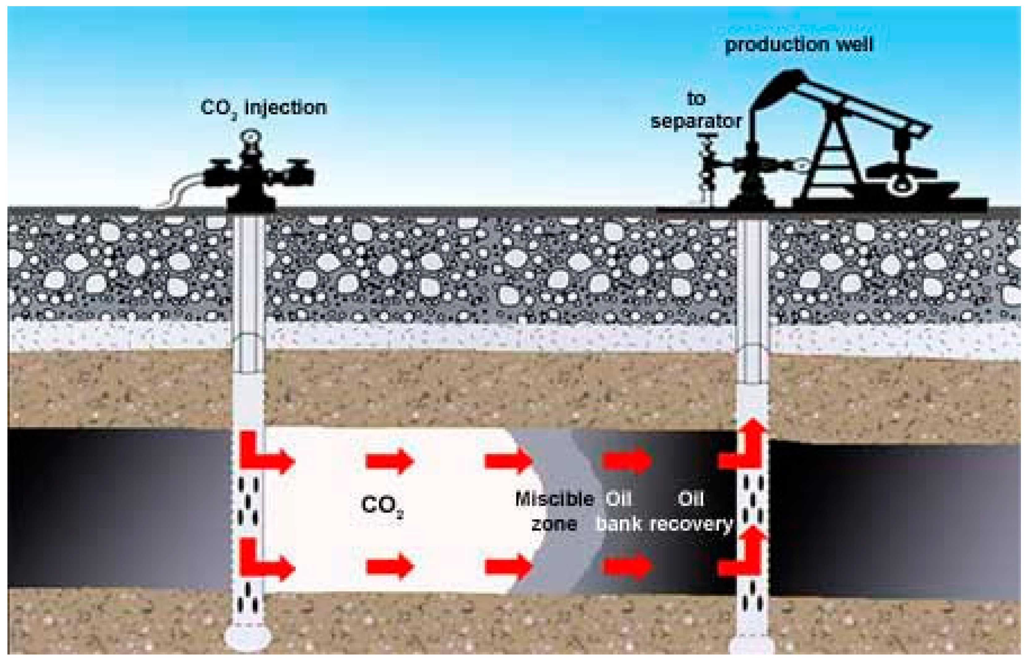
Figure 1. CO2 flooding process in oil reservoirs [22].
Energies 15 09383 g001
Figure 2. CO2 storage and uses schematic from the National Energy Technology Laboratory (NETL) [38].
Energies 15 09383 g002
Figure 3. Microstructure of reservoir rock after 70 days of corrosion [57].
Energies 15 09383 g003aEnergies 15 09383 g003b
Figure 4. Conceptual steps for CO2-EOR in fractured tight reservoirs [29]. (i) (a) oil produced by direct CO2 displacement; (ii) (b) CO2 dissolved in the crude oil caused oil swelling; (c) vaporized oil due to CO2 extraction of light and intermediate oil components; (d) coalescing of disconnected oil ganglia by oil swelling; (e) The remaining components of crude oil after vaporization; (iii) (f) the residual oil in dead-end pores after displacing a part of swollen oil by CO2; and (g) the improvement in oil recovery due to various CO2 mechanisms. The dark color and the grey color represent the original oil and the oil after interaction with the injected CO2, respectively.
Energies 15 09383 g004
Figure 5. CO2 phase diagram and the measured solubility of CO2 in the light oil sample at various pressures and different temperatures [29]: (a) CO2 phase diagram (modified after) [36,37]; (b) The measured solubility of CO2 in the light oil sample at various pressures and different temperatures [29].
Energies 15 09383 g005
Figure 6. CO2 distribution in models at different times [74].
Energies 15 09383 g006
Figure 7. Dissolution and precipitation processes during CO2 injection [76].
Energies 15 09383 g007
Figure 8. Major element concentration in the different mineral systems [94].
Energies 15 09383 g008aEnergies 15 09383 g008b
Figure 9. Organization chart of application of MD simulations in CO2 sequestration [102].
Energies 15 09383 g009
Figure 10. The non-equilibrium process is shown by CO2 mole concentration [114].
Energies 15 09383 g010
Figure 11. Schematic of the model, in which storage reservoir and aquifer are separated by caprock. A CO2 injection well is located in the center of the storage reservoir [134].
Energies 15 09383 g011
Figure 12. Machine learning training methods. Agent 1 was used to predict cumulative oil production and CO2 reserves. Training agent 2 to predict average reservoir pressure changes along the timeline [141].
Energies 15 09383 g012
Figure 13. CO2 leakage problems are caused by wellbore integrity [148].
Energies 15 09383 g013
Figure 14. Potential leakage paths of CO2 underground structure [161].
Energies 15 09383 g014
Table 1. Some ongoing and promising CO2 storage projects around the world [20].
Project SiteLocationSource of CO2Buried Body TypeThe Total Storage
Q/Mt
Storage Costs
Dollar/t
WeyburnWilliston Basin, CanadaFuel plant pipeline transportationInjection into the field to enhance oil recovery20.020
RecopolSilesian coalfield, PolandChemical plant truck canningStrengthen the exploitation of coal seam methane gas1 × 10−5-
SleipnerNorway’s north seaCO2 associated with gas fields (9.5%)Injected into the Utsira brine formation above the gas reservoir20.017
K12-BNetherlands offshore North SeaCO2 associated with gas fields (13%)Injection of waste gas reservoir to bury and inject gas field to enhance gas recovery8.07–14
InSalahCentral Algeria oil and gas fieldCO2 associated with gas fields (10%)The reservoir pressure is maintained by injecting water into the reservoir17.08
Gorgon130 km off the west coast of AustraliaCO2 associated with gas fields (14%)Injected into the LDupuy salt water layer below Barrow Island-6–10
Snohvit Barents Sea, NorwayCO2 associated with gas fields (5%~8%)Injected into the Tubasen brine formation below the gas reservoir-8
QinShui basinChina-Strengthen the exploitation of coal seam methane gas1.5 × 10−4-
Table 2. CO2 storage mechanism and main controlling factors in the oil reservoir.
Storage FormStorage MechanismMain Control Factors
Construct
storage
Part of CO2 enters the micro-pore and is permanently sealedCapillary pressure
Dissolve sequestrationCO2 partially dissolves in brine and crude oil, increasing its viscosity, volume, and storage capacityBrine salinity, Crude oil, Brine composition, Temperature, Pressure
The free storageAfter CO2 supersaturation, part of CO2 exists free. Cap layer is the key to sealingTemperature, Pressure, Rock compressibility, Cap sealing
Mineral
sequestration
CO2-formation water-rock interaction eventually consolidates as mineralsMineral composition, Reaction time, CO2 content, Temperature, Pressure
Table 3. The reported research paper on the CO2-oil interaction mechanism [29,68,69,70,71,72].
FormationMethodsCO2-Crude Oil Interaction
Mechanism
CO2-Crude Oil Interaction
Efficiency
CO2 Storage EfficiencyAuthors, Year
The fields in MalaysiaLaboratory environmentCO2 dissolution, oil viscosity reduction, oil volume expansion, interfacial tension reductionEffectiveEffectiveMohamed Gamal Rezk, 2019 [29]
Oil Reservoirs in PolandLaboratory environmentCO2 dissolutionHigh potentialEffectiveEwa Knapik, 2020 [68]
Denver Basin oil fieldsMathematical model and
numerical simulation
CO2 dissolutionEffective (106 million barrels could be produced in 22 years.)EffectiveErik Lee, 2019 [69]
Bakken tight oilNumerical simulation and
laboratory environment
CO2 dissolution, CO2-crude oil miscibleEffectiveEffective (>90%)Venkat Pranesh, 2018 [70]
Eagle Ford shale gasNumerical simulation and
laboratory environment
CO2 dissolution, CO2-crude oil miscibleEffectiveEffective (>90%)Venkat Pranesh, 2018 [70]
Changji Oilfield, XinjingMathematical model and
laboratory environment
CO2 diffusionEffective/Songyan Li, 2018 [71]
Permian BasinMathematical model and
laboratory environment
CO2 diffusionEffectiveEffective (WAG achieves a good balance between maximizing oil production and carbon monoxide)P. Hosseininoosheri, 2018 [72]
Table 4. The reported research paper on CO2-brine interaction mechanism [72,77,79,80,81,82,83].
FormationMethodsCO2-Brine Interaction
Mechanism
CO2 Storage EfficiencyAuthors, Year
Permian BasinMathematical model and
laboratory environment
CO2 diffusionEffectiveP. Hosseininoosheri, 2018 [72]
Block X of Ordos BasinNumerical simulation and
laboratory environment
CO2 diffusion, CO2-brine scalingEffectiveDongfeng Zhao, 2021 [77]
Weyburn Oil FieldLaboratory environmentCO2 dissolutionEffective (CO2 to be precipitated as calcite)S. Emberley, 2005 [79]
-Numerical simulationCO2 diffusion, CO2-brine scalingEffective (Salt precipitation is a detrimental influence)Guodong Cui, 2018 [80]
Iranian hydrocarbon reservoirLaboratory environmentCO2 dissolution and deposition
of minerals
EffectiveAmin Zandvakili, 2020 [81]
-Numerical simulationCO2 diffusion, CO2 dissolution, CO2-water-rock geochemical reactionsEffective (WAG)Guodong Cui, 2021 [82]
The hot water in the Ungaran geothermal field, Java, Indonesia.Numerical simulationCO2 diffusion, CO2-brine scalingEffective
(Achieve CO2 brine rock balance within 10 years)
Gagas Pambudi Utomo, 2021 [83]
Table 5. Summary of research on rock reaction.
AuthorSimulation MethodsResearch Content of Reacton
Iglauer S et al. [102]MDReview of CO2 reaction
Ma Z et al. [103]MDWettability estimation of different rock types
Chen C et al. [104]MDFactors on capillary capture amount
Javanbakht G et al. [105]MDThe effect of IFT
McCaughan J et al. [106]MDDifferent liquid-solid system impact
Myshakin E et al. [107]MDEffect of clay swelling
Tian Z et al. [108]LBMEffect of fluid velocity
An S et al. [109]LBMDissolution patterns under different factors
Zhang C et al. [110]LBMDifferent rock property impacting on reaction
Gao J et al. [111]LBMImpact on hydraulic property
Tian Z et al. [112]LBMConnectivity of pore channels and properties of matrix
Fazeli H et al. [113]LBMFractural formation
Chen L et al. [114]LBMNon-equilibrium process with CO2 dissolution
Dashtian H et al. [115]Pore networkEffect of two dimensionless numbers
Nghiem L et al. [117]CMGCombination of CMG-GHG
Liu D et al. [118]CMGEffect of CO2 absorption
Cui G et al. [80]CMGFactors on EOR and CCS
Graupner B J et al. [119]ECLIPSECO2 storage in deep saline aquifers
Liu H et al. [120]TOUGHREACTThe dissolution and precipitation on minerals
Publisher’s Note: MDPI stays neutral with regard to jurisdictional claims in published maps and institutional affiliations.