
Optimization of Low Salinity Water/Surfactant Flooding Design for Oil-Wet Carbonate Reservoirs by Introducing a Negative Salinity Gradient


Abstract
:1. Introduction
2. Methodology
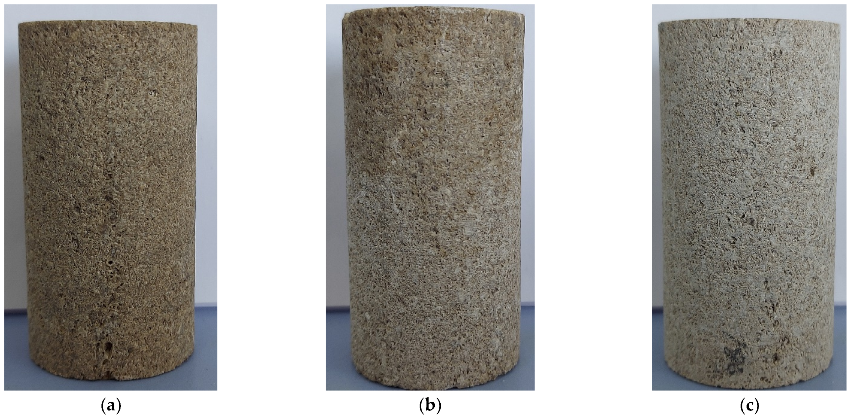
3. Rock Samples
4. Crude Oil, Brine, and Surfactant
5. Aging of Core Samples
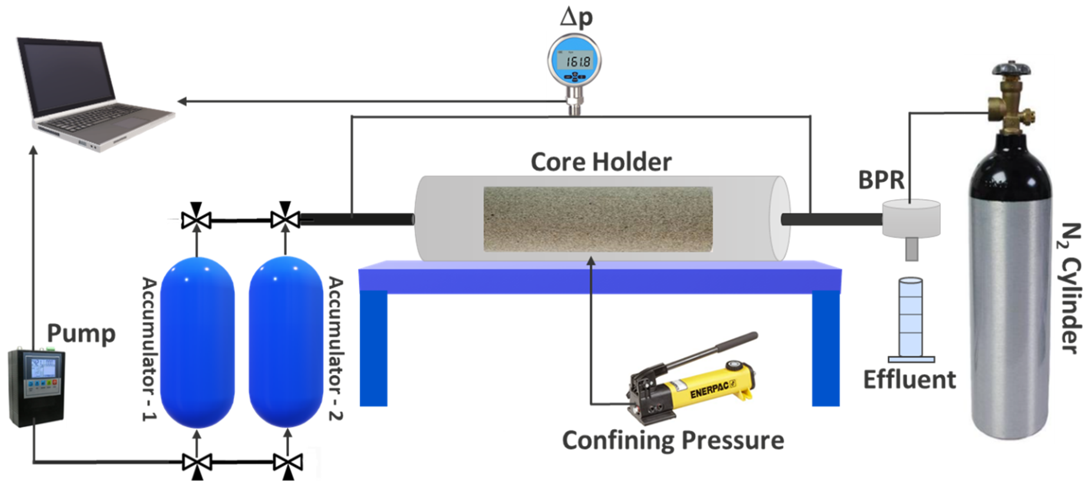
6. Coreflooding
7. Results and Discussion
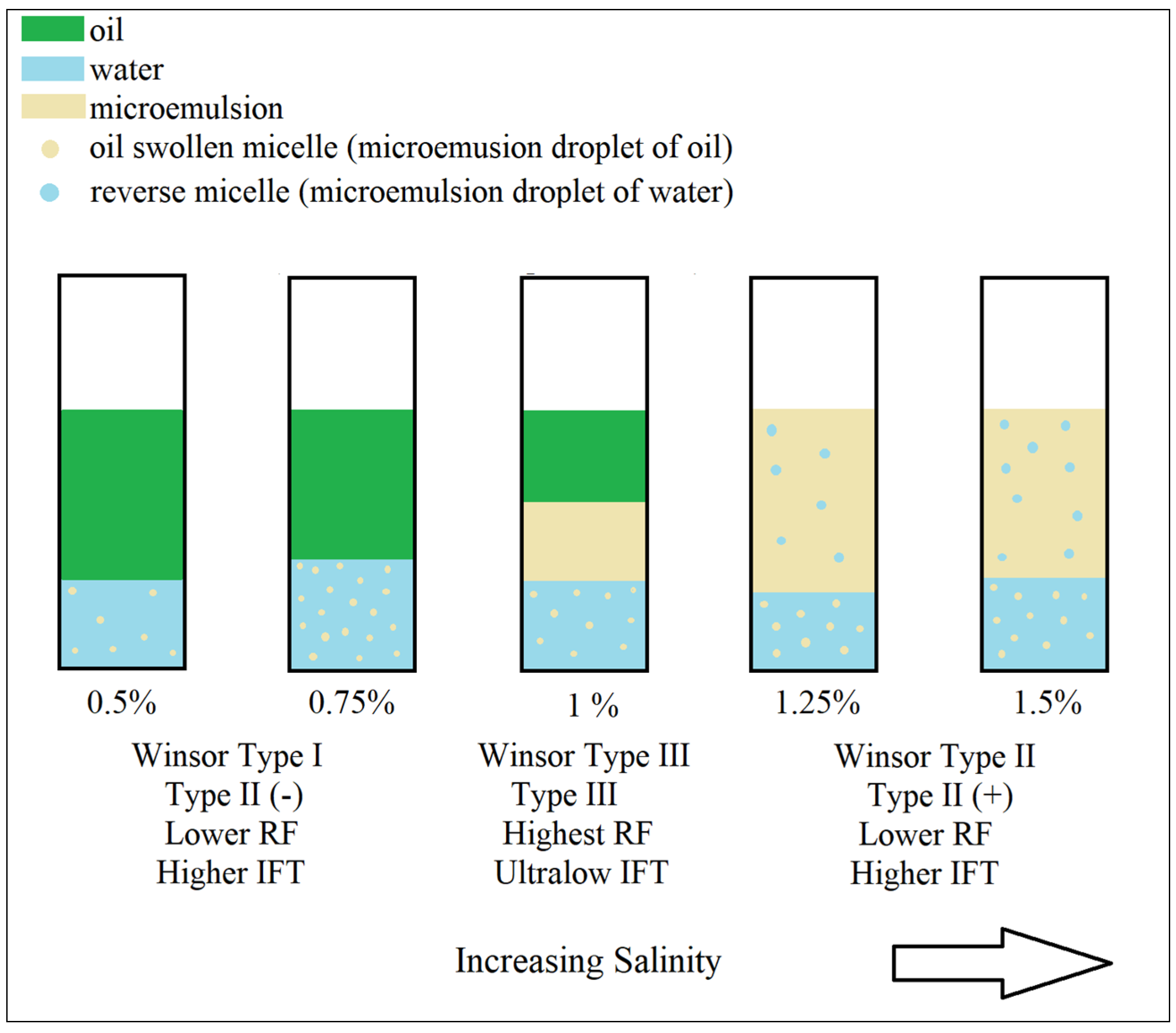
8. Aqueous Stability and Phase Behavior Results
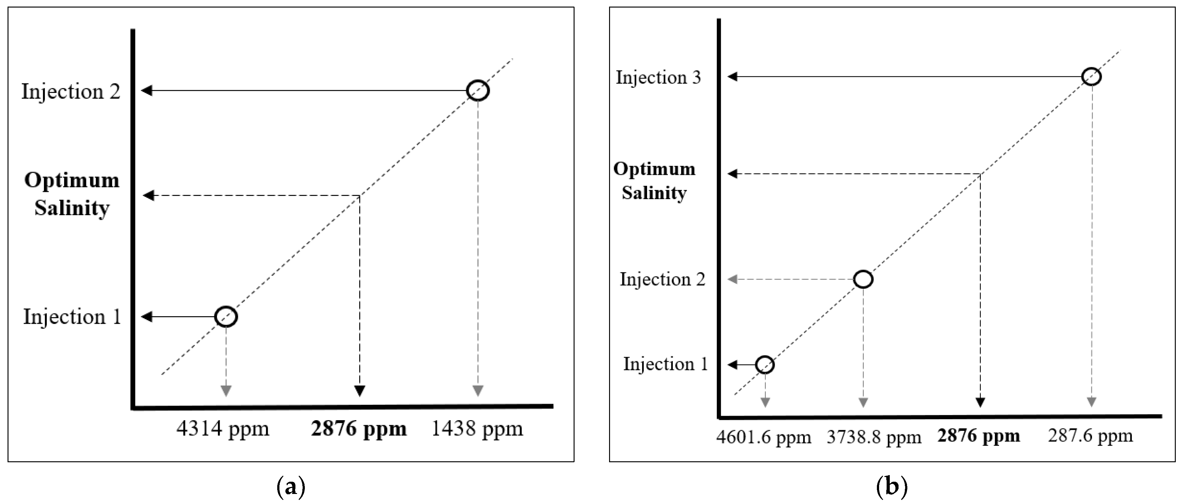
9. Negative Salinity Gradient Design
10. Coreflood Tests
10.1. Coreflood 1 (CF-1)
10.2. Coreflood-2 (CF-2)
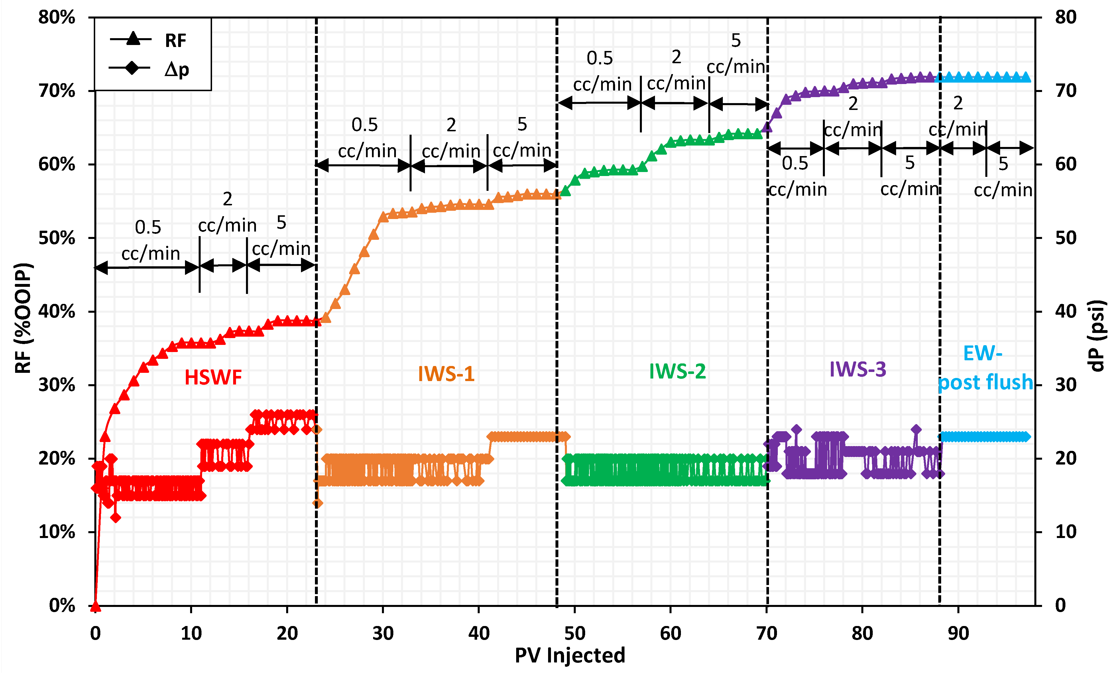
10.3. Coreflood-3 (CF-3)
11. Conclusions
Author Contributions
Funding
Acknowledgments
Conflicts of Interest
References
- Strand, S.; Høgnesen, E.J.; Austad, T. Wettability alteration of carbonates—Effects of potential determining ions (Ca2+ and SO42−) and temperature. Colloids Surf. A Physicochem. Eng. Asp. 2006, 275, 1–10. [Google Scholar] [CrossRef]
- Hiorth, A.; Cathles, L.; Madland, M. The impact of pore water chemistry on carbonate surface charge and oil wettability. Transp. Porous Media 2010, 85, 1–21. [Google Scholar] [CrossRef]
- Yousef, A.A.; Al-Saleh, S.; Al-Jawfi, M. Improved/enhanced oil recovery from carbonate reservoirs by tuning injection water salinity and ionic content. In Proceedings of the SPE Improved Oil Recovery Symposium, Tulsa, OK, USA, 14–18 April 2012. [Google Scholar]
- Ligthelm, D.J.; Gronsveld, J.; Hofman, J.; Brussee, N.; Marcelis, F.; van der Linde, H. Novel waterflooding strategy by manipulation of injection brine composition. In Proceedings of the EUROPEC/EAGE Conference and Exhibition, Amsterdam, The Netherlands, 8–11 June 2009. [Google Scholar]
- Al-Shalabi, E.W.; Sepehrnoori, K. A comprehensive review of low salinity/engineered water injections and their applications in sandstone and carbonate rocks. J. Pet. Sci. Eng. 2016, 139, 137–161. [Google Scholar] [CrossRef]
- Hosseini, E.; Chen, Z.; Sarmadivaleh, M.; Mohammadnazar, D. Applying low-salinity water to alter wettability in carbonate oil reservoirs: An experimental study. J. Pet. Explor. Prod. 2021, 11, 451–475. [Google Scholar] [CrossRef]
- Zhang, Y.; Xie, X.; Morrow, N.R. Waterflood performance by injection of brine with different salinity for reservoir cores. In Proceedings of the SPE Annual Technical Conference and Exhibition, Anaheim, CA, USA, 11–14 November 2007. [Google Scholar]
- McGuire, P.; Chatham, J.; Paskvan, F.; Sommer, D.; Carini, F. Low salinity oil recovery: An exciting new EOR opportunity for Alaska’s North Slope. In Proceedings of the SPE Western Regional Meeting, Irvine, CA, USA, 30 March–1 April 2005. [Google Scholar]
- Fathi, S.J.; Austad, T.; Strand, S. Water-based enhanced oil recovery (EOR) by “smart water”: Optimal ionic composition for EOR in carbonates. Energy Fuels 2011, 25, 5173–5179. [Google Scholar] [CrossRef] [Green Version]
- Esene, C.; Onalo, D.; Zendehboudi, S.; James, L.; Aborig, A.; Butt, S. Modeling investigation of low salinity water injection in sandstones and carbonates: Effect of Na+ and SO42−. Fuel 2018, 232, 362–373. [Google Scholar] [CrossRef]
- Shariatpanahi, S.; Hopkins, P.; Aksulu, H.; Strand, S.; Puntervold, T.; Austad, T. Water based EOR by wettability alteration in dolomite. Energy Fuels 2016, 30, 180–187. [Google Scholar] [CrossRef]
- Sheng, J.J. Status of surfactant EOR technology. Petroleum 2015, 1, 97–105. [Google Scholar] [CrossRef] [Green Version]
- Araz, A.; Kamyabi, F. Experimental study of combined low salinity and surfactant flooding effect on oil recovery. Oil Gas Sci. Technol. Rev. D’ifp Energ. Nouv. 2021, 76, 4. [Google Scholar] [CrossRef]
- Lake, L.W.; Venuto, P.B. A niche for enhanced oil recovery in the 1990s. Oil Gas J. 1990, 88, 62–67. [Google Scholar]
- Fathi, Z.; Ramirez, F.W. Optimal injection policies for enhanced oil recovery: Part 2-surfactant flooding. Soc. Pet. Eng. J. 1984, 24, 333–341. [Google Scholar] [CrossRef]
- Ahmed, S.; Elraies, K.A. Microemulsion in enhanced oil recovery. In Science and Technology Behind Nanoemulsions; BoD: Norderstedt, Germany, 2018; pp. 145–161. [Google Scholar]
- Alagic, E.; Skauge, A. Combined low salinity brine injection and surfactant flooding in mixed–wet sandstone cores. Energy Fuels 2010, 24, 3551–3559. [Google Scholar] [CrossRef]
- Alameri, W.; Teklu, T.; Graves, R.; Kazemi, H.; AlSumaiti, A. Low-salinity water-alternate-surfactant in Low-permeability Carbonate Reservoirs. In Proceedings of the IOR 2015–18th European Symposium on Improved Oil Recovery, Dresden, Germany, 14–16 April 2015; p. cp-445-00068. [Google Scholar]
- Chowdhury, S.; Shrivastava, S.; Kakati, A.; Sangwai, J.S. Comprehensive review on the role of surfactants in the chemical enhanced oil recovery process. Ind. Eng. Chem. Res. 2022, 61, 21–64. [Google Scholar] [CrossRef]
- Chen, S.; Han, M.; AlSofi, A.M.; Fahmi, M.M. Experimental evaluation of non-ionic mixed surfactant formulations at high-temperature and high-salinity conditions. J. Pet. Sci. Eng. 2022, 219, 111084. [Google Scholar] [CrossRef]
- Green, D.W.; Willhite, G.P. Enhanced Oil Recovery, 2nd ed.; Society of Petroleum Engineers (SPE): Richardson, TX, USA, 2018. [Google Scholar] [CrossRef]
- Mwangi, P.M. An Experimental Study of Surfactant Enhanced Waterflooding. Ph.D. Thesis, University of Rochester, Rochester, NY, USA, 2010. [Google Scholar]
- Nelson, R.; Pope, G. Phase relationships in chemical flooding. Soc. Pet. Eng. J. 1978, 18, 325–338. [Google Scholar] [CrossRef]
- Isaac, O.T.; Pu, H.; Oni, B.A.; Samson, F.A. Surfactants employed in conventional and unconventional reservoirs for enhanced oil recovery—A review. Energy Rep. 2022, 8, 2806–2830. [Google Scholar] [CrossRef]
- Kharrat, A.; Brandstätter, B.; Borji, M.; Ritter, R.; Arnold, P.; Fritz-Popovski, G.; Paris, O.; Ott, H. Development of foam-like emulsion phases in porous media flow. J. Colloid Interface Sci. 2022, 608, 1064–1073. [Google Scholar] [CrossRef]
- Javadi, A.H.; Fatemi, M. Impact of salinity on fluid/fluid and rock/fluid interactions in enhanced oil recovery by hybrid low salinity water and surfactant flooding from fractured porous media. Fuel 2022, 329, 125426. [Google Scholar] [CrossRef]
- Obisesan, O.; Ahmed, R.; Amani, M. The effect of salt on stability of aqueous foams. Energies 2021, 14, 279. [Google Scholar] [CrossRef]
- Novosad, J. Surfactant retention in Berea sandstone—Effects of phase behavior and temperature. Soc. Pet. Eng. J. 1982, 22, 962–970. [Google Scholar] [CrossRef]
- Kamal, M.S.; Hussein, I.A.; Sultan, A.S. Review on surfactant flooding: Phase behavior, retention, IFT, and field applications. Energy Fuels 2017, 31, 7701–7720. [Google Scholar] [CrossRef]
- Liu, Z.; Zhao, G.; Brewer, M.; Lv, Q.; Sudhölter, E.J. Comprehensive review on surfactant adsorption on mineral surfaces in chemical enhanced oil recovery. Adv. Colloid Interface Sci. 2021, 294, 102467. [Google Scholar] [CrossRef] [PubMed]
- Podoprigora, D.; Byazrov, R.; Sytnik, J. The Comprehensive Overview of Large-Volume Surfactant Slugs Injection for Enhancing Oil Recovery: Status and the Outlook. Energies 2022, 15, 8300. [Google Scholar] [CrossRef]
- Amirmoshiri, M.; Zhang, L.; Puerto, M.C.; Tewari, R.D.; Bahrim, R.Z.B.K.; Farajzadeh, R.; Hirasaki, G.J.; Biswal, S.L. Role of wettability on the adsorption of an anionic surfactant on sandstone cores. Langmuir 2020, 36, 10725–10738. [Google Scholar] [CrossRef]
- Liu, S.; Li, R.F.; Miller, C.A.; Hirasaki, G.J. Alkaline/surfactant/polymer processes: Wide range of conditions for good recovery. SPE J. 2010, 15, 282–293. [Google Scholar] [CrossRef] [Green Version]
- Meyers, K.O.; Salter, S.J. The effect of oil/brine ratio on surfactant adsorption from microemulsion. Soc. Pet. Eng. J. 1981, 21, 500–512. [Google Scholar] [CrossRef]
- Yao, Y.; Wei, M.; Kang, W. A review of wettability alteration using surfactants in carbonate reservoirs. Adv. Colloid Interface Sci. 2021, 294, 102477. [Google Scholar] [CrossRef]
- Pourafshary, P.; Moradpour, N. Hybrid EOR methods utilizing low-salinity water. Enhanc. Oil Recovery Process. New Technol. 2019, 8, 25. [Google Scholar]
- Zivar, D.; Pourafshary, P.; Moradpour, N. Capillary desaturation curve: Does low salinity surfactant flooding significantly reduce the residual oil saturation? J. Pet. Explor. Prod. 2021, 11, 783–794. [Google Scholar] [CrossRef]
- Shi, Y.; Miller, C.; Mohanty, K. Surfactant-Aided Low-Salinity Waterflooding for Low-Temperature Carbonate Reservoirs. SPE J. 2021, 26, 2214–2230. [Google Scholar] [CrossRef]
- Kokal, S.; Al-Kaabi, A. Enhanced oil recovery: Challenges & opportunities. World Pet. Counc. Off. Publ. 2010, 64, 64–69. [Google Scholar]
- Shaddel, S.; Tabatabae-Nejad, S. Alkali/surfactant improved low-salinity waterflooding. Transp. Porous Media 2015, 106, 621–642. [Google Scholar] [CrossRef]
- Hosseinzade Khanamiri, H.; Baltzersen Enge, I.; Nourani, M.; Stensen, J.Å.; Torsæter, O.; Hadia, N. EOR by low salinity water and surfactant at low concentration: Impact of injection and in situ brine composition. Energy Fuels 2016, 30, 2705–2713. [Google Scholar] [CrossRef]
- Alagic, E.; Spildo, K.; Skauge, A.; Solbakken, J. Effect of crude oil ageing on low salinity and low salinity surfactant flooding. J. Pet. Sci. Eng. 2011, 78, 220–227. [Google Scholar] [CrossRef]
- Johannessen, A.M.; Spildo, K. Enhanced oil recovery (EOR) by combining surfactant with low salinity injection. Energy Fuels 2013, 27, 5738–5749. [Google Scholar] [CrossRef]
- Todd, M.; Dietrich, J.; Goldburg, A.; Larson, R. Numerical simulation of competing chemical flood designs. In Proceedings of the SPE Symposium on Improved Methods of Oil Recovery, Tulsa, OK, USA, 16–17 April 1978. [Google Scholar]
- Sheng, J.J. Modern Chemical Enhanced Oil Recovery: Theory and Practice; Gulf Professional Publishing: Houston, TX, USA, 2010. [Google Scholar]
- Gogarty, W. Status of surfactant or micellar methods. J. Pet. Technol. 1976, 28, 93–102. [Google Scholar] [CrossRef]
- Murtada, H.; Marx, C. Evaluation of the Low Tension Flood Process for High-Salinity Reservoirs—Laboratory Investigation Under Reservoir Conditions. Soc. Pet. Eng. J. 1982, 22, 831–846. [Google Scholar] [CrossRef]
- Tavassoli, S.; Korrani, A.K.; Pope, G.A.; Sepehrnoori, K. Low-salinity surfactant flooding—A multimechanistic enhanced-oil-recovery method. SPE J. 2016, 21, 0744–0760. [Google Scholar] [CrossRef]
- Tahir, M.; Hincapie, R.E.; Foedisch, H.; Abdullah, H.; Ganzer, L. Impact of sulphates presence during application of smart water flooding combined with polymer flooding. In Proceedings of the SPE Europec Featured at 80th EAGE Conference and Exhibition, Copenhagen, Denmark, 11–14 June 2018. [Google Scholar]
- Hosseini-Nasab, S.M.; Padalkar, C.; Battistutta, E.; Zitha, P. Mechanistic modeling of the alkaline/surfactant/polymer flooding process under sub-optimum salinity conditions for enhanced oil recovery. Ind. Eng. Chem. Res. 2016, 55, 6875–6888. [Google Scholar] [CrossRef]
- Zhou, H.; Davarpanah, A. Hybrid chemical enhanced oil recovery techniques: A simulation study. Symmetry 2020, 12, 1086. [Google Scholar] [CrossRef]
- Hu, Y.; Cheng, Q.; Yang, J.; Zhang, L.; Davarpanah, A. A laboratory approach on the hybrid-enhanced oil recovery techniques with different saline brines in sandstone reservoirs. Processes 2020, 8, 1051. [Google Scholar] [CrossRef]
- Hirasaki, G.J.; Miller, C.A.; Puerto, M. Recent advances in surfactant EOR. SPE J. 2011, 16, 889–907. [Google Scholar] [CrossRef]
- Jackson, M.; Vinogradov, J.; Hamon, G.; Chamerois, M. Evidence, mechanisms and improved understanding of controlled salinity waterflooding part 1: Sandstones. Fuel 2016, 185, 772–793. [Google Scholar] [CrossRef] [Green Version]
- Myint, P.C.; Firoozabadi, A. Thin liquid films in improved oil recovery from low-salinity brine. Curr. Opin. Colloid Interface Sci. 2015, 20, 105–114. [Google Scholar] [CrossRef] [Green Version]
- Hirasaki, G.J. Application of the theory of multicomponent, multiphase displacement to three-component, two-phase surfactant flooding. Soc. Pet. Eng. J. 1981, 21, 191–204. [Google Scholar] [CrossRef]
- Park, S.W.; Lee, J.; Yoon, H.; Shin, S. Microfluidic investigation of salinity-induced oil recovery in porous media during chemical flooding. Energy Fuels 2021, 35, 4885–4892. [Google Scholar] [CrossRef]
- Nelson, R.C. The salinity-requirement diagram—A useful tool in chemical flooding research and development. Soc. Pet. Eng. J. 1982, 22, 259–270. [Google Scholar] [CrossRef]
- Maurya, N.K.; Mandal, A. Investigation of synergistic effect of nanoparticle and surfactant in macro emulsion based EOR application in oil reservoirs. Chem. Eng. Res. Des. 2018, 132, 370–384. [Google Scholar] [CrossRef]
- Pope, G.; Wang, B.; Tsaur, K. A sensitivity study of micellar/polymer flooding. Soc. Pet. Eng. J. 1979, 19, 357–368. [Google Scholar] [CrossRef]
- Tabary, R.; Bazin, B.; Douarche, F.; Moreau, P.; Oukhemanou-Destremaut, F. Surfactant flooding in challenging conditions: Towards hard brines and high temperatures. In Proceedings of the SPE Middle East Oil and Gas Show and Conference, Manama, Bahrain, 10–13 March 2013. [Google Scholar]
- Gupta, S.P.; Trushenski, S.P. Micellar flooding-compositional effects on oil displacement. Soc. Pet. Eng. J. 1979, 19, 116–128. [Google Scholar] [CrossRef]
- Molinier, V.; Klimenko, A.; Passade-Boupat, N.; Bourrel, M. Insights into the Intimate Link between the Surfactant/Oil/Water Phase Behavior and the Successful Design of (Alkali)–Surfactant–Polymer Floods. Energy Fuels 2021, 35, 20046–20059. [Google Scholar] [CrossRef]
- Huh, C. Interfacial tensions and solubilizing ability of a microemulsion phase that coexists with oil and brine. J. Colloid Interface Sci. 1979, 71, 408–426. [Google Scholar] [CrossRef]
- Sui, X.; Chen, Z.; Kurnia, I.; Han, X.; Yu, J.; Zhang, G. Alkaline-surfactant-polymer flooding of active oil under reservoir conditions. Fuel 2020, 262, 116647. [Google Scholar] [CrossRef]
- Chen, Z.; Han, X.; Kurnia, I.; Yu, J.; Zhang, G.; Li, L. Adoption of phase behavior tests and negative salinity gradient concept to optimize Daqing oilfield alkaline-surfactant-polymer flooding. Fuel 2018, 232, 71–80. [Google Scholar] [CrossRef]
- Han, X.; Chen, Z.; Zhang, G.; Yu, J. Surfactant-polymer flooding formulated with commercial surfactants and enhanced by negative salinity gradient. Fuel 2020, 274, 117874. [Google Scholar] [CrossRef]
- Han, X.; Kurnia, I.; Chen, Z.; Yu, J.; Zhang, G. Effect of oil reactivity on salinity profile design during alkaline-surfactant-polymer flooding. Fuel 2019, 254, 115738. [Google Scholar] [CrossRef]
- Isabaev, Y. Chemical Composition and Properties of Formation Water Oil and Gas West Kazakhstan. Her. Kazakh-Br. Tech. Univ. 2015, 12, 3. [Google Scholar]
- Shakeel, M.; Pourafshary, P.; Hashmet, M.R. Effect of Initial Wettability on Capillary Desaturation by Hybrid Engineered Water/Polymer Flooding in Carbonate Reservoirs. In Proceedings of the 8th World Congress on Mechanical, Chemical, and Material Engineering, Prague, Czech Republic, 31 July–2 August 2022. [Google Scholar]
- Sekerbayeva, A.; Pourafshary, P.; Hashmet, M.R. Application of anionic Surfactant/Engineered water hybrid EOR in carbonate formations: An experimental analysis. Petroleum 2020, 1, 1–12. [Google Scholar] [CrossRef]
- Karimov, D.; Hashmet, M.R.; Pourafshary, P. A Laboratory Study to Optimize Ion Composition for the Hybrid Low Salinity Water/Polymer Flooding. In Proceedings of the Offshore Technology Conference Asia, Kuala Lumpur, Malaysia, 2–6 November 2020. [Google Scholar]
- Ma, K.; Cui, L.; Dong, Y.; Wang, T.; Da, C.; Hirasaki, G.J.; Biswal, S.L. Adsorption of cationic and anionic surfactants on natural and synthetic carbonate materials. J. Colloid Interface Sci. 2013, 408, 164–172. [Google Scholar] [CrossRef]
- Singh, R.; Mohanty, K.K. Foams with wettability-altering capabilities for oil-wet carbonates: A synergistic approach. SPE J. 2016, 21, 1126–1139. [Google Scholar] [CrossRef]
- AlSofi, A.M.; Wang, J.; AlBoqmi, A.M.; AlOtaibi, M.B.; Ayirala, S.C.; AlYousef, A.A. Smartwater synergy with chemical enhanced oil recovery: Polymer effects on smartwater. SPE Reserv. Eval. Eng. 2019, 22, 61–77. [Google Scholar] [CrossRef]
- Lake, L.W. Enhanced Oil Recovery; Prentice Hall: Englewood Cliffs, NJ, USA, 1989. [Google Scholar]
- Shakeel, M.; Samanova, A.; Pourafshary, P.; Hashmet, M.R. Experimental analysis of oil displacement by hybrid engineered water/chemical EOR approach in carbonates. J. Pet. Sci. Eng. 2021, 207, 109297. [Google Scholar] [CrossRef]
- Glover, C.; Puerto, M.; Maerker, J.; Sandvik, E. Surfactant phase behavior and retention in porous media. Soc. Pet. Eng. J. 1979, 19, 183–193. [Google Scholar] [CrossRef]
- Shakeel, M.; Pourafshary, P.; Rehan Hashmet, M. Hybrid Engineered Water–Polymer Flooding in Carbonates: A Review of Mechanisms and Case Studies. Appl. Sci. 2020, 10, 6087. [Google Scholar] [CrossRef]
- Kakati, A.; Sangwai, J.S. Low Salinity Surfactant Flooding: Role of Surfactant and Salt. In Surfactants in Upstream E&P; Solling, T., Shahzad Kamal, M., Shakil Hussain, S.M., Eds.; Springer International Publishing: Cham, Switzerland, 2021; pp. 225–243. [Google Scholar]
- Austad, T.; Shariatpanahi, S.; Strand, S.; Black, C.; Webb, K. Conditions for a low-salinity enhanced oil recovery (EOR) effect in carbonate oil reservoirs. Energy Fuels 2012, 26, 569–575. [Google Scholar] [CrossRef]
- Ebaga-Ololo, J.; Chon, B.H. Experimental investigation of the influence of salinity gradient on low-concentration surfactant flooding in Berea sandstone. J. Ind. Eng. Chem. 2018, 68, 355–363. [Google Scholar] [CrossRef]
- Riswati, S.S.; Bae, W.; Park, C.; Permadi, A.K.; Efriza, I.; Min, B. Experimental analysis to design optimum phase type and salinity gradient of Alkaline Surfactant Polymer flooding at low saline reservoir. J. Pet. Sci. Eng. 2019, 173, 1005–1019. [Google Scholar] [CrossRef]
- Adams, W.T.; Schievelbein, V.H. Surfactant flooding carbonate reservoirs. SPE Reserv. Eng. 1987, 2, 619–626. [Google Scholar] [CrossRef]
- Martin, F.; Oxley, J.; Lim, H. Enhanced recovery of a J sand crude oil with a combination of surfactant and alkaline chemicals. In Proceedings of the SPE Annual Technical Conference and Exhibition, Las Vegas, NV, USA, 22–26 September 1985. [Google Scholar]


| Sample # | Diameter (mm) | Length (mm) | Dry Weight (g) | Porosity (%) |
|---|---|---|---|---|
| Core-1 | 38.06 | 73.03 | 185.54 | 16.02 |
| Core-2 | 38.10 | 73.00 | 187.70 | 14.63 |
| Core-3 | 38.10 | 73.06 | 186.81 | 14.47 |
| Ions | Formation Water (FW) | South Caspian Sea (HSW) | Optimized Engineered Water (EW) |
|---|---|---|---|
| ppm | |||
| Na+ + K+ | 81,600 | 3240 | 325 |
| Ca2+ | 9540 | 350 | 105 |
| Mg2+ | 1470 | 740 | 74 |
| Cl− | 90,370 | 5440 | 544 |
| SO42− | - | 3010 | 1806 |
| HCO3− | - | 220 | 22 |
| Total | 181,980 | 13,000 | 2876 |
| Absolute Permeability (mD) | Effective Permeability (mD) | Swi | |
|---|---|---|---|
| Core-1 | 94.04 | 90.17 | 0.19 |
| Core-2 | 163.87 | 112.55 | 0.12 |
| Core-3 | 117.09 | 111.54 | 0.12 |
| Ions | Optimum Engineered Water, ppm | CF-2 | CF-3 | |||
|---|---|---|---|---|---|---|
| Injection 1 (ppm) | Injection 2 (ppm) | Injection 1 (ppm) | Injection 2 (ppm) | Injection 3 (ppm) | ||
| Na+ + K+ | 325 | 487.5 | 162.5 | 520 | 422.5 | 32.5 |
| Ca2+ | 105 | 157.5 | 52.5 | 168 | 136.5 | 10.5 |
| Mg2+ | 74 | 111 | 37 | 118.4 | 96.2 | 7.4 |
| Cl− | 544 | 816 | 272 | 870.4 | 707.2 | 54.4 |
| SO42− | 1806 | 2709 | 903 | 2889.6 | 2347.8 | 180.6 |
| HCO3− | 22 | 33 | 11 | 35.2 | 28.6 | 2.2 |
| Total | 2876 | 4314 | 1438 | 4601.6 | 3738.8 | 287.6 |
| Test ID | Injection Design | Injection Fluid Details | Emulsion Type |
|---|---|---|---|
| 1. CF-1 | HSW > EW > EWSF | HSW—Caspian Sea water | |
| EW—Engineered water | |||
| EWSF—Engineered water with a surfactant of 1 wt% concentration | III-III | ||
| 2. CF-2 | HSW > IWS-1 > IWS-2 > LSW | HSW—Caspian Sea water | |
| IWS-1—Injection 1 with a surfactant of 1 wt% concentration | II | ||
| IWS-2—Injection 2 with a surfactant of 1 wt% concentration | III-I | ||
| 3. CF-3 | HSW > IWS-1 > IWS-2 > IWS-3 > LSW | HSW—Caspian Sea water | |
| IWS-1—Injection 1 with a surfactant of 1 wt% concentration | II | ||
| IWS-2—Injection 2 with a surfactant of 1 wt% concentration | II | ||
| IWS-3—Injection 3 with a surfactant of 1 wt% concentration | III-I |
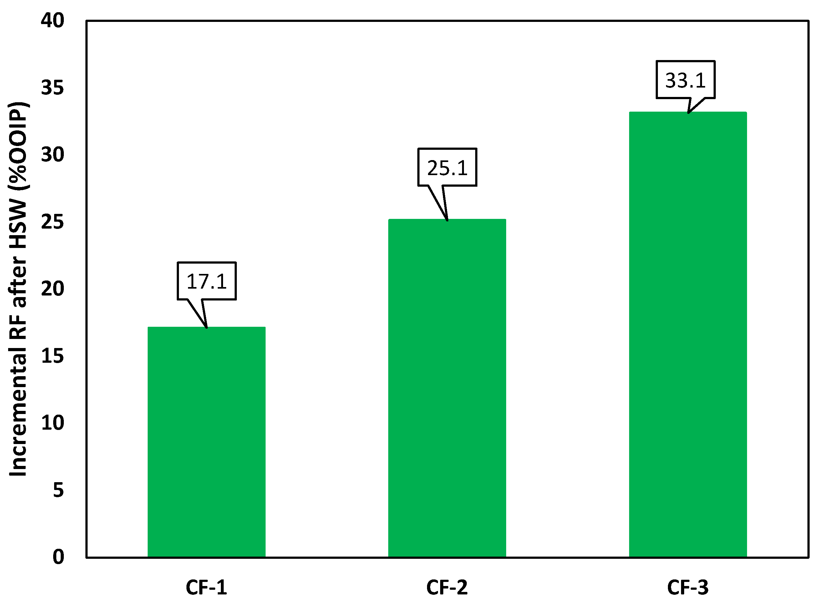
| Test ID | Process | Total | ||||
|---|---|---|---|---|---|---|
| HSW | EWF | EWSF | ||||
| CF-1 (Constant salinity profile) | RF (%OOIP) | 65.4 | 71.5 | 82.5 | ||
| Inc. RF | - | 6.1 | 11.0 | 17.1 | ||
| RF (%ROIC) | 65.4 | 17.6 | 38.7 | |||
| CF-2 (Sharp negative salinity gradient) | HSW | IWS-1 | IWS-2 | |||
| RF (%OOIP) | 41.3 | 55.9 | 66.4 | |||
| Inc. RF | - | 14.6 | 10.5 | 25.1 | ||
| RF (%ROIC) | 41.2 | 24.9 | 23.8 | |||
| CF-3 (Gradual negative salinity gradient) | HSW | IWS-1 | IWS-2 | IWS-3 | ||
| RF (%OOIP) | 38.8 | 56.0 | 64.2 | 72.0 | ||
| Inc. RF | - | 17.2 | 8.2 | 7.7 | 33.1 | |
| RF (%ROIC) | 38.8 | 28.2 | 18.6 | 21.6 | ||
Publisher’s Note: MDPI stays neutral with regard to jurisdictional claims in published maps and institutional affiliations. |
© 2022 by the authors. Licensee MDPI, Basel, Switzerland. This article is an open access article distributed under the terms and conditions of the Creative Commons Attribution (CC BY) license (https://creativecommons.org/licenses/by/4.0/).
Share and Cite
Shakeel, M.; Samanova, A.; Pourafshary, P.; Hashmet, M.R. Optimization of Low Salinity Water/Surfactant Flooding Design for Oil-Wet Carbonate Reservoirs by Introducing a Negative Salinity Gradient. Energies 2022, 15, 9400. https://doi.org/10.3390/en15249400
Shakeel M, Samanova A, Pourafshary P, Hashmet MR. Optimization of Low Salinity Water/Surfactant Flooding Design for Oil-Wet Carbonate Reservoirs by Introducing a Negative Salinity Gradient. Energies. 2022; 15(24):9400. https://doi.org/10.3390/en15249400
Chicago/Turabian StyleShakeel, Mariam, Aida Samanova, Peyman Pourafshary, and Muhammad Rehan Hashmet. 2022. "Optimization of Low Salinity Water/Surfactant Flooding Design for Oil-Wet Carbonate Reservoirs by Introducing a Negative Salinity Gradient" Energies 15, no. 24: 9400. https://doi.org/10.3390/en15249400
APA StyleShakeel, M., Samanova, A., Pourafshary, P., & Hashmet, M. R. (2022). Optimization of Low Salinity Water/Surfactant Flooding Design for Oil-Wet Carbonate Reservoirs by Introducing a Negative Salinity Gradient. Energies, 15(24), 9400. https://doi.org/10.3390/en15249400