Article

Underwater Wireless Charging System of Unmanned Surface Vehicles with High Power, Large Misalignment Tolerance and Light Weight: Analysis, Design and Optimization

1
Southern University of Science and Technology Jiaxing Research Institute, Jiaxing 314000, China
2
Department of Electronic and Electrical Engineering, Southern University of Science and Technology, Shenzhen 518055, China
3
Department of Electrical Engineering, The Hong Kong Polytechnic University, Kowloon, Hong Kong, China
*
Author to whom correspondence should be addressed.
Energies 2022, 15(24), 9529; https://doi.org/10.3390/en15249529
Submission received: 22 November 2022 / Revised: 6 December 2022 / Accepted: 12 December 2022 / Published: 15 December 2022

Abstract

:
Wireless charging systems (WCSs) are considered very appropriate to recharge underwater surface vehicles (USVs) due to their safe, flexible, and cost-effective characteristics. The small depth of immersion of USVs allows a WCS operated at an mm-level distance using a dock. Resultant tight coupling between the transmitter and receiver is conducive to high power, yet faces a challenge to alleviating misalignment sensitivity. In addition, considering USVs’ endurance, the weight of a WCS should be strictly limited. In this paper, a 6.0 kW underwater WCS is analyzed, designed, and optimized, which achieves a good balance of power capacity, misalignment tolerance, and onboard weight. A multi-receiving-coil structure is employed, which is crucial to large misalignment tolerance. On this basis, two types of coils adapting the hull shape of USV, viz., curved and quasi-curved coils, are devised and compared in case the hydrodynamic performance of USV is degraded. Finally, the weight of receiver is effectively reduced using bar-shaped ferrite without sacrificing the power capacity of WCSs. The results indicate a merely 8.73% drop in coupling coefficient with misalignment ranging from 0 to 100 mm. Moreover, ferrite use is reduced by 40.48 kg compared to a ferrite sheet, which accounts for 50.28% weight of the receiver.

1. Introduction

Unmanned surface vehicles (USVs) are water-borne vessels that are able to operate on the surface of water with no crew involved. Their applications can be traced back to World War II, such as target crafts that are controlled remotely and manually. In recent years, higher and higher levels of autonomous driving have enabled the upgrade of control methods from remote control to full autonomy. In this context, the scope of USVs’ applications is expanded to environmental inspection, hydrographic survey, flood rescue, etc. [1,2,3]. Typically, USVs are energized by onboard batteries. However, battery capacity is very limited, since USVs are of small size, and their hydrodynamic performances are very sensitive to the payload. Without any doubt, this deficiency will degenerate their endurance. Therefore, it is a pressing need to charge a USV in an underwater environment in an automated, safe, and high-power manner.
Currently, underwater charging methods include conductive charging, batter swap, and wireless charging. There is no doubt that conductive charging is dominant in terrestrial applications with the virtue of its high technical maturity and cost-effectiveness. However, this contact-based method might be dangerous due to electrical leakage. The wet-mate connector is a solution to this problem, yet it is too expensive [4]. In addition, automated conductive charging cannot be achieved without high-precision alignment tools, which is very complex and definitely further brings cost. According to our investigation of USV enterprises, battery swap is actually a more common choice in practice [5]. Its comparative advantage mainly lies in improved safety dispensed with underwater operation. Nevertheless, this method usually needs crew participation. If unmanned, a set of special-designed, auxiliary, and complicated swapping system is necessary for specific types of USVs and batteries. Such a system without broad applicability is not feasible, especially in the context where USVs have not been as popular as electric vehicles.
As a safe, cost-effective, and broadly applicable method, underwater wireless charging technology is considered highly suitable for USVs. It not only eliminates electrical leakage hazards relying on its contactless characteristics, but also facilitates autonomous operation due to relatively simple requirements when aligning the transmitter and receiver of an underwater wireless charging system (UWCS). Categorized by power transmission mechanism, UWCS can be roughly realized by inductive coupling or capacitive coupling. A capacitive power transmission (CPT) system is usually constructed with a pair of coupling capacitors. CPT is more viable for low-power applications due to the constraints on developed voltage and coupling capacitance [6]. Moreover, as demonstrated in [7,8], the operation frequency of CPT systems reaches hundreds of kHz, which is not conducive to the control of power loss. By contrast, inductive power transmission (IPT) is more accepted underwater. Adopting the law of electromagnetic induction, IPT systems can operate with relatively low frequency (tens of kHz) and sufficient coupling [9]. Therefore, IPT systems can achieve a better balance of efficiency and power capacity. In what follows, the design of UWCS will be based on IPT.
The concept of underwater wireless power transfer (UWPT) is first proposed by Heeres et al. [10]. The proposed design uses a linear coaxial winding transformer distanced by an mm-level air gap, which can maintain 2.5 kW output power with 85% efficiency in seawater. Most recently, UWPT has been attracting more and more attention. Its applications range from tens to thousands of watts [11,12,13,14,15,16,17,18,19,20,21]. In [11], four pairs of EE-core-based coils are incorporated into a UWCS with its output power ranging from 250 W to 1700 W. At-sea trials of this design are performed successively in three different types of underwater vehicles of Battelle memorial institute. Considering the very limited assembly space and payload of underwater vehicles, the mainstream coupling coils are lightweight, which are typically broad and thin rather than of considerable thickness, such as the EE shape. In [12], a 1 × 1 × 1 structure of transmitting (Tx) coils is proposed, which means two Tx coils are placed symmetrically adjacent to each side of the receiving (Rx) coil connected to the moorings of the vehicle. It is reported that the power loss associated with this structure is smaller than that of a one-transmitter-one-receiver structure on the premise of the air core. Unfortunately, in the lack of a magnetic core, the experimental efficiency is smaller than 80%. In [13], to match the shape of underwater vehicles, curved coils were devised. On this basis, two coil topologies, i.e., unipolar and bipolar coils, are compared from the perspective of magnetic coupling. The results reflect that bipolar coils surpass the other with the maximum efficiency of UWCS reaching 95% under the 1 kW rated output condition. Similarly, curved coils are also preferred by [14]. This work is mainly aimed at electromagnetic protection for the onboard electronics of an underwater vehicle. To be specific, a dipole-coil-based magnetic coupler with a novel circumferential coupling manner is designed so that the magnetic flux can be well confined. The output power and dc-dc efficiency of the dipole-coil-based charging system are separately 630 W and 89.7%.
Another practical issue needing special attention is the misalignment between Tx and Rx coils, which can hardly be avoided. Moreover, the misalignment is not stationary since the underwater environment is not as stable as air. In [15], a uniform magnetic field distribution is secured in the charging area by a novel hybrid transmitter composed of conical and planar spiral coils. The concept of field shaping realizes 86% efficiency stably in a 0–100 mm misalignment area with a transfer distance of 20 mm. Refs. [16,17] express their concern about rotational misalignment, which is not common in terrestrial applications. The worst-case tests of corresponding UWCS demonstrate the efficiency of 71.77% and 86.19%, respectively. There are some other works taking different physical properties of seawater, fresh water, and air into account, which might influence power and data transfer deeply. To discover how different power transmission media influence the performance of UWCSs, a comparative analysis of power loss is conducted with all modules fully considered, including the power amplifier stage, coils and compensation capacitor, magnetic core, medium, and rectifier stage [18], a novel power distribution model is established by converting the eddy-current loss in seawater into an individual impedance [19], an attenuation model in seawater is built to find the optimal range of coupling coefficient [20], and a frequency-sensitivity analysis is carried out for the purpose of higher dc-dc efficiency in seawater [21].
The underwater charging technology for USVs, which is caught a focus by this paper, is indeed a branch of generalized UWPT. Therefore, there are some common challenges that USVs also have to face, as previously analyzed. For example, large misalignment tolerance should be achieved unless a high-precision alignment between Tx and Rx coils is easy to implement. Note that, according to practical scenarios, USVs simply need to handle horizontal misalignment. That is to say, the rotational counterpart does not exist, which will be further explained in Section 2. Moreover, USVs also share the goal of lightweight UWCS for a hydrodynamic reason. As for the issues such as waterproofing, pressure tolerant electronics, and electromagnetic protection, these are more engineering considerations, which will not be detailed in this paper.
There are also some particular challenges to recharging a USV. As the name of USV implies, its depth of immersion is very small. Therefore, with the help of a dock system, it can be recharged easily under tight-coupling conditions, no matter whether the receiver of a UWCS is installed at either the bottom or prow of a USV [22]. On the one hand, this is technically conducive to realizing high-power charging. On the other hand, for small-distance charging applications, a series of problems arising from frequency splitting and misalignment sensitivity are especially difficult to address. To summarize, in this paper, a 6.0-kW high-power underwater wireless charging system, supported by a dock system, is proposed to fulfill various requirements of USV in practice. Large misalignment tolerance is the design goal of top priority. This is achieved by a compact design of a multi-Rx coil structure with the shape of transmitter, the topology of Rx coils, and the number of units of Rx coils comprehensively considered. Parallel operation of two sets of circuits is employed to double the output power while realizing satisfied heat management and electromagnetic safety. On this basis, two types of coils for adapting the hull shape of USV, viz., curved coils and quasi-curved coils, are devised and compared with their chord heights optimized. Finally, the weight of Rx coils is effectively reduced using bar-shaped ferrite without sacrificing the power capacity of UWCS.

2. System Configuration

An overview of the proposed UWCS is depicted in Figure 1. As shown in Figure 1a, this UWCS consists of an ancillary dock system, two transmitters on the dock side, and two receivers on the USV side. The function of the dock system is to bring the USV to the shore and then commence the charging process. As the key component of UWCS, the Rx limiter can guarantee the spatial misalignment between transmitter and receiver within a specified range in case the interoperability of double sides gets lost. The exploded view of transmitters and receivers is shown in Figure 1b, which exhibits a compact characteristic. On the Tx side, Rx limiter serves as not only a container for Tx coils, but also an object of the same shape to fit the Rx case perfectly. The receiver possesses a four-layer structure, including an Rx case, Rx coils, a heat sink, and a circuit box. The heat sink is dual-purpose, which is responsible for heat dissipation by thermal conduction. Meanwhile, it prevents the susceptible electronics in the circuit box from electromagnetic interference. As per the shape of circuit box, the PCB on the Rx side should also be long and narrow.
The working principle of Rx limiter is explained in Figure 2. Firstly, the lateral misalignment in y-axis can be regarded as zero. Owing to its gravity, the USV will return to the nominal position even if the misalignment has existed initially, as indicated by the left part of Figure 2. Secondly, the misalignment in the heading direction of the USV is inevitable due to the inertia when it pulls in to shore. In what follows, the misalignment refers in particular to that in x-axis. Thirdly, the dock system will adjust the height of the Rx limiter flexibly by a lifting mechanism according to the real-time water level and the depth of immersion of the USV. In this way, the state where the gravity of USV exceeds the buoyancy applied by the water can be maintained so that the misalignment can be stationary rather than dynamic due to the water flow.
As seen from Figure 1 and Figure 2, two sets of Tx coils can be energized by sharing a single circuit. The Tx coils on each part of the Rx limiter can be physically connected by a wire in a waterproof box underwater. While each set of Rx coils on two parts of the Rx case is respectively connected with a power conversion circuit. In other words, there are two circuits in total and in parallel operation on the USV. In this way, the terminal voltage of Rx coils can be reduced for higher electromagnetic safety, and the current flowing on the circuit can also be decreased for better thermal management.
The circuit configuration of UWCS is presented in Figure 3. The Tx coils is denoted by L1, and respective sets of Rx coils are separately denoted by L21 and L22. In general, this system comprises two main parts: transmitter and receiver. On the Tx side, the controllable rectifier can achieve AC-DC conversion, correct the power factor, as well as provide auxiliary control by modulating its DC output [23]. The DC-DC, which more commonly appears on the Rx side, is shifted to the Tx side for lightweight USV. The DC-AC generates high-frequency alternating current to energize the Tx coils. The compensation is used to fulfill zero-phase-angle conditions and lower the volt-ampere ratings of the electronics. On the Rx side, another compensation is engaged to feed constant current or constant voltage to the batteries according to the stages of a charging process. These two separate sides are coupled via magnetic resonance. Note that, in view of magnetic coupling, two sets of Tx coils are coupled with two sets of Rx coils. While in view of the circuits, two sets of Tx coils are regarded as a whole and denoted by L1 for analysis.
LCC-S compensation features an easy control of constant current of Tx coils independent of the variation of load or coupling, constant output voltage, high degree of design freedom than, for example, SS compensation, and a smaller volume than LCL compensation that facilitates a compact design [24]. Therefore, this compensation topology is employed in this work. On this basis, the equivalent circuit is depicted in Figure 4. To find the relationship between inverter voltage UINV and the currents in respective coil (I1, I21, I22), Kirchhoff’s voltage law (KVL) is applied in a respective loop, which states
U I N V 0 0 0 = j ω L S j / ω C P j / ω C P j ω M 11 j ω M 12 j / ω C P j ω L S j ω C S 1 0 0 0 j ω M 11 Z 21 + R e q 1 0 0 0 j ω M 12 Z 22 + R e q 2 I I N V I 1 I 21 I 22 ,
where M11 and M12 are the mutual inductances between Tx coils and two sets of Rx coils, Req1 and Req2 are the equivalent resistance with rectifier, filter and batteries considered, Z21 and Z22 are the total impedance of each loop on the Rx side, which are given by
Z 21 = j ω L 21 + 1 / j ω C S 21 ,
Noticeably, the parameters of two Rx coils can be deemed identical, namely, L21 = L22, CS21 = CS22, and M11 = M12. Therefore, Z21 = Z22. To ensure resonant operation, the impedance of each element of the LCC topology should be set to the same, viz. [25],
j ω L S = j / ω C P = j ω L 1 1 / ω C S 1 ,
where LS and CP are the inductance and parallel capacitance of the LCC compensation unit, respectively, and L1 is the self-inductance of the transmitting coils. In addition, full resonance is also adopted by Rx coils, viz. [26],
j ω L 21 = j / ω C S 21 ,
where L21 is the self-inductance of one of the Rx coils, and CS21 is the compensation capacitance in series. Under the above conditions, the total output power is easily found by [27]
P O = U I N V 2 / L S 2 M 11 2 / R e q 1 + M 12 2 / R e q 2 ,
As identified by Equation (5), for a fixed resistance, when the mutual inductance shows a reduction due to the misalignments within an acceptable range, this LCC-S compensated system could maintain a constant output power, normally, the rated power, by simply increasing UINV to a certain value [28,29].
Figure 4. Equivalent mutual-inductance model of LCC-S topology.
Energies 15 09529 g004

3. Design of Coupling Coils for Large Misalignment Tolerance

3.1. Technical Challenges

As explained previously, wireless charging technology exhibits satisfactory suitability to USV due to its unmanned operation, high safety level, and comparative cost-effectiveness. Nevertheless, UWCSs will inevitably face two particular types of problems compared to terrestrial applications. Specifically, the problem of the first type arises from underwater environment, including:
  • The medium of power transmission is changed from air to water. Accordingly, the physical properties, such as permeability and conductivity, also change, which may very likely weaken the coupling between Tx and Rx coils. Moreover, this problem becomes especially deteriorated in seawater, yet out of the scope of this paper since USV usually works in a freshwater lake.
  • The components of UWCSs may not be sufficiently high-pressure-tolerant, including both the electronics and structural parts. For example, under a 4-km underwater condition, the pressure reaches 40 Mpa, and the permeability of magnetic core is reduced by more than 40%, which therefore jeopardizes the efficiency of UWCSs significantly [30]. Obviously, this problem can also be reasonably neglected for USV with its depth of immersion of less than one meter.
  • The spatial relationship between Tx and Rx coils becomes complicated. In addition to horizontal misalignment, angular misalignment and the variation of Tx-Rx distance also exist in practice. What is worse, these misalignments are not stationary due to the water flow, which makes the stable output power even more difficult. Fortunately, in this paper, the type of misalignments is limited to a single direction, and the USV stability can be guaranteed owing to the Rx limiter.
The problem of the second type mainly arises from the concern for the hydrodynamic performance and endurance of USV, including:
4.
Commonly used flat coils can hardly adapt to the curved shape of USV properly. For one thing, the magnetic coupling for power transmission is weakened inevitably due to the increased distance between Tx and Rx coils compared with double-sided curved coils. For another, flat coils require larger assembly space than curved coils, which is undesirable considering the compact structure of USV.
5.
Equipping the original USV with a charging device will definitely expand its payload, which therefore influences its endurance and speed adversely. In this regard, the lightweight design of UWCS becomes an engineering challenge.
6.
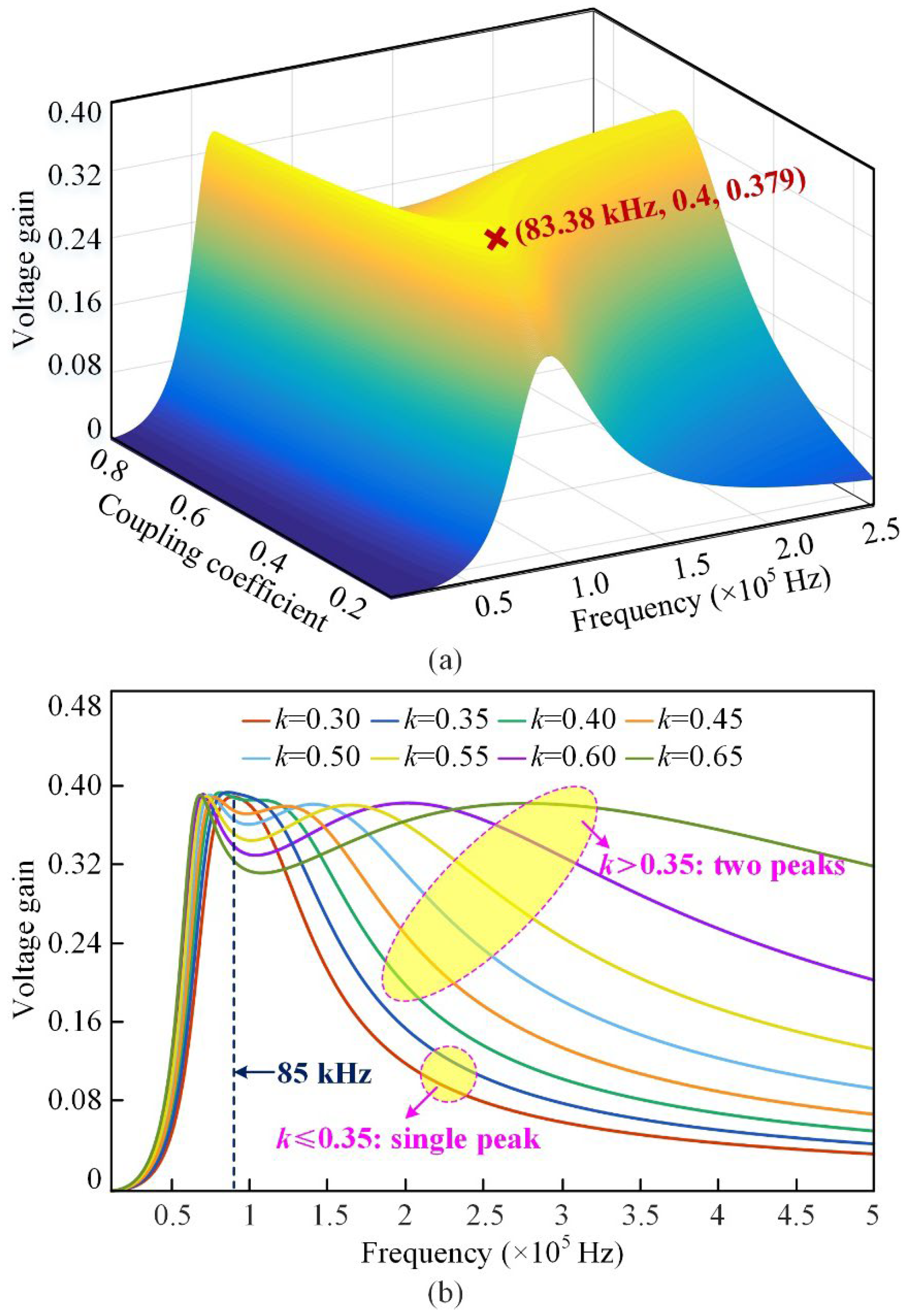
The output characteristics of UWCSs with small transmission distance remain unclear, especially in misaligned conditions. As explained in Section 2, the Tx and Rx coils are distanced at merely 20 mm, the thickness of epoxy resin layer on both sides together. Tight coupling is conducive to high output power yet misalignment-sensitive. In addition, resultant frequency splitting might cause the degradation of efficiency and power capacity and even unstable operation of UWCSs.
To summarize, problems 1–3 will not be discussed in the following since USV will either not be affected seriously by them, or these problems have been avoided effectively using the Rx limiter. As for problems 4–6, the former two will be elaborated on in Section 4.2 and Section 4.3, respectively. To better understand problem 6 for facilitating the coil design, a 3D finite element (FE) simulation is conducted in Maxwell 19.2.
Figure 5 gives the variation of coupling coefficient k between Tx and Rx coils versus 0-to-100 mm horizontal misalignment. For comparison, the cases corresponding to nominal transmission distance (1/4–1/2 characteristic length of a coil) are also investigated, except for the cases of 20 mm distance. Herein, one-Tx-one-Rx coil structure is exemplified for analysis. Two typical coil topologies are covered comprehensively, viz., circular coil and rectangular coil. Note that the volumes of different coils are the same. In addition, for rectangular coil, there are two moving directions of dmis, as shown at the bottom of Figure 5. In general, the k values for three different coils all decrease more sharply in 20 mm cases than in 80 mm cases. Higher sensitivity of magnetic coupling to the misalignment poses a challenge to the coil design. To our delight, the slope of the decline of k for coil 2 is not as steeper as coil 1 and coil 3. Even when the 100 mm misalignment reaches almost half its length, the drop of k compared to that of the aligned condition is barely 23.58%, which is acceptable in practice. Therefore, the following design will be based on this coil topology, and the directions of misalignment and coil length should be the same.
In addition to the deteriorated ability to combat the influence of misalignment, another challenge in the tight-coupling condition is frequency splitting. The phenomenon indicates that, the output power of an open-loop UWCS versus its operating frequency shows a multi-peak rather than single-peak pattern. For ease of analysis, the output power can be represented by voltage gain, which states
U O U I N V = R L j 2 π f k L 1 L 2 2 π f k 2 L 1 L 2 + Z 1 Z 2 + R L ,
where k is the coupling coefficient, and Z1 is the loop impedance of the Tx circuit. Putting the inductance of coil 2 in Figure 5 into Equation (6) and setting the parameters of resonance elements as per 85-kHz nominal frequency, Figure 6 depicts the voltage gain as a function of k and f. As can be seen from Figure 6a, when k equals 0.4, the maximum gain is associated with 83.38 kHz, which is deviated from the nominal frequency (85 kHz). The reason lies in that the UWCS has entered the tight-coupling region at this time. The critical coupling coefficient kc, the demarcation of loose-coupling and tight-coupling, can be calculated by taking the derivative of Equation (6) with respect to k, which states
k c R L R 1 1 Q 1 Q 2 ,
where Q1 and Q2 are the quality factor of Tx and Rx coils, respectively. Based on Equation (7), kc is calculated to be 0.35. Doubtlessly, the UWCS for USV will work in tight-coupling condition. As can be observed from Figure 6b, two-peak pattern is exhibited clearly. In this context, the frequency tracking strategy for the purpose of either maximum power or maximum efficiency might meet failure [31]. Hence, the operating frequency of UWCS should be fixed for a more stable operation.

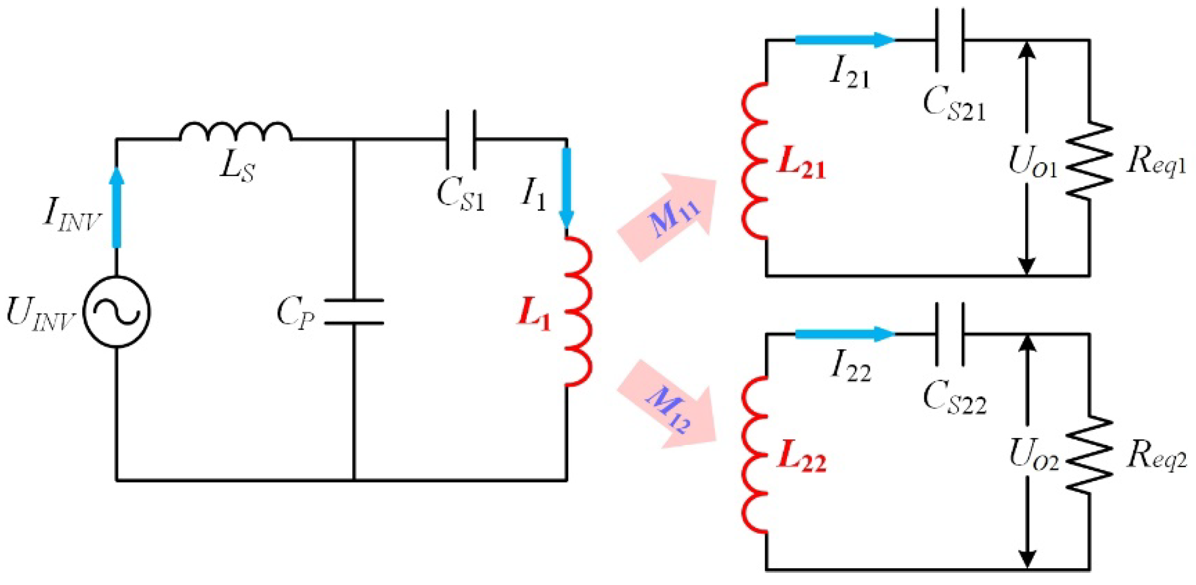
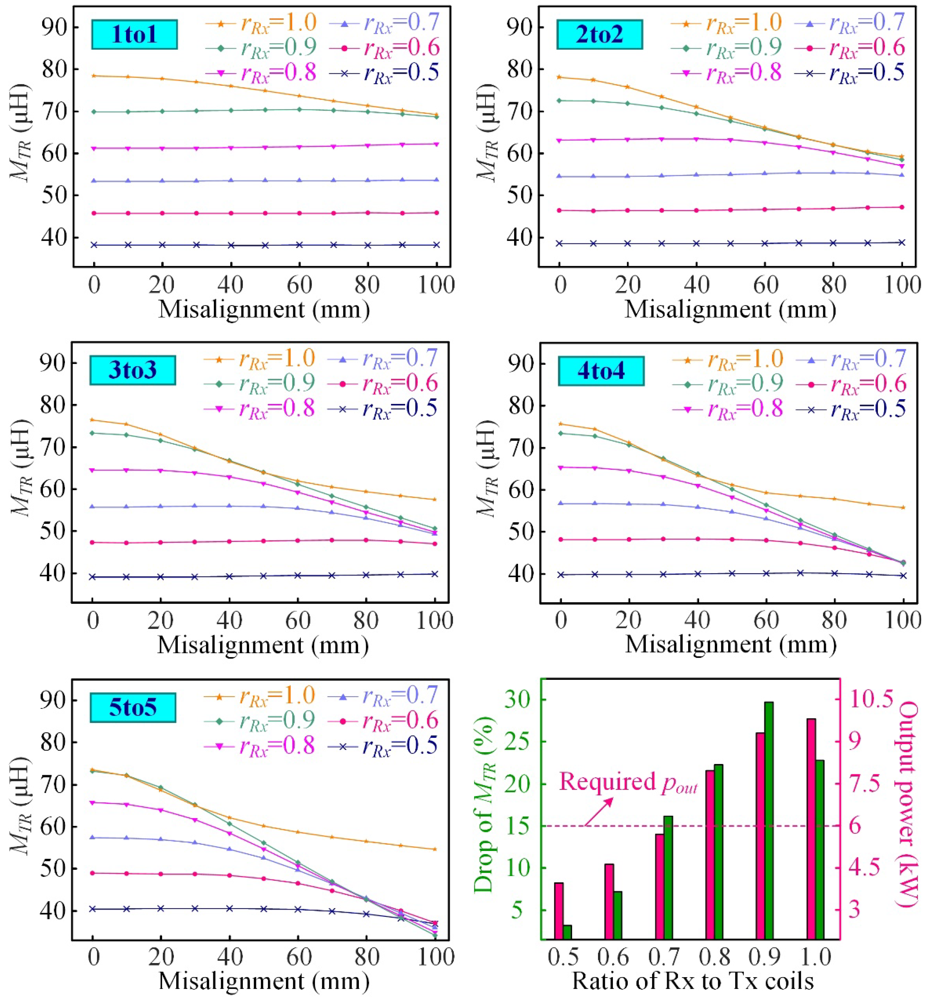
3.2. Comparison of Two Multi-Rx Coil Structures

According to the analysis of one-Tx-one-Rx structure, a rectangular coil with its length and horizontal misalignment sharing the same direction outperforms its peers. Moreover, in view of space utilization, viz., a coil’s occupancy divided by the capacity of USV, rectangular coils are also better than circular coils. To further enhance the misalignment tolerance, which is the main design purpose of UWCS, the multi-Rx coil structure is very promising. To be specific, two multi-Rx coil structures are alternative: one-Tx-multi-Rx, and multi-Tx-multi-Rx.
Figure 7 illustrates the size marks and material description of the multi-Rx coil structure. Two sets of Rx coils on USV are distanced at dRX2. Note that, for the ease of comparative analysis, only one of these two sets is used in the FE model since the coupling between them can be safely neglected. For each set, the relationship between the number of coils units and the distance of coil units states
l U S V = n l R x + n 1 d R x 1 ,
where n is the number of coil units of each set. Therefore, when n equals 1, 2, 3, 4, and 5, the values of dRX2 are 0 mm, 40 mm, 20 mm, 13.33 mm and 10 mm, respectively. The determination of dRX2 ensures that the cross-coupling of coil units of each set, which is usually regarded harmful, can be well controlled within 1% of the coupling between Tx and Rx coils or even smaller. The dmis is varied from 0 mm to 100 mm, which accords with the practice. Other key geometry parameters are also listed in Table 1. As for the Tx coils, if they have the same number of coil units as Rx coils, corresponding dTx1 are the same with dRx1, and corresponding lTx are the same with lRx.
The results of comparative analysis on two multi-Rx coil structures using the distribution characteristics of mutual inductance versus 0-to-100 mm horizontal misalignment are presented in Figure 8. In general, for the Rx coil units of the same number, the one-Tx-multi-Rx structure is apparently more competitive than the multi-Tx-multi-Rx structure. This is reflected in that, for the multi-Tx structure, the mutual inductance MTR between Tx and Rx coils is decreased by more than 20% from the aligned condition to the 100 mm maximum misalignment. At the same time, the counterpart of the one-Tx structure is stably smaller than 10%. Furthermore, according to the box chart, the median of MTR always appears in the lower part of the box, which signifies that the value of MTR has decreased significantly when dmis reaches 50 mm (the median of 0-to-100 mm misalignment). The reason lies in that, the ability of the multi-Tx structure to combat misalignment highly relies on the length of a single coil unit. The shorter the length, the smaller the misalignment tolerance. In contrast, this inherent problem can hardly influence the structure with a single long Tx coil at all.
Before jumping to selecting one of the two structures above, the misalignment tolerance of multi-Tx-multi-Rx structure should be further investigated by introducing a big-Tx-small-Rx scheme. That is to say, the reduction of Rx coil’s size is believed promising to maintain its high coupling level to the Tx coil in a larger charging area. To verify this point, the variation of MTR associated with different numbers of coil pairs and different ratios of the size of Rx coils to Tx coils (rRx) is depicted in Figure 9. In general, the smaller is rRx, the easier to strengthen the anti-misalignment ability in spite of the number of coil pairs, which partly demonstrates the effectiveness of this scheme. One exception is found when rRx is 0.9 and 1.0. This can be explained by taking a 5-Tx-5-Rx (5to5) structure as an example. Regarding the case of rRx = 1.0, when dmis increases, the coupling of a unit of Rx coils with its pair is decreased. Meanwhile, the coupling of this unit with the neighbor of its pair gradually increases. As for the case of rRx < 1.0, the coupling between originally paired coils is dominant unless dmis increases to a very high degree. Nevertheless, the pursuit of a very small rRx is also not acceptable. As revealed in the last subfigure of Figure 9 by taking a 3to3 structure as an example, the power capacity of an open-loop UWCS employing LCC-S compensation decreases with the shrink of Rx coils. Suppose the required output power is 6.0 kW, this requirement cannot be fulfilled when rRx is reduced to 0.7, not to mention the cases of rRx < 0.7, although the maximum attainable power reaches up to approximately 6.0 kW when rRx = 1.0.
To summarize, the big-Tx-small-Rx scheme can improve misalignment tolerance to some extent. However, the fundamental problem is that this scheme can hardly seek a compromise between misalignment tolerance and power capacity. Therefore, the one-Tx-multi-Rx structure is preferable in this work. The following discussion will be based on a one-Tx-four-Rx (1to4) structure.

4. Optimization of Coupling Coils Considering USV Endurance

4.1. Optimization Process

The flowchart of optimization process of the UWCS is represented in Figure 10. This process starts with the establishment of specifications of determined coil structure, assembly space on USV, etc. On this basis, two main optimization objectives are sought, namely, USV shape adaption and lightweight Rx assembly. For the former goal, the parameter to be determined is θ (degree of curvature of coils) and the criteria includes output power of the UWCS, effectiveness of Rx limiter, etc. As for the latter goal, different lightweight schemes are compared and analyzed, and the criteria includes output power of the UWCS, efficiency deterioration due to eddy-current loss, etc.

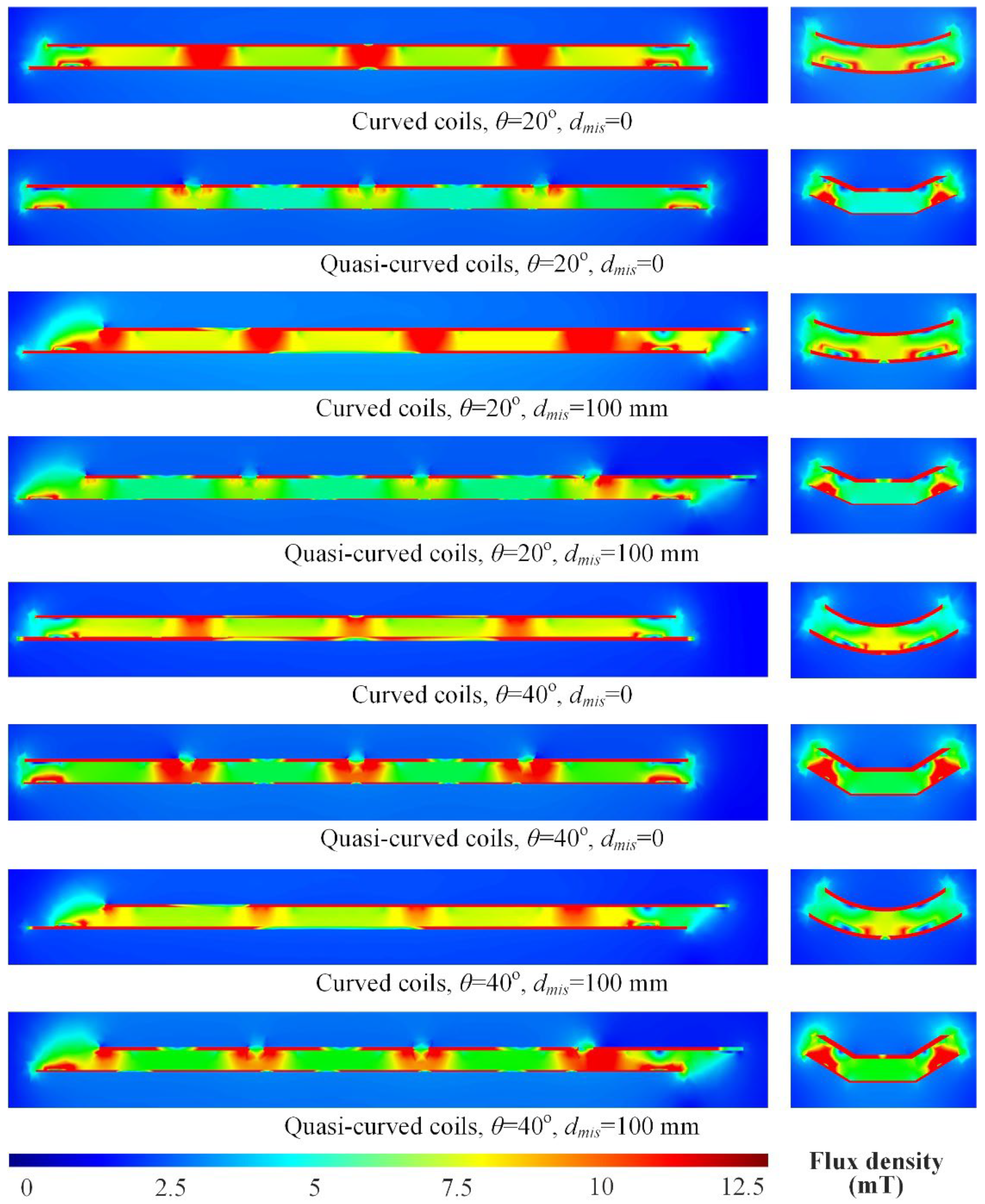
4.2. Curved Coils for USV-Shaped Adaption

Large misalignment tolerance is fundamental to the interoperability between the transmitter and receiver of the UWCS. On this basis, the performance of a charging system can be optimized by considering the practical requirements of USV sufficiently [32,33,34]. Among these requirements, one of the most important is USV’s endurance for the purpose of its continuity of operation, which urges that the equipped UWCS will not sacrifice the hydrodynamics. Therefore, instead of commonly used flat coils, two novel types of coils for USV-shaped adaption are devised and compared, i.e., curved and quasi-curved coils. Their geometries and size marks are depicted in the right part of Figure 11. For a fair comparison, their widths and chord heights are guaranteed the same. Moreover, the value of θ of both the Tx and Rx coils are kept the same, and the coil-to-coil distance is stably 20 mm. Either of these two coil topologies can ensure that the misalignment merely exists in the heading direction of USV. In other words, the USV is well aligned laterally.
The results of comparison of curved coils and quasi-curved coils of the same θ are given in the left part of Figure 11. Note that for quasi-curved coils, each θ corresponds to three different lb to conduct a more comprehensive comparison. It is revealed that this parameter is not very influential. Hence, herein, the comparison can be focused on the issue of coil topology. For a θ larger than 30°, curved topology is better without doubt due to relatively higher coupling. While when the θ is larger than 30°, the mutual inductance MTR associated with curved coils gradually exceeds quasi-curved coils. Nevertheless, it is notable that the ability of quasi-curved coils to combat misalignment is losing with the increase of θ, which is exhibited by a steeper drop of MTR (MD%). By contrast, this parameter is very stable for curved coils regardless of the variation of θ.
To better understand different degrees of coupling at the same coil-to-coil distance and θ, the field distribution is displayed in Figure 12, including the side view and front view. Considering the influence of lb on the electromagnetic performance is very limited, 90 mm lb is used as a representative for the three types of quasi-curved coils mentioned above. In general, for the 1 to 4 structure, the flux density reaches the maximum in the adjacent area of two coil units on the USV side due to the common flux path. When the θ equals 20°, the average flux density of curved coils is evidently higher than that of quasi-curved coils. Seen from the front view, although the flux is very concentrated on the side segments of quasi-curved coils, the enhancement of the overall flux density is not very significant. When the θ increases up to 40°, the flux gets even more concentrated, leading to the improvement of MTR. Although the coil-to-coil distance remains unchanged, the coupling of side segments on the Tx side and the flat segment on the USV side is enhanced effectively when the θ is increased to a certain level. However, this enhancement is received at the extra cost of deteriorated anti-misalignment ability. To summarize, curved coils preserve higher competitiveness for their stable misalignment tolerance and higher coupling level with a θ below 30°, which fulfills the practical requirement and therefore stands out.
On the basis of the selected coil topology, the value of θ should be further determined. As illustrated in Table 2, under various misalignment conditions, the mutual inductance shows a negative correlation with θ. Nevertheless, an Rx limiter with a θ approaching zero might be unable to restrict the lateral misalignment of USV. Therefore, a compromise should be reached between the level of magnetic coupling and the effectiveness of the Rx limiter. Eventually, 24° is selected.

4.3. Bar-Shaped Core for Lightweight Rx Assembly

Another key issue to enhance the endurance of USVs is the reduction of payload. Especially for the high-power charging system, the significance of lightweight design is more worthy of emphasis. As introduced in Figure 7, the magnetic coupler mainly consists of coils made of copper, a core made of ferrite, a shielding sheet made of aluminum, and an insulation layer made of epoxy resin. Among them, coils are fundamental. Reduced copper use will inevitably lead to the degradation of power capacity of UWCS. Moreover, the shielding sheet is also very important since the electronics of the USV must be protected properly from possible electromagnetic interference. Furthermore, the epoxy resin should be injected sufficiently since the electrical device for underwater use should be rated IP67. Therefore, the focus of lightweight design is concentrated on the ferrite core.
Figure 13 depicts 12 types of ferrite geometries of coupler assembled on USV. The reference design is a whole ferrite sheet, which is the base of our previous discussion. Compared with this one, the other 11 designs all realize the fundamental goal of reducing weight to varying extents. Nevertheless, the 4 designs in the last row of Figure 13 are deemed less feasible since the arrangement of ferrite bars poorly matches the field pattern of a rectangular coil, a kind of unpolarized coil [35]. In consequence, an improper low-reluctance path weakens the magnetic coupling. As for the remaining 7 designs in the first two rows, all ferrite bars in use correctly point to the center points of the coil. Moreover, the angle between any two adjacent bars is basically set to the same because there is no dominant direction of magnetic flux of an unpolarized coil.
In Figure 14, the evaluation of different lightweight designs is carried out. Six of them employ the technique of ferrite bars. The designs involving an air core (n = 0) and a ferrite sheet are used as references. Note that, for the cases of n = 4 and n = 8, there are separately two different arrangements of ferrite bars. Regarding the evaluation index, the mass of ferrite core and the ratio of reduced weight to Rx assembly directly reflect the effectiveness of the lightweight design. In addition, the mutual inductance between Tx and Rx coils is indispensable. The box chart of mutual inductance is obtained with misalignment ranging from 0–100 mm with a 10 mm step. What is more, the eddy-current loss indicates resultant efficiency deterioration arising from reduced ferrite. With a whole but heavy ferrite sheet, the eddy current in the shielding sheet can only be induced by the flux components penetrating the ferrite core. While for the lightweight designs, the shielding sheet is partly exposed to magnetic flux, facilitating the increase of eddy-current loss.
The results reflect that, first, the weight of coupler is decreased successfully. For n = 4, 8, 12, and 16, the mass of ferrite material is 2.76 kg, 5.52 kg, 8.28 kg and 11.04 kg, respectively. By contrast, the mass reaches up to 46.00 kg if a whole ferrite sheet is used. Accordingly, the ratio of reduced weight to that of Rx assembly is separately 53.49%, 50.28%, 47.07%, and 43.86%. This is calculated by knowing the weight of other components in advance, including the coils, shielding, and insulation. Secondly, although the mutual coupling between Tx and Rx coils becomes apparently lower, the maximum power capacity can still fulfill 6.0-kW requirement unless an air-core design is employed. This mainly owes to the tight-coupling condition in a 20 mm transmission distance. Thirdly, the extra eddy-current loss is acceptable. Taking n = 8 (type I) as an example, the loss of the shielding sheet is moderately increased by 20.16 W compared with that of a whole ferrite sheet according to FE analysis. This can be converted into a 0.336% efficiency drop for a 6.0-kW UWCS. From the perspective of thermal management, 20.16 W can also be easily handled. Based on the above, n = 8 (type I) is eventually selected.

5. Conclusions

In this paper, a 6.0 kW underwater WCS for USV, supported by an ancillary dock system, is analyzed, designed, and optimized in pursuit of a balanced power capacity, misalignment tolerance, and onboard weight. Firstly, six technical challenges of the UWCS design are summarized. In general, these challenges can either arise from underwater environment or USV practical requirements, such as hydrodynamics, endurance, and mission range. According to our analysis, under tight-coupling conditions, it is difficult to design a misalignment-resilient charging system. Secondly, targeted at alleviating the misalignment sensitivity, three different multi-Rx coil structures are investigated, including one-Tx-multi-Rx, multi-Tx-multi-Rx, and multi-Tx-multi-shrank-Rx. Regardless of the ratios of size of Rx coils to Tx coils, the one-Tx-multi-Rx always outperforms in view of power capacity and the drop of MTR. Thirdly, based on this coil structure, two types of coils aimed at USV shape adaption, viz., curved and quasi-curved coils, are devised and compared to sustain its endurance at a high level. Moreover, the θ, i.e., the chord height is optimized. Finally, the weight of receiver is effectively reduced using bar-shaped ferrite without sacrificing the power capacity of WCSs. A comparative analysis is carried out among 11 lightweight schemes. When eight ferrite bars are employed, the results indicate a merely 8.73% drop in coupling coefficient, with the misalignment ranging from 0 to 100 mm. Moreover, ferrite use is reduced by 40.48 kg compared to a ferrite sheet, which accounts for 50.28% weight of the receiver.

Author Contributions

Conceptualization, S.N. (Songyan Niu) and L.J.; validation, S.N. (Songyan Niu) and Q.Z.; formal analysis, Q.Z., H.C. and H.Y.; writing—original draft preparation, S.N. (Songyan Niu) and Q.Z.; and writing—review and editing, S.N. (Shuangxia Niu) and L.J. All authors have read and agreed to the published version of the manuscript.

Funding

This work was supported by the Science and Technology Innovation Committee of Shenzhen under Project 20200925154042003.

Conflicts of Interest

The authors declare no conflict of interest.

References

  1. Makar, A. Determination of the Minimum Safe Distance between a USV and a Hydro-Engineering Structure in a Restricted Water Region Sounding. Energies 2022, 15, 2441. [Google Scholar] [CrossRef]
  2. Specht, M.; Stateczny, A.; Specht, C.; Widźgowski, S.; Lewicka, O.; Wiśniewska, M. Concept of an Innovative Autonomous Unmanned System for Bathymetric Monitoring of Shallow Waterbodies (INNOBAT System). Energies 2021, 14, 5370. [Google Scholar] [CrossRef]
  3. Marchel, Ł.; Specht, C.; Specht, M. Assessment of the Steering Precision of a Hydrographic USV along Sounding Profiles Using a High-Precision GNSS RTK Receiver Supported Autopilot. Energies 2020, 13, 5637. [Google Scholar] [CrossRef]
  4. Painter, H.; Flynn, J. Current and Future Wet-Mate Connector Technology Developments for Scientific Seabed Observatory Applications. In Oceans 2006; IEEE: Piscataway, NJ, USA, 2006; pp. 1–6. [Google Scholar]
  5. Autonomous Survey Boat. 2019. Available online: https://www.oceanalpha.com/product-item/sl20 (accessed on 22 November 2022).
  6. Liu, C.; Hu, A.P.; Nair, N.K.C. Modelling and Analysis of a Capacitively Coupled Contactless Power Transfer System. IET Power Electron. 2011, 4, 808–815. [Google Scholar] [CrossRef]
  7. Urano, M.; Takahashi, A. Study on Underwater Wireless Power Transfer via Electric Coupling. In Proceedings of the 2016 IEEE International Meeting for Future of Electron Devices, Kansai (IMFEDK), Kyoto, Japan, 23–24 June 2016. [Google Scholar]
  8. Tamura, M.; Naka, Y.; Murai, K.; Nakata, T. Design of a Capacitive Wireless Power Transfer System for Operation in Fresh Water. IEEE Trans. Microw. Theory Tech. 2018, 66, 5873–5884. [Google Scholar] [CrossRef]
  9. Niu, S.; Xu, H.; Sun, Z.; Shao, Z.Y.; Jian, L. The state-of-the-arts of Wireless Electric Vehicle Charging via Magnetic Resonance: Principles, Standards and Core Technologies. Renew. Sustain. Energy Rev. 2019, 114, 109302. [Google Scholar] [CrossRef]
  10. Heeres, B.J.; Novotny, D.W.; Divan, D.M.; Lorenz, R.D. Contactless Underwater Power Delivery. In Proceedings of the 1994 Power Electronics Specialist Conference-PESC’94, Taipei, Taiwan, 20–25 June 1994. [Google Scholar]
  11. Granger, R.P.; Baer, C.M.; Gabriel, N.H.; Labosky, J.J.; Galford, T.C. Non-contact Wet Mateable Connectors for Power and Data Transmission. In 2013 OCEANS-San Diego; IEEE: Piscataway, NJ, USA, 2013. [Google Scholar]
  12. Zhang, K.; Zhang, X.; Zhu, Z.; Yan, Z.; Song, B.; Mi, C.C. A New Coil Structure to Reduce Eddy Current Loss of WPT Systems for Underwater Vehicles. IEEE Trans. Veh. Technol. 2019, 68, 245–253. [Google Scholar] [CrossRef]
  13. Yan, Z.; Zhang, Y.; Zhang, K.; Song, B.; Mi, C. Underwater Wireless Power Transfer System with a Curly Coil Structure for AUVs. IET Power Electron. 2019, 12, 2559–2565. [Google Scholar] [CrossRef] [Green Version]
  14. Cai, C.; Zhang, Y.; Wu, S.; Liu, J.; Zhang, Z.; Jiang, L. A Circumferential Coupled Dipole-Coil Magnetic Coupler for Autonomous Underwater Vehicles Wireless Charging Applications. IEEE Access 2020, 8, 65432–65442. [Google Scholar] [CrossRef]
  15. Zeng, Y.; Rong, C.; Lu, C.; Tao, X.; Liu, X.; Liu, R.; Liu, M. Misalignment Insensitive Wireless Power Transfer System Using a Hybrid Transmitter for Autonomous Underwater Vehicles. IEEE Trans. Ind. Appl. 2022, 58, 1298–1306. [Google Scholar] [CrossRef]
  16. Liu, Z.; Chen, Z.; Li, J. A Magnetic Tank System for Wireless Power Transfer. IEEE Microw. Wirel. Compon. Lett. 2017, 27, 443–445. [Google Scholar] [CrossRef]
  17. Kan, T.; Zhang, Y.; Yan, Z.; Mercier, P.P.; Mi, C.C. A Rotation-Resilient Wireless Charging System for Lightweight Autonomous Underwater Vehicles. IEEE Trans. Veh. Technol. 2018, 67, 6935–6942. [Google Scholar] [CrossRef]
  18. Mese, H.; Anilcan Budak, M. Efficiency Investigation of a 400W Resonant Inductive Wireless Power Transfer System for Underwater Unmanned Vehicles. In Proceedings of the 2020 IEEE Wireless Power Transfer Conference (WPTC), Seoul, Republic of Korea, 15–19 November 2020. [Google Scholar]
  19. Zhang, K.; Ma, Y.; Yan, Z.; Di, Z.; Song, B.; Hu, A.P. Eddy Current Loss and Detuning Effect of Seawater on Wireless Power Transfer. IEEE J. Emerg. Sel. Top. Power Electron. 2020, 8, 909–917. [Google Scholar] [CrossRef]
  20. Zhou, J.; Yao, P.; Chen, Y.; Guo, K.; Hu, S.; Sun, H. Design Considerations for a Self-Latching Coupling Structure of Inductive Power Transfer for Autonomous Underwater Vehicle. IEEE Trans. Ind. Appl. 2021, 57, 580–587. [Google Scholar] [CrossRef]
  21. Yan, Z.; Zhang, Y.; Kan, T.; Lu, F.; Zhang, K.; Song, B.; Mi, C.C. Frequency Optimization of a Loosely Coupled Underwater Wireless Power Transfer System Considering Eddy Current Loss. IEEE Trans. Ind. Electron. 2019, 66, 3468–3476. [Google Scholar] [CrossRef]
  22. Teeneti, C.R.; Truscott, T.T.; Beal, D.N.; Pantic, Z. Review of Wireless Charging Systems for Autonomous Underwater Vehicles. IEEE J. Ocean. Eng. 2021, 46, 68–87. [Google Scholar] [CrossRef]
  23. Niu, S.; Yu, H.; Niu, S.; Jian, L. Power Loss Analysis and Thermal Assessment on Wireless Electric Vehicle Charging Technology: The Over-temperature Risk of Ground Assembly Needs Attention. Appl. Energy 2020, 275, 115344. [Google Scholar] [CrossRef]
  24. Bi, Z.; Kan, T.; Mi, C.C.; Zhang, Y.; Zhao, Z.; Keoleian, G.A. A Review of Wireless Power Transfer for Electric Vehicles: Prospects to Enhance Sustainable Mobility. Appl. Energy 2016, 179, 413–425. [Google Scholar] [CrossRef] [Green Version]
  25. Jiang, C.; Chau, K.T.; Liu, W.; Liu, C.; Han, W.; Lam, W.H. An LCC-Compensated Multiple-Frequency Wireless Motor System. IEEE Trans. Ind. Inform. 2019, 15, 6023–6034. [Google Scholar] [CrossRef]
  26. Yoo, J.-S.; Gil, Y.-M.; Ahn, T.-Y. Steady-State Analysis and Optimal Design of an LLC Resonant Converter Considering Internal Loss Resistance. Energies 2022, 15, 8144. [Google Scholar] [CrossRef]
  27. Shafaei, R.; Perez, M.C.G.; Ordonez, M. Equivalence Relations of Resonant Tanks: A New Perspective for Selection and Design of Resonant Converters. IEEE Trans. Power Electron. 2020, 35, 9632–9649. [Google Scholar] [CrossRef]
  28. Yao, Y.; Wang, Y. A Novel Unsymmetrical Coupling Structure Based on Concentrated Magnetic Flux for High-Misalignment IPT Applications. IEEE Trans. Power Electron. 2018, 34, 3110–3123. [Google Scholar] [CrossRef]
  29. Xiang, L.; Sun, Y.; Tang, C.S.; Dai, X. Design of crossed DD coil for dynamic wireless charging of electric vehicles. In Proceedings of the 2017 IEEE PELS Workshop on Emerging Technologies: Wireless Power Transfer (WoW), Chongqing, China, 20–22 May 2017. [Google Scholar]
  30. Li, Z.; Li, D.; Lin, L.; Chen, Y. Design Considerations for Electromagnetic Couplers in Contactless Power Transmission Systems for Deep-sea Applications. J. Zhejiang Univ. Sci. C 2010, 11, 824–834. [Google Scholar] [CrossRef]
  31. Chen, H.; Niu, S.; Zhao, Z.; Jian, L. Wireless Power Transfer in Over-Coupled Region: Analysis on Frequency Splitting and Multi-Mode Frequency Selection Methods. In Proceedings of the 2021 IEEE 5th Conference on Energy Internet and Energy System Integration (EI2), Taiyuan, China, 22–24 October 2021. [Google Scholar]
  32. Wang, C.-N.; Yang, F.-C.; Nguyen, V.T.T.; Vo, N.T.M. CFD Analysis and Optimum Design for a Centrifugal Pump Using an Effectively Artificial Intelligent Algorithm. Micromachines 2022, 13, 1208. [Google Scholar] [CrossRef] [PubMed]
  33. Chen, Z.; Nguyen, V.T.T.; Tran, N.T. Optimum Design of the Volute Tongue Shape of a Low Specific Speed Centrifugal Pump. J. Electr. Electron. Syst. 2017, 6, 1–5. [Google Scholar] [CrossRef]
  34. Nguyen, T.; Vo, T. Centrifugal Pump Design: An Optimization. Eurasia Proc. Sci. Technol. Eng. Math. 2022, 17, 136–151. [Google Scholar] [CrossRef]
  35. Cheng, Y.; Shu, Y. A New Analytical Calculation of the Mutual Inductance of the Coaxial Spiral Rectangular Coils. IEEE Trans. Magn. 2014, 50, 1–6. [Google Scholar] [CrossRef]
Figure 1. Overview of UWCS. (a) Assembly of a transmitter in dock system and receiver in USV. (b) Exploded view of transmitter and receiver.
Energies 15 09529 g001
Figure 2. Working principle of Rx limiter.
Energies 15 09529 g002
Figure 3. Circuit configuration of an LCC-S compensated UWCS by parallel operation on USV side.
Energies 15 09529 g003
Figure 5. Comparison of coupling coefficient k versus horizontal misalignment with nominal and extremely small transmission distance, respectively.
Energies 15 09529 g005
Figure 6. (a) Voltage gain (UL/US) as a function of Tx-to-Rx coupling coefficient and operating frequency; (b) 2D curve of voltage gain in loosely coupled and over-coupled regions, respectively.
Energies 15 09529 g006
Figure 7. Size marks and material description of multi-Rx coil structure on USV.
Energies 15 09529 g007
Figure 8. Comparison of different coil structures using the distribution characteristics of mutual inductance versus 0-to-100 mm horizontal misalignment.
Energies 15 09529 g008
Figure 9. Variation of mutual inductance versus 0-to-100 mm horizontal misalignment with different numbers of coil pairs and different ratios of size of Rx coils to Tx coils.
Energies 15 09529 g009
Figure 10. A flowchart of optimization process.
Energies 15 09529 g010
Figure 11. Comparison of curved coils and quasi-curved coils of the same θ.
Energies 15 09529 g011
Figure 12. Field distribution of UWCS with different coil topologies, θ and misalignment conditions: side view (left) and front view (right).
Energies 15 09529 g012
Figure 13. Different ferrite geometries for Rx coils, including a reference design (a ferrite sheet) and 11 lightweight designs.
Energies 15 09529 g013
Figure 14. Performance of different lightweight designs in view of reduced weight of ferrite core, degree of magnetic coupling, and eddy current loss of shielding sheet.
Energies 15 09529 g014
Table 1. Geometry parameters of Tx and Rx coils of different coil structures.
ParameterValue 1ParameterValue 1ParameterValue 1
lUSV1000dRx12 (nRx = 1)0lRx3 (nRx = 1)960
wRx180dRx1 (nRx = 2)40lRx (nRx = 2)480
dRx2200dRx1 (nRx = 3)20lRx (nRx = 3)320
dTR20dRx1 (nRx = 4)13.33lRx (nRx = 4)240
dmis0–100dRx1 (nRx = 5)10lRx (nRx = 5)192
1 Unit: mm. 2 For Tx coils with the same number of coil units as Rx coils, corresponding dTx1 are the same as dRx1. 3 For Tx coils with the same number of coil units as Rx coils, corresponding lTx are the same as lRx.
Table 2. Average mutual inductance MTR sampled with 0-to-100 mm misalignment versus θ.
θ (deg.)MTR (μH)θ (deg.)MTR (μH)
065.762060.14
464.952458.38
863.912856.46
1262.923254.71
1661.573651.53
Publisher’s Note: MDPI stays neutral with regard to jurisdictional claims in published maps and institutional affiliations.

