1. Introduction
Digital convergence has been the basis for the emergence of several paradigms such as IoT, Industry 4.0, smart buildings, smart grids, smart cities, etc. [
1]. Through these paradigms, it is possible to carry out digital transformations in the most diverse systems in order to create digitally integrated structures, assets, or objects that can promote the evolution of pre-existing structures, known as legacy structures [
2]. This consists of the processes of technological convergence, which act in the updating of conventional systems to intelligent systems, allowing the implementation of new functionalities.
The processes of technological convergence or updating of legacy systems can occur abruptly or not [
3]. This will depend on the costs and time available for the implementation of solutions capable of promoting the desired new functionalities. Short-term solutions may involve larger investments that could make their implementations unfeasible and even lead to the discarding or replacement of pre-existing solutions, which could still contribute to their functionality or whose implementation costs are not fully amortized [
4]. Therefore, there are cases in which it is necessary to use processes that direct the technological transition with strategies that advocate the preservation of the legacy infrastructure for a gradual restructuring, for, otherwise, these processes would only be viable for absolutely new solutions.
In this sense, IoT solutions are one of the great allies in these convergence processes, as they allow the addition of new functionalities to common objects through the interconnection of these devices in a data network [
5]. In this way, it is possible to add communication resources, distributed computational processing, control, and remote sensing to legacy systems. In building facilities, the interconnection of pre-existing infrastructures through IoT solutions can result in the deployment of smart buildings, improving the safety, comfort, and efficiency of the present systems, in addition to delivering a better quality of life and experience to users. [
6,
7]. Likewise, IoT solutions can be applied in the implementation of smart grids so that electrical systems have maximum excellence in their operations [
8]. Thus, we can see the participation of the Internet of Things paradigm in the emergence of solutions capable of adding value in different scenarios through the interconnection of devices.
However, despite the great applicability of the IoT in the implementation of other paradigms, the lack of strategies that involve the integration of legacy building systems with remote control and monitoring systems in order to implement smart building systems is a problem. In this context, the retrofit strategy, used in convergence processes, can be applied to update old and technologically outdated devices, but that still necessary [
9]. Usually, retrofit techniques are used in building structures and legacy machinery in order to preserve them and add new features [
10,
11,
12,
13].
Even so, for the retrofit strategy to be implemented in a systemic way, through the integration of IoT elements with pre-existing infrastructures, it is necessary to use a reference model based on architectural definitions endowed with well-defined logical layers, protocols, and standardized interaction interfaces applied to the specifics of this particular context. It is important to mention some cases of implementation of the Industry 4.0 paradigm, which has been based on the use of standards or reference models, such as RAMI 4.0 [
14,
15]. Rocha et al. [
16] and Labeodan et al. [
17], for example, used the retrofit strategy to associate WSN in pre-existing building infrastructures. However, the systems presented did not use retrofit, from reference models, in order to standardize their implementations. Thus, it is inferred that another relevant problem for updating legacy systems is the absence of reference models that use retrofit techniques for the advancement of smart buildings.
Gomes et al. [
1] proposed the SmartLVGrid reference metamodel, applied to realize the smart grid convergence of legacy low-voltage power distribution systems. This model combines systems engineering strategies with the retrofit concept, allowing the transition from a legacy low-voltage plant to the smart grids paradigm. In addition, SmartLVGrid contains stacks of protocols that enable the interface of legacy infrastructures with compatible middleware (hardware and firmware) and that enable communication and the logical link (interoperability) between the elements located in the electrical grid with a supervision and control center. With this, we hypothesized that a strategy similar to that used in SmartLVGrid could be adapted to insert new control, monitoring, and communication resources in legacy devices located in building installations, instead of low-voltage consumer units or transformer stations. In this context, we did not find any literature studies that carried out investigations or practical implementations of strategies, including a reference model and use of retrofit, such as that of Gomes et al. [
1], however, it was focused on building environments for the implementation of smart buildings [
2,
16,
17,
18,
19,
20,
21,
22,
23,
24,
25,
26,
27,
28,
29,
30,
31,
32,
33,
34,
35,
36,
37,
38,
39,
40,
41,
42].
Therefore, in the present work, we adapt the SmartLVGrid metamodel and use retrofit techniques to develop a design and implementation strategy for IoT devices capable of converging legacy building systems into smart buildings. As a proof of concept, we used the adapted metamodel to insert network communication, monitoring, and digital control capabilities into a legacy building lighting circuit. For this, we developed embedded hardware platforms and, respectively, their firmware to implement the middleware and interoperability layers described in the aforementioned metamodel, but adapted to meet the circuits present in the lighting system in use. Throughout this work, the details of the developed platforms are described, at a physical and architectural level, with the necessary information so that it is possible to use the same methodology in the implementation of other systems. In this way, it is possible to implement new functionalities in the legacy building infrastructure, ensuring its maximum preservation.
The validation of the proposed system was carried out through the verification of the new functionalities inserted in the pre-existing circuit, according to the established middleware interfaces and interoperability specifications. In addition, to show that the adopted strategy can make the system more efficient, as recommended by the smart buildings paradigm, improvements in the lighting circuit in question in terms of energy performance will also be shown, that is, the improvements with respect to energy consumption, power factor, and total harmonic distortion (THD). As a result, the legacy lighting circuit now has the following attributes: measurement of electrical parameters in real time, control of the luminous flux, on/off control of the lighting system, transfer of energy phases from the luminaire to balance the circuit, and monitoring the on/off status and active power of each luminaire.
With the adaptation of the SmartLVGrid metamodel, we propose a new strategy for the convergence of smart buildings. Due to the exposed functionalities, it was possible to insert new resources, taking full advantage of the infrastructure and elements present in the building installation. Thus, the proposed strategy allows scalability through the interoperability layer, which integrates new devices in groups or clusters to the system, from distributed processing, as each legacy lighting circuit is now independently monitored/controlled. A highlight of the proposal is the systemic method used to integrate IoT embedded solutions with passive legacy devices. Therefore, we list the contributions generated in this article below:
- 1.
Implementation of a smart building system through the adaptation of the SmartLVGrid metamodel and the retrofit strategy in a systemic way to insert electronic control and monitoring resources in legacy building infrastructures, preserving them as much as possible.
- 2.
Development, implementation, and design of hardware devices and their respective firmware to enable the retrofit of building lighting circuits, based on the premises of the SmartLVGrid reference model.
- 3.
Presentation of resources for intelligent control and monitoring in lighting systems, such as phase transfer, luminous flux control, and request for power parameters and on/off operating status of the lamps.
- 4.
Improvements in the energy performance of the building’s lighting system after using the proposed model for the implementation of smart buildings. The improvements obtained are presented in terms of power factor, total harmonic distortion (THD), and energy consumption.
To present the proposal of this work, the article is divided into the following sections.
Section 2 shows the related works and the difference of this work in relation to the literature.
Section 3 presents theoretical concepts used throughout later sections.
Section 4 shows the proposed system, including the architecture of the modules developed for retrofitting lighting and energy metering systems.
Section 5 presents the material used and the implementation of the proposed method.
Section 6 and
Section 7 present the results and conclusions obtained with this work, respectively.
2. Related Work
The integration of legacy infrastructures into smart building ecosystems is a constant theme cited in the literature. In [
18,
19,
20], the authors discuss processes for automating legacy infrastructure using retrofit techniques. Ibaseta et al. [
21] presented an architectural model for intelligent retrofit that enabled the interoperability of sensor elements through the World Wide Web Consortium (W3C) specifications, together with the building energy management system (BEMS) method. However, most available methods were exclusively designed to meet a pre-established number of cases and systems, making scalability, distributed processing, and interoperability with other applications difficult. Furthermore, the architectural models presented did not expose, in general, a standardization of the retrofit technique for a greater number of legacy devices, of the same nature or not.
As an alternative to standardize methods capable of enabling convergence processes based on IoT, the literature exposes solutions based on middleware and interoperability models that contribute to the interface and interaction of heterogeneous systems. In [
22], the author presented a communication network infrastructure to allow the integration of legacy electrical equipment into smart grids using wireless sensor networks. The same author, in [
36], proposed a middleware to monitor electrical parameters in wireless sensor networks (WSNs), enabling smart grid convergence through the retrofit of legacy meters. Similarly, the authors of [
23] developed devices that communicate in a multi-protocol network in order to monitor the electrical parameters of transformers, enabling the implementation of a smart grid. Roalter et al. [
29] exposed a middleware for smart office environments. An interoperability layer was proposed in [
2] to allow the migration of industrial legacy systems with minimal changes to these structures. Also focusing on the standardization of the methods inserted in this context, Marinakis and Doukas [
24] presented a semantic structure to enable the intelligent management and operation of energy in smart buildings.
The aforementioned works did not address the integration of middlewares with interoperability layers or with the legacy layer through primitives or methodologies that describe a generic interface for communication with any legacy devices. The computational resources described in the platforms used were also not based on predefined models. Thus, even with the standardization of the insertion of these devices in the network, a generic model for other cases and systems should have been adopted. In this way, it would be possible to implement the virtualization of the legacy asset and its interface with the retrofit element, in addition to guaranteeing the digital convergence of any legacy element.
In this context, metamodels can be used in the analysis, construction, and development of models capable of integrating legacy systems with middleware interfaces and interoperability layers [
25]. Therefore, these metamodels are capable of making changes to pre-existing infrastructures, as evidenced in [
26,
27]. Thus, we seek a metamodel whose premise is based on the technological convergence of legacy systems. In this case, Cicirelli et al. [
28] presented a metamodel to model attributes and relationships offered for device interactions in smart environments. In [
4], Gomes et al. introduced a meta-system that had retrofit strategies to insert smart grid functionality into legacy power distribution systems. Then, in [
1], the evolution of this architecture in the SmartLVGrid metamodel was observed. This model integrates the aforementioned middleware structure with an interoperability layer, which describes hierarchical aspects and the use of protocols and semantics for information exchange. In general aspects, this structure could be used to update legacy devices located in building installations, enabling the implementation of smart environments.
The literature exposes many works associated with smart building convergence processes [
29,
30,
31,
32,
33,
34]. Associated with the target infrastructure of this work, other works presented solutions for lighting control and energy metering in the building environment [
22,
35,
36,
37,
38,
39,
40,
41,
42]. However, we did not find works that describe metamodels capable of providing the insertion of automation, electronic control, distributed processing, and communication resources in building environments, through retrofit techniques or using metamodels for this purpose. As one of the attributes of the lighting system retrofit, a method to carry out the phase transfer was proposed, already mentioned in other works in the literature [
43,
44,
45]. However, in this article, in an unprecedented way, this method was implemented as one of the features of the hardware module specially developed for lighting control in the context of smart buildings. As a way of synthesizing the approach taken in this section,
Table 1 illustrates a comparison of the contributions proposed in this work when compared with the main works found in the literature.
As shown in
Table 1, the works found in the literature do not have all the contributions presented in this work. Few works address the use of metamodels and retrofit techniques to provide technological transitions. Furthermore, most of the work focuses on solutions for specific problems, without adopting architectural models as a basis for scalability.
On the other hand, the present work, compared to those mentioned above, is distinguished by presenting a method dedicated to the smart building convergence of legacy building infrastructures, from the retrofit of the lighting system of these installations, as long as they consist of common LED luminaires, regardless of brand, model, or manufacturer. The method uses the SmartLVGrid metamodel as a reference in the convergence process, implementing the interface devices (middleware layer) between the model’s logical layer (interoperability) and the legacy infrastructure (physical layer). Thus, this approach fills a gap observed in the state of the art (and technique) of systems applied to smart buildings.
3. Concepts
This section supports the concepts used in the elaboration of this work, which include aspects of smart buildings and the SmartLVGrid metamodel.
3.1. Smart Buildings
Smart building is a paradigm for controlling and monitoring electronic devices located in a building installation, interconnected through a complex data network [
46,
47]. The IoT, in turn, is a great ally of this paradigm. In this way, sensors and actuators can be used in the automation of a building, through the Internet or through specific communication protocols that enable safety in their operations, whenever possible. In addition, this process can be performed using real-time hardware and software platforms, enabling more accurate decision-making or even automatic control of these systems [
48].
Smart buildings can have infrastructure to enable comfort and better use of energy and natural resources, in order to reduce costs and enhance the construct [
49]. In this meaning, the scope of a smart building can encompass heating, ventilation, and air-conditioning (HVAC) systems, lighting systems, hydraulic systems, and building electrical systems, among others.
3.2. SmartLVGrid
The SmartLVGrid metamodel is a descriptive model of a strategy, with its respective protocols, applied to technological convergence in smart grids in the low voltage distribution system through the adaptation of the legacy circuits that compose it. The retrofit method and its respective implementation strategy are integral parts of this model [
1].
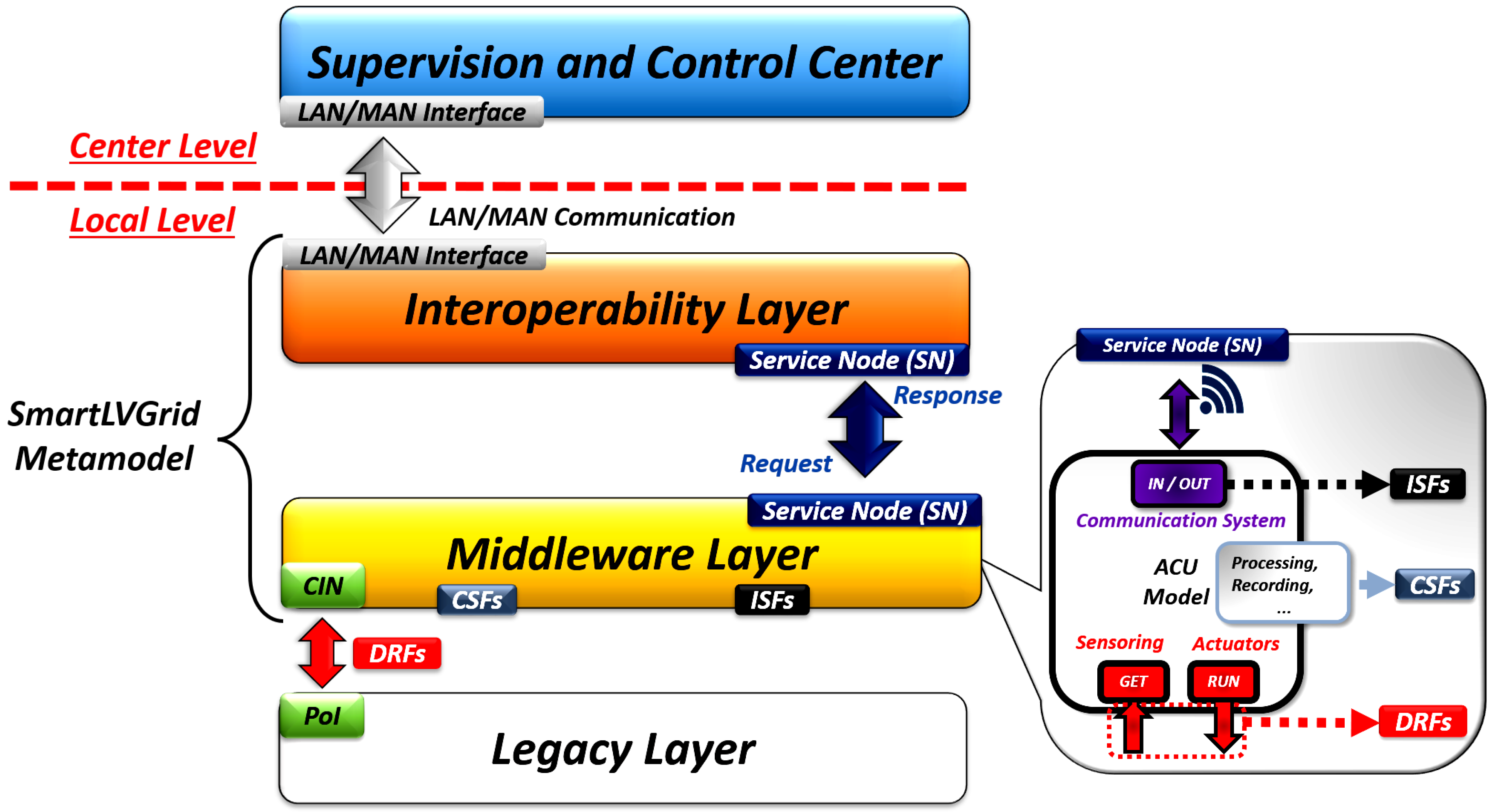
By analyzing
Figure 1, it is possible to observe that the metamodel is structured at the local and central levels, respectively, close to the legacy structure and close to the supervisory monitoring center of the system. If there may be a geographic or local separation between the local and central levels, the metamodel foresees the use of metropolitan area or local area network interfaces to allow connection and communication between these levels.
At the local level, the retrofit modules are installed at points of interface (PoI), located under the legacy structure, where it is possible to carry out the connection between the upper layers at the local level, enabling the exchange of messages and other interactions. In the middleware layer, the coupling and interaction node (CIN) is connected to the point of interface of the legacy layer in order to perform microprocesses classified as domain retrofitting functions (DRFs). In addition to DRFs, there are computational support functions (CSFs) and interdomain support functions (ISFs), whose objectives are, respectively, to provide access interfaces to all computational services (eg data storage and processing) that the middleware can offer and enable network communication through available protocols. DRFs, CSFs, and ISFs are classified in this model as operational primitives (OPs) and can be implemented according to needs and available resources.
Typically, DRFs, CSFs, and ISFs are based on processes performed manually by a field operator. However, with the adaptation implemented through CIN, they can be performed by automatic control. Analogous to CIN, service nodes (SN) are logical units that interact between the interoperability and middleware layers.
Therefore, the main purpose of SmartLVGrid is to establish a model for the conversion of a passive system into a system with communication and automation resources, which allows remote control and supervision and, in some cases, the local and autonomous operation of the structure legacy.
3.2.1. Middleware Layer
The middleware layer operates at the lowest level of the metamodel, interfacing with the legacy infrastructure through the PoIs (points of interface) that implement the DRFs (domain retrofitting functions). Thus, the hardware used to implement the DRFs, loaded with firmware, sensors, and actuators, physically implements the model. As illustrated in
Figure 1, the middleware layer is also called the automation and communication unit (ACU), whose functionality will depend on the DRFs to be executed and the type of legacy structure with which it interacts.
Essentially, the ACU consists of three ports: “In/Out”, “Get”, and “Run”. The “Get” port has the function of collecting data from pre-established variables for measurements and detection of possible violations of the operating limits from the retrofit device. The “Run” port, in turn, has functionalities for acting and controlling the interface points (PoI) with the legacy layer. The communication methods and processes performed by the ACU are performed through the “In/Out” port of the model. ACU ports relate to operational primitive classes as follows: DRFs are performed by the “Get” and “Run” ports; CSFs run within the framework of the ACU, such as processing and data storage capacity, for example, and ISFs are run through the “In/Out” ports.
3.2.2. Interoperability Layer
The interoperability layer defines the rules, criteria, and infrastructure necessary to make the necessary connections and organize the ACUs in a hierarchical network, enabling access to executed services and interactions between objects. Furthermore, this layer specifies a distributed computing system to support the upper layers, where the supervisory, control, business intelligence, and analytics interfaces are provided. Unlike the software defined networking (SDN) paradigm applied to the smart grids paradigm Abujubbeh et al. [
50], the SmartLVGrid interoperability layer enables hierarchical organization and communication dealings at a local level. Thus, it is possible to manage the system remotely and distributed.
The model states that the system must have a coordinator element, which monitors and supervises all other elements, called operators, that will execute the operational primitives. Although there is a hierarchical network in the system, operators can act with their services independently, storing data temporarily and later communicating with the coordinator to send the data. In addition, they can carry out control operations as needed for larger hierarchies.
Finally, the interoperability layer is also used to associate nomenclatures with ACUs, in order to make the interface and communication more intuitive, both for the coordinators and for the operators.
4. System Architecture
To achieve smart building convergence, we implemented and adapted the middleware and interoperability layer of the SmartLVGrid metamodel, previously intended for legacy low-voltage circuits, with the aim of inserting retrofit platforms for automation and control in the legacy lighting system in an environment building. Thus, the interfaces previously planned to be consumer units or distribution transformer stations will be proposed for electronic circuits and legacy devices located in the building installation.
Figure 2 illustrates a previous model of the implementation method of the developed retrofit platforms, which represent the partial structure of a smart building.
As illustrated in
Figure 2, we performed the retrofit by replacing the drivers of conventional luminaires (1) by smart LED drivers (2) that we developed. The smart LED drivers developed have a system-on-a-chip (SoC) to provide control, monitoring, and communication resources. Furthermore, they are based on buck PFC (power factor controller) converters, which ensure higher power factor and better efficiency [
51], justifying the replacement of the old control device.
A smart power meter (3) was coupled to the lighting circuit, which acted as coordinator to manage the new LED drivers and collect the circuit’s electrical parameters. The smart LED drivers and smart power meter were named in the interoperability layer, respectively, as ACU-LUMs, correlated to “luminaires”, and ACU-SB, correlated to “smart buildings”.
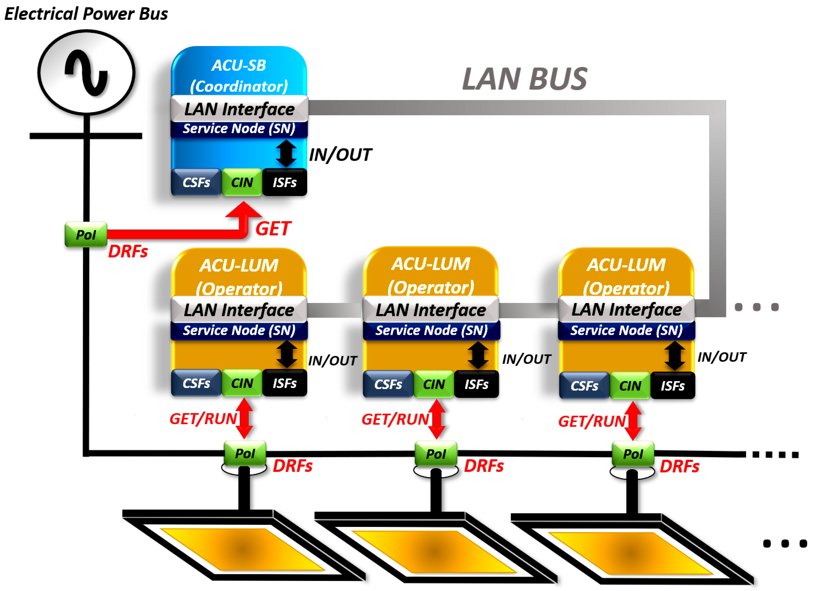
The adaptations made to the original architecture of the SmartLVGrid metamodel, based on the devices presented above, are illustrated in the diagram in
Figure 3. This diagram depicts an architecture similar to the work of Gomes et al. [
1]; however, here it has been adapted for new device profiles, such as ACU-LUM and ACU-SB. It is observed that the standard of local networks (LAN) was chosen for the interconnection of the devices, in view of the proximity of these elements in the environment in use. Another important factor is the relationship between the ACUs and their respective legacy domains, as the SmartLVGrid metamodel only describes interfaces and operational primitives for loads and devices located in low-voltage electrical distribution systems. In this work, we propose the realization of these interfaces in electronic devices of a lighting circuit in order to execute the necessary DRFs, CSFs, and ISFs. Furthermore, it is possible to notice in the figure the relations of the service nodes (SN) and the “Get”, “Run”, and “In/Out” ports with the legacy devices of the building lighting circuit and with the data network. The architecture of the proposed system, as established by the interoperability layer, is also illustrated, where the ACU-SB is called coordinator, and the ACU-LUM, operator.
Figure 4 illustrates the individual architectures of ACU-LUM (a) and ACU-SB (b), with their respective operational primitives and interfaces with legacy systems and with the data network.
4.1. ACU-LUM Architecture
In the pre-existing legacy structure, there were luminaires consisting of arrays of LEDs in series. Therefore, as a proposal for one of its DRFs, this ACU had to be able to regulate the current of the LEDs, aiming at controlling the luminous flux. In order to remove from the human operator some manual operations in the lighting system, the automatic on/off control was developed as DRF, as well as the availability of the luminaire’s operating status and the individual power consumption of each luminaire on the network. In addition, we also proposed the functionality of switching between supply phases for possible system balancing. Structurally, the port “Get” acted in the detection of the luminaire’s operation and in the collection of electrical parameters, while the “Run” port acted on the switching between phases, on/off control, and on the luminous flux control. To integrate with this convergence model, communication elements were inserted in this ACU to enable its integration with the interoperability layer, through the “In/Out” port.
ACU-LUM CSFs were implemented to manage connection services and for data storage. This made it possible to store the network parameters to which the ACU connected. The ISFs, in turn, played a role in the execution of the communication process so that it was possible to send commands or requests to the ACU-LUM through the network interface of the interoperability layer.
4.2. ACU-SB Architecture
The ACU-SB was responsible for collecting the electrical parameters of the lighting circuit. Structurally, this functionality was performed through the “Get” port of this ACU, as well as communicating through the network interface through the “In/Out” port. The CSFs and ISFs were implemented similar to those of the ACU-LUM. However, as an addition to its CSFs, this ACU acted as a concentrator of monitored data from each ACU-LUM connected to the lighting circuit. It also had more resources for communication, allowing connections with other devices or those that needed to gain access to the cluster to which this ACU was inserted. In addition, the ACU-SB has conditioning and protection features against possible overcurrent and overvoltage surges, which allowed this device to function properly in such events.
5. Materials and Methods
For the physical implementation of the ACUs, it was necessary to develop hardware prototypes, with their respective firmwares, compatible with what is proposed for the retrofit model used. Therefore, the concepts and strategies adopted to implement these elements are discussed throughout this section.
5.1. Implementation of the LAN Interface and the Interoperability Layer for the ACUs
The SmartLVGrid metamodel does not establish specific protocols to be used because, as it is a non-abrupt convergence process, the user can adapt the communication system to what is most viable in terms of infrastructure and available resources. In [
23], the authors implemented a communication network based on the IEEE 802.15.4 standard. Although this communication pattern is more viable for WSN, given the low consumption and low data rate [
52], the retrofit strategy requires maximum use of the pre-existing infrastructure. Therefore, in this work, we chose to use the MQTT communication protocol, taking advantage of the legacy Wi-Fi network infrastructure available in the building.
MQTT is a protocol characterized by its lightness in the network communication process and is optimized for use under the TCP/IP stack. For the sensors and actuators that use it, this implies less energy consumption and the possibility of transferring data through a local network or the internet. MQTT requires a server known as a broker, where clients can subscribe to topics, to receive data over the network, or publish data in specific topics [
53]. To implement this work, a local open source MQTT broker, known as Mosquitto, was adopted. Mosquitto supports multiple ports for communication via MQTT. However, in this work, the standard TCP port 1883 was used.
The broker was available in the ACU-SB, having the role of concentrating element of the system. The firmware corresponding to the ACU-LUM was used to enable connection to the broker through the IP address from the machine where this server was running and also through TCP port 1883. Thus, by establishing the connection with the local Wi-Fi network and with the MQTT broker, service nodes (SNs) were implemented.
So that the ACUs could interact in the interoperability layer through the LAN interface, data packets that encapsulated commands, requests, and responses in JSON format were used. It is noteworthy that the response messages were generated only from the requests sent. Other methods for data serialization could also be used, however, the JSON pattern proved to be more viable in the implementation of the system. In this way, these data packets were transmitted so that the DRFs could be executed via MQTT.
The security of this protocol depends, in addition to MQTT security elements, on a specific field in the JSON containing the identification of the ACU operator and on an access key to execute each DRF. Only the ACU coordinator was enabled to send commands directly to operators located in the same cluster. In this way, the end user could obtain this information by communicating from a supervisory center with the coordinator or by directly accessing the coordinator’s hardware. Topics for publication and subscription via MQTT were defined from the address of each ACU in the network.
As an example,
Figure 5 presents command (1), request (2), and response (3) packets sent in JSON format. In these packages, it is possible to visualize the destination address of the illustrated ACU-LUM, which in this case is the “ACU-LUM 01”. In addition, it is observed in (1) the key command to activate the luminaire and, in (2), the request key to obtain its operating status. Each DRF has a preset value to be sent in the key command, which enables its execution. In (1), the value ”00” was used to trigger the activation of the luminaire through that command. Thus, the ISFs were responsible, through the SNs and the available LAN interface, to ensure the interoperability between the operator device and the coordinator.
In response to the request, in (3), the ACU operator responded to the message by addressing it to the ACU coordinator. The response message includes the request field for the operating status plus the response obtained through the proposed hardware. As illustrated, the ACU-LUM responded to the status with the Boolean value “True”, indicating that the fixture is on.
5.2. ACU-LUM Implementation
The implementation of this device occurred through the junction of an SoC, containing a microcontroller and communication peripherals, with a switched converter used to control the luminaire. In this case, we chose to use the buck PFC converter because of its low implementation cost and because it enables the improvement of power factor and total harmonic distortion (THD) of the load when connected to the power grid.
The system power was obtained by the four-wire electrical power distribution system, in star, 220/127 V at 60 Hz. In order to prevent the disturbances produced by the switching of devices from harming the power quality of this network, electromagnetic interference (EMI) filters were implemented in the ACU-LUM.
The luminous flux control was carried out through commands passed through a communication network to the control circuit of the buck converter. For this, the SoC ESP32 and its internal digital-to-analog converter (DAC) were used, together with the integrated circuit (IC) FL7701. This integrated circuit enabled the implementation of the LED driver based on the buck PFC topology. The voltage coming from the ESP32 DAC, applied to the FL7701, allowed the control of the current supplied to the luminaire’s LEDs.
In the design of the converter, the respective guidelines of IC FL7701 provided by its manufacturer were used. The elements that make up this converter were calculated to meet 6 W LED luminaires, where the original LED driver supplies the LED set with about 300 mA.
Table 2 presents the components used together with IC FL7701 to compose the ACU-LUM.
The SoC ESP32 was used in this device to carry out the functionalities proposed in the architecture of this device, such as changing the lighting supply phase, controlling the luminous flux of lamps, and monitoring and controlling the on/off status of the loads. To monitor the active power and operating status of the lighting fixtures, this module captures information from the shunt resistor used in the converter and makes it available in a wireless communication network, using the MQTT protocol in the building’s Wi-Fi network. In this way, ISFs are carried out in the communication process and DRFs associated with luminous flux control, luminaire functioning detection, and measurement of power consumption. CSFs were implemented through the embedded firmware used as described above.
We developed and coupled, at the input of each ACU-LUM, a module for selecting the phase of energizing the circuits. This phase selection module is composed of three TRIACs of the BTA24 model and their respective optocouplers, model MOC3063 with ZVS technology, to perform the phase switching of the circuits at the moment of zero voltage crossing. Thus, the TRIAC will not activate until a zero crossing of the source voltage occurs and the load current starts to conduct after this time [
45]. Through the phase selection module and a switching algorithm inserted in the firmware, the microcontroller can switch between phases and carry out on/off control of the luminaire, thus executing the two remaining DRFs for this ACU. Finally, using Altium software, we developed the ACU-LUM schematic and layout for testing and validation. The 3D layout of the board (a) and its respective prototype (b) are illustrated in
Figure 6.
5.3. ACU-SB Implementation
The development of the ACU-SB was based on a hardware device capable of performing all computational processing to manage the functioning of the luminaires and measure the electrical parameters referring to the phases where each ACU-LUM was connected. The 3D layout of the board (a) and the respective prototype of this ACU (b) are illustrated in
Figure 7. The computational power of the ACU-SB is superior to the ACU-LUM, as will be specified later. This ACU has the system in module (SoM) Colibri iMX6 ULL from the manufacturer Toradex, with Wi-Fi communication capabilities and the Linux operating system known as Ångström, provided by the manufacturer with file system and all kernel drivers.
The SoM iMX6 ULL will establish a serial connection with the IC ADE9000 through a digital galvanic isolator. The IC ADE9000 is capable of collecting and transforming into digital values all the electrical parameters of the three-phase system to which each ACU-LUM will be connected [
54]. In addition, we have included circuits for voltage and current signal conditioning and surge protection devices in the ACU-SB, such as GDTs (gas discharge tubes), PTC (positive temperature coefficient), and NTC (negative temperature coefficient) fuses. We also perform the necessary procedures for calibrating the IC ADE9000, by adjusting its registers and using the precision source PTS 400.3, as specified in the IC ADE9000 technical reference manual [
55]. Calibration was performed predicting a maximum error of 1% in the measurement values. The ACU-SB also envisions a power backup system, using a 3.7 V Li-Po (lithium polymer) battery to keep the processing unit functional at all times.
5.4. Installing ACU-LUM and ACU-SB
To use the ACU-LUM and ACU-SB for retrofit according to the SmartLVGrid platform, it was necessary to identify the interface points (PoIs) of the legacy systems and the available communication systems, through which the service nodes (SNs) were implemented.
The ACU-LUM had its output connected to the luminaire input and its input connected to the three-phase power supply with a neutral, coming from the electrical panel lighting circuit. This adaptation was carried out in order to enable the phase change of the ACU-LUM power supply, as this is one of its DRFs.
Figure 8 presents this implementation.
The ACU-SB was positioned at the three-phase power supply circuit output, where the interface points with the luminaires were located. It was necessary to adapt cables and connections for their installation in the distribution board. In this way, the current transformers and the voltage connectors were placed directly at the output of the three-phase circuit. These connections are illustrated in
Figure 9.
Through the local Wi-Fi network in the building, service nodes (SNs) were implemented for the two projected ACUs. The modules of the ACU-LUM type were configured in star topology, having the ACU-SB itself as a concentrator. With this, the interoperability layer was allowed to perform the interconnection between the ACU-LUM and ACU-SB service nodes. In this context, other retrofit devices may come to be part of this architecture.
6. Results
With the implementation of ACU-LUM and ACU-SB and the insertion of these devices in the legacy system, as proposed in the system architecture, a test scenario was established to obtain the results and validate the new functionalities of the pre-existing structure. In this scenario, commands, requests, and responses were made between an ACU-LUM and an ACU-SB in accordance with the premises and specifications of the interoperability layer. Thus, it was possible to test the operational primitives assigned to each ACU and evaluate the improvements obtained with the proposed system.
First, it was necessary to register the ACUs on the local Wi-Fi network to allow access to the MQTT broker. In turn, this action exemplifies the implementation of SNs between the middleware layer (ACUs) and the interoperability layer. Once powered on, the ACU-SB initializes the MQTT broker to allow the connection of the other retrofit modules. Thus, communication between the devices in the test environment was established. In addition, it was necessary to establish the messages in JSON format to validate the new features of the system. Based on the identification of the ACUs used, the topic MQTT used to send and receive these messages was also defined.
Table 3 shows the DFRs to be validated, the message method (command, request, or response), the identifications of the ACUs in the used network (ACU ID), the MQTT topics used, and the respective messages, containing the access keys and the values to be passed in commands or responses. The identifications of each message (ID) and the size in bytes of each message in JSON format were also inserted. The ”(
value)” field in message 9 refers to the power value predicted by the ACU-LUM, considering 4 decimal places. Then, the size in bytes of this message is kept as 26 B.
Throughout this section, the results obtained with the implementation of the proposed system will be presented. Initially, the energy performance of the ACU-LUM was evaluated in relation to the legacy driver of the luminaires. Then, to validate the results regarding the proposed system, a sequence of procedures was followed to verify the new functionalities based on the established operational primitives:
- 1.
Validation of implemented computational support functions (CSFs).
- 2.
The verification of ISFs, through the communication protocol implemented in this system.
- 3.
The execution of the retrofitting functions (DRFs) performed by each ACU under their respective legacy structures (domain).
6.1. Evaluation of the ACU-LUM’s Energy Performance in Operation
The retrofit strategy made it possible, in addition to the resources already mentioned, to reduce energy consumption and improve energy quality parameters in the lighting circuit. This was verified through measurements taken while the legacy driver or the ACU-LUM powered the luminaire. The parameters measured were energy and power consumed, power factor, and total harmonic distortion (THD). We emphasize that these measurements were made using the Fluke 434-II energy analyzer. The legacy LED driver, when connected to the luminaire, had a consumed power of 6.1 W, a power factor of 0.47, and a THD of 127%. On the other hand,
Table 4 shows how much the consumed power can be reduced in the dimming process when connecting ACU-LUM to the luminaire. In addition, the table presents the power factor and THD values obtained in this process.
It was noticed that, even with the power factor reduction and the THD increase in this process, the ACU-LUM presented better quality parameters than the pre-existing LED driver. Furthermore, this legacy driver did not have any control, automation, or communication features. It is necessary to emphasize that the ACU-LUM presented an average consumption of 406.6 mWh ± 214.8 mWh when connected to the MQTT broker in the local network. In this scenario, the ESP32 transmit power was at 12 dBm and the CPU frequency at 80 MHz. This average consumption value was determined with the aid of a Tektronix MDO4104-3 oscilloscope, with which we collected 5 h of data from useful power consumed by the ACU-LUM without connection to the luminaire.
Another factor that contributed to a better use of energy was the adjustment of the luminous flux in the dimming process. In
Figure 10, it is possible to observe the variation of current in the luminaire at 20% (a) and 70% (b) of its luminous capacity or brightness. These current measurements were performed using the same oscilloscope.
The luminous flux control can be used in several scenarios within a building installation, in order to adjust the luminous intensity to the user’s needs or reduce energy consumption. In this sense, to compare the consumption reduction obtained with the ACU-LUM in relation to the legacy driver, we created a scenario for practical use.
For this, we used a laboratory environment to carry out this assessment. According to the Brazilian standard ABNT NBR ISO/CIE 8995-1 [
56], laboratory environments must have an illuminance of 500 lux (lumen/m²) over the workplace. In this scenario, a 6 W luminaire was installed on a bench about 90 cm high. With the help of the Minipa MLM-1020 digital luxmeter and the Fluke 434-II energy analyzer, we verified the illuminance maintained under this bench and measured the energy consumption of the assembly, driver, or ACU-LUM and the luminaire.
With the legacy LED driver powering the luminaire at this location, we achieved an illuminance of 831 lux. From there, we monitor energy consumption in this scenario for 1 h. In order to adjust the illuminance of the location to 500 lux, following the aforementioned standard, we performed the retrofit and inserted the ACU-LUM in place of the legacy driver. Then, we sent the appropriate commands to the ACU-LUM to regulate the luminous flux until we reached the necessary illuminance to monitor the energy consumption of this scenario for 1 h. Under these conditions, the consumption values obtained from the legacy LED driver and the ACU-LUM, when connected to the luminaire, were 6.092 Wh and 4.075 Wh, respectively. Considering an environment with 10 benches and 10 luminaires under the same conditions,
Table 5 shows the estimated energy consumption values of both devices for 1 working day (12 h) and 1 working month (20 days).
In this way, the ACU-LUM enabled energy savings of almost 33% compared to the legacy LED driver. In addition, it was possible to regulate the luminance to standardized levels for the location. In other situations, when using the luminous flux control or automatic on/off control method, it is possible to elaborate other case studies in order to evaluate the energy performance of the ACU-LUM.
6.2. Validation of Computational Support Functions (CSFs)
For both ACUs, the implemented CSFs are related to the management of network services and the internal storage of configuration data. Therefore, to debug these features, it is possible to observe the logs obtained by serial communication with the ACUs. For example, it is possible to view the status referring to the configurations of network communication parameters, for both WiFi and MQTT protocols. In
Figure 11 and
Figure 12, logs of CSFs implemented in ACU-LUM for WiFi/MQTT connection initialization and reconnection to MQTT broker, respectively, are presented.
ACU-SB’s CSFs have been implemented in its operating system. The services were initialized and managed through the configuration files provided by the Ängstron operating system, available for the Colibri iMX6 ULL platform that we use in the ACU-SB hardware.
6.3. Validation of Interdomain Support Functions between ACUs (ISFs)
The communication process established by the ISFs made it possible to send commands, requests, and responses between the ACUs (ACU-LUM and ACU-SB) through the MQTT protocol. For this, the MQTT topics and the messages in JSON format that provided access to each retrofit function (DRF) were established in
Table 3. As the SmartLVGrid metamodel does not establish logical message patterns to be used, it was defined in the same table that the topics used in the system validation would be associated with the identification of each ACU in the network.
The MyMQTT [
57] application was used to provide the MQTT publisher and subscriber functions of the defined topics to access the ACU-LUM and ACU-SB functionalities, which had the MQTT broker function in the proposed architecture. In collecting the results, the logs generated through the broker were analyzed, as they validate the sending of messages using the MQTT communication protocol. The same process was used to validate the DRF functions (e.g., measurements of electrical parameters) provided by the ACU-SB.
In
Figure 13, the processes of the ISFs implemented in the ACU-LUM for DRF request, command, and response messages regarding the on/off control and monitoring of the luminaire’s operating status are illustrated. In (a), more specifically, a ”publishing request” (1) directed to the ACU-LUM is illustrated, with the objective of interrogating the on/off status of the luminaire. Note that the “publishing request” message is directed to the topic “3/ACULUMS”, which identifies the destination ACU (ACU-LUM_3). In response (2), the ACU-LUM responds with a message in JSON format containing the ON state of the luminaire (true). On the other hand, in (b), it is possible to observe a similar communication process, but referring to a command to turn off the luminaire (3).
6.4. Validation of Domain Retrofitting Functions (DRFs)
The presentation of the DRFs will be made through the commands and MQTT requests transmitted over the network, illustrating the effects obtained in the domains of each ACU. The pattern of messages follows the same model illustrated for the ISFs above in
Figure 13.
6.4.1. The ACU-LUM DRFs
The implementation of the DRF related to the on/off command of the lighting fixtures was illustrated in
Section 6.2, leaving the remaining DRFs to be presented. DRFs are executed through commands and requests coming from the “Run” and “Get” ports, respectively.
The luminaire luminous flux control DRF was implemented using the MyMQTT application. Through this application, it was possible to request the values present in the output of the ESP32 8-bit D/A converter, which has a direct relationship with the luminaire output RMS current level, made available through IC FL7701. To control the luminous flux, the specific value of the access key was used, informing, as a parameter, the desired level at the output of the converter. This same value was stored in an ACU-LUM memory space, so if there was a request, this same value was transferred to the interoperability layer until the user.
Figure 14 illustrates a command for DRF to change the luminaire’s luminous flux performed by the ACU-LUM, where the ESP32 DAC level varies from 50 to 250.
The ACU-LUM phase transfer DRF has also been implemented and tested. With the proposed methodology, when sending a command to this ACU, switching is performed almost instantaneously from one phase to another. For the user, this transition is slightly noticeable. In
Figure 15, we used an oscilloscope to illustrate the switching process performed by the ACU-LUM phase transfer DRF, where the load is disconnected from one of the phases when the voltage becomes zero and is inserted into another phase from the same value as provided for in the ACU-LUM implementation.
To validate this functionality, three experiments were established in sequence: recognizing the phase to which the ACU is connected, performing the phase switching, and requesting its supply phase from the ACU again. This experiment was validated with the aid of an oscilloscope.
Figure 16 illustrates the three steps of the validation procedure of this DRF, involving querying the current phase (step 1 of
Figure 16), phase change (step 2), and querying the new power phase of the ACU (step 3), including the ACU responses to executed commands.
The ACU-LUM active power acquisition system was based on the luminous flux control level. Thus, in order to automatically obtain the power consumed by the ACU, we initially carried out measurements that related the luminous flux of the ACU with its consumed power. We emphasize that the luminous flux was adjusted from the ESP32 microcontroller used in the ACU-LUM and that the consumed power was obtained using a precision meter. To relate the luminous flux and consumed power variables, we adjusted the luminous flux until the consumed power increased in steps of 200 mW. After performing the measurements, we used linear regression to establish the relationship between the variables, even for situations in which measurements were not performed. The straight line equation determined by the regression was included in the ACU firmware to automatically determine the consumed power. To evaluate this method, we used the accuracy and mean absolute error (MAE) metrics [
58]. Based on the values predicted by the regression and the measured power values, we achieved an accuracy of 97.86% and a MAE of approximately 65 mW. In
Figure 17, we present the results of three power requests at different light levels, where the logs of the measurements predicted by the ACU are compared with the values of the precision meter used.
6.4.2. A DRF for ACU-SB
The ACU-SB has, as DRF, the request to measure the electrical parameters of the circuit to which it is connected. For the performance of functional tests, we established a time of 5 s as the interval period between the collection of these parameters. However, this time can be configured in the ACU-SB firmware.
Figure 18 illustrates this request being performed and the A-phase electrical parameters obtained.
7. Discussion
From the tests performed to validate the retrofitting functions inserted in the legacy building lighting circuit, the conformity of the results was observed according to the architecture of the proposed system. This evidences the success of the adaptation of the SmartLVGrid metamodel for smart building convergence, as the original premises of this metamodel were extended and offered support for the use of new profiles of devices and infrastructures located in building facilities. In addition, it is important to note that both ACUs (middlewares) allowed the insertion of the features provided for in their architectures through the retrofit carried out in their respective domains, in the interface with the luminaire and with the lighting circuit breaker (ACU-LUM and ACU-SB, respectively). Likewise, it was possible to validate the system’s operations based on the premises established in the interoperability layer regarding the hierarchies between operators and coordinator.
The remote control and monitoring features proposed for this lighting system are of recognized importance in any smart building system [
59,
60,
61]. Another important aspect was the adaptation of lighting to standardized levels, which improves user comfort in the work environment and reduces energy consumption in the building plant.
The retrofit strategy, in turn, allowed the use of most legacy infrastructure. In this sense, the pre-existing data network was used to carry out the tests, and the legacy luminaire and circuit breaker were not discarded or replaced by new devices, as they could still contribute to their functionality. The ACU-SB interfaced with the three-phase circuit breaker of the system circuit, acting as a concentrator and measuring the electrical parameters of that circuit. In this way, this device acts as a server for the devices present in the system and becomes independent from other hosts present in the building installation. This enables scalability and distributed processing across each cluster of ACUs. ACU-LUM, on the other hand, replaced the legacy LED driver and added the functionalities of phase transfer, luminous flux control, ON/OFF state control, and monitoring and obtaining the active power consumed by the luminaire. Furthermore, with the ACU-LUM, it was possible to improve the power factor and THD parameters in relation to the legacy driver, which also justifies its use.
To enable the emergence of smart buildings in a practical and not abrupt way, it is necessary to use strategies that allow gradual technological transformations and that can use existing resources in their implementations. More than that, these methods must provide for the elaboration of physical and logical interfaces capable of integrating any legacy system in this type of ecosystem. However, in view of the related works presented, most of the proposed solutions only meet a pre-established number of cases and systems or do not contemplate the use of legacy infrastructures in their proposals. However, the strategy presented in this work employs these aspects and can be used to enable smart building convergence in any constructive system, in a systemic and hierarchically well-defined way.
8. Conclusions
In this article, we adapted the SmartLVGrid metamodel to develop a strategy capable of promoting the smart building convergence of legacy building systems. In our proposal, we used retrofit techniques and adapted the interfaces provided in the original SmartLVGrid metamodel so that we could provide new device profiles, in particular, those located in building installations. To validate the strategy presented in this work, we developed the hardware and firmware of the ACU-LUM and ACU-SB retrofit modules, which enabled the insertion of new functionalities in the lighting system. As a result, acting as an operator in the luminaire domain, the ACU-LUM allows the selection of the luminaire’s energization phase, luminous flux control, on/off control, availability of the active power demanded, and the luminaire’s operating status. In addition, this ACU has improved the energy efficiency of the lighting circuit as, compared to the legacy LED driver, it made it possible to obtain better parameters of THD and power factor, and made it possible to reduce energy consumption by adjusting the luminous flux in the presented scenario. On the other hand, acting as coordinator in the domain of the circuit breaker of the supply circuit of the luminaires, the ACU-SB made it possible to measure the parameters of active energy, reactive power, active power, apparent power, power factor, current, and RMS voltage in the three phases of the lighting circuit. In addition, the ACU-SB acted as a system concentrator, allowing the ACUs to communicate over a wireless network and acting as a data server. From the results obtained, we verified that our proposal enables the implementation of smart buildings through a transparent process of technological transition, allowing to make the most of pre-existing legacy systems. More than that, the system is customizable to the user’s needs, just using the strategy developed to perform the appropriate interfaces with the legacy layer and enable interoperability with other devices. Furthermore, the system has an architecture that includes layers of middleware and interoperability, enabling the development and implementation of retrofit devices in a systemic way. Thus, this strategy provides a method for smart building convergence. For future work, we suggest carrying out hypothesis tests on the systems to be developed and implementing other clusters, formed by ACU operators and their respective coordinators, to evaluate and validate the system’s scalability and distributed processing.


