Article

Experimental and Numerical Study of a Two-Stage Swirl Burner

College of Mechanical Engineering and Automation, Huaqiao University, Xiamen 361021, China
*
Author to whom correspondence should be addressed.
Energies 2022, 15(3), 1097; https://doi.org/10.3390/en15031097
Submission received: 9 December 2021 / Revised: 22 January 2022 / Accepted: 30 January 2022 / Published: 1 February 2022
(This article belongs to the Special Issue Numerical Simulation of Thermofluid Dynamics)

Abstract

:
In this study, we developed the design process and optimization of structural parameters of a new low-NOx burner based on low-NOx combustion technology and the flame stabilization principle. Firstly, on the basis of the two-stage swirl burner, we applied the fuel-graded combustion technology and introduced the central nozzle structure to explore the influence law of graded combustion on NOx emissions. Secondly, on the previously optimized structure, the matching law between the first- and second-stage cyclone blades is analyzed to obtain the optimum structural design solution for heat exchange efficiency and flame front length. Finally, a new conical blunt structure is introduced in conjunction with the flame stabilization principle, and we discuss the effects of different half cone angles on the flame stabilization, flame front length, and heat exchange efficiency of the burner. The research in this paper provides a reliable direction for the design optimization of low-NOx burners.

1. Introduction

Against the backdrop of energy-saving and emission reduction, the low-NOx swirl burner has become the main research direction in China [1]. When the burner is operating under rated conditions, the products after fuel combustion must meet the corresponding air pollutant emission standards based on environmental protection considerations [2]. For safety purposes, it must be ensured that backfiring or flame failure is not likely to occur. It can be seen that low pollutant emissions and flame stability must be achieved in the design or modification of the burner [3].
With the increasing interest in NOx control and the demand for guidelines for low-NOx burner designs, commonly used low-NOx combustion technology is divided into the following five categories: (1) graded combustion technology, characterized by mixing air and fuel in different areas in a certain proportion and completing combustion [4,5,6]; (2) low excess air coefficient combustion technology to make the combustion process as near as possible to the theoretical air volume [5,7]; (3) flue gas re-circulation technology, with the use of low temperature and low oxygen characteristics of flue gas, reducing the local high temperature in the furnace and resulting in the formation of a local reducing atmosphere, so as to inhibit the formation of NOx [8,9,10]; (4) lean premixed combustion technology, or the premixing of air and gas before combustion, which has the advantages of high temperature and high combustion intensity [11,12]; and (5) flameless combustion technology, a high-temperature, low-oxygen combustion technology, which is characterized by oxygen being heated to a certain temperature before reacting with the fuel, where the temperature difference in the furnace is small and the local high-temperature zone is reduced, thus reducing NOx emissions [13,14].
Many researchers have investigated low-NOx burner technology in practical applications using two main approaches: the use of a burner test facility or CFD modeling, which allows scholars to optimize multiple design parameters related to NOx emissions from industrial burners simultaneously. Zhao et al. [15] built an experimental platform to research the important role of fuel flow and equivalent volume ratio in generating non-linear thermoacoustic instabilities in swirl combustion chambers. Zhang et al. [16] investigated the effect of fuel mixture uniformity on the dynamic response of the flame. The study proved that the fuel/air mixture uniformity should be strictly controlled during the design of the combustion chamber to make the combustion chamber work safely and efficiently. Hadef et al. [17] used a Doppler anemometer (PDA) to compare the spatial distribution of droplets produced by the burner atomizing nozzles with two configurations of cyclonic flow: co-cyclonic and counter-cyclonic. The results show that the counter-cyclonic configuration atomizes better, produces high additional turbulence levels, and enhances fuel–air mixing efficiency. De Rosa’s experimental study of single-nozzle cyclonic combustion chamber structures identified that the overall flame outcome changed as the degree of flame wall interaction changed [18]. Legrand et al. [19] utilized stereo PIV measurements on a lean premix burner and observed that flame stability was better in the low cyclonic burner flow regime. Rosec’s experimental research into the field of high-oxygen fuels using thermal recirculation of exhaust gases in gas turbines has proved that this method significantly reduces CO, NOx, and soot emissions [20]. Yafei Zhang et al. [21] conducted combustion experiments with a real-time adjustable internal secondary air torch on a swirl burner, demonstrating that changing the torch angle can improve ignition and burnout and reduce NOx emissions under rich/lean combustion and load variations. Daood et al. [22] collected data by testing the main emissions in the flue gas and flame as well as the temperature and unburned carbon content of the ash throughout the chamber, confirming that oxygen-enriched combustion of the burner helped to control the products of NOx re-combustion.
In terms of numerical simulation, several authors have carried out computational fluid dynamics (CFD) simulations of the flow of combustion gas fuels in swirl burners. L.X. Zhou’s study of swirl combustion chamber combustion using large-eddy simulation (LES) found that the blunt-body structure changes the flow structure within the chamber, leading to a change in the flame structure of the gas combustion [23]. Wu et al. [24] carried out a study on the NOx emission characteristics of coal-fired boilers under staged combustion using Chemkin software. It was found that the conversion of fuel NOx at the exit of the main combustion zone increased with the stoichiometric ratio and was less influenced by the combustion temperature. Zhu et al. [25] performed numerical calculations based on RANS for a cyclonic combustion chamber and found that the central body jet improves the combustion performance
Natural gas low-NOx burners are widely used because of their low NOx emissions, and swirl burners are used extensively in engineering combustion because of their reasonable airflow distribution with NOx generation, as well as their enhanced combustion and flame stabilization [26]. However, a review of the literature shows that there are few studies on the combustion performance of natural gas combustion chambers with two-stage blade swirler structures, and it is of great value and significance to study the NOx emission flow field and characteristics of different combustors. In this paper, we examine the problems of poor flame stability, low heat exchange efficiency, and high NOx emissions of gas burners in the thermal system of asphalt mixing equipment, and we research the structural optimization design of natural gas burners. We used the NZGOB4000 as a study subject, a commercial combustor that uses natural gas as fuel and has a power range of 3500 KW to 28,000 KW. The influence of the two-stage blade structure on the performance of the combustion chamber is investigated through experiments and numerical simulations with the flame length, heat exchange efficiency, and NOx emission as evaluation indexes, and the structure of the burner is designed and optimized.

2. Experimental Setup and Methodology

The present experimental combustor consists of four major components, namely, a draught fan, gas pipe, swirler, and furnace, as shown in Figure 1. The mainstream air is provided by the draught fan, and the gas pipe connecting to a gas pipeline transports fuel (natural gas). The furnace is a vaulted chamber with a transition cylinder on its inlet. It has a length of 11,290 mm. The thermocouples were installed at each test point to measure the temperature in the furnace. A cartesian coordinate is established and its origin point is located at the center of the combustor exit. The thermocouple is shown with T in Figure 1.
As shown in Figure 2a, the swirler comprises a double concentric swirler, consisting of a first-stage blade and a second-stage blade, with gas nozzles distributed evenly around the circumference of the second-stage blade. The air flowing through the swirler forms a rotating jet and the rest of the air forms a direct jet. Figure 2b shows the co-rotating swirler used in this experiment. The specific structural parameters of the combustor are shown in Table 1.
A swirler is usually characterized by the swirl number S, and the swirl number S is used to reflect the rotating strength [27]. This dimensionless quantity is defined as the ratio between the axial flux of angular momentum Gφ and the axial flux of axial momentum Gx and is given by:
S = G φ G x R
where R generally represents the jet outlet radius.
The chord length l and the blade angle β are constant for the axial swirler, so the axial velocity on the cross section can be approximately evenly distributed. Taking R = R1, a simplified expression to calculate swirl number is given by:
S = 2 3 1 R 0 / R 1 3 1 R 0 / R 1 2 tan β
where β is the blade angle between the normal direction of the blade and the direction of the airstream, and R0 and R1 are the inner and outer radii of the blade, respectively.
The whole experimental device is designed for both cold-flow and combustion experiments. According to the experimental specification requirements, the frequency of the draft fan is adjusted by the data measured by the Pitot tube (Product Model Number: JY-GD680) to achieve the same boundary conditions of the air inlet. The swirling vortex flowmeter (HP-LUX-DN100YF3E1B1) controls the methane flow rate, and the accuracy is 1% of the measurement range. Temperature distribution inside the combustor is measured by a 300 mm-long thermocouple (Platinum/rhodium alloy thermocouple, Type S Product Model Number: WRP-130). The measurement range is 0–1600 °C and the measurement accuracy is ±6 °C. The concentrations of emissions were obtained by the probe, i.e., flue gas analyzer (Testo-350). The sampling probe was mounted at the exit of the combustor. The measurement range is 0–500 ppm, the resolution is 0.1 ppm, and the accuracy is ±2 ppm. Other parameters used in the whole experiment are summarized in Table 2. The fuel type of the burner is natural gas, and its main component is methane. For ideal incompressible gas, the velocity inlet is adopted at the inlet, and the pressure outlet is adopted at the outlet. The non-slip boundary is adopted on the wall surface of the burner and the wall surface of the furnace.
The comparison between the temperature measured by the experiment and the results obtained by the numerical simulation is shown in Table 3. The numerical error between the two is less than 10%, and the simulation results have satisfactory reliability, so the selected values in this paper are verified. Figure 3 shows the flame shape of the burner in the furnace during the experiment.

3. Numerical Method

3.1. Realizable k-ε Turbulence Model

The Realizable k-ε turbulence model was chosen as the turbulent model [28]. The governing equation for the turbulent flow is given by:
t ρ k + x j ρ k u j = x j μ + μ t σ k k x j + G k + G b ρ ε Y M + S K
t ρ ε + x i ρ ε u j = x j μ + μ t σ ε ε x j + ρ C 1 S ε ρ C 2 ε 2 k + ν ε + C 1 ε ε k C 3 ε G b + S ε
where C 1 = m a x 0.43 , η η + 5 , η = S k ε , and S = 2 S i j S i j , where Gk represents the generation of turbulence kinetic energy due to the mean velocity gradient. Gb is the generation of turbulence kinetic energy due to buoyancy. YM represents the contribution of the fluctuation incompressible turbulence to the overall dissipation rate. C2 and C1ε are constant. σk and σε are the turbulent Prandtl numbers for k and ε, respectively. SK and Sε are user-defined source terms.

3.2. Radiative Transfer Model

The radiative transfer equation [29] for an absorbing, emitting, and scattering medium at position in r the s direction is:
d I r , s d s + a + σ s I r , s = a n 2 σ T 4 π 0 4 π I r , s ' ϕ s , s ' d Ω
where r is position vector, s is direction vector, s ' is scattering direction vector, s is path length, a is absorption coefficient, n is refractive index, σ s is scattering coefficient, σ is Stefan–Boltzmann constant radiation intensity, T is local temperature, ϕ is phase function, Ω is solid angle, and a + σ s is the optical thickness or opacity of the medium. The refractive index n is important when considering radiation in semi-transparent media.

3.3. NOx Formation Model

In laminar flames and at the molecular level within turbulent flames, the formation of NOx can be attributed to four distinct chemical kinetic processes: thermal NOx formation, prompt NOx formation, fuel NOx formation, and intermediate N2O [30]. The present numerical simulation mainly considers thermal NOx and fast NOx.
The formation of thermal NOx is determined by a set of highly temperature-dependent chemical reactions known as the extended Zeldovich mechanism. The principal reactions governing the formation of thermal NOx from molecular nitrogen are as follows:
O + N 2 N + N O
N + O 2 O + N O
Prompt NOx formation is most prevalent in rich flames. The actual formation involves a complex series of reactions and many possible intermediate species. The route now accepted is as follows:
C H + N 2 H C N + N
N 2 + O N O + O
H C N + O H C N + H 2 O
C N + O 2 N O + C O

3.4. Combustion Reaction Model

Fuel combustion is influenced by the interaction between turbulent flow and chemical reactions, with turbulence intensifying the mixing and influencing the time-averaged chemical reaction rate, and conversely, the exothermic process of combustion influencing turbulent flow. This paper adopts the more widely used eddy dissipation model (EDM). The reaction rate is calculated from the following equation, which takes the minimum of the two:
R i r = υ i , r ' M r i A ρ ε k min R ω R υ R , r ' M r R
R i r = 2 υ i , r ' M r i A B ρ ε k P ω P j N υ i , r M r j
where the reaction rate of component i in chemical reaction r is R i r , and υ i , r ' is the coefficient of chemical equivalence of reactants and products of component i in reaction r. M r i is the relative molecular mass of the component, N is the total number of products, and w is the mass fraction of components.

3.5. Numerical Meshes

The fluid area of the combustor has a complex structure, so the fluid area is divided. The unstructured tetrahedral mesh is used to divide the unimportant fluid area, such as the non-combustion area of the furnace chamber. The overall mesh distortion is less than 0.8, the mesh quality is greater than 0.3, and the total number of mesh cells is 9.86 million. The grid is shown in Figure 4.

3.6. Numerical Solution Methods

Two solution methods are provided in Fluent software, the pressure-based solver and the density-based solver, either of which must be used to solve the fundamental equations. The grid partitioning discretizes the fluid region into different control bodies and integrates over each body to create the algebraic equations from which the fundamental unknown variables are solved until the calculation converges. In this paper, SIMPLE is used to solve for the coupling of velocity and pressure, and the QUICK format is used to discretize the momentum equations.
Due to a large number of grids in this model, the other equations are calculated in first-order windward format and then in the second-order windward format to speed up the convergence of the calculations. The difference between the two is the expansion of the Taylor formula, which has higher accuracy than the first-order windward format.

4. Simulation and Analysis

4.1. The Effect of a Gas Classification Strategy with a Central Nozzle on the Flow Field and Combustion Characteristics

Figure 5a shows a two-stage cyclone structure, with the angles of the first stage and second stage blades being 65° and 20°, respectively. This section of the paper is based on the structure of the D65-30, using gas classification combustion technology to carry out structural solutions. The improved cyclone structure is shown in Figure 5 and is named CD65-30. Compared to D65-30, the latter has additional structures such as central gas piping and gas nozzles. The total number of nozzles is 12, with six central gas nozzles and six peripheral gas nozzles each. The purpose of this improved construction scheme is to increase the efficiency of the heat exchange between the flame and the aggregate by encouraging more gas and air to be burned in the upstream area of the furnace. At the same time, the fuel distribution is carried out, i.e., the gas to air equivalent ratio in the primary air area is controlled and the combustion in the primary blade area is set to thin combustion of the fuel using the gas classification combustion technique. This is verified by simulating the flow of the burner in CFD, with axial and radial velocity distributions at different positions of the burner.
It can be seen from Figure 6a that there is a recirculation zone near the end of the central gas pipe for CD65-30, which is formed by the high-speed air flowing through the gap between the swirler and the central gas pipe, and the range of this area is very small, shown in Figure 6b. Based on Figure 6c,d, it can be seen that the recirculation zone formed on the periphery of CD65-30 is larger than D65-30, so the flame stability is improved. In addition, the axial velocity of D65-30 is greater than that of CD65-30, and higher axial velocity is detrimental to shortening the length of the flame front.
From Figure 7a, it can be seen that the tangential velocity of CD65-30 increases, then decreases and then increases again along the radial direction at this section (x = −0.55 m). The peak of the tangential velocity occurs in the region where the radial distance is less than 0.05 m. This area is the reflux zone near the central gas pipe. The effect of the central recirculation zone makes the overall tangential velocity of CD65-30 less than that of D65-30. From Figure 7b–d, it can be seen that the secondary wind region produces negative tangential velocity, that is, the direction of rotation of the airflow here is opposite to the direction of rotation of the main airflow. The reason is that the angles of the primary blade and the secondary blade are different after the cyclone blade, and there is a tangential velocity difference.
Figure 8 shows that the nozzles are arranged in such a way that the gas and air are further mixed for CD65-30, and the boundary layer between the two regions undergoes intense mass and energy exchange. The energy produced by the combustion in the central pipe area is gradually transferred to the periphery, which is beneficial to the stability of the flame. Compared with the length of the flame, it is found that the difference between the two is very small. In contrast to the D65-30, the gas injected by the central nozzle burns near the downstream of the cyclone and forms a narrow, high-temperature zone. The arrangement of the CD65-30 gas nozzles in the burner’s cowl allows further graded mixing of gas and air, with intense mass and energy exchange taking place on the boundary layer between the two zones under strongly turbulent combustion. For the CD65-30, the high-temperature flue gas produced by combustion in the central zone, the energy contained in the flue gas is transferred to the periphery step by step, which is advantageous for flame stabilization. The heat produced by the D65-30 after combustion in the peripheral secondary air zone is transferred more to the peripheral medium by the strong turbulence, and only a small amount of heat energy is diffused to the interior.
Comparing the temperature near the wall of the furnace from Figure 9, the temperature of D65-30 is slightly higher than that of CD65-30, which means that the setting of the nozzle does not significantly improve the heat exchange efficiency between the flame and the aggregate. The position near the wall is also where the thermocouple is installed on the upper wall of the furnace chamber.
As can be seen from Figure 10, the D65-30 has an overall higher NOx concentration in the furnace chamber than the CD60-30. A large area with a NOx concentration above 70 ppm exists downstream of the D65-30 burner. A comparison of the temperature profiles in Figure 8 shows that the location of this area of high NOx concentration is downstream of the high-temperature zone in the furnace chamber where the local temperature exceeds 2000 K. Due to the local high temperatures in this area, the nitrogen in the air is rapidly converted to thermodynamic NOx. CD65-30 also has an area of high local NOx concentration in the same area, but the area and value of this area are smaller in comparison to D65-30.
As shown in Table 4, the NOx concentration of the CD65-30 is lower than that of the D65-30 at the exit of the furnace due to the graded combustion of the gas, the introduction of a central gas nozzle, and the multi-layer arrangement of the nozzles, which allows for further thinning of the fuel, thus reducing the NOx concentration.
In summary, the arrangement of the central gas pipe and the nozzle has no obvious effect on the improvement of the flame front length, but the introduction of gas-staged combustion technology has optimized the NOx emissions, so it is desirable to improve the burner in terms of NOx emissions.

4.2. The Influence of the Angle of the Two-Stage Swirl Blade on the Flow and Combustion Characteristics

Scholars have pointed out that the dual-stage swirler needs to be reasonably matched, otherwise it will not make many contributions to the combustion process [31]. Thus, we conducted a parametric analysis of the second-stage swirl blade angle to explore the matching rule with the first-stage blade angle of based on the burner (CD65-30). A three-dimensional diagram of different secondary-stage swirl blade angles is shown in Figure 11.
After the statistics of the airflow rates through the swirler, it was found that as the angle decreased, the secondary air volume gradually increased, and the tertiary air volume remained unchanged. It can be seen from Figure 12a that there is a recirculation zone around the central axis, and the reflow velocity gradually decreases as the secondary-stage blade angle decreases. In addition, the position of the peak axial velocity gradually shifts outward. It can be seen from Figure 12b that in the vicinity of the radial position of r = 0.25 m, the peak axial velocity of CD65-30 is the smallest. However, the viscous force causes the axial velocity to decrease in comparison to the other two burners in this region of the axial velocity peak. In addition, there is a recirculation zone on the periphery and its corresponding position is near the peripheral gas pipe, and the reflow velocity of CD55-30 in this recirculation zone is the largest. Based on Figure 12c,d, the recirculation zone formed by CD55-30 and CD45-30 in the periphery disappears, which means that the larger the angle of the secondary-stage swirl blades, the more favorable the formation of the recirculation zone.
It can be seen from Figure 13a that the tangential velocity first increases and then decreases when the radial distance is less than 0.05 m. Since the potential flow rotation zone and the quasi-rigid body rotation zone are formed in this recirculation zone, the tangential velocity distribution is opposite in these two zones. In addition, the negative values appear for tangential velocity, indicating that the airflow is not symmetrical about the central axis. We can see from Figure 13a–d that the overall tangential velocity gradually decreases as the angle decreases, and the effect of the angle on the tangential velocity of the airflow dominates despite the difference in air volume at all stages. Therefore, the greater the tangential velocity of the swirling flow, the more uniform the mixing is.
Referring to the temperature contour of 1800 K, the location of the temperature contour at 1800 K is taken as the location of the flame front. It is found from Figure 14 that the length of the flame front gradually shortens as the angle decreases. The presence of high temperature in the hood is beneficial to the ignition. Considering the effect of combustion expansion on the flame, CD55-30 and CD45-30 are easily blown out. From the perspective of flame stability, the blade’s angle of the two does not match the first-stage blades. The locally uneven high temperature of CD55-30 and CD45-30 promotes the formation of NOx when the air excess coefficient is greater than 1.
It can be seen from Figure 15 that the temperature of CD45-30 near the front wall of the furnace is higher than the other two. The axial velocity of the CD45-30 is the smallest from Figure 12, so the mixing and combustion position is closer to the burner outlet. In addition, when the axial distance is less than 2.5 m, the temperature of CD65-30 is higher than that of CD55-30, which means that the heat exchange efficiency is higher than that of CD55-30.
As can be seen in Figure 16, as the angle decreases, the overall NOx concentration gradually increases. In addition, NOx is generated for CD55-30 and CD45-30 in the hood, because the amount of secondary air increases as the angle decreases to form a rapid NOx.
From Table 5, it is found that NOx emissions have improved for CD65-30, but the impact of the induced draft fan on the flow field and combustion characteristics has not been effectively improved. In addition, the recirculation zone formed near the peripheral nozzle is weakened, so the flame stability is reduced.

4.3. The Influence of Bluff Body on Flow and Combustion Characteristics

From the above problems, we propose a bluff body structure combined with the CD65-30 to solve the above problems in a comprehensive and balanced manner, as shown in Figure 17. A cone-shaped bluff body is arranged on the periphery of the swirler, and the bluff body will force the flow direction of the fluid to change.
We parametrically studied the semi-cone angle of the bluff body with intervals of 10°, and named D65-C45, D65-C35, and D65-C25, respectively. We found that the resistance of the bluff body to the flow of the tertiary air decreases as the angle decreases. However, the increased airflow rates flowing through the swirler weakens the effect of the induced fan on the downstream fluid distribution, intensifying the mixing of gas and air and thus improving the uniformity.
From Figure 18a–d, it is found that the axial velocity of the D65-C45 as a whole is greater than that of the other two burners. The primary airflow is greater than the secondary airflow at different angles, thus showing that the primary airflow dominates the movement of the total airflow. Moreover, the axial velocity of the D65-C45 is greater than that of the other two burners at different angles. Combining Figure 18b–d, it can be seen that the recirculation zone of D65-C25 is the largest in the vicinity of the bluff body.
In addition, a comparison of Figure 12c,d and Figure 18c,d reveals that the area of the recirculation zone formed by D65-C25 is larger than that of CD65-30, so this increases the energy of the recirculation zone and accelerates the reaction rate of the mixed gas at the boundary, which means that the proposed conical bluff body structure improves the flame stability.
It can be seen from Figure 19 that D65-C45 has the largest tangential velocity at any point, which is consistent with the relevant conclusions above. As more air flow passes through the swirler, this will generate a rotary motion. According to the conservation of momentum, with greater rotational angle kinetic energy, the air can quickly spread out. The tangential velocity affects the mixing in diffusion combustion, which in turn affects the temperature distribution and NOx generation throughout the combustion process.
As can be seen from Figure 20, the shortest flame front length is found for D65-C45 using the 1800 K contour as a reference. As the half cone angle increases, the flame front length increases and then decreases. The tangential velocity of the D65-C45 is highest at the exit of the chamber, and the mixing and combustion of the gas and air occur on both sides of the central axis due to the high centrifugal forces. This is reflected in the fact that the high-temperature area of the chamber is not concentrated on the central axis, which is favorable for the heat exchange between the flame and the aggregate. In addition, the D65-C45 has a larger range of high-temperature areas present in the header compared to the CD65-30. It can be deduced from this that the conical blunt body structure strengthens the ability to roll up the high-temperature flue gases in the return zone near the gas nozzle, resulting in increased energy in the area, which plays an important role in the stabilization of the flame root.
It can be seen that the temperatures for D65-C45 are highest near the wall and about 100 K above CD65-30 from Figure 21, indicating heat exchange between the flame and aggregate. The heat exchange efficiency between them is improved by the proposed blunt structure. Therefore, setting up a bluff body improves the airflow distribution in the front of the swirler, which is of great practical importance.
It can be seen from Figure 22 that as the half-cone angle of the tapered bluff body decreases, the NOx concentration changes in a decreasing trend, and the NOx concentration of D65-C45 is the highest. When the half-cone angle of the cone-shaped bluff body is 45°, the formed recirculation zone is the largest, and the energy is high after a large amount of smoke is entrained.
At the same time, D65-45 has the most energy in the recirculation zone near the bluff body compared to the other two burners, so it can ignite a larger amount of mixed gas, which speeds up the combustion process and quickly releases heat. It can be seen from Figure 22 that the temperature of D65-C45 in the combustor headcover is higher than the other two. In addition, due to the larger tangential velocity, the surface area of the flame front during combustion is increased. When the excess air coefficient is greater than 1, the excess oxygen quickly generates thermal NOx at high temperatures. Therefore, the NOx of D65-C45 has the largest amount of production. For D65-C35 and D65-C25, since the tangential velocity of the total airflow is greatly reduced compared with D65-C45, the weaker airflow rotation ability weakens the gas mixing effect and slows down the combustion process. The main area is concentrated on the central axis, so the generation of NOx is also mainly near the central axis.
In comparison with Table 4 and Table 6, the presence of the blunt body structure increases the NOx emissions, but the flame stability, flame front length, and temperature distribution near the upstream wall of the chamber show that the D65-C45 offers the best overall performance compared to the D65-30 and CD65-30 when the conical blunt structure solution is improved.

5. Conclusions

Based on the NOx strategy for staged burners, we investigated the optimal design of natural gas burners in combination with computational fluid dynamics analysis and experiments. The following conclusions were mainly obtained:
(1) By setting a central gas nozzle on the basis of a two-stage swirl structure, the NOx concentration is reduced from 70.8 ppm to 57.3 ppm with essentially constant airflow at all stages due to the gas-staged combustion technology. However, the length of the flame front, flame stability, and heat exchange efficiency do not change significantly.
(2) Parametric analysis of the two-stage swirler blade shows that, with the first stage blade angle unchanged, a decrease in the angle of the second stage blade reduces the tangential velocity of the total airflow and weakens the gas mixing effect of the two-stage swirler. As the angle of the second stage blade decreases, the flame front length gradually shortens, flame stability gradually decreases, and the concentration of NOx gradually increases. The decrease in the angle of the second stage blade gives the heat exchange efficiency a trend of decreasing first and then increasing.
(3) To stabilize the flame and reduce the flame front length, a new blunt body structure, D65-C45, is proposed, which reduces the NOx concentration at the furnace exit to 64.9 ppm, corresponding to a flame front length of approximately 4.8 m.

Author Contributions

Conceptualization, J.L. and H.L.; methodology, H.L.; software, H.L.; validation, Y.Z. and J.Y.; formal analysis, J.L.; investigation, Y.Z.; resources, J.Y.; data curation, J.L. and H.L.; writing—original draft preparation, J.L. and H.L.; writing—review and editing, H.L.; visualization, H.L.; supervision, J.L.; project administration, J.L.; funding acquisition, J.L. All authors have read and agreed to the published version of the manuscript.
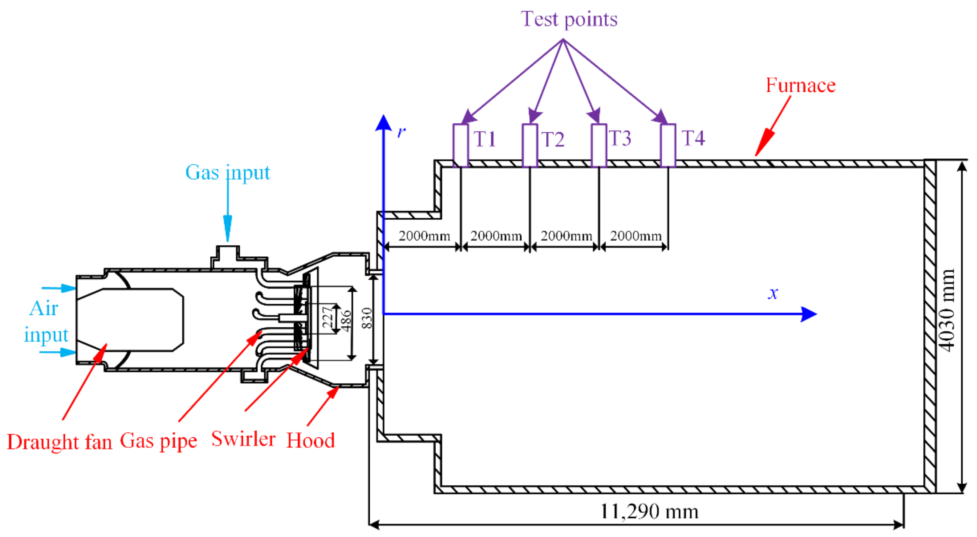
Funding

This work was supported by the National Natural Science Foundation of China (52075188), Pilot Project of Fujian Province (2018H0021), and Project of Quanzhou Science and Technology (2021G05).

Institutional Review Board Statement

Not applicable.

Informed Consent Statement

Not applicable.

Data Availability Statement

Not applicable.

Conflicts of Interest

The authors declare no conflict of interest.

References

  1. Wang, Y.; Sun, X.; Wang, B.; Liu, X. Energy saving, GHG abatement and industrial growth in OECD countries: A green productivity approach. Energy 2020, 194, 116833.1–116833.9. [Google Scholar] [CrossRef]
  2. Edland, R.; Normann, F.; Fredriksson, C.; Andersson, K. Implications of fuel choice and burner settings for combustion efficiency and NOx formation in PF-Fired iron ore rotary kilns. Energy Fuels 2017, 31, 3253–3261. [Google Scholar] [CrossRef]
  3. Filipponi, M.; Rossi, F.; Presciutti, A.; Ciantis, S.D.; Castellani, B.; Carpinelli, A. Thermal analysis of an industrial furnace. Energies 2016, 9, 833. [Google Scholar] [CrossRef] [Green Version]
  4. Xu, M.; Tu, Y.; Yu, W.; Yang, W.; Prabakaran, S. On the combination of fuel-rich/lean burner with MILD combustion for further NOx emission reduction. Energy Procedia 2019, 158, 1672–1677. [Google Scholar] [CrossRef]
  5. Wang, Y.; Zhou, Y.; Bai, N.; Han, J. Experimental investigation of the characteristics of NOx emissions with multiple deep air-staged combustion of lean coal. Fuel 2020, 280, 118416. [Google Scholar] [CrossRef]
  6. Li, J.; Chen, J.; Jin, W.; Yuan, L.; Hu, G. The design and performance of a RP-3 fueled high temperature rise combustor based on RQL staged combustion. Energy 2020, 209, 118480. [Google Scholar] [CrossRef]
  7. Li, X.R.; Zhao, W.H.; Gao, H.B.; Liu, F.S. Fuel and air mixing characteristics of wall-flow-guided combustion systems under a low excess air ratio condition in direct injection diesel engines. Energy 2019, 175, 554–566. [Google Scholar]
  8. Yu, Z.; Fan, X.; Gan, M.; Chen, X.; Lv, W. NOx reduction in the iron ore sintering process with flue gas recirculation. J. Oper. Manag. 2017, 69, 1570–1574. [Google Scholar]
  9. Fan, X.; Yu, Z.; Gan, M.; Chen, X.; Chen, Q.; Liu, S.; Huang, Y. Elimination behaviors of NOx in the sintering process with flue gas recirculation. ISIJ Int. 2015, 55, 2074–2081. [Google Scholar] [CrossRef] [Green Version]
  10. Qian, F.; Chyang, C.; Yeh, C.; Tso, J. Characteristics of a pilot-scale vortexing fluidized-bed combustor with flue gas recirculation (FGR): Effect of operating conditions on the combustion behavior. Energy Fuels 2010, 24, 6257–6265. [Google Scholar] [CrossRef]
  11. Dulin, V.; Chikishev, L.; Sharaborin, D.; Lobasov, A.; Tolstoguzov, R.; Liu, Z.; Shi, X.; Li, Y.; Markovich, D. On the flow structure and dynamics of methane and syngas lean flames in a model gas-turbine combustor. Energies 2021, 14, 8267. [Google Scholar] [CrossRef]
  12. Gao, W.; Yan, Y.; Shen, K.; Huang, L.; Gao, B. Combustion characteristic of premixed H2/air in the micro cavity combustor with guide vanes. Energy 2021, 239, 121975. [Google Scholar] [CrossRef]
  13. Liu, W.; Ouyang, Z.; Cao, X.; Na, Y. The influence of air-stage method on flameless combustion of coal gasification fly ash with coal self-preheating technology. Fuel 2019, 235, 1368–1376. [Google Scholar] [CrossRef]
  14. Khidr, K.I.; Eldrainy, Y.A.; El-Kassaby, M.M. Towards lower gas turbine emissions: Flameless distributed combustion. Renew. Sustain. Energy Rev. 2017, 67, 1237–1266. [Google Scholar] [CrossRef]
  15. Zhao, H.; Li, G.; Zhao, D.; Zhang, Z.; Sun, D.; Yang, W.; Li, S.; Lu, Z.; Zheng, Y. Experimental study of equivalence ratio and fuel flow rate effects on nonlinear thermoacoustic instability in a swirl combustor. Appl. Energy 2017, 208, 123–131. [Google Scholar] [CrossRef] [Green Version]
  16. Zhang, Z.; Liu, X.; Gong, Y.; Li, Z.; Zheng, H. Investigation on flame characteristics of industrial gas turbine combustor with different mixing uniformities. Fuel 2020, 259, 116297. [Google Scholar] [CrossRef]
  17. Hadef, R.; Lenze, B. Effects of co- and counter-swirl on the droplet characteristics in a spray flame. Chem. Eng. Process. 2008, 47, 2209–2217. [Google Scholar] [CrossRef]
  18. De Rosa, A.J.; Peluso, S.J.; Quay, B.D.; Santavicca, D.A. The effect of confinement on the structure and dynamic response of lean-premixed, swirl-stabilized flames. J. Eng. Gas. Turbine Power 2015, 138, 061507. [Google Scholar] [CrossRef]
  19. Legrand, M.; Nogueira, J.; Lecuona, A.; Nauri, S.; Rodríguez, P. Atmospheric low swirl burner flow characterization with stereo PIV. Exp. Fluids 2010, 48, 901–913. [Google Scholar] [CrossRef]
  20. Rosec, I.; Katranik, T.; Bakovi, U.V.; Seljak, T. Exhaust gas recirculation with highly oxygenated fuels in gas turbines. Fuel 2020, 278, 118285. [Google Scholar] [CrossRef]
  21. Yafei, Z.; Rui, L.; Yihua, D.; Qulan, Z. Combustion characteristics and NOx emission through a swirling burner with adjustable flaring angle. Energies 2018, 11, 2173. [Google Scholar]
  22. Daood, S.S.; Yelland, T.S.; Szuhanszki, J.; Pourkashanian, M.; Nimmo, W. Experimental investigation of NO reburning during oxy-coal burner staging. Energy Fuels 2019, 33, 1590–1602. [Google Scholar] [CrossRef]
  23. Zhou, L.X. Comparison of studies on flow and flame structures in different swirl combustors. Aerosp. Sci. Technol. 2018, 80, 29–37. [Google Scholar] [CrossRef]
  24. Wu, S.; Che, D.; Wang, Z.; Su, X. NOx emissions and nitrogen fate at high temperatures in staged combustion. Energies 2020, 13, 3557. [Google Scholar] [CrossRef]
  25. Zhu, X.; Li, R.; Li, D.; Peng, Z.; Qian, R. Experimental study and RANS calculation on velocity and temperature of a kerosene-fueled swirl laboratory combustor with and without centerbody air injection. Int. J. Heat Mass Transf. 2015, 89, 964–976. [Google Scholar] [CrossRef]
  26. Chen, S.; Xing, Y.; Li, A. CFD investigation on Low-NOX strategy of folded flame pattern based on fuel-staging natural gas burner. Appl. Therm. Eng. 2017, 112, 1487–1496. [Google Scholar] [CrossRef]
  27. Huang, L.; Kumar, K.; Mujumdar, A.S. Simulation of a spray dryer fitted with a rotary disk atomizer using a three-dimensional Computional Fluid Dynamic Model. Dry 2004, 22, 1489–1515. [Google Scholar] [CrossRef]
  28. Hinojosa, J.F.; Orozco, D.A.; Xaman, J. Experimental and numerical study of a ventilated room with located heat sources. Energy Sci. Eng. 2020, 146, 4020024. [Google Scholar] [CrossRef]
  29. Bidi, M.; Hosseini, R.; Nobari, M.R.H. Numerical analysis of methane–air combustion considering radiation effect. Energy Convers. Manag. 2008, 49, 3634–3647. [Google Scholar] [CrossRef]
  30. Li, S.; Xu, M.; Jia, L.; Tan, L.; Lu, Q. Influence of operating parameters on N2O emission in O2/CO2 combustion with high oxygen concentration in circulating fluidized bed. Appl. Energy 2016, 173, 197–209. [Google Scholar] [CrossRef]
  31. Fan, X.; Liu, C.; Xu, G.; Zhang, C.; Wang, J.; Lin, Y. Experimental investigations of the spray structure and interactions between sectors of a double-swirl low-emission combustor. Chin. J. Aeronaut. 2020, 33, 204–212. [Google Scholar] [CrossRef]
Figure 1. Schematic of the combustor geometry.
Energies 15 01097 g001
Figure 2. (a) Schematic diagram of the three-dimensional structure of the two-stage swirler; (b) the two-stage swirler used in the present experiments.
Energies 15 01097 g002
Figure 3. The flame of the burner in the furnace during the experiment.
Energies 15 01097 g003
Figure 4. Overall grid diagram of burner numerical simulation area.
Energies 15 01097 g004
Figure 5. Three-dimensional structure of (a) D65-30 and (b) CD65-30.
Energies 15 01097 g005
Figure 6. Axial velocity of D65-30 and CD65-30 at different axial positions.
Energies 15 01097 g006
Figure 7. Tangential velocity of D65-30 and CD65-30 at different axial positions.
Energies 15 01097 g007
Figure 8. Temperature distribution of D65-30 and CD65-30 on the center cross section.
Energies 15 01097 g008
Figure 9. Temperature distribution of D65-30 and CD65-30 near the furnace wall.
Energies 15 01097 g009
Figure 10. Local distribution of NOx concentration (ppm) of D65-30 and CD65-30 on the central cross section.
Energies 15 01097 g010
Figure 11. Three-dimensional diagram of different secondary-stage swirl blade angles.
Energies 15 01097 g011
Figure 12. Axial velocity of CD65-30, CD55-30, and CD45-30 at different axial positions.
Energies 15 01097 g012
Figure 13. Tangential velocity of CD65-30, CD55-30, and CD45-30 at different axial positions.
Energies 15 01097 g013
Figure 14. Temperature distribution of CD65-30, CD55-30, and CD45-30 in the center cross section.
Energies 15 01097 g014
Figure 15. Temperature distribution of CD65-30, CD55-30, and CD45-30 near the furnace wall.
Energies 15 01097 g015
Figure 16. NOx local distribution of CD65-30, CD55-30, and CD45-30 on the central cross section.
Energies 15 01097 g016
Figure 17. Three-dimensional structure of swirler with bluff structure.
Energies 15 01097 g017
Figure 18. Axial velocity distribution of D65-C45, D65-C35, and D65-C25 at different axial positions.
Energies 15 01097 g018
Figure 19. Tangential velocity distribution of D65-C45, D65-C35, and D65-C25 at different axial positions.
Energies 15 01097 g019
Figure 20. Temperature distribution of D65-C45, D65-C35, and D65-C25 in the center section.
Energies 15 01097 g020
Figure 21. Temperature distribution of D65-C45, D65-C35, and D65-C25 near the furnace wall.
Energies 15 01097 g021
Figure 22. NOx local distribution of D65-C45, D65-35, and D65-C25 on the central cross section.
Energies 15 01097 g022
Table 1. Parameters for the combustor.
ParametersValues
Diameter of combustor exit (mm)830
Blade number of first stage blade28
Blade number of secondary stage blade30
Install angel of first stage blade (°)60
Install angel of secondary stage blade (°)65
Vane thickness (mm)1
Table 2. Parameters for the experiments.
ParametersValues
Velocity of air inlet (m/s)18.92
Diameter of air inlet (m)0.35
Velocity of gas inlet (m/s)28
Diameter of gas inlet (m)0.141
Atmospheric temperature (K)298
Air inlet temperature (K)298
Excess air coefficient1.18
Outlet pressure (Pa)−70
Table 3. Comparison of experimental and numerical simulation results.
Thermocouple NumberExperimentSimulationError
T1798 °C827 °C3.6%
T21092 °C998 °C8.6%
T3985 °C956 °C2.9%
T4967 °C1008 °C4.2%
Table 4. Average NOx concentration at the furnace exit for D65-30, CD65-30.
NameNOx Concentration (ppm)
D65-3070.8
CD65-3057.3
Table 5. Average NOx concentration at the furnace exit for CD65-30, CD55-30, and CD45-30.
NameNOx Concentration (ppm)
CD65-3057.3
CD55-3076.2
CD45-3084.6
Table 6. Average NOx concentration at the furnace exit for D65-C45, D65-C35, and D65-C35.
NameNOx Concentration (ppm)
D65-C4564.9
D65-C3558.4
D65-C2557.9
Publisher’s Note: MDPI stays neutral with regard to jurisdictional claims in published maps and institutional affiliations.

