Review

A Review of Recent Best Practices in the Development of Real-Time Power System Simulators from a Simulator Manufacturer’s Perspective

RTDS Technologies Inc., 150 Innovation Drive, Winnipeg, MB R3T 2E1, Canada
*
Author to whom correspondence should be addressed.
Energies 2022, 15(3), 1111; https://doi.org/10.3390/en15031111
Submission received: 20 December 2021 / Revised: 25 January 2022 / Accepted: 30 January 2022 / Published: 2 February 2022

Abstract

:
As the power system undergoes continued change—widespread integration of inverter-based resources, electrification of transportation systems, decentralization, and increased digitization—the best practices for power system studies and device testing are also evolving. Electromagnetic transient (EMT) simulation is being used progressively by transmission and distribution system operators, equipment manufacturers, education and research institutions, and consultants who require a greater depth of analysis than is possible with traditional (RMS-based) system representation. Real-time simulation is becoming increasingly prevalent in the aforementioned verticals as it provides an efficient means of EMT analysis and also enables hardware-in-the-loop (HIL) testing of protection, control, and power devices. Real-time simulator manufacturers must continually develop their technology to improve the scope and accuracy of the power system components and phenomena that can be represented, the range and quantity of devices that can be subjected to HIL testing, and ease of use. This review paper will summarize recent advances and best practices in real-time simulation and hardware-in-the-loop testing from the perspective of RTDS Technologies, the manufacturer of the RTDS® Simulator. The focus is on power electronics modeling and testing, IEC 61850 simulation and interfacing, and graphical user interface advancements for this particular brand of a real-time simulator.

1. Introduction

Real-time digital power system simulation was initially developed in the 1980s for the purpose of testing high-voltage direct current (HVDC) project control equipment [1]. At the time, the de facto method for testing this equipment to verify dynamic performance prior to deployment was via analogue simulators—scaled-down physical models of the power system which were prohibitively large, expensive, and time-consuming to reconfigure [2]. Real-time digital simulators were developed in response to these issues; they offered a much more flexible solution for the closed-loop testing of not only HVDC controls but also transmission protection equipment. The applications of real-time simulation have evolved over time, and the technology has now been widely applied to a large range of projects including distribution automation, microgrids and renewable energy, wide area protection and control, power electronics, cybersecurity, and inverter testing [3].
Today, the practice of closed-loop testing, also known as hardware-in-the-loop (HIL) testing, has become relatively common in the context of proving the performance of grid modernization devices and schemes. HIL testing allows for testing many devices simultaneously and provides an opportunity for examining the interactions and interoperability of various protection, control, and power equipment. Real-time simulators allow electric utilities to de-risk vendor devices prior to deployment, protection and control manufacturers to perform comprehensive factory acceptance testing of devices and solutions, research institutions to test novel algorithms and approaches throughout the development process, and consultants to provide a greater depth of analysis than is possible with other tools [4].
Root mean square (RMS) dynamic modeling has long been the typical solution for system studies, particularly from the utility perspective. Electromagnetic transient (EMT) modeling is well-established in the industry but has not traditionally been considered necessary from a routine planning and operational studies point of view. However, due to changes in the power system and inherent limitations of RMS models, EMT simulation is growing in popularity (and indeed, necessity). The time-varying, instantaneous value output provided by EMT tools allows them to represent the behavior of the network over a relatively wide frequency range, providing a more detailed analysis than transient stability analysis and other phasor-based approaches. Using EMT modeling, it is possible to represent transients and other sub-cycle phenomena, behaviors diverging significantly from the fundamental frequency, and low-level control systems of inverter-based resources, all of which are critical characteristics of the modern grid and which cannot typically be captured by RMS modeling. EMT simulation is increasingly necessary for accurate dynamic representation of the modernized grid, which has become nigh unrecognizable from the conventional system dominated by centralized rotating machines.
Offline EMT simulations, which run on a standard PC, typically require a much longer computational time for a given circuit and operating scenario/event than an RMS model [3]. The high computational burden and inefficiency of running many simulations are among the reasons that EMT tools are not typically used for routine operations/planning. Real-time simulators, which run on dedicated parallel processing hardware rather than a PC, overcome this issue. These simulators are able to update the simulation output in real-time, meaning that all of the calculations required to solve the network via the Dommel Algorithm [5] are completed in real-world time equal to or less than the simulation timestep. The timestep, best understood as the time/period between consecutive outputs of the simulation, is a critical factor in determining the frequency bandwidth of signals that can be accurately represented by the real-time simulation. Generally, a 30–60 μs timestep is considered appropriate for the HIL testing of protection and control [6]. In the case of power electronics control testing, a much smaller timestep may be required—in the general range of 1–3 μs [7]. Though challenging from a processing perspective, maintaining real-time operation significantly increases the efficiency of EMT simulations relative to offline tools. Real-time operation also enables closed-loop testing, which is not possible with offline EMT or phasor-based tools. Increased efficiency and the possibility of HIL testing are the major justifications of real-time simulation.
The main components of a real-time simulator include parallel processing hardware, input/output hardware for interfacing external equipment with the simulation, and a graphical user interface through which the user can define their circuit and interact with the simulation. The models which make up the real-time simulator’s component library are also a critical and vast aspect of the technology. Models must accurately capture the dynamic behavior of complex power system components (machines, transformers, transmission lines, renewable energy equipment, etc.) while meeting the constraints of the Dommel Algorithm and hard real-time. Furthermore, as the typical devices deployed on the power system become more advanced and our knowledge of the characteristics and impact of various transient phenomena develops, engineers must test more complex device functionalities. The models must be enhanced to reflect these changes.
The manufacturers of real-time simulators must ensure that their technology meets the requirements of its users, and those requirements evolve alongside the real-world grid. Continual development is therefore required when it comes to not only the modeling library, but also the processing hardware, input/output facilities, and graphical user interface. This paper reviews recent advances and best practices in real-time simulation from the perspective of RTDS Technologies Inc. (Winnipeg, Manitoba, Canada), the developers of the RTDS Simulator [7]. The developments that are discussed have been implemented specifically for the RTDS Simulator’s hardware and software components and may or may not be present in other real-time simulators on the market. As this review paper is written specifically about the RTDS Simulator, developments from other real-time simulator manufacturers are out of the scope of this paper. The Supplementary Materials section includes a non-exhaustive list of other real-time simulator manufacturers along with links to their websites.
The following topics are the focus of this paper:
  • The development of a universal converter model to overcome modeling challenges associated with real-time power electronics simulation and the HIL testing of converter controls;
  • the addition of new features related to IEC 61850 Edition 2.0/2.1 and other developments related to the simulation and HIL testing of substation automation systems, and;
  • graphical user interface updates that significantly improve the user experience.
User requirements and experiences are a great driver of product development for real-time simulators. The advancements and best practices presented in this review both yielded and were the result of user feedback.
Further documentation on the advances and best practices presented in this paper are available in the References section or upon request.

2. Advances and Best Practices in Real-Time Simulation

2.1. Power Electronics Modelling and Testing

Power electronics are prevalent in the modern grid, with applications spanning HVDC and FACTS, renewable energy integration, drives, the electrification of transportation systems, and more. The high-fidelity representation of power electronic circuits and HIL testing of converter controls are therefore a vital aspect of modern real-time simulators. Real-time power electronics simulation is a challenge involving tradeoffs, and the approach taken to represent these systems has changed over time with the availability of processing hardware. This section reviews several different converter modeling approaches in chronological order of development, starting with the original capabilities of real-time simulators. The advantages and disadvantages of these methods are presented, and conclusions are made regarding best practices based on recent advancements.

2.1.1. Hardware Integration

This section is focused on modeling approaches and features, but the hardware integration of real-time power electronics models is also relevant. All of the models described below have been implemented directly on the central processing hardware of the real-time simulator. At the time of writing, the current generation of simulation hardware for the RTDS Simulator is based on a multicore processor (the IBM POWER8®) [8]. This processor was custom-integrated by the simulator manufacturer for the specific application of real-time simulation. The machine code runs directly on the processor without an underlying operating system. This is beneficial from an efficiency perspective and provides the manufacturer with a high level of control over the hardware platform. It also results in a highly deterministic system performance.
Experience suggests that implementation of real-time power electronics models directly on the central processor, rather than using an FPGA or other auxiliary hardware components with a real-time link to the central hardware, results in improved ease of use, long-term simulation stability, and error diagnosis. It also improves accessibility for this application area, allowing every entry-level simulator hardware configuration to carry out power electronics simulation.
As with all aspects of real-time simulation, processing burden is an important aspect of modeling, and a key tradeoff here. In general, more detailed models require a greater share of the real-time simulator’s available processing power. It is advantageous to develop models that provide reasonable levels of detail while reducing the burden on the processor so that larger and more complex networks can be simulated with a given hardware configuration (i.e., quantity of licensed cores). Models with a smaller simulation timestep generally have a larger computational burden [9], so in the context of power electronics, it is desirable to improve the range of switching frequencies that can be represented accurately at a given timestep rather than driving timesteps lower. This theoretically results in the ability to simulate more converters on a given quantity of simulation hardware. The voltage-sourced converter modeling approaches described below (Section 2.1.3, Section 2.1.4, Section 2.1.5) have improved over time at addressing these issues. The line-commutated converter models for the RTDS Simulator were able to address these issues as early as 1999.

2.1.2. Line-Commutated Converter Simulation

As the RTDS Simulator was originally developed for the testing of HVDC controls, the representation of line commutated converter (LCC) valves was a key original capability of the technology [1]. The thyristor-based six- and twelve-pulse valve groups of LCC schemes can be accurately simulated in the normal timestep environment (30–60 μs). To provide the necessary resolution for control signals coming into the simulation, a special algorithm was developed in 1999 in which the simulator’s digital input card samples a 6-bit firing pulse word from external controls every 10 nanoseconds. Based on this sampling rate, information is generated and sent to the valve regarding the precise time of arrival for firing pulses within the timestep. The valve can then correct for late sampling. This algorithm is still used today for LCC valve control testing with the RTDS Simulator [10].

2.1.3. Voltage-Source Converter Simulation via L/C Switching Models and Decoupled Resistively-Switched Models

Voltage-source converters (VSCs), on the other hand, present more of a challenge from a processing perspective. High-frequency pulse width modulation (PWM) control for VSCs requires a smaller simulation timestep, thereby demanding significantly more computational capacity. The refactorization of the network admittance matrix, which is necessary when representing changes in switching state with variable resistance, must be completed in a shorter time. In 2005, advances in processing technology led to the simulation of VSCs at timesteps in the range of 1.4–3.75 μs with the RTDS Simulator. This was originally performed in a special simulation environment which allowed for freely configurable power electronics simulations running on a dedicated processor in parallel to the main simulation [9]. The small timestep simulation was achieved via a constant conductance L/C discrete circuits switching method, a popular approach to representing changes in switching state without requiring the time-consuming refactorization of the admittance matrix in each timestep (as would be required with the switched-resistance approach) [11]. While this enables ON/OFF switching with a significantly reduced processing burden, thus enabling a relatively small simulation timestep, there are disadvantages to this approach:
  • The L/C switching method causes artificial switching losses associated with abruptly switching from a small inductor (representing the ON state) to a small capacitor (representing the OFF state) model. Losses increase with switching frequency until they are generally deemed excessive in the 3–5 kHz range [12];
  • The L/C representation can introduce current and voltage oscillation that appears as noise on the output waveforms;
  • The impedance of the switch is frequency-dependent, which limits its operational bandwidth. This places a limitation on the timestep in order to ensure that the ON/OFF impedance ratio is sufficiently large.
To address these issues, resistively-switched converter models were also made available in the small timestep environment, but they were decoupled from the surrounding network via a traveling wave interface. Matrix refactorization for all possible switching states was pre-calculated and stored prior to running the simulation case. The resistively-switched models were not subject to the same switching frequency limitations as the L/C switched models, but this approach also has disadvantages:
  • There was potential for the interface transmission line to contribute artificial series inductance and shunt capacitance to the system;
  • Due to memory limitations, it was only possible to represent a limited number of switches this way.
This small timestep environment was used successfully for many years by developers, manufacturers, and operators of power electronic controls. The modeling approaches were best practices at the time and produced results with relative conformity to site measurements [13].

2.1.4. Improved Multi-Rate Simulation Environment and Resistively-Switched Models

In 2017, a multicore processor (the IBM POWER8®) was adopted for the RTDS Simulator, representing a relatively large increase in processing capability and an opportunity for major improvements in power electronics simulation. Following this came the development of a predictive switching algorithm that allows for resistive ON/OFF transitions at a small timestep without requiring a traveling wave interface between the converter and the surrounding network [14]. Several fixed-topology power electronic converter models were developed based on this algorithm. These models allow for accurate representation of switching in the 30–50 kHz range with no artificial power losses and less stringent limitations on the quantity of switches in the power electronic circuit. Power losses for a resistively-switched neutral-point clamped (NPC) converter are compared with those of an L/C switched models in Table 1. Due to resistive switching, they do not suffer from the limited operational bandwidth of L/C switched models and can be run at up to 10 μs instead of being limited to 3.75 μs.
Multi-rate simulation is used to interface these power electronic circuits with the main timestep environment. Multi-rate simulation involves multiple subnetworks running on dedicated cores with timesteps that are integer fractions or multiples of each other. Data is shared between subnetworks in real-time at the relevant timestep. For example, a main timestep subnetwork running at 30 μs can be run in parallel with a subnetwork running at 3 μs, and data is exchanged every 30 μs.
Another key feature of these smaller timestep networks in the multi-rate simulation environment is that they can support a wide range of power system components—they are not limited to power electronics. Some components have been developed exclusively for use at a smaller timestep or with that environment in mind, but practically every model from the component library can be supported at a smaller timestep in the multi-rate environment. This allows users to simulate entire power systems in the smaller timestep environment if they wish, including machines, transmission lines, etc. A limit on the quantity of nodes on each dedicated core guides the user in the size and complexity of each subnetwork. These best practices in the multi-rate simulation result in a flexible environment that gives the user a high degree of control over the level of detail in the simulation and the processing load.

2.1.5. Average Value Models

Average value models (AVMs) should also be present in the real-time simulation library. AVMs are essentially a controlled voltage or current source and can be used to accurately represent the power profile of a converter without simulating the full switching behavior. Average models utilize the same control strategies and signals as fully-switched models, down to the modulation waveform. They cannot, however, be used to test controls at the firing pulse level for PWM schemes. Average value models have significantly reduced computation requirements compared to fully-switched converter models and can be run at any timestep in the multi-rate environment, ranging from 1 to 50 μs. These models are ideal when there is a limited quantity of simulation hardware, and the user is not interested in the high-frequency switching dynamics; converter harmonics are not represented when using an average model.

2.1.6. A Novel Universal Converter Model

For some applications today, it is important for real-time simulator users to achieve very high converter switching frequencies. However, the methods through which this is achieved impact the validity of the simulation and test results. The generation of artificial losses or noisy results, the long-term numerical stability of the simulation, and the hardware efficiency of the model are all critical considerations for real-time simulator manufacturers and users.
In 2021, the development of a new descriptor state-space (DSS) universal converter model (UCM) for the RTDS Simulator addressed several challenges of real-time power electronics simulation, achieving very high frequencies while overcoming issues of accuracy and stability [15]. This model has a special input type, called “Improved Firing”, which greatly reduces non-characteristic harmonics and significantly improves hardware efficiency while maintaining accuracy [16]. The DSS approach, which is used to represent the converter in deblocked mode, allows both sides of the converter to be represented by controlled sources with no delay, guaranteeing numerical stability and power balance. The predictive switching algorithm mentioned above is used to represent the converter in blocked mode. The UCM was developed for several fixed converter topologies: two-level, NPC and T-type three-level, boost, buck, and flying capacitor.
Like all power electronics simulation methods described in Section 2.1, the UCM is implemented directly on the central processing hardware of the RTDS Simulator. It is not decoupled at the DC bus, with no numerical interface between the converter model and surrounding network, thereby improving numerical stability and accuracy. It models both blocked and deblocked modes, representing the transition between blocked and deblocked states with improved accuracy. In addition to these advantages, the model is designed to be highly flexible and can accept three different types of inputs, which the user can select based on the level of controls to be tested and the detail required from the simulation. The input options are:
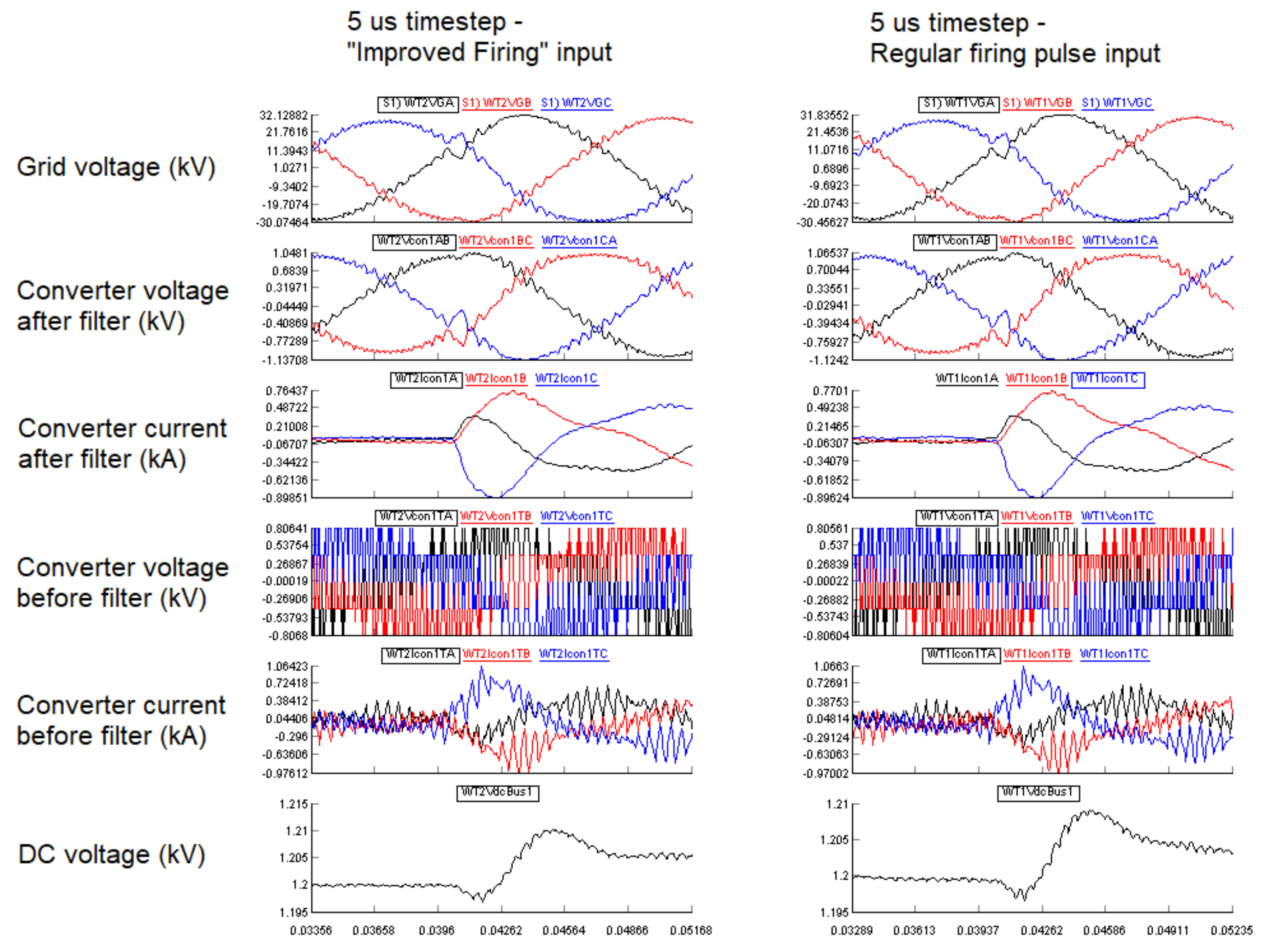
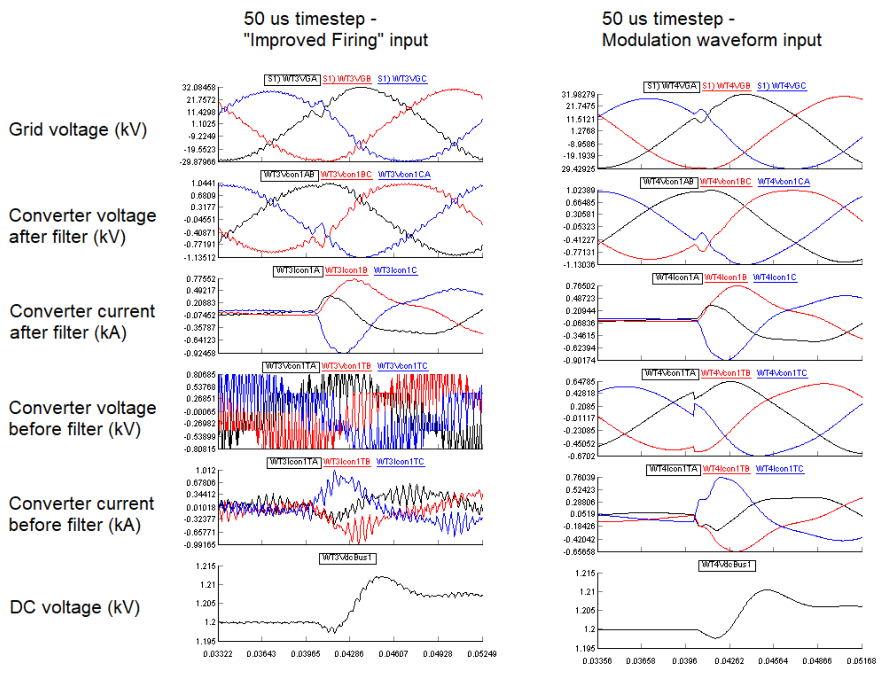
  • The converter model receives a sin wave as a modulation waveform, and the result is similar to that of an average value model, with some performance improvements. This option is available for a wide range of timesteps, in the range of 1–50 μs.
  • The converter model reads firing pulses (from an external controller or firing pulse generator within the real-time simulation) once per timestep, and the result is similar to the aforementioned resistively-switched converter models, covering switching frequencies in the 30–50 kHz range. This option is only available for subnetworks with a timestep of less than 10 μs.
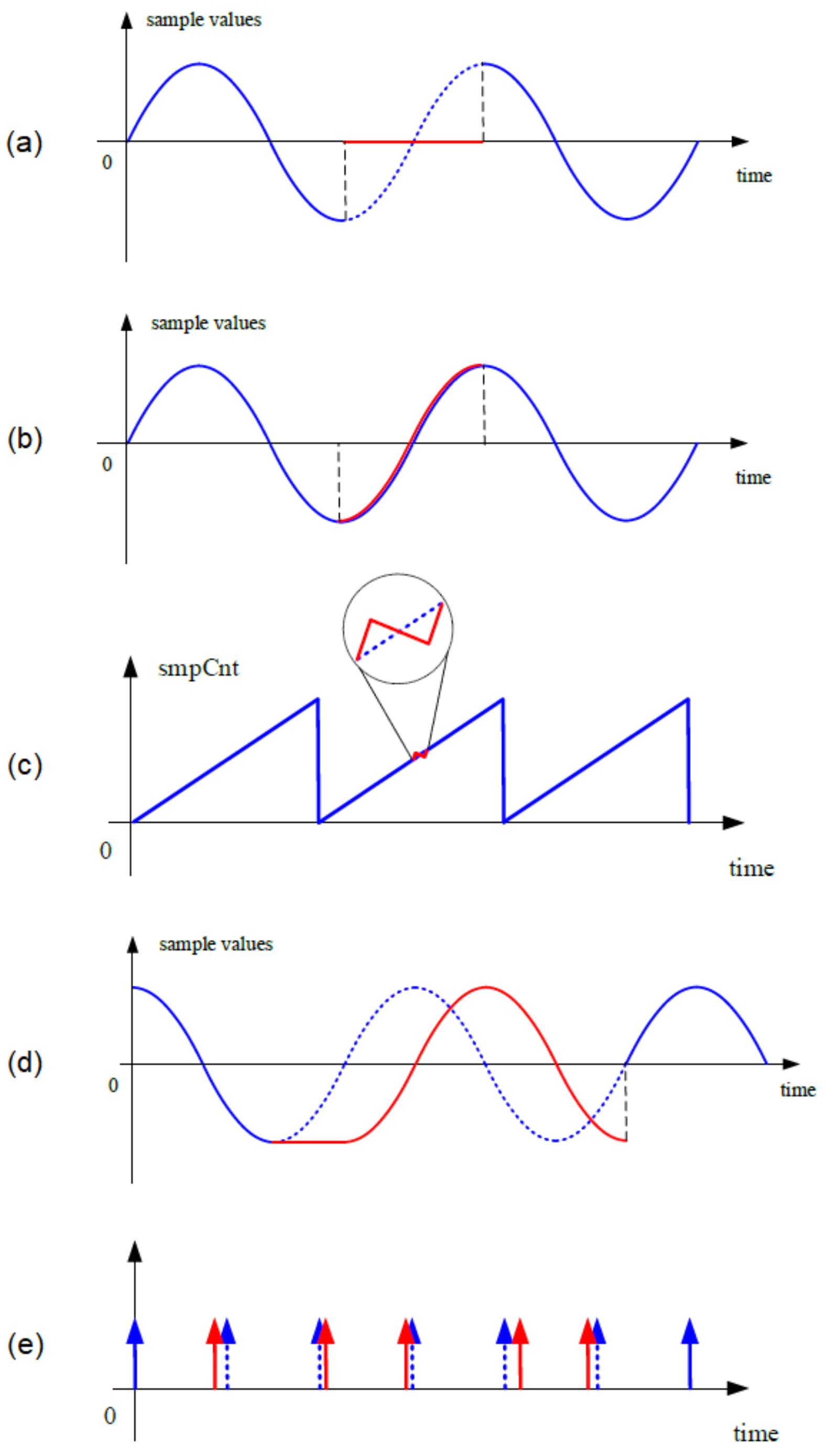
  • The “Improved Firing” algorithm has been developed to enhance the performance of the UCM for a wide range of timesteps. In this case, the converter model captures firing pulses at a very high resolution and calculates the portion of each timestep that the valve’s switches should be ON. This effectively allows for multiple ON/OFF transitions within each timestep. This novel option increases the range of switching frequencies that can be covered by the converter model; in subnetworks with a timestep of less than 10 μs, frequencies of up to 150 kHz can be tested. Perhaps more significantly, this feature can also be used in standard simulations with a timestep of 30–50 μs. It allows for frequencies of 2–3 kHz to be represented in detail without requiring a smaller timestep. The computational burden is therefore significantly reduced compared to previous models; several detailed converted models can be placed in simulations running on a single core.
This ability to increase the maximum firing resolution of the converter without a corresponding reduction in simulation timestep is an important aspect of the UCM’s design. For example, Defour presented a method to reduce power losses and state-overshoots of the L/C switching approach using cross-initialization of L/C switching elements [17]. While this approach addresses the issues with the L/C switching method, it still requires a smaller simulation timestep to achieve a greater firing resolution. A time-average method was proposed by Lian in [18] which significantly improves the accuracy for high-resolution firing of the simulated converter without requiring a smaller simulation timestep. When the time-average method was proposed, limitations in available processing hardware required the authors to introduce a delay between AC and DC sides of the converter amounting to one simulation timestep. This time delay has the potential to cause numerical stability issues. The aforementioned “Improved Firing” algorithm was developed for the UCM as a novel method of achieving higher-resolution firing without requiring a smaller simulation timestep (and therefore a greater calculation burden on the real-time simulation hardware), while also improving numerical stability by removing the time delay.
With the novel “Improved Firing” input, the performance of the UCM is equivalent to that of offline electromagnetic transient program models, which can take advantage of interpolation techniques as they do not need to maintain real-time. This is an advancement for real-time simulation. To summarize, the “Improved Firing” approach for the universal converter model affords the following benefits to users, all of which represent best practices in real-time power electronics simulation and HIL testing of power electronic controls:
  • It offers a non-decoupled, resistively-switched converter modeling option.
  • It can be run with the typical EMT simulation timestep of 30–50 μs. This allows for many detailed converter models to be allocated to a smaller simulation hardware configuration than was previously possible (i.e., fewer licensed cores). The UCM, therefore, benefits users not only with its improved numerical stability and accuracy over a greater range of switching frequencies but also with its hardware efficiency [19].
  • Switching frequencies of up to 150 kHz can be accurately tested without requiring timesteps in the nanosecond range.
  • Switching frequencies of 2–3 kHz can be accurately tested with timesteps in the 30–50 μs range.
Figure 1 and Figure 2 below show simulation results from a case using a two-level universal converter model in a STATCOM application. The simulation timestep and input type of the UCM were varied in order to show differences in performance. Note that the UCM input type can be changed via a dropdown menu within the component parameters.

2.2. IEC 61850 Modelling, Configuration, and Testing

Ethernet-based communication is prevalent in substation automation applications, and the use of standard protocols for interfacing external equipment in a hardware-in-the-loop interface is now a major application of real-time simulators [20]. IEC 61850 [21], with its provisions for Sampled Values (SV), GOOSE Messaging, and Manufacturing Message Specification (MMS), is the industry standard for digital substation communication. As the standard is revised and updated, real-time simulator manufacturers must ensure that the relevant aspects are reflected in their IEC 61850-related models and features. Advancements in IEC 61850 simulation are frequent.
This section will present recent advancements and best practices relating to Sampled Values, GOOSE Messaging, and their configuration via real-time simulation software features.

2.2.1. Sampled Values Manipulation

A selection of advancements in Sampled Values modeling was presented in [22], including a list of sampling rates that are supported by the RTDS Simulator in accordance with IEC 61850-9-2 and IEC 61869-9, as well as added support for routable SV. In this section, more recent advancements regarding real-time SV manipulation capabilities will be presented.
As substation automation systems increasingly rely on critical measurements delivered via SV, non-ideal and non-genuine SV streams present an increasing threat. At their worst, these communication contingencies can cause cascading failures and serious damage to the network [23]. Manufacturers of SV-compliant substation IEDs and the electric utilities who are responsible for their operation may therefore be interested in testing against invalid SV data packets and network disruptions. A report from the IEEE Power System Communications and Cybersecurity Committee [24] mentions real-time simulation as a method for conducting these tests. SV manipulation facilities were developed for the RTDS Simulator to enable this type of testing, which aids in identifying the vulnerabilities of these critical communication-based systems.
Interfacing to external devices from the RTDS Simulator via IEC 61850 is has been traditionally achieved by the GTNETx2 card—an Ethernet-based input/output card with two onboard FPGAs. More powerful, dedicated FPGA-based hardware, which is well-suited to applications requiring high-density calculations and precision timing, was recently adopted to meet the more stringent requirements set out in the IEC 61869-9 standard [25]. The capabilities of this hardware include:
  • Support for a wide range of SV sampling rates, including those defined in IEC 61869-9 and several retained for IEC 61850-9-2-LE backward compatibility [26]. This includes a sampling rate of 96 kHz as per IEC 61869-9, the preferred sampling rate for high-bandwidth DC instrument transformer applications.
  • Support for an SV sampling rate of 250 kHz. This capability was developed based on the requirements of RTDS Simulator users with ultra-high-bandwidth applications such as HVDC control and protection testing [27].
  • Support for SV stream and data manipulation options, which are summarized below and described in additional detail in [28].
Both data and stream manipulation are supported by the new feature. Twelve options for data manipulation allow users to alter specific parts of each SV packet, and five options for stream manipulation allow for higher-level disruptions to be applied to the stream.
Data manipulation is supported for the following aspects of the packet:
  • VLAN Priority;
  • VLAN ID;
  • Application ID;
  • Length of SV packet;
  • Reserved 1;
  • Reserved 2;
  • Number of ASDU;
  • Configuration revision;
  • Sample count;
  • Destination MAC address;
  • Source MAC address;
  • Stream identification;
Stream manipulation is supported in the following modes, which are shown in Figure 3:
  • Stop/resume: Simulates the loss of packets on the network by stopping and re-starting SV publishing from the operator’s console.
  • Duplicate: Simulates a problematic network topology by duplicating SV packets.
  • Swap: Simulates the non-sequential arrival of packets, due to problematic network routing, by swapping the order of two SV packets.
  • Delay: Simulate undesirable network latency by delaying SV packets.
  • Jitter: Simulate variable latency by adding positive/negative jitter to the stream. Jitter can be controlled with a resolution of 10 ns.
Data and stream manipulation is supported for a wide range of timesteps in the 1–50 μs range, and almost all manipulation modes are supported by all SV sampling rates in the IEC 61869-9 standard. The exception is that Duplicate and Jitter stream manipulation is not supported for the 250 kHz sampling rate. The inclusion of SV manipulation, especially with features for high-resolution jitter, is a best practice for modern real-time simulators.

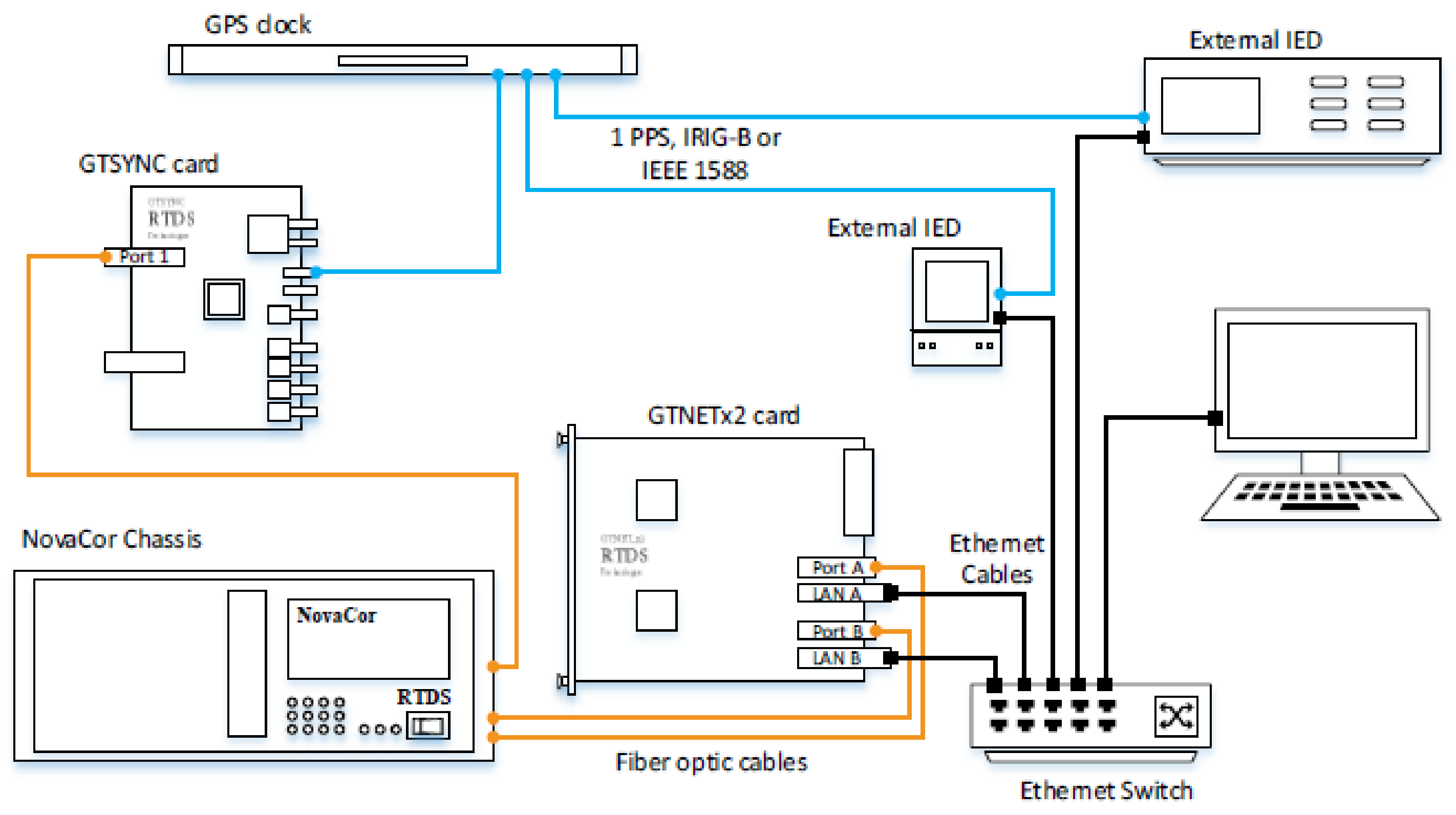
2.2.2. Support for PTP Synchronization Profiles

There has been increasing adoption of Precision Time Protocol (PTP) [29] as the preferred synchronization method by electric utilities and manufacturers of protection and control equipment, particularly in IEC 61850 applications [30]. PTP profile support has therefore been developed for the RTDS Simulator’s synchronization card (responsible for synchronizing the simulation timestep to an external clock).
Three PTP profiles are supported: IEC/IEEE 61850-9-3 Power Utility Profile, IEEE C37.238-2011, and IEEE C37.238-2017. Experience suggests that these are currently the most popular (and therefore requested) PTP profiles for real-time simulator users. Supporting PTP will be an important feature of real-time simulators moving forward.

2.2.3. Capability Advancements and Support for IEC 61850-8-1 Edition 2.0/2.1

The IEC published IEC 61850 Edition 2.1 in February of 2020 as an amendment to the existing Edition 2.0. The new documents included key differences from previous versions of the standard, which are important to reflect in real-time simulator models and capabilities. The GSEv7 component was developed for the RTDS Simulator to provide GOOSE and MMS support which conforms to the updated standard. The new component increases the resemblance, from a data model and communication interface perspective, between simulated IEDs and real-world commercial IEDs. The RTDS Simulator’s GTNETx2 network interface card is used to facilitate the interface between external devices and the Simulator via GSEv7 (see Figure 4).
Previous GOOSE messaging components were restricted to one type of generic logical node class for output data: GGIO. The new component supports all output data logical node classes defined in IEC 61850-7-4, making GSEv7 much more flexible and realistic from a data binding perspective.
There have also been updates to the quantity of logical devices, logical nodes, datasets, data items, and streams that can be represented with each GSEv7 component. Previously, each GOOSE messaging component had rigid limits on the quantity of logical devices and logical nodes simulated. GSEv7 is much more capable and flexible, with no rigid limit on the number of logical devices per IED simulated, or on the number of logical nodes per logical device. Additionally, there was previously a limit of five datasets per component, which were application-specific (one reserved for switchgear operations). The new component can hold up to 32 datasets which are application-independent. The component can publish up to 16 GOOSE messaging streams, which are also application-independent, and subscribe to up to 32 GOOSE streams per component. The total quantity of data items that can be published and subscribed to has also increased significantly to 512. These upgrades represent not only improved capabilities but also increased flexibility; the user has more control over the applications of the component.
The GSEv7 component has significantly expanded MMS capabilities as well. Previously, one Report Control Block (RCB) was supported per component, which was upgraded significantly to 16 RCBs. Additional flexibility was built into MMS reporting features: reporting, like other features of the model, was made application-independent (previously only supported for switchgear applications). Report datasets were also made completely user-configurable. MMS capabilities can be disabled in the GSEv7 component if the user does not require the component to represent an MMS server.
The updated component also includes support for key new features introduced in IEC 61850 Ed. 2, such as the simulation feature. This advanced technique to test IEDs via logical isolation is supported for both GOOSE and SV protocols. The IED’s inputs are temporarily replaced by test inputs (called “simulated” inputs). The user can switch the IED from regular to simulated inputs through control action, such as an MMS command from a remote client. This simplifies the testing process and makes it much more convenient, as the physical connections no longer need to be modified. The simulated data is only distinguishable from normal inputs by the IED via a Simulation Flag in the header of the IEC 61850 data stream. The simulation feature is integrated into the real-time simulator via a controllable input that allows the user to set and reset a Simulation Flag parameter in the communication frames of published GOOSE and SV streams.
Subscription monitoring is another significant new Ed. 2 feature which is supported by the updated real-time simulator model. Subscription monitoring uses particular Logical Nodes that are dedicated to expressing the active/inactive status of the stream subscription (including whether the subscribed IED is delivering simulated data). Subscription monitoring is useful for diagnostics. Each IED within the simulation can subscribe to subscription monitoring, and the monitoring values can be monitored within the operator’s console of the real-time simulation or in a remote MMS client.
Simulator developers should participate actively in industry committees and working groups dedicated to various applications of real-time simulation (such as the UCA International User’s Group in the case of IEC 61850 [31]) and be familiar with the most up-to-date versions of industry standards and practices. Subjects and features relevant to real-time simulation can then be distilled and added to the product development pipeline.

2.2.4. An Improved IED Configuration Tool

To configure simulated IEDs, users build a generic data model with a chosen set of Logical Nodes (including necessary data), which are then grouped into Logical Devices. The publishing dataset must then be created, with associated GOOSE control blocks. Communication parameter specification and subscription mapping are typically the final steps. Modern real-time simulators must include facilities for carrying out these critical steps in simulated IED configuration.
An improved IED Configuration Tool (ICT) was developed for the RTDS Simulator alongside the updated GSEv7 component. The ICT, which is a standalone PC application launched from the real-time simulation software, allows users to carry out the following:
  • Configure IEDs simulated by GSEv7 components.
  • Carry out data binding (mapping input and output data to signals in the simulation).
  • Generate a Configured IED Description (CID) files for every GSEv7 component, which contains Substation Configuration Language (SCL) files for each simulated IED within it.
  • Import SCL files from external devices connected to the real-time simulator.
The ICT is designed to be user-friendly and convenient. Each ICT project can contain many GSEv7 components, allowing the user to configure all IEDs from a simulation case in a single ICT project window. The ICT also performs a number of error checks and provides meaningful feedback to the user regarding corrections to the configuration. It is designed to be used by both highly experienced IEC 61850 engineers and users who are relatively new to the standard.
Finally, it should be noted that the ICT provides backward compatibility to previously released versions of the GSE component in the real-time simulation component library. There is also compatibility worked into the real-time simulation case-building environment itself: when simulation cases from older versions of the software are opened, GSE components are automatically converted to GSEv7.

2.3. Graphical User Interface Improvements

Real-time simulators depend not only on hardware (e.g., parallel processing and input/output hardware) and a vast model library (e.g., power and control system component models), but also a graphical user interface (GUI) through which the user can configure the power system model and interact with the real-time simulation. The capabilities, features, design, and speed of the GUI are important aspects of the real-time simulator, affecting the user’s productivity and the time required to train personnel to operate the simulator.
The RTDS Simulator’s GUI, RSCAD, has evolved in the decades since its inception. Many developments have been informed by discussions with users who have noticed productivity bottlenecks, opportunities for automation, and ease of use issues. Recent advancements to RSCAD were significant enough to warrant a new GUI name, RSCAD FX, and have significantly improved the overall experience for users [32] and represent best practices in real-time simulator GUI development.

2.3.1. Speed

RSCAD FX was designed for fast, smooth operation, even when working with very large simulation cases. In addition to the operating speed of the GUI itself, the speed of the compiler is an important aspect of real-time simulators. Long compile times may be frustrating to users, especially during the troubleshooting process or batch simulation when frequent compiles are necessary. RSCAD’s compiler has been written and optimized for speed, with compile times typically in the range of 5–10 s.

2.3.2. Look and Feel

The appearance and general dynamic behavior of a real-time simulator’s GUI is a non-trivial factor in its overall usability and effectiveness. The GUI’s appearance should reflect not only software industry standards but also popular programs within the power system industry. Transitioning from other power system study tools (e.g., load flow, phasor-based programs, offline EMT simulation, open-loop hardware testing kits) to real-time simulation introduces entirely new considerations for the engineer, such as processing hardware constraints and input/output signal conditioning. If the GUI is reminiscent of other familiar power system softwares, most of the learning curve can be focused on the hardware-related elements.
A customizable GUI layout, where the window can be configured to display modules such as the case canvas, component library, and error messages in different sizes and areas, is beneficial for the user. For example, the ability to view two case canvases side by side within the GUI window, and drag and drop components between them, increases productivity. The ability to undock various modules so they become their own window is also helpful.

2.3.3. Automated Component Naming

A key factor in improving user productivity in a real-time simulator’s GUI is the reduction or mitigation of compile errors that are not related to the validity of the circuit or the simulator’s hardware configuration. These superficial compile errors, often related to arbitrary limitations or constraints of the GUI, can significantly affect the user learning curve and project timelines. Automated component naming is a good example of a feature that reduces trivial compile errors and should be included in modern real-time simulator GUIs as a best practice.
Automated component naming mitigates errors related to duplicate component names in the circuit-building environment. In large cases—for example, a case reflecting a portion of an electrical utility’s transmission network—there are often many instances of components such as generators, transformers, transmission line terminals, loads, etc. Without an automated component naming feature, placing many of these models in the case without manually editing the name parameters will generate compile errors. Compilers generally require unique names not only for the components themselves but also for individual signals within the components. This can amount to hundreds or even thousands of required unique names. A sophisticated automated naming feature shifts this burden of work almost entirely from the user to the real-time simulation software.
Best practice for automated naming involves the use of an enumerator—an embedded attribute in every component in the real-time simulator’s modeling library. The user can opt to enable an enumerator for the signal name parameters within the components. The value of the enumerator can be automatically incremented as components are copied and pasted or moved from the library to the canvas in the case-building environment. The incrementation of the enumerator automatically yields unique component and signal names through many instances of the same component.
Ideally, the automated naming feature is customizable by the user. In the RSCAD FX GUI, the enumerator can appear anywhere within the signal name and can be part of a more complex, user-defined string of characters. It can be incremented as a decimal, hexadecimal, uppercase, or lowercase letter. These options result in highly customizable signal names that are easily identified when the time comes for them to be manipulated, monitored, and plotted during the real-time simulation. In this way, customizable automated naming not only reduces compile errors but also improves the ease of collaboration between colleagues within the same organization or between organizations, as it is much more convenient to administer consistent and intuitive signal names.
In RSCAD FX, the user can enable or disable enumerator incrementation for each component. It is also possible to flatten signal names, i.e., to resolve enumerators to their current values and reset this to be the new base name of the parameter name. A new enumerator can then be added to the end of the flattened name and incremented from zero. The flattening feature allows for entire groups of components to be copied and pasted without duplication of names.

2.3.4. Buswork Tool

The bulk of the time that the user spends in the circuit-building environment should be dedicated to parametrizing power system components, building control circuits, and configuring input/output signals, rather than dealing with tediousness and errors related to circuit drawing layout. A buswork tool, called Wire Mode, was developed for RSCAD FX in order to expedite the process of laying out buses, wires, and related connections on the circuit drawing canvas.
Instead of using a bus component from the library and manipulating it via stretching and rotation, users can switch into buswork drawing mode and easily draw buses using a special cursor. When the buswork tool cursor is activated, a series of mouse clicks and movements allow for the convenient drawing of complex buswork. Keyboard shortcuts also allow the user to activate and deactivate the buswork tool, allowing for a seamless transition between placing components on the canvas and connecting them with wires.

3. Discussion

Real-time simulator manufacturers must remain aware of relevant issues facing electrical utilities, protection and control equipment manufacturers, researchers and educators, and power industry consulting engineers. This means participating actively in industry committees and working groups, staying attentive to industry publications and events, and communicating with real-time simulator users. The result is a truly state-of-the-art technology that is able to reflect the complexities of the modern grid and the challenges facing its equipment, operators, and contributors.
This paper has described a non-exhaustive selection of recent advancements developed for the RTDS Simulator, a particular brand of real-time simulator. The advancements described have broadened the scope of phenomena that can be represented, increased the variety of devices that can be interfaced with the simulation, improved the accuracy and fidelity of real-time power system studies, and improved testing outcomes for real-time simulator users.

4. Conclusions

The significant deliverables of this review paper are several recent developments for the RTDS Simulator which represent best practices in real-time simulator development:
  • A novel universal converter model for power electronics modeling that uses a proprietary algorithm to achieve high-resolution firing without requiring a reduced simulation timestep. The model overcomes several challenges associated with real-time power electronics modeling, including fictitious power losses, numerical stability issues due to decoupling/delay, and the typically high computational burden of detailed switching models.
  • Enhancements to substation automation simulation facilities which reflect new features/requirements of IEC 61850 Edition 2.0/2.1 and other industry developments. This includes improved GOOSE Messaging capabilities, an IED Configuration Tool for enhanced configuration of GOOSE Messaging streams, Sampled Values manipulation options, and support for PTP synchronization profiles.
  • An updated graphical user interface (GUI) with improved speed, look, and feel. The GUI includes new features such as automated component naming and an efficient buswork drawing tool.

Supplementary Materials

The searchable online Knowledge Base for the RTDS Simulator is available at https://knowledge.rtds.com/ (accessed on 20 December 2021). A list of technical publications related to the RTDS Simulator is available at https://knowledge.rtds.com/hc/en-us/categories/360001905033-Technical-Publications (accessed on 20 December 2021). Other real-time power system simulator manufacturers include, but are not limited to the following. More information on their products can be found at the websites: OPAL-RT Technologies (https://www.opal-rt.com/) (accessed on 20 January 2022), Typhoon HIL Inc. (https://www.typhoon-hil.com/) (accessed on 20 January 2022).

Author Contributions

K.S. curated, analyzed, and interpreted the data, and prepared the manuscript. P.F. reviewed and edited the manuscript. All authors have read and agreed to the published version of the manuscript.

Funding

This research received no external funding.

Institutional Review Board Statement

Not applicable.

Informed Consent Statement

Not applicable.

Data Availability Statement

The data presented in this study are available on request from the corresponding author.

Acknowledgments

The authors acknowledge the contributions of the research and development teams at RTDS Technologies Inc., who were instrumental in developing the advancements discussed in this paper.

Conflicts of Interest

The authors declare no conflict of interest.

References

  1. Duchen, H.; Lagerkvist, M.; Lovgren, N.; Kuffel, R. Validating the Real Time Digital Simulator for HVDC Dynamic Performance Studies. In Proceedings of the ICDS, Montreal, QC, Canada, 28–30 May 1997; pp. 245–250. [Google Scholar]
  2. Arendt, L.; Giesbrecht, J.; Kuffel, R.; Wang, X.; Wierckx, R.; Woodford, D. Enhanced performance of a conventional HVDC analogue simulator with a real-time digital simulator. In Proceedings of the Eleventh Power Systems Computation Conference, Avignon, France, 30 August–3 September 1993; Volume 1, pp. 663–669. [Google Scholar]
  3. Sidwall, K.; Zakonsjek, J. Experiences and future potential: Real-time simulation for de-risking converter-connected generation, HVDC interconnections, and modern protection. In Proceedings of the CIGRE SEERC Conference, Vienna, Austria, 30 November 2021. [Google Scholar]
  4. Badrzadeh, B.; Emin, Z. The Need for Enhanced Power System Modelling Techniques and Simulation Tools; Reference Papers; CIGRE Electra: Brisbane, Australia, 2020; No. 308; pp. 54–55. [Google Scholar]
  5. Dommel, H.W. Digital Computer Solution of Electromagnetic Transients in Single- and Multiphase Networks. IEEE Trans. Power Appar. Syst. 1969, 88, 388–399. [Google Scholar] [CrossRef]
  6. Kuffel, R.; Maguire, T.; Wierckx, R.; Yoon, Y.; Kim, T.; Cha, S. Overview & Comparison of Power System Analysis and Study Tools. In Proceedings of the IERE Workshop, Taejon, Korea, September 1999; pp. 63–69. [Google Scholar]
  7. Kuffel, R.; Giesbrecht, J.; Maguire, T.; Wierckx, R.P.; McLaren, P. RTDS—A Fully Digital Power System Simulator Operating in Real Time. In Proceedings of the International Conference on Energy Management and Power Delivery, Singapore, 21–23 November 1995. [Google Scholar]
  8. Friedrich, J.; Le, H.; Starke, W.; Stuechli, J.; Sinharoy, B.; Flurh, E.; Dreps, D.; Zyuban, V.; Still, G.; Gonzalez, C.; et al. The Power8TM Processor: Designed for Big Data, Analytics, and Cloud Environments. In Proceedings of the IEEE International Conference on IC Design & Technology, Austin, TX, USA, 28–30 May 2014. [Google Scholar]
  9. Maguire, T.; Giesbrecht, J. Small Time-Step (≤2 μs) VSC Model for the Real Time Digital Simulator. In Proceedings of the ICPST, Montreal, QC, Canada, 19–23 June 2005; pp. 1–6. [Google Scholar]
  10. RTDS Technologies Inc. RSCAD® Power System Components Manual; RTDS Technologies Inc.: Winnipeg, MB, Canada, September 2018; pp. 744–768. [Google Scholar]
  11. Wang, K.; Xu, J.; Tai, N.; Tong, A.; Hou, J. A Generalized Associated Discrete Circuit Model of Power Converters in Real-Time Simulation. IEEE Trans. Power Electron. 2019, 34, 2220–2233. [Google Scholar] [CrossRef]
  12. Qi, L.; Steurer, M.; Woodruff, S. Study of power loss of small time-step VSC model in RTDS. In Proceedings of the 2007 IEEE Power Engineering Society General Meeting, Tampa, FL, USA, 24–28 June 2007; pp. 1–7. [Google Scholar] [CrossRef]
  13. Forsyth, P.; Hasler, J.; Larsson, T.; Maguire, T. Voltage Source Converter modeled in RTDS—Experiences and comparison with field results. In Proceedings of the International Conference on Power Systems Transients, Lyon, France, 4–7 June 2007. [Google Scholar]
  14. Maguire, T.; Elimban, S.; Tara, E.; Zhang, Y. Predicting Switch ON/OFF Statuses in Real Time Electromagnetic Transients Simulations with Voltage Source Converters. In Proceedings of the IEEE Conference on Energy Internet and Energy System Integration, Beijing, China, 20–22 October 2018. [Google Scholar]
  15. RTDS Technologies Inc. Webinar and Demo: The New Universal Converter Model—A Revolution in Real-Time Power Electronics Simulation. June 2021. Available online: https://www.rtds.com/events/webinar-and-demo-ucm/ (accessed on 20 December 2021).
  16. RTDS Technologies Inc. RSCAD® Universal Converter Models Manual; RTDS Technologies Inc.: Winnipeg, MB, Canada, 4 March 2021. [Google Scholar]
  17. Dufour, C. Method and System for Reducing Power Losses and State-Overshoots in Simulators for Switched Power Electronic Circuit. U.S. Patent 9,665,672, 30 May 2017. [Google Scholar]
  18. Lian, K.L.; Lehn, P.W. Real-time simulation of voltage source converters based on time average method. IEEE Trans. Power Syst. 2005, 20, 110–118. [Google Scholar] [CrossRef]
  19. Cheng, Z.; Narayanan, S.; Holbach, J.; Stevens, J.; Cummings, M.; Rohde, R.; Guo, C.; Encarnacion, N. Investigating Inverter-Based Resources Impacts on the Transmission Line Protection via Hardware-in-the-loop Simulation. In Proceedings of the RTDS Technologies’ User Spotlight Series 2.0, Winnipeg, MB, Canada, 24 November 2021; Available online: https://onlinexperiences.com/scripts/Server.nxp?LASCmd=AI:4;F:QS!10100&ShowUUID=B4241EF5-805B-403B-B4C5-81DF97DB6AD6&AffiliateData=rtds&Referrer=https%3A%2F%2Fwww.rtds.com%2Fevents%2Fuss2%2F (accessed on 20 January 2021).
  20. Desjardine, M.; Forsyth, P.; Mackiewicz, R. Real Time Simulation Testing Using IEC61850. In Proceedings of the IPST 2007, Lyon, France, 4–7 June 2007. [Google Scholar]
  21. International Electrotechnical Commission. Communication Networks and Systems for Power Utility Automation—ALL PARTS. Available online: https://webstore.iec.ch/publication/602 (accessed on 23 November 2021).
  22. Sidwall, K.; Forsyth, P. Advancements in Real-Time Simulation for the Validation of Grid Modernization Technologies. Energies 2020, 13, 4036. [Google Scholar] [CrossRef]
  23. Rajkumar, V.S.; Tealane, M.; Ştefanov, A.; Palensky, P. Cyber Attacks on Protective Relays in Digital Substations and Impact Analysis. In Proceedings of the 2020 8th Workshop on Modeling and Simulation of Cyber-Physical Energy Systems, Sydney, Australia, 21 April 2020; pp. 1–6. [Google Scholar] [CrossRef]
  24. Udren, E.A.; Vandiver, B.; Anderson, J.; Antonova, G.; Apostolov, A.; Beaumont, P.; Beresh, R.; Brunner, C.; Calero, F.; Chelmecki, C.; et al. Application of Ethernet Networking Devices Used for Protection and Control Applications in Electric Power Substations: Report of Working Group P6 of the Power System Communications and Cybersecurity Committee of the Power and Energy Society of IEEE. In Proceedings of the 2021 74th Conference for Protective Relay Engineers (CPRE), College Station, TX, USA, 22–25 March 2021; pp. 1–88. [Google Scholar] [CrossRef]
  25. RTDS Technologies Inc. Webinar and Demo: Enhanced IEC 61850 Sampled Values Streaming with the RTDS Simulator’s GTFPGA Unit. 29 September 2021. Available online: https://www.rtds.com/events/iec-61850-gtfpga/ (accessed on 20 December 2021).
  26. RTDS Technologies Inc. RSCAD® Control Library Manual: GTFPGA-SV-V3; RTDS Technologies Inc.: Winnipeg, MB, Canada, 2021; p. 1394. [Google Scholar]
  27. Jin, S.; Stott, T. Evaluate HVDC Protection and Control Schemes using High Speed Process Bus Technology. In Proceedings of the 17th International Conference on AC and DC Power Transmission, Online, 8 July–8 December 2021. [Google Scholar]
  28. Jin, S.; Gurusinghe, D.R.; Ouellette, D.S. Evaluating Ethernet based Protection with IEC 61850 SV Data and Stream Manipulation. In Proceedings of the Advanced Power System Automation and Protection (APAP), Jeju, Korea, 11–14 October 2021. [Google Scholar]
  29. IEC/IEEE 61850-9-3 Edition 1.0 2016-05Communication Networks and Systems for Power Utility Automation—Part 9-3: Precision Time Protocol Profile for Power Utility Automation, IEC/IEEE International Standard: Piscataway, NJ, USA, 31 May 2016; pp. 1–18.
  30. Junior, P.; Martins, C.M.; Bernardino, R.C.; Pereira, P.S. Analysis of PTP Synchronization Behavior with IEC 61850 Process Bus. In Proceedings of the 2019 IEEE PES Innovative Smart Grid Technologies Conference—Latin America (ISGT Latin America), Gramado, Brazil, 15–18 September 2019; pp. 1–6. [Google Scholar]
  31. Mackiewicz, R. Overview of IEC 61850 and Benefits. In Proceedings of the 2006 IEEE PES Power Systems Conference and Exposition, Atlanta, GA, USA, 29 October–1 November 2006; pp. 623–630. [Google Scholar]
  32. RTDS Technologies Inc. Webinar and Demo: Meet RSCAD FX! April 2021. Available online: https://www.rtds.com/events/meet-rscad-fx/ (accessed on 20 January 2022).
Figure 1. Simulation results for two different input modes of the universal converter model (“Improved Firing”, left; regular firing pulse, right), running at 5 microseconds in a two-level STATCOM application. Event shown is an AC reference voltage change from 1.0 to 1.1 pu.
Energies 15 01111 g001
Figure 2. Simulation results for two different input modes of the universal converter model (“Improved Firing”, left; modulation waveform, right), running at 50 microseconds in a two-level STATCOM application. Event shown is an AC reference voltage change from 1.0 to 1.1 pu.
Energies 15 01111 g002
Figure 3. The RTDS Simulator’s stream manipulation options for IEC 61850 Sampled Values: (a) stop/resume; (b) duplication; (c) swap; (d) delay; (e) jitter.
Energies 15 01111 g003
Figure 4. Connections between the real-time simulator and external equipment via the GTNETx2 card for network interfacing.
Energies 15 01111 g004
Table 1. Power losses for resistively-switched (Substep environment) vs. L/C associated discrete circuit (ADC) models of an NPC converter.
PWM Switching Frequency (Hz)Power Losses for Resistively-Switched Model (via Predictive Switching)Power Losses for L/C ADC Model 1
12600.18%3.0%
30600.22%6.5%
1 Losses are defined as the difference in power entering the DC side vs. leaving the AC side of the converter.
Publisher’s Note: MDPI stays neutral with regard to jurisdictional claims in published maps and institutional affiliations.

