Abstract
In order to solve the problem of uneven air inlet flow in the guide channel of autoclave, three optimization schemes for the guide plate were proposed. The flow field in the guide channels of autoclave was simulated and analyzed by the realizable k-epsilon turbulence model and dynamic boundary method. The results show that the three optimization schemes have a certain effect on solving the problem of uneven air inlet flow in each guide channel, but some of them also have some negative effects. The integration of the three optimization schemes effectively increases the total air inlet flow of the guide channels; the increase ratio reaches 4.15%, improves the flow-field characteristics at the outlet of the guide channels and greatly reduces the difference in the air inlet flow in the left and right guide channels; the difference ratio drops from 62.61% to 5.37%.
1. Introduction
Autoclave is a large horizontal pressure vessel, which is widely used in industries that require high temperature or pressure production process, such as heavy metal smelting, refractory brick immersion coal infiltration, heating or cooling of composite glass, cable vulcanization, medicine, aerospace industry, insulation materials and military industries, etc. Due to the particularity of the process conditions, the flow-field characteristics in the autoclave and the uniformity of temperature-field changes have a very important influence on its working performance.
As the application scenarios and actual working conditions of the autoclave have become more and more complicated, its internal flow-field characteristics and temperature-field characteristics have become the focus of research by experts and scholars. Li et al. [1,2] simulated the three-dimensional heat transfer and fluid flow in an autoclave with a length-to-diameter ratio of 10 under nonuniform heating conditions and analyzed the influence of baffles on the fluid flow characteristics in the autoclave. Bohne et al. [3] studied the heat transfer in a small experimental autoclave through calorimeter measurements and fluid dynamics models and observed a complex turbulent flow pattern with a locally varying heat transfer coefficient. Schimmel et al. [4] conducted machine-learning-related research on the fluid-flow and temperature-field simulation of autoclave. Zhang et al. [5] established a simulation method of the flow field and temperature field in the working process of the autoclave through Xflow software and analyzed the influence of the process parameters of the autoclave on its internal flow field and temperature field. Appa et al. [6,7] studied the mass transfer process of the fluid in the autoclave by numerical simulation and verified it based on experimental data. They found that the mass transfer process of the fluid in the autoclave was poor and proposed an estimate empirical formula for fluid mass transfer based on the experimental data. Li et al. [8] studied the turbulent motion characteristics of the fluid in the semicircular tube jacket on the inner wall of the autoclave by numerical simulation and studied the effect of the average Reynolds number Re, δ and τ on the velocity field and flow resistance of the fluid in the jacket. At the same time, the average axial velocity and the secondary flow function distribution of the fluid in the jacket were obtained based on the orthogonal spiral coordinate system. Antonucci et al. [9,10] analyzed the heat transfer phenomenon that occurred during the operation of the autoclave and compared it with experimental data from industrial autoclaves; they also conducted extensive tests on the semi-theoretical method developed. Gao et al. [11] analyzed the flow-field characteristics and temperature rise process in the effective area of the autoclave through numerical simulation methods and verified the accuracy of the simulation through physical experiments. Li et al. [12] studied the flow field and temperature field of the fluid in the autoclave based on the autoclave molding simulation software and optimized the position of the components in the autoclave, thereby improving the efficiency of process design and improving the quality of components operation. Kluge et al. [13] predicted the temperature distribution of various parts in the autoclave by using computational fluid dynamics methods and compared the consistency of the prediction results with experimental data. It was found that more detailed inlet velocity curves and more advanced turbulence models may produce better consistency with experimental data. Jimmy et al. [14] used the particle image velocimetry method to qualitatively measure the flow characteristics of the fluid in the autoclave. At the same time, they studied the heat transfer of the fluid in the autoclave by measuring the temperature at multiple locations during the heating process. Hassim [15] studied the flow pattern of the autoclave through the Fluent software, and the results showed that the air flow velocity in the rear area of the autoclave was relatively uniform. Booth et al. [16] studied the Reynolds number flow in the pipeline in the autoclave and studied the corresponding turbulent energy dissipation rate. Meng [17] analyzed the influence of the length of the specimen in the autoclave on the influence of the fluid turbulence intensity and turbulent kinetic energy on its side by numerical methods and obtained that the optimal length of the specimen was 126 mm. Antonucci et al. [18,19] proposed a new method to analyze the heat transfer in the autoclave. The method has been applied to patch wing panels and was validated by comparison with the experimental data. Ghamlouch et al. [20] designed and manufactured an autoclave model based on the law of similarity, which allows the use of PIV technology to measure the flow field around a representative real industrial molding and to characterize the heat transfer with the help of a thermal imager. Bhatti et al. [21] recounted the latest trends in computational fluid dynamics in an editorial. In addition, some scholars have studied the characteristics of other fluid peristaltic flows [22,23,24] and temperature fields [25,26], which has certain reference significance for the selection and setting of simulation models and boundaries [27,28]. The flow-field characteristics and temperature-field characteristics in the autoclave have been studied above, but the research on the flow-field characteristics in the guide channels in the autoclave is rarely involved.
The autoclave studied in this paper is mainly used for heating and cooling composite glass. The uniformity of the air inlet flow of each guide channel in the autoclave and the velocity characteristics of the air at the outlet of the guide channels have a very important influence on the overall flow-field characteristics and temperature-field distribution characteristics in the autoclave. Therefore, in order to solve the problem of uneven air inlet flow in each guide channel in the autoclave, three optimization schemes for the guide plate are proposed. Quantitative and qualitative analysis is performed on the air inlet flow characteristics of the guide channels in the autoclave and the velocity characteristics at the outlet of guide channels under each optimization scheme to measure the optimization effect. The research results provide a certain reference for the design and optimization of the guide-plate structure in the relevant autoclave.
2. Research Object and Model Theory
Figure 1 shows the overall structure of the autoclave for heating and cooling composite glasses. The autoclave is mainly composed of autoclave body, fans, guide plates, baffles, a heating row and a cooling row and other components.
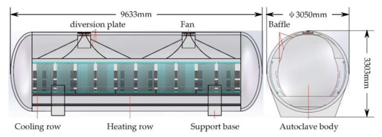
Figure 1.
Structure diagram of autoclave.
During the working process, the air in the autoclave enters the area between the two baffles and the two sidewalls inside the autoclave through the guide channels on both sides of the autoclave under the action of the fans and diffuses into the area between the two baffles in the autoclave under the action of the guide plates and flows upward into the fans to complete the entire cycle. The heating row and the cooling row located near the two sidewalls in the autoclave heat or cool the air to realize the control of the temperature in the autoclave. It can be seen from the above analysis of the air distribution and flow directions that the flow-field characteristics in the autoclave, especially the air inlet flow characteristics in the guide channels and the flow characteristics of the air at the outlet of the guide channels, have a very important influence on the change efficiency and uniformity of the temperature field in the autoclave.
The air in the autoclave has a high flow velocity driven by the fans, so the realizable k-ε turbulence model is selected when simulating the air flow characteristics in the autoclave. Based on the standard k-ε turbulence model, a new dissipation rate equation is added to the realizable k-ε turbulence model, which improves the vortex viscosity. The realizable k-ε turbulence model has higher accuracy and better calculation performance in rotating uniform shear flow, free flow (jet and mixing layer), channel flow, etc.
The realizable k-ε turbulence model is a typical two-equation model, which is the turbulent kinetic energy equation and the dissipation rate equation. The turbulent kinetic energy equation k is shown in Equation (1).
and the dissipation rate equation ε is shown in Equation (2).
where Gk is the turbulent energy generated by the laminar velocity gradient; σk is the turbulent Prandtl number of the turbulent flow energy equation; σ is the turbulent Prandtl number of the dissipation rate equation; μt is the turbulent viscosity; Sε is the user defined primary phase; C1ε, C2, C3ε and Cμ are constants which equal to 1.44, 1.90, 1.90 and 0.99, respectively.
The dynamic boundary method is used to simulate the rotation of the fans in actual work of the autoclave and the air suction and discharge process caused by the rotation with the fans.
3. Analysis of Simulation Results
This article mainly focuses on the research and analysis of the air inlet flow characteristics in the guide channels and the flow-field characteristics at the outlet of the guide channels in the autoclave. Therefore, in the simulation analysis, the heating row and cooling row are ignored, and the corresponding flow-field model is established and meshed. The realizable k-ε turbulence model and dynamic boundary method introduced above are used to simulate and analyze the air inlet flow characteristics of the guide channels and the air-flow-field characteristics at the outlet of the guide channels. The given motor rotation speed is 1500 r/min.
Figure 2 shows the characteristics of the fluid flow field at the outlet of the guide channels of the autoclave. Figure 2a is the air velocity contour. It can be seen from the figure that the air velocity at the outlet of the left guide channel is the largest, the maximum speed is greater than 6 m/s, and the air velocity at the outlet of the middle guide channel is the smallest. Figure 2b is the air turbulent kinetic energy contour, which has the same variation law as the velocity cloud map. Figure 2c is the velocity vector of the air, where the arrow direction indicates the air flow direction and the arrow color indicates the air flow velocity. It can be seen from the figure that the air-flow direction at the outlet of the guide channels is tangent to the guide plates and the angle between the tangent at the end of the guide plates and the vertical direction is larger. Therefore, the air flowing through here diffuses and flows to the left and right ends of the autoclave along the tangential direction of the guide plates instead of flowing down in the vertical direction into the area between the two baffles in the autoclave, which has a negative effect on the efficient circulation of the flow field and the uniform change of the temperature field in the autoclave.
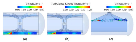
Figure 2.
The flow-field characteristics at the outlet of the guide channel. (a) Velocity contour; (b) turbulent kinetic energy contour; (c) velocity vector.
At the same time, it can be seen from Figure 2c that under the effect of the guide plate structure, the air flow velocity at the outlet of the left and right guide channels is quite different. The reason for the above phenomenon is that, on the one hand, the flow velocity of the air entering each guide channel is different, and on the other hand, the structure of the guide plates makes the amount of air flowing into each guide channel very uneven. This is also not conducive to the efficient circulation of the flow field and the uniform change of the temperature field in the autoclave.
In order to quantitatively analyze the air inlet flow of each guide channel, three monitoring surfaces shown in Figure 3 are established at the outlet of the guide channels to monitor the mass flow of the air passing through each monitoring surface. At the same time, it also provides an intuitive and quantitative analysis and explanation for the optimization effect of subsequent guide plates structure optimization.
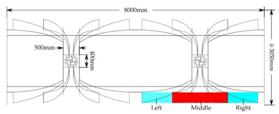
Figure 3.
Schematic diagram of the mass flow monitoring faces of each guide channel.
Through analysis, the mass flow of air flowing into each guide channel under the action of the guide plates is shown in Table 1. It can be seen from Table 1 that under the effect of the existing guide plates, the air inlet flow of each guide channel decreases from left to right, and there is a big difference in the air inlet flow between the left and right guide channels, which is 0.098139 kg/s (the difference ratio is 62.61%), which seriously affects the efficiency of flow-field circulation and the uniformity of temperature-field changes in the autoclave.

Table 1.
Air mass flow of each guide channel.
4. Structural Optimization Analysis
Aiming at the problem of uneven air inlet flow between the left and right guide channels and poor flow-field characteristics at the outlet of guide channels under the existing guide plates structure, three optimization schemes for the guide plates and baffles on both sides of the fans are proposed. The optimization effect of each optimization scheme is evaluated through quantitatively analyzing the air inlet flow of each guide channel and the total air inlet flow of the guide channels before and after optimization.
4.1. Optimized Scheme 1: The Top Part of Guide Plates
In order to solve the problem of the large difference in the air inlet flow of the left and right guide channels in the autoclave, optimization scheme 1, as shown in Figure 4, is proposed. It can be seen from Figure 4 that, under the guide plates before optimization shown in Figure 4a, the air flows directly into each guide channel when it flows out of the fans. Optimization scheme 1 deletes the top part of guide plate 1 and guide plate 2 to form the optimized guide plates shown in Figure 4b, which allows the air to have more time and space for diffusion and distribution before entering the guide channels, thereby reducing the unevenness of the air inlet flow of the left and right guide channels. Taking the two guide plates shown in Figure 4 as examples, respectively, the simulation analysis of the air inlet flow characteristics of the guide channels is carried out so as to obtain the results of the air inlet flow characteristics of the guide channels in the autoclave before and after optimization.
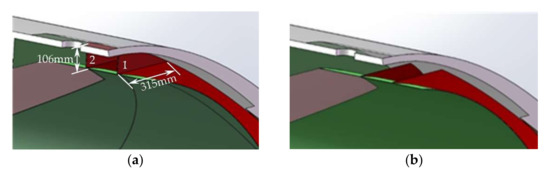
Figure 4.
Optimized scheme 1: (a) before optimization; (b) after optimization.
Through analysis, the mass flow of air entering each guide channel before and after optimization is shown in Table 2. It can be seen from Table 2 that the air inlet flow of the left guide channel in the autoclave after optimization has decreased to a certain extent, while the air inlet flow of the right guide channel has increased significantly. The difference of the air inlet flow between the left and right guide channels is obviously reduced to 0.023733 kg/s (the difference ratio is 16.80%). However, at the same time, it can be seen from the figure that optimization scheme 1 also causes a significant decrease in the air inlet flow of the middle guide channel in the autoclave.
Table 2.
Air mass flow of each guide channel before and after optimization.
The total air inlet flow of the guide channels in the autoclave is also an important index to measure its flow-field characteristics. It can be seen from Table 2 that the air inlet flow of the right guide channel increases, while that of the left and middle guide channels decreases. The total mass flow of air entering the guide channels before and after optimization is expressed by adding up the air inlet flow of the left, middle and right guide channels.
Through simulation analysis, the total mass flow of air entering the guide channels before and after optimization is shown in Table 3. It can be seen from Table 3 that while reducing the difference of the air inlet flow between the left and right guide channels in the autoclave, the total air mass flow of the guide channels in the optimized autoclave has a certain increase, and the increase ratio is 0.60%.
Table 3.
Total air mass flow of guide channels before and after optimization.
4.2. Optimized Scheme 2: The Shape of Guide Plates
For the problem of poor air flow characteristics at the outlet of the guide channels in the autoclave, optimization scheme 2, as shown in Figure 5, is proposed. It can be seen from Figure 5 that, under the guide plates before optimization shown in Figure 5a, when the air flows to the outlet of the guide channels, it diffuses and flows along the tangential direction of the guide plates to the left and right ends of the autoclave. In optimization scheme 2, the end of the guide plates is tangent to the vertical direction so as to form the optimized guide plates structure shown in Figure 5b, which makes the air to flow downwards in the vertical direction into the area between the two baffles in the autoclave when it flows to the outlet of the guide channels, thereby improving the circulation characteristics of the air in the autoclave. Taking the two guide plates shown in Figure 5 as examples, respectively, the simulation analysis of the air inlet flow characteristics of the guide channels is carried out so as to obtain the results of the air inlet flow characteristics of the guide channels in the autoclave before and after optimization.
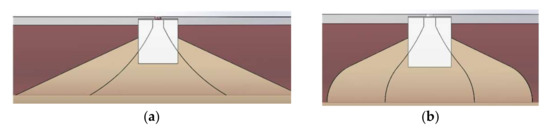
Figure 5.
Optimized scheme 2: (a) before optimization; (b) after optimization.
The velocity vector diagram of air at the outlet of the guide channels under the guide plates obtained through analysis is shown in Figure 6b. It can be seen from the figure that the air at the outlet of the guide channels in the autoclave after optimization flows vertically downwards along the end of the guide plates, and its flow characteristics have been well improved.
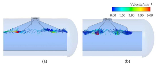
Figure 6.
Air mass flow of each guide channel before and after optimization: (a) before optimization; (b) after optimization.
Through analysis, the mass flow of air entering each guide channel before and after optimization is shown in Table 4. It can be seen from the table that the difference in the airflow velocity at the outlet of the left and right guide channels in the autoclave after optimization is still large.
Table 4.
Air mass flow of each guide channel before and after optimization.
Through simulation analysis, the total mass flow of air entering the guide channels before and after optimization is shown in Table 5. It can be seen from Table 5 that the total air mass flow of the guide channels in the autoclave after optimization has a certain decrease, and the decrease ratio is 2.44%.
Table 5.
Total air mass flow of guide channels before and after optimization.
4.3. Optimized Scheme 3: The Shape of Baffles
Aiming at the problem of the large difference in air inlet flow between the left and right guide channels during the working process of the autoclave, optimization scheme 3, shown in Figure 7, is proposed. It can be seen from Figure 7 that, under guide plates before optimization shown in Figure 7a, when the air flows out from the fans, it enters each guide channel along the tangential direction of the fans’ rotation. Optimization scheme 3 optimizes the baffles on both sides of the fans into arc-shaped guide plates, thus forming the optimized guide plates on both sides of the fans as shown in Figure 7b. The optimized guide plates make a part of the air flow tangent to the fans rotation direction before entering the guide channels, while the other part of air is tangent to the end of the optimized guide plates as shown in Figure 7c. It can be seen from Figure 7c that, compared with the baffles on both sides of the fans before the optimization, the direction of the combined velocity of the air shift to the middle guide channels when air passes through the optimized guide plates. As a result, more air flows into the remaining two guide channels, reducing the unevenness of the air inlet flow of the left and right guide channels. Taking the two guide plates shown in Figure 7 as examples, respectively, the simulation analysis of the air inlet flow characteristics of the guide channels is carried out so as to obtain the results of the air inlet flow characteristics of the guide channels in the autoclave before and after optimization.
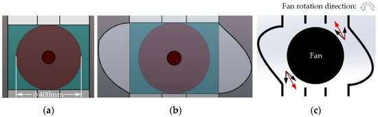
Figure 7.
Optimized scheme 3: (a) before optimization; (b) after optimization; (c) flow direction.
Through simulation analysis, the mass flow of air entering each guide channel before and after optimization is shown in Table 6. It can be seen from Table 6 that after optimization, the air inlet flow of the left guide channel in the autoclave has decreased to a certain extent and the air inlet flow of the middle and right guide channel has increased to a certain extent. The above analysis shows that optimization scheme 3 effectively introduces part of the air in the left guide channel into the middle guide channel, thereby reducing the difference in air inlet flow between the left and right guide channels, which is 0.057811 kg/s (the difference ratio is 42.77%).
Table 6.
Air mass flow of each guide channel before and after optimization.
Through simulation analysis, the total mass flow of air entering the guide channels before and after optimization is shown in Table 7. It can be seen from Table 7 that while reducing the difference of the air inlet flow between the left and right guide channels in the autoclave, the total air mass flow of the guide channels in the optimized autoclave has a certain increase, and the increase ratio is 3.55%.
Table 7.
Total air mass flow of guide channels before and after optimization.
4.4. Overall Optimization
The quantitative analysis of the air inlet flow of each guide channel and the total air inlet flow of the guide channels and the qualitative analysis of the flow-field characteristics at the outlet of the guide channels in the autoclave under three optimization schemes are performed. It can be seen from analysis that while the three optimization schemes have a certain effect on solving the problem of uneven air inlet flow in each guide channel, some of them also have some negative effects. In this section, the above three optimization schemes are integrated to form an overall optimized autoclave model based on the autoclave model before optimization. Taking the two autoclaves before and after optimization as an example, the air inlet flow of each guide channel and the total air inlet flow of the guide channels and air flow characteristics at the outlet of the guide channels are simulated and analyzed so as to obtain the results of the flow-field characteristics of guide channels in the autoclave before and after optimization.
The velocity vector diagram of air at the outlet of the guide channels under the guide plates after optimization obtained through analysis is shown in Figure 8b. It can be seen from the figure that the air at the outlet of the guide channels in the autoclave after optimization flows vertically downwards along the end of the guide plates, and its flow characteristics have been well improved. At the same time, it can be seen from the figure that the difference in air flow velocity at the outlet of the left and right guide channels in the autoclave is significantly reduced after optimization.
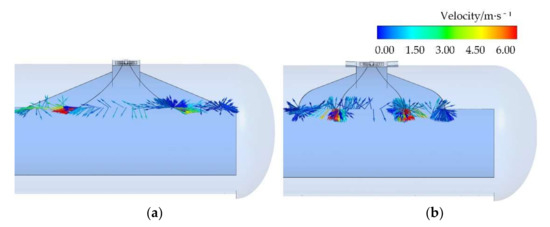
Figure 8.
Air mass flow of each guide channel before and after optimization: (a) before optimization; (b) after optimization.
Through analysis, the mass flow of air entering each guide channel before and after optimization is shown in Table 8. It can be seen from Table 8 that after optimization, the air inlet flow of the left guide channel in the autoclave has decreased significantly and the air inlet flow of the right guide channel has increased significantly, while the air inlet flow of the middle guide channel has basically not changed. At the same time, it can be seen from the figure that the difference in the air inlet flow of the left and right guide channels in the autoclave after optimization is greatly reduced to 0.005906 kg/s (the difference ratio is 5.37%). That is, through overall optimization, while maintaining the same amount of air inlet flow in the middle guide channel, the problem of uneven airflow in the left and right guide channels in the autoclave has been well solved.
Table 8.
Air mass flow of each guide channel before and after optimization.
Through simulation analysis, the total mass flow of air entering the guide channels before and after optimization is shown in Table 9. It can be seen from Table 9 that the total air mass flow of the guide channels in the optimized autoclave has a significant increase, and the increase ratio is 4.15%.
Table 9.
Total air mass flow of guide channels before and after optimization.
5. Discussion
The model graphs of autoclave are derived from the software Solidworks and the software Visio, the graphs of air velocity vector are derived from the software Ansys Fluent and the data in the table is analyzed by software Ansys Fluent.
6. Conclusions
Aiming at the problem of uneven air inlet flow in the guide channels in the autoclave and poor air flow characteristics at the outlet of the guide channels, three optimization schemes for guide channels and baffles on both sides of the fans are proposed. Through the simulation analysis of the air inlet flow characteristics of the guide channels and the air flow characteristics at the outlet of the guide channels in the autoclave under each scheme, the following conclusions are drawn:
(1) Optimization scheme 1 solves the problem of the large difference in the air inlet flow of the left and right guide channels in the autoclave by reducing the air inlet flow of the left guide channel and increasing the air inlet flow of the right guide channel. Optimized scheme 1 causes a slight increase in the total air inlet flow of the guide channels in the autoclave, and at the same time causes a certain decrease in the air inlet flow of the middle guide channel.
(2) Optimization scheme 2 effectively improves the air flow characteristics at the outlet of the guide channels, but the difference in airflow velocity at the out of the left and right guide channels is still large. At the same time, optimization scheme 2 resulted in a certain decrease in the total amount of air entering the guide channels in the autoclave.
(3) Optimization scheme 3 reduces the difference in the air inlet flow of the left and right guide channels in the autoclave by reducing the air inlet flow of the left guide channel while maintaining the same air inlet flow in the right guide channel. At the same time, optimization scheme 3 increases the air inlet flow of the middle guide channel and the total air inlet flow of the guide channels in the autoclave.
(4) Integrating the above three optimization schemes effectively solves the problem that the air flow direction at the outlet of the guide channel points to the two ends of the autoclave along the tangential direction of the guide plates and the large difference in airflow velocity between the left and right guide channels.
(5) Integrating the above three optimization schemes greatly reduces the difference in the air inlet flow in the left and right guide channels by reducing the air inlet flow in the left guide channel and increasing the air inlet flow in the right guide channel while keeping the air inlet flow in the middle guide channel basically unchanged. The difference of the air inlet flow between the left and right guide channels is reduced from 0.098139 kg/s (the difference ratio is 62.61%) to 0.005906 kg/s (the difference ratio is 5.37%). The overall optimization scheme makes the total air inlet flow of the guide channels in the autoclave increase substantially, and the increase ratio reaches 4.15%.
Author Contributions
Conceptualization, D.G. and Y.S.; methodology, Z.Z.; software, Y.S. and T.G.; validation, D.G., Y.S. and Y.L.; formal analysis, B.C.; investigation, Y.J. and Y.S.; resources, J.Z. and Y.S.; data curation, Y.S.; writing—original draft preparation, Y.S.; writing—review and editing, D.G.; visualization, Y.S.; supervision, D.G.; project administration, D.G. and Y.S.; funding acquisition, D.G. All authors have read and agreed to the published version of the manuscript.
Funding
This research was funded by the Science and Technology Research Key Projects of Hebei Provincial Institution of Higher Education (No. ZD2020120), the National Natural Science Foundation of China (No. 52075468, No. 52005430, No. 52005428 and No. 51905481), the China Postdoctoral Science Foundation (No. 2020M671784), the Natural Science Foundation of Hebei Province (No. E2020203052, No. E2021203099 and No. E2021203108), the Open Fund Project of Shaanxi Provincial Key Laboratory of Hydraulic Technology (No. YYJS2022KF04),the Natural Science Foundation of Zhejiang Province (No. LY22E050012), the Open Project Funding of Jiangsu Provincial Key Laboratory of Advanced Manufacture and Process for Marine Mechanical Equipment and the Open Project Funding of Fluid Power Transmission and Control Laboratory of Yanshan University.
Institutional Review Board Statement
Not applicable.
Informed Consent Statement
Not applicable.
Data Availability Statement
Not applicable.
Conflicts of Interest
The authors declare no conflict of interest.
References
- Li, H.M.; Wang, G.X.; Evans, E.A. Three-dimensional flow of solution in an industry-size hydrothermal autoclave subjected to non-uniform heating-effects of a baffle on flow and temperature separation. J. Cryst. Growth 2004, 271, 257–267. [Google Scholar] [CrossRef]
- Li, H.; Wang, G.X.; Evans, E.A. Numerical Analysis of Three-Dimensional Flow in an Industry-Size Hydrothermal Autoclave Subjected to Non-Uniform Heating. In Proceedings of the ASME 2002 Joint U.S.-European Fluids Engineering Division Conference, Montreal, QC, Canada, 14–18 July 2002. [Google Scholar]
- Bohne, T.; Frerich, T.; Jendrny, J. Simulation and validation of air flow and heat transfer in an autoclave process for definition of thermal boundary conditions during curing of composite parts. J. Compos. Mater. 2018, 52, 1677–1687. [Google Scholar] [CrossRef]
- Schimmel, S.; Tomida, D.; Saito, M. Boundary Conditions for Simulations of Fluid Flow and Temperature Field during Ammonothermal Crystal Growth—A Machine-Learning Assisted Study of Autoclave Wall Temperature Distribution. Crystals 2021, 11, 254. [Google Scholar] [CrossRef]
- Zhang, C.Q.; Bao, Y.D.; An, L.L. Temperature Field Simulation of Autoclave Forming Process Based on XFlow. Aeronaut. Manuf. Technol. 2020, 63, 76–83. [Google Scholar]
- Appa, H.; Deglon, D.A.; Meyer, C.J. Numerical modelling of hydrodynamics and gas dispersion in an autoclave. Hydrometallurgy 2013, 131–132, 67–75. [Google Scholar] [CrossRef]
- Appa, H.; Deglon, D.A.; Meyer, C.J. Numerical modelling of mass transfer in an autoclave. Hydrometallurgy 2014, 147–148, 234–240. [Google Scholar] [CrossRef]
- Li, Y.X.; Hua, B.; Wu, J.H. Flow Characteristics of Turbulent Fluid in the Inner Half-coil Jackets of an Autoclave. Chin. J. Process Eng. 2011, 11, 913–918. [Google Scholar]
- Antonucci, V.; Giordano, M.; Imparato, S.I. Analysis of Heat Transfer in Autoclave Technology. Polym. Compos. 2010, 22, 613–620. [Google Scholar] [CrossRef]
- Antonucci, V.; Giordano, M.; Imparato, S.I. Autoclave manufacturing of thick composites. Polym. Compos. 2012, 23, 902–910. [Google Scholar] [CrossRef]
- Gao, Y.F.; Qu, C.H. Numerical Simulation About Heat-Fluid Coupling in Autoclaves. Ind. Furn. 2012, 34, 37–39. [Google Scholar]
- Li, C.L.; Wen, Y.Y. Study on Numerical Simulation Technology for Autoclave Heat-Fluid Coupling of Composites. Aeronaut. Manuf. Technol. 2017, 19, 92–100. [Google Scholar]
- Kluge, J.N.E.; Lundström, T.S.; Westerberg, L.G. Modelling heat transfer inside an autoclave: Effect of radiation. J. Reinf. Compos. 2016, 35, 1126–1142. [Google Scholar] [CrossRef]
- Jimmy, O.; Lars-Göran, W.; Staffan, L.T. Flow and heat transfer inside an autoclave. In Proceedings of the 11th International Conference on Flow Processing in Composite Materials, Auckland, New Zealand, 9–12 July 2012. [Google Scholar]
- Hilmi, H.M. A Study of Flow Pattern In-Autoclave Using Computational Fluid Dynamics (CFD); Technical University of Malaysia: Malacca, Malaysia, 2011. [Google Scholar]
- Booth, C.P.; Leggoe, J.W.; Aman, Z.M. The use of computational fluid dynamics to predict the turbulent dissipation rate and droplet size in a stirred autoclave. Chem. Eng. Sci. 2019, 196, 433–443. [Google Scholar] [CrossRef]
- Meng, L. Numerical Simulation of the Intracavitary Flow Field in an Autoclave High-speed Erosion Corrosion Experiment. Oil-Gas Field Surf. Eng. 2019, 38, 7–12. [Google Scholar]
- Antonucci, V.; Giordano, M.; Inserra, S. A new methodology for the active control of the heat transfer in autoclave technology. Comput. Aided Chem. Eng. 2000, 8, 300–395. [Google Scholar]
- Martone, A.; Esposito, M.; Antonucci, V.; Zarrelli, M. In-autoclave residual stress progression during multiple step fabrication of composite cylinders. In Proceedings of the 10th International Conference on Composite Science and Technology, Lisbon, Portugal, 2–4 September 2015. [Google Scholar]
- Ghamlouch, T.; Roux, S.; Bailleul, J.L. Experiments and numerical simulations of flow field and heat transfer coefficients inside an autoclave model. AIP Conf. Proc. 2017, 1896, 120002. [Google Scholar]
- Bhatti, M.M.; Marin, M.; Zeeshan, A. Editorial: Recent Trends in Computational Fluid Dynamics. Front. Phys. 2020, 8, 4. [Google Scholar] [CrossRef]
- Eldesoky, I.M.; Abdelsalam, S.I.; El-Askary, W.A. The Integrated Thermal Effect in Conjunction with Slip Conditions on Peristaltically Induced Particle-Fluid Transport in a Catheterized Pipe. J. Porous Media 2020, 23, 695–713. [Google Scholar] [CrossRef]
- Abumandour, R.M.; Eldesoky, I.M.; Kamel, M.H. Peristaltic thrusting of a thermal-viscosity nanofluid through a resilient vertical pipe. Z. Nat. A 2020, 75, 727–738. [Google Scholar] [CrossRef]
- Hayat, T.; Ali, N.; Asghar, S. Hall effects on peristaltic flow of a Maxwell fluid in a porous medium. Phys. Lett. A 2007, 363, 397–403. [Google Scholar] [CrossRef]
- Raza, R.; Mabood, F.; Naz, R. Thermal transport of radiative Williamson fluid over stretchable curved surface. Therm. Sci. Eng. Prog. 2021, 23, 100887. [Google Scholar] [CrossRef]
- Bhatti, M.M.; Abdelsalam, S.I. Thermodynamic entropy of a magnetized Ree-Eyring particle-fluid motion with irreversibility process: A mathematical paradigm. J. Appl. Math. Mech. 2021, 101, e202000186. [Google Scholar] [CrossRef]
- Bhatti, M.M.; Abdelsalam, S.I. Bio-inspired peristaltic propulsion of hybrid nanofluid flow with Tantalum (Ta) and Gold (Au) nanoparticles under magnetic effects. In Waves Random Complex Media; Taylor & Francis Group: Abingdon-on-Thames, UK, 2021. [Google Scholar] [CrossRef]
- Mekheimer, K.S.; Abo-Elkhair, R.E.; Abdelsalam, S.I. Biomedical simulations of nanoparticles drug delivery to blood hemodynamics in diseased organs: Synovitis problem. Int. Commun. Heat Mass Transf. 2022, 130, 105756. [Google Scholar] [CrossRef]
Publisher’s Note: MDPI stays neutral with regard to jurisdictional claims in published maps and institutional affiliations. |
© 2022 by the authors. Licensee MDPI, Basel, Switzerland. This article is an open access article distributed under the terms and conditions of the Creative Commons Attribution (CC BY) license (https://creativecommons.org/licenses/by/4.0/).