Article

Performance Improvement of a Switched Reluctance Motor and Drive System Designed for an Electric Motorcycle

by
Seubsuang Kachapornkul
,
Ruchao Pupadubsin
,
Pakasit Somsiri
,
Prapon Jitkreeyarn
and
Kanokvate Tungpimolrut
*
Machines and Power Conversions Research Team, National Electronics and Computer Technology Center, 112 Thailand Science Park, Phahonyothin Rd., Khlong Nueng, Khlong Luang 12120, Pathumthani, Thailand
*
Author to whom correspondence should be addressed.
Energies 2022, 15(3), 694; https://doi.org/10.3390/en15030694
Submission received: 21 November 2021 / Revised: 11 January 2022 / Accepted: 14 January 2022 / Published: 18 January 2022

Abstract

:
In this paper, the implementation of a switched reluctance motor (SRM) and drive system for the propulsion system of a two-seat electric motorcycle is described. The overall design focuses on the required vehicle speed, acceleration, driving distance, and overall system cost, as well as reliability. The performance of the three-phase 6/4 pole (six-stator pole and four-rotor pole) and four-phase 8/6 pole (eight-stator pole and six-rotor pole) are investigated and compared by static performance analysis and dynamic performance analysis. Their performance is further investigated by finite element analysis. The indirect torque controller in a drive system for optimal torque and efficiency operation is also mentioned. A methodology for rotor position detection and its hardware implementation are also proposed. The designed 3.5 kW three-phase 6/4 pole SRM and its drive system were constructed and tested on the test bench. A maximum efficiency of about 82% could be achieved for the SRM and drive system. It was also installed on a 120-cc electric motorcycle, and the vehicle’s performance was also validated by on-road and dynamometer testing. The maximum vehicle speed reached was 82 km/h, and a cruising distance of about 98 km at a constant speed of 40 km/h was measured.

1. Introduction

A motorcycle is the most popular vehicle in Thailand and ASEAN countries. In Thailand, more than 20 million units, or 50% of all on-road vehicles, registered to the Department of Transportation are motorcycles. Furthermore, there has been a rapidly increasing trend in the number of motorcycles during the pandemic for delivery services and urban commuting, which has caused more serious air pollution and health problems. In order to tackle this problem, converting existing old motorcycles or using new electric motorcycles is considered to be an interesting policy of government agencies [1]. Recently, some electric motorcycles and small electric scooters have been exported. The propulsion systems of those vehicles mainly use the motors that contain permanent magnets inside, which causes some difficulties for local mass production and uncontrollable price fluctuation. From the literature [2,3], the switched reluctance motor (SRM) is one type of motor that does not contain any rare earth materials or permanent magnets inside. It presents many advantages, opportunities, and challenges over the other type of electric motors for electric vehicle applications. Various structures and winding configurations of the SRM as well as various driving topologies have been reported [4]. It has been widely studied and installed for traction drives in various hybrid [5,6,7] and electric vehicles, including bicycles [8], forklifts [9], and light electric vehicles [10]. The design, production, and verification of a complete running prototype based on SRM wheel hub drive train has been reported [11]. A control method in the drive systems of electric motorcycles using SRMs [12] has also been previously reported. Some previous publications focused only on the performance improvement of the SRM drive system by optimizing the turn on and turn off angle at each rotating speed and vehicle load torque [13], or by simultaneously adjusting the geometry and commutation angles [14].
The SRM has a special structure and several advantages, such as rugged and low-cost construction, a simple stator and rotor structure, an easy cooling system, high reliability, and good performance over a wide speed range. These characteristics make it a low-cost and rugged alterative for industry applications, a worthy competitor to other drive systems, and suitable for various applications. Additionally, its performance can be easily adjusted for various load profiles. Thus, it is also one of the most interesting applications for electric and hybrid vehicle drive systems. Unlike permanent magnet machines, the SRM is easy to manufacture with a cheaper cost, since it does not need a permanent magnet. Moreover, the SRM is very suitable for harsh and high-temperature environments. For the sake of safety in a traction drive system [2], very high torque in the low-speed region is required. Furthermore, for the wide constant power region during high vehicle speeds, the power train must be mostly operated in the constant power region. It is reported in [3] that the three-phase 6/4 pole SRM has an overload capacity and constant power region with a longer range, which is suitable for the traction drive application. However, it has a bigger torque ripple and some vibration. Therefore, some papers overlook this problem by using a four-phase motor [7] or increasing the number of stator and rotor poles [5], such as 8/6, 12/8, or 6/10 pole [8] SRMs. However, the increasing number of components for increasing phases also causes the drive circuit to be more expensive and have more complexity.
Until now, there has been a variety of literature on the design of SRMs. The design in each paper focuses on different points of view. In the case of electric motorcycle applications, it is very challenging to design a drive system and a high torque density motor (per volume or weight) with limited space, low cost, and high reliability in order to meet high performance and high efficiency requirements and to make it acceptable for many customers. In this paper, the first task to be accomplished is to design a motor to satisfy the performance specifications and requirements of the vehicle. A high starting torque motor and drive system was designed in order to reduce the acceleration and deceleration time to an acceptable value. The motor design mainly focuses on the starting torque, whereas the other criteria, such as the good performance and high efficiency of the motor for longer driving distances, are also taken into consideration. The geographical dimensions for the design guidelines of the stator, rotor core, and winding parameter for the four-phase 8/6 pole and three-phase 6/4 pole SRM were considered. The comparison of both types of SRMs was investigated by the simulation results using a static performance analysis tool. The dynamic performance analysis of the four-phase 8/6 pole and three-phase 6/4 SRMs, including the control methodology in the drive system, were also investigated using the dynamic simulation tool. Furthermore, the developed torque and flux density of different winding configurations for the three-phase 6/4 SRM were also investigated. In order to implement a low-cost and high-reliability drive system, an indirect toque control method for optimal torque and efficiency operation and higher accuracy of rotor position detection based on a combination of a magnetic sensing circuit and an initial rotor position estimation method are proposed. The construction and the measured performance on the test bench of the selected three-phase 6/4 pole SRM and drive system are described. Finally, the measured results for the vehicle performance on a dynamometer and during on-road testing are also considered.

2. Design Methodology

2.1. Specification of the Electric Motorcycle

In this paper, the SRM is designed for an electric motorcycle, comparable to a conventional internal combustion engine (ICE) with a motorcycle size of 120 cc. The targeted specifications of the electric motorcycle for one or two passengers, including maximum speed, acceleration from 0–30 km/h, and driving range per charge (at a constant speed of 40 km/h), are indicated in Table 1. This targeted specification is considered one of the suitable driving patterns in urban areas with heavy traffic, which requires good acceleration, a high payload, a long driving distance, and a moderate vehicle speed.
In order to simplify the mechanical works, the conventional engine that is directly connected to the existing continuous variable transmission (CVT) gearbox will be replaced by the designed SRM. The CVT amplifies and transfers torque to the rear wheel. Its gear ratio can vary from 2.159:1 to 0.8:1, depending on the input shaft rotational speed of the engine or motor. The centrifugal clutch begins to transmit torque to the rear wheel when the input shaft rotates at about 1200 rpm, so the CVT is one of the key mechanical parts taken into the calculation of the SRM’s required torque and speed characteristics. Spaces below the footrest and inside the driver’s seat are modified to install the inverter, the battery charger, and the 60 Ah 51.20 V Li-ion battery packs along with the battery management system (BMS). The overall system and the developed prototype are shown in Figure 1.
The tractive force necessary to fulfill the requirements of vehicle performance in Table 1 can be calculated using vehicle dynamic equations from [15], such as the following key Equations:
F T F a + F g + F w = C m m a
where the tractive force F T must exceed all resistance forces, including the aerodynamic drag F a , the grade resistance due to gravity F g , and the wheel resistance F w . The mass of the vehicle is m, a is the acceleration, and C m is the inertia coefficient that represents the inertia of the rotating mass, such as the gears and wheels. Each resistance force could be defined by
F a = 1 2   ρ A f C D V V w 2
F g = m g   sin α
F w = f r m g cos α
where ρ is the density of air, C D is the drag coefficient of the vehicle depending mainly on its shape, A f is the frontal area of the vehicle, V w is the wind speed in the opposite direction of the vehicle’s movement, and α is the grade angle. For a motorcycle, C D is between 0.5 and 1.0.
The tractive force requirements can be calculated from (1)–(4) in the design process to achieve the desired driving performance, as shown in Table 1. Then, the traction motor torque T m o t can be calculated by
T m o t = F T   r w G r × η G
where r w is the tire radius, G r is the gear ratio, and η G is the gearbox efficiency.
The required torque speed characteristics of the traction system in the low-speed region include a requirement for high torque in order to shorten accelerating time, especially during hill climbing, as well as a wide power range in the high-speed region. From the above-mentioned equations and the dynamometer testing results of one commercial electric vehicle, which has a similar targeted specification, it can be seen that at least 8 Nm of torque in the low-speed region and about 7900 rpm of motor speed (which equals to a vehicle speed of 80 km/h) are required.
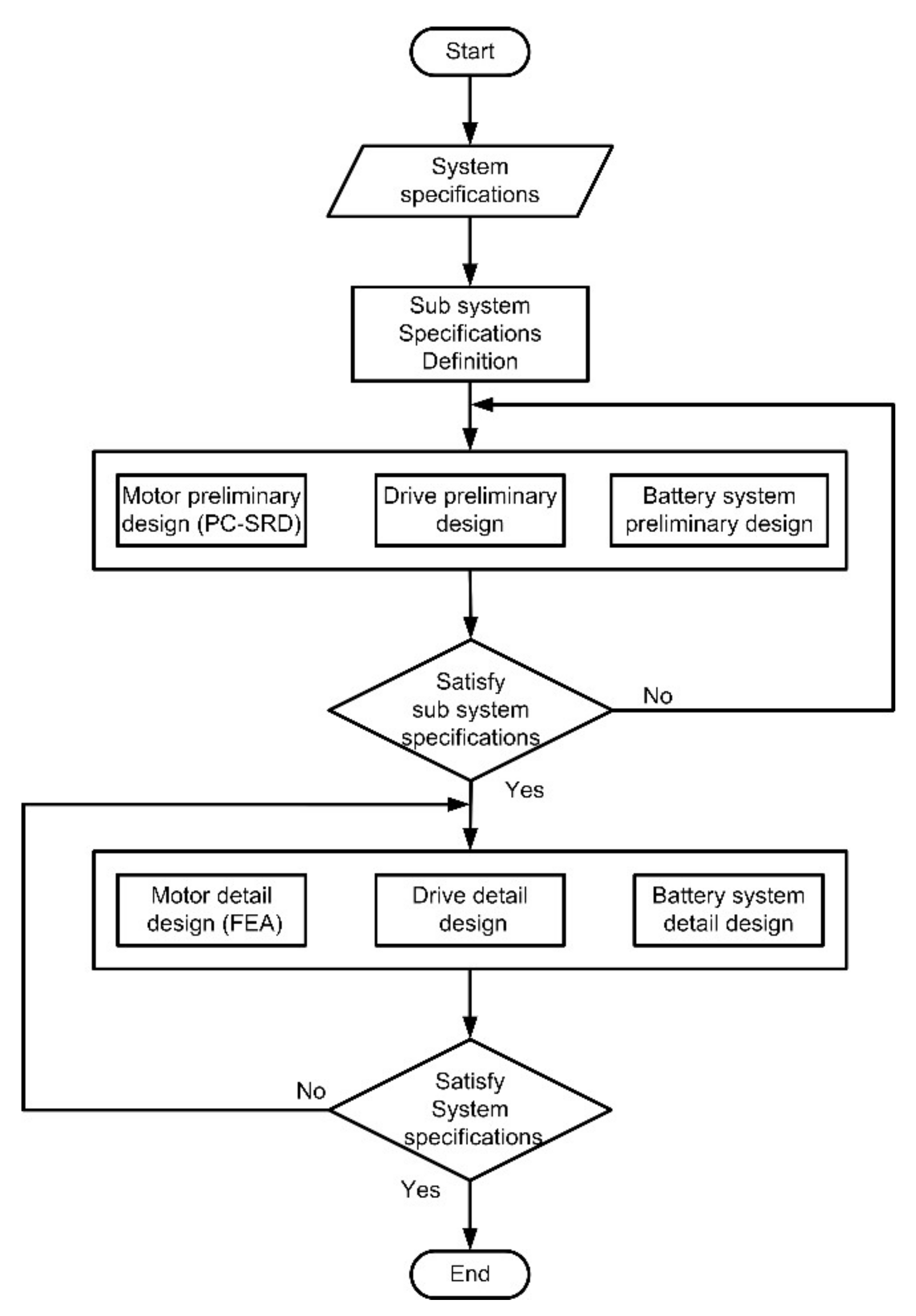
Figure 2 shows the overall electric motorcycle design process under consideration. The electric motorcycle specifications are cascading as subsequent targets for the following subsystem design. The specification of each subsystem, namely the traction motor, the motor drive system, battery system and mechanical structure, are taken into consideration since they have interactive impacts on the performance of the vehicle. Several iterative simulations have been conducted between system and subsystem levels in order to attain the desired design goals. These interactions include motor torque–speed characteristics, motor weight and size, DC voltage, battery DC current, drive and motor current, battery weight and size, and battery capacity. As the battery system is one of the key components in the electric motorcycle, the LiFePO4 battery pack has been chosen for its high capacity per weight ratio, size, and charge/discharge rate.

2.2. Traction Motor Design Consideration

The SRM was designed using a commercial analytical software package PC-SRD [16] and a 2D finite element analysis (FEA) using JMAG software. PC-SRD was used in the preliminary design phase to compare and adjust various design parameters, such as the number of stator/rotor poles, the number of phases, and the winding parameters. The software can calculate torque, current, efficiency, copper loss, iron loss, etc. It also includes a core structure, core material data, such as BH curves, iron loss curves, winding structure, applied voltage, rotational speed, and the on-off timing of an inverter. In order to gain high starting torque in the low-speed region, a four-phase 8/6 pole SRM and a three-phase 6/4 pole SRM were selected for performance comparison. Moreover, the weight and cost of the traction motor are also factors under consideration.
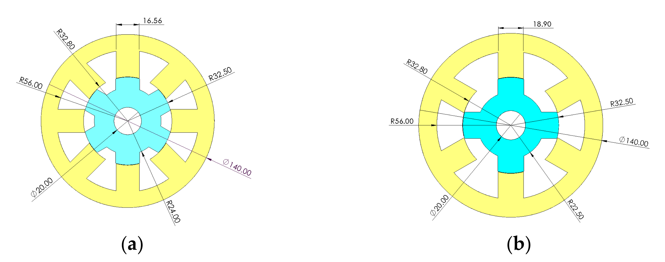
The design procedure of the switched reluctance machines starts with the selection of a frame size, which is performed in accordance with the existing standard of induction frame size (IEC71). The selection of frame size according to the IEC recommendations fixed the outer diameter of the stator and stack length in order to maintain a similar volume. According to the available space in the motorcycle, the key initial parameters included the stator’s outer diameter, which was fixed to 140 mm, and its stack length, which was fixed to 70 mm, as shown in Table 2.
Based on the guideline for selecting a suitable stator and rotor pole arc in [17,18], a stator pole arc at βs = 30 degrees and a rotor pole arc at βr = 31.5 degrees were selected as the initial parameters for the three-phase 6/4 pole SRM. Additionally, the air gap was set to 0.30 mm. The silicon steel with a thickness of 0.35 mm (35A300) was used and its BH curve was used for analysis in the simulation. The magnetic characteristics of iron cores are particularly important because SRMs do not use a permanent magnet. In this paper, the 35A300 in JIS, i.e., a general low-loss silicon steel, was used. This steel has a thickness of 0.35 mm and is equal to 36F168, 300, and V300-35A in AISI, BS, and DIN, respectively.
The torque performance in the low-speed region (2000 rpm) of the four-phase 8/6 pole and three-phase 6/4 pole SRMs was investigated for each combination of rotor yoke, stator yoke, rotor pole width, stator pole width, as well as the number of turns and number of strands, in order to satisfy the requirements presented in Table 1. Each parameter was varied under the same boundaries of maximum phase current, maximum current density, and flux density. Then, the maximum value of the developed torque was determined (optimal torque operation). The calculated outline geometry and winding parameters of both SRMs are shown in Figure 3 and Table 3. The preliminary results of both SRMs at 2000 rpm are shown in Table 4. It was found that both motors could generate torque larger than 8 Nm and the three-phase 6/4 pole SRM has a 13.2% larger torque and a 14.7% larger torque per weight than the four-phase 8/6 pole SRM. The total cost of the copper and iron of the three-phase 6/4 pole SRM is 6.5% more expensive, and its efficiency is 9.8% lower than the 8/6 pole SRM.

2.3. Static Performance Consideration

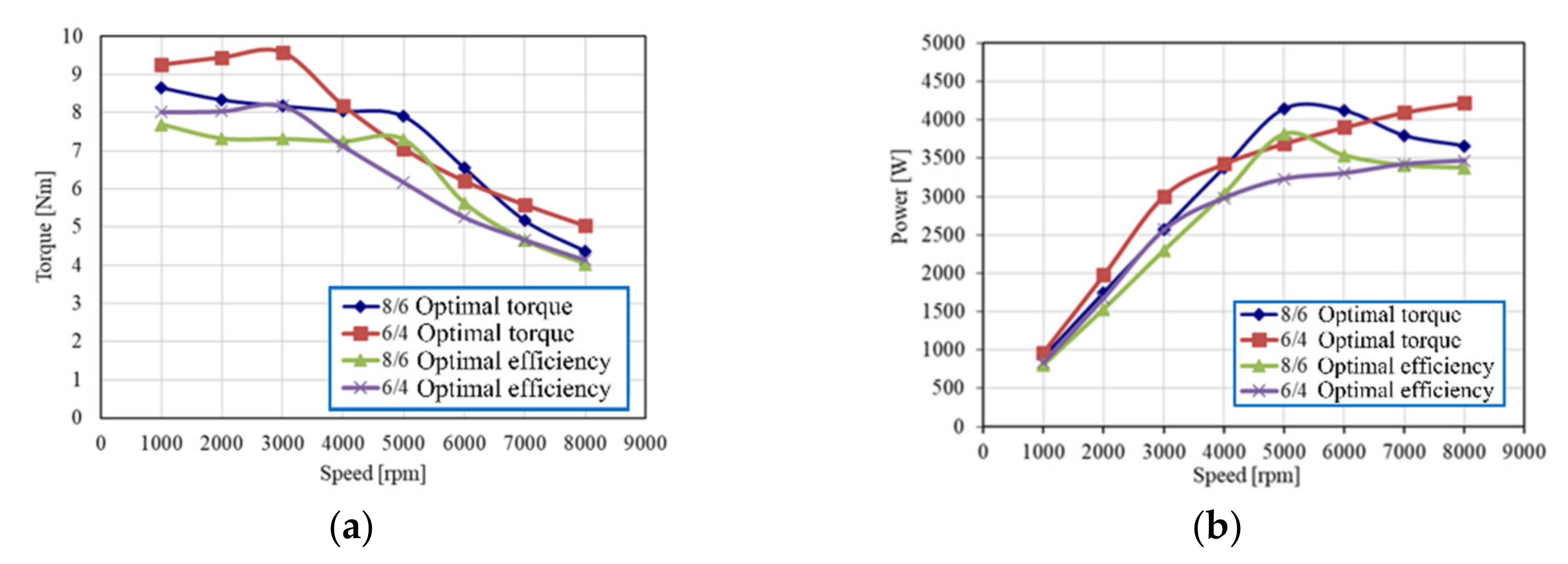
Figure 4 shows the torque, power, and efficiency characteristics of the designed four-phase 8/6 pole SRM and three-phase 6/4 pole SRM at each motor rotating speed. In the low-speed region, the motor is controlled by the current control mode, and it is controlled by voltage control in the high-speed region. At each operating speed, the turn-on and turn-off angles were adjusted under the same maximum value of the hysteresis band in order to search for the best combination value that serves either the optimal torque or optimal efficient operation. To find the best turn-on and turn-off control angles for the maximum torque and efficiency of the SRM, the grid search method, which is the easiest to implement for the small number of parameters, was applied to reach the optimal control angles. The optimization grid search method was implemented in Visual Basic for Applications (VBA) of Microsoft Excel, which can be linked to PC-SRD motor design software. Grid search was performed across different values of turn-on and turn-off angles. The different combinations of turn-on and turn-off angles are used as input for PC-SRD to evaluate and compare the torque and efficiency to find the optimal turn-on and turn-off angles.
Two objectives were defined for the optimization of this traction motor. The first objective is to search for the conduction angle that can give the highest torque at each speed. The second objective is to find the conduction angle that can achieve the highest efficiency at each speed. Constraints are that the torque of the second objective must be within the threshold level of 1.5 Nm of the required torque, maximum DC current is 120 A, and maximum DC voltage is 48 Vdc. Design variables are the turn-on angle (20–60 deg. for 6/4 SRM and 20–40 deg. for 8/6 SRM) and the turn-off angle (65–85 deg. for 6/4 SRM and 45–65 for 8/6 SRM). The objective function can be given in
O b j e c t i v e   F u n c t i o n = η + k t o r q u e   ·   T o r q u e
where η and k t o r q u e are the efficiency of the SRM and a factor which converts torque into an efficiency equivalent, respectively.
Equation (6) is maximized using a grid search optimization algorithm across the observed values of the threshold variable. Finally, the turn-on and turn-off angles for maximum torque and maximum efficiency at each speed (1000–8000 rpm) are obtained. For the optimal efficiency operation, the peak efficiency for the four-phase 8/6 pole SRM of about 91.13% at 6000 rpm can be achieved, which is not different from the peak efficiency for the three-phase 6/4 pole SRM of about 89.87% at 8000 rpm. Furthermore, for the optimal torque operation, in the low-speed region, the maximum average torque for the three-phase 6/4 pole SRM of about 9.57 Nm can be achieved, which is bigger than the maximum average torque for the four-phase 8/6 pole of about 8.66 Nm. That means the three-phase 6/4 pole SRM has better torque performance in the low-speed region and good efficiency performance in the high-speed region, which are preferable characteristics for electric motorcycle application.
The optimal angles for maximum torque were applied to control the vehicle during the low-speed regions or when a high dynamic response was required (braking and acceleration). The optimal angles for maximum efficiency were used to control the vehicle at medium to high-speed regions or at low torque requirements to increase the range of travel and reduce the power consumption of the battery.

2.4. Dynamic Performance Consideration

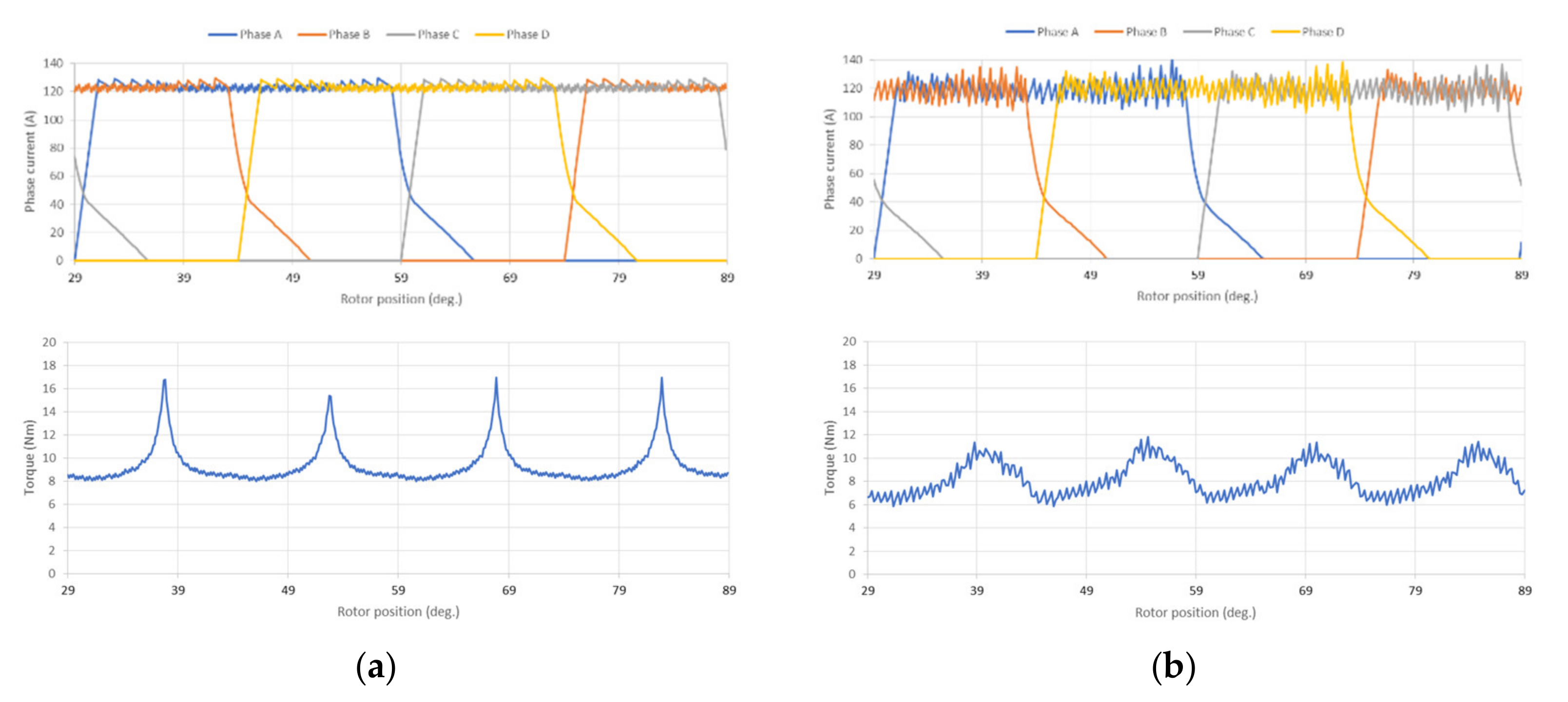
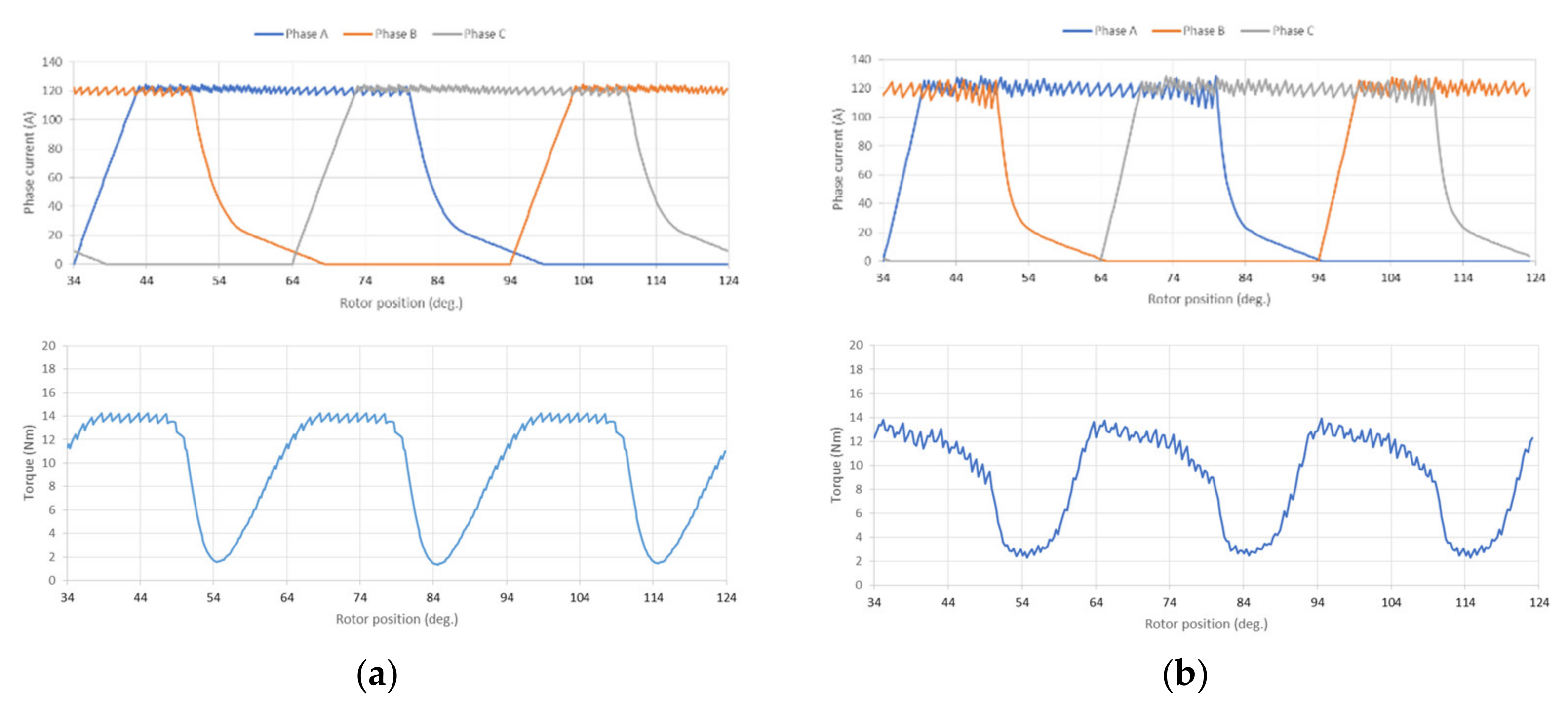
Basically, the three-phase 6/4 pole SRM has large torque ripple in the low-speed region. Therefore, it was necessary to observe the motor phase current and torque waveforms. The 2D FEA models for dynamic simulation are revealed in Figure 5. Figure 6 and Figure 7 show the dynamic simulation at 2000 rpm under the optimal torque operation calculated by PC-SRD and FEA for the four-phase 8/6 pole and three-phase 6/4 pole SRM, respectively. The calculated values of the average torque and torque ripple rate are shown in Table 5. According to the FEA calculation, some effects from the magnetic coupling between the phases could be clearly observed on the phase current and torque waveforms. The results calculated by FEA are smaller than the results calculated by PC-SRD. The three-phase 6/4 pole SRM has a larger torque ripple rate than the four-phase 8/6 pole SRM. The effect of torque ripple would be absorbed by the CVT gearbox. However, the three-phase 6/4 pole SRM also has a larger average torque. Therefore, the three-phase 6/4 pole SRM was selected and the final design verification was conducted. Afterwards, FEA was used to finalize the design before constructing the prototype as shown.
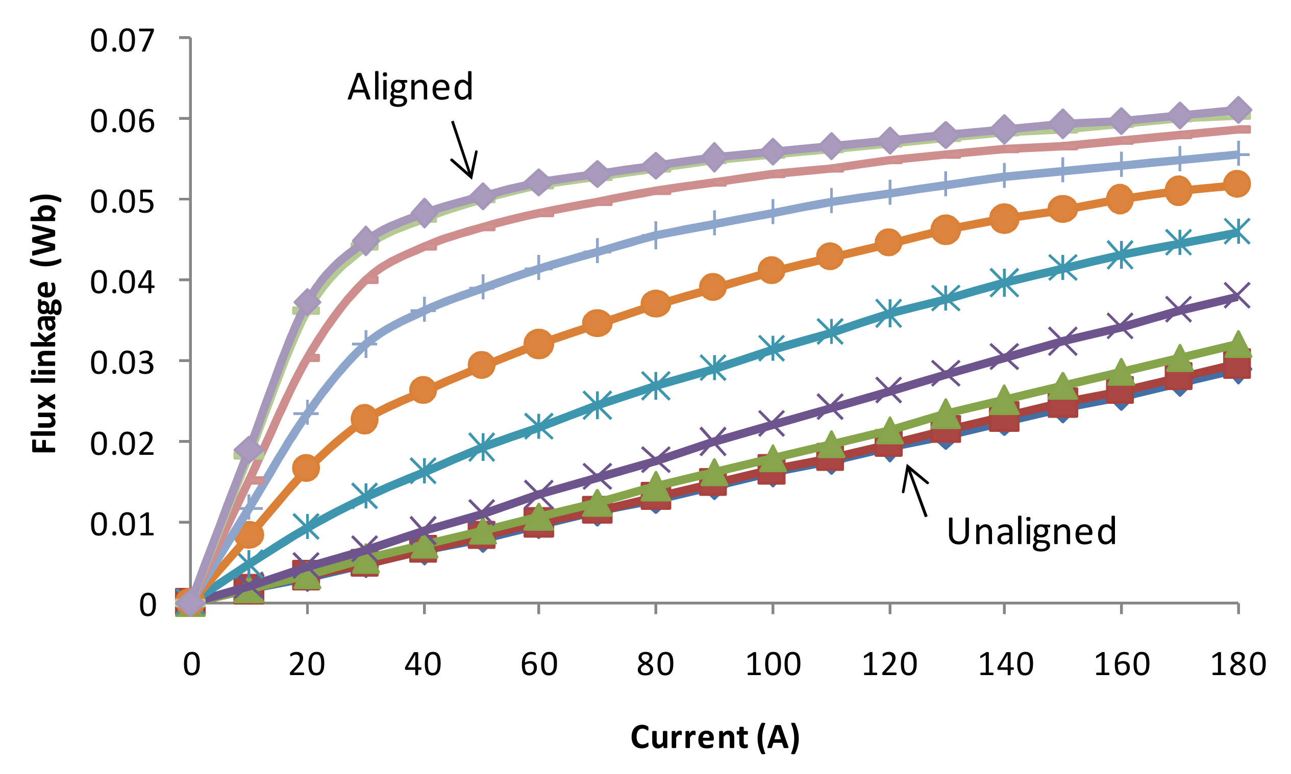
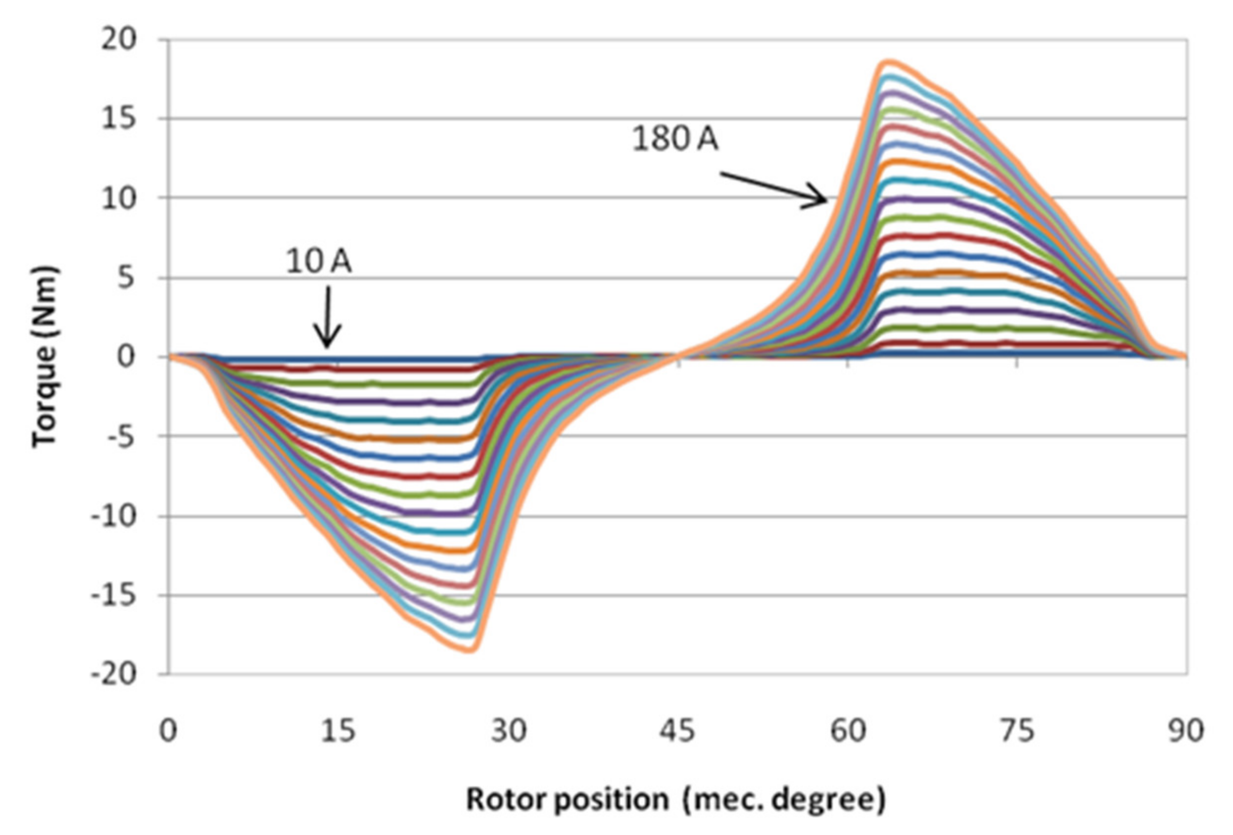
The result of the preliminary three-phase 6/4 pole SRM design was verified by FEA, which can compute the magnetic field distribution with a ferromagnetic material saturation effect within the structure of the SRM. The results indicate that the flux density levels are within the limit of the chosen 35A300 silicon steel material. The flux linkages of SRM at different current levels are shown in Figure 8, where the rotor position is varied from an unaligned to aligned position. The electromagnetic torque was calculated for various current levels where the maximum instantaneous torque of 18 Nm was achieved at 180 A, as shown in Figure 9.
Winding arrangement is another factor that could affect the static torque performance of the SRM. Figure 10 shows two winding configurations of the three-phase 6/4 pole SRM when a single phase (phase A) is excited with a unipolar operation. Figure 11 shows the flux density and flux path of the short-flux path and long-flux path winding configurations, respectively. The comparison of the static torque developed at each rotor position for both the short-flux and long-flux paths of the three-phase 6/4 pole SRM is based on the same conduction loss condition, which is also shown in Figure 12. The long-flux path winding could produce more positive torque during the effective torque production region, which is 45 mechanical degrees for the three-phase 6/4 pole SRM. The short-flux path winding could produce lower peak torque and it produces negative torque at 77–90 degrees. The three-phase 6/4 pole SRM should also be excited by bipolar excitation with a sinusoidal waveform [19] in order to reduce the torque ripple rate. However, the average torque and efficiency are also smaller than the unipolar excitation. Therefore, the static torque performance of the three-phase 6/4 pole SRM excited by bipolar excitation is not investigated here.

3. Construction of the Motor and Drive System

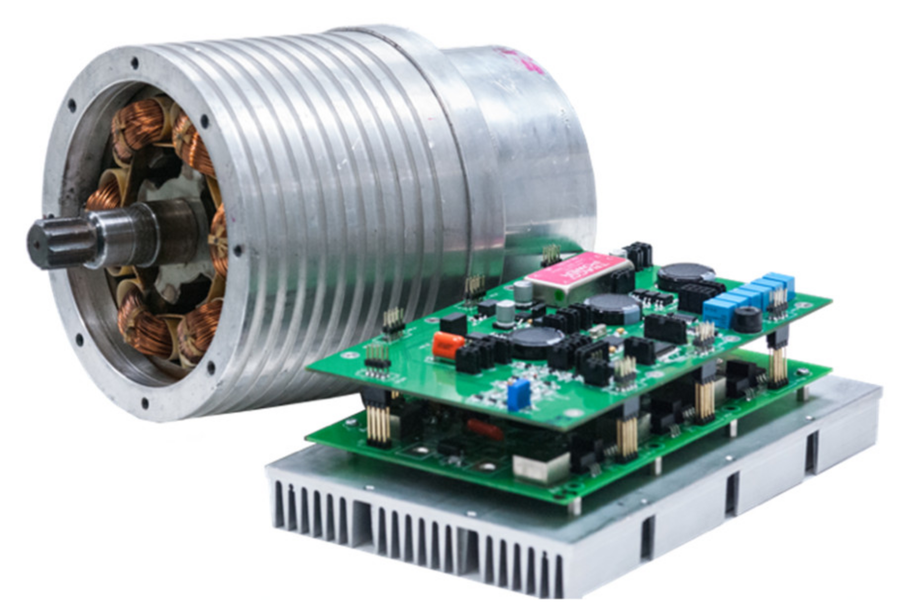
Figure 13 shows the constructed three-phase 6/4 pole SRM prototype and drive system. In total, 30 units of the three-phase 6/4 pole SRM were manufactured by the private company in order to control the quality of the prototypes.
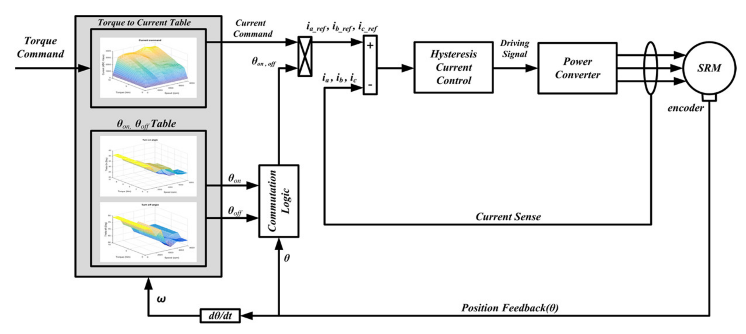
The motor drive system employs the conventional three-phase, asymmetric half-bridge inverter. This topology has the advantages of simplicity, robustness, and fault tolerance, where each phase can be controlled independently with unidirectional current flow. These greatly enhance the safety features of the electric motorcycle drive system. The control block diagram for the SRM drive system is shown in Figure 14, where the user turns the accelerator to define the torque command as an input. The motor torque is estimated based on the torque to current block. The optimal turn-on angle, turn-off angle, and current command for maximum efficiency operation (optimal efficiency operation) at each torque and speed level will be calculated off-line by FEA and put into the 3D look-up table, as shown in Figure 15. At each torque command and detected motor speed, the corresponding current command and on/off angles will be calculated by the following Equation.
f τ i , s i = s i s 2 s 1 s 2 τ i τ 2 τ 1 τ 2 f τ 1 , s 1 + τ i τ 1 τ 2 τ 1 f τ 2 , s 1 + s i s 1 s 2 s 1 τ i τ 2 τ 1 τ 2 f τ 1 , s 2 + τ i τ 1 τ 2 τ 1 f τ 2 , s 2
where τ i and s i are the torque command and detected motor speed, respectively.
The rotor position is also a necessary parameter for the indirect torque controller and current controller in the drive system. For the electric motorcycle application, especially when the vehicle with maximum payload starts from the standstill condition on the slope, the initial rotor position is very necessary for high starting torque development. Some low-cost, incremental optical encoders may be used for rotor position detection. However, they cannot detect the initial rotor position at a standstill condition, leading to torque jerk [20], which seriously affects the safety of the electric motorcycle. Furthermore, due to the harsh environment on the road, with dust, water, and vibration, a more reliable detection system for a non-contact rotor position is required. In this paper, the contactless magnetic-based position sensor was installed on the rotor shaft for position and speed feedback, as shown in Figure 16. It is a very low-cost and high-reliability solution. With the proposed mechanical coupling device using a bolted shaft and ball bearing, the effect of the deviated distance between the permanent magnet and sensing circuit caused by speed variation and vibration could be eliminated effectively. A resolution of the rotor position detection of about 0.87 degrees could be achieved from 0 to 8000 rpm. The proposed initial rotor position estimation method [20] based on pulse injection and phase current profile has a maximum error of about 2.5 degrees, but it could identify the sector of the rotor position. Therefore, the combination of the proposed rotor position estimation and magnetic sensing system could increase the reliability of the electric motorcycle.
The motor phase current is sensed by current sensor model ACS758ECB-200U which can be mounted on a PCB. The current regulation is also performed by an inner digital hysteresis controller. A 32-bit micro-controller, STM32F103RET6, and a power MOSFET, IRF4468, were used. Figure 17 shows the battery pack and circuit board in the battery management system. In one battery pack, a total of eight cells of LiFePO4 model NLC36130185PF (3.2 V 63 Ah) were connected in a series and two sets of battery packs were installed in each electric motorcycle. The voltage of each cell is monitored by the cell monitoring board and it is transmitted to the master board. The master board will perform passive balancing by bypassing the current to the cell that has the lower capacity and it will make a decision for communication to the quick charger and interlock circuit for safe operation.

4. Experiment Results

4.1. Motor and Drive System Test Result

The static test of the SRM prototype was conducted. The electrical characteristics of the prototype, such as the resistance and inductance, can be measured via a static test with the locked rotor. Table 6 shows the measured inductance and simulated value obtained from FEA. The small discrepancy may be caused by the effect of 2D FEA.
Figure 18 shows the efficiency map of the SRM prototype from the test results on the test bench. With the limited capacity of the testing equipment, the SRM drive was supplied with a 50 VDC voltage source and maximum DC current of about 100 A, which is less than the value used in the simulation. Therefore, performance of up to 7000 rpm was measured.
The maximum torque measured via a torque transducer was approximately 8.6 Nm at 3000 rpm. The motor has an efficiency of more than 80% at a high speed and medium torque output range (81.85% at 7000 rpm), which is very suitable for an electric motorcycle running at medium to high speed. This load condition is the most practical scenario for the normal usage of a general purpose electric motorcycle.

4.2. Electric Motorcycle Performance Test Result

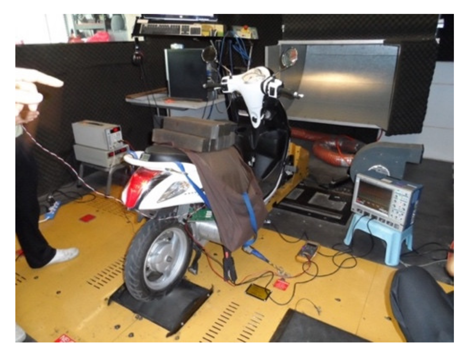
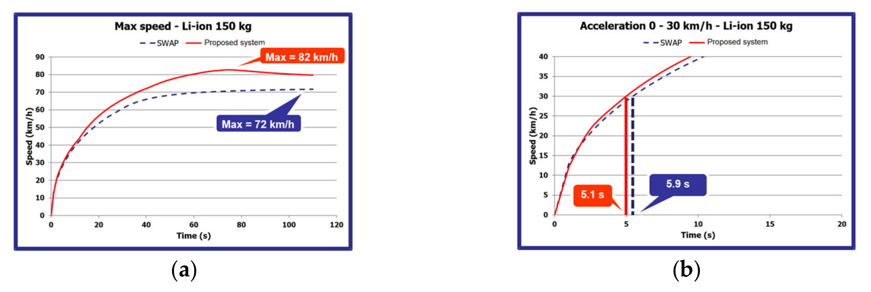
The performance of the constructed electric motorcycle was tested by a chassis dynamometer, as shown in Figure 19. The driving range of the electric motorcycle at a constant 40 km/h cruising speed (motor speed 4686 rpm) with a 150 kg pay load was measured. Figure 20 shows the measured values during the test run. From the starting time to 140 min, the measured current was about 30 A and the measured voltage gradually decreased from 51.20 V. When the running time reached 140 min, the battery voltage was lower than the battery threshold, and the drive system was then turned off. The total driving range of about 98 km could be achieved. The maximum vehicle speed and acceleration from 0 to 30 km/h during on-road testing with full payload (150 kg) were measured and compared to the commercial electric motorcycle, as shown in Figure 21. The maximum speed could reach 82 km/h and the acceleration time was about 5.1 s, which is better than the requirements in Table 1.
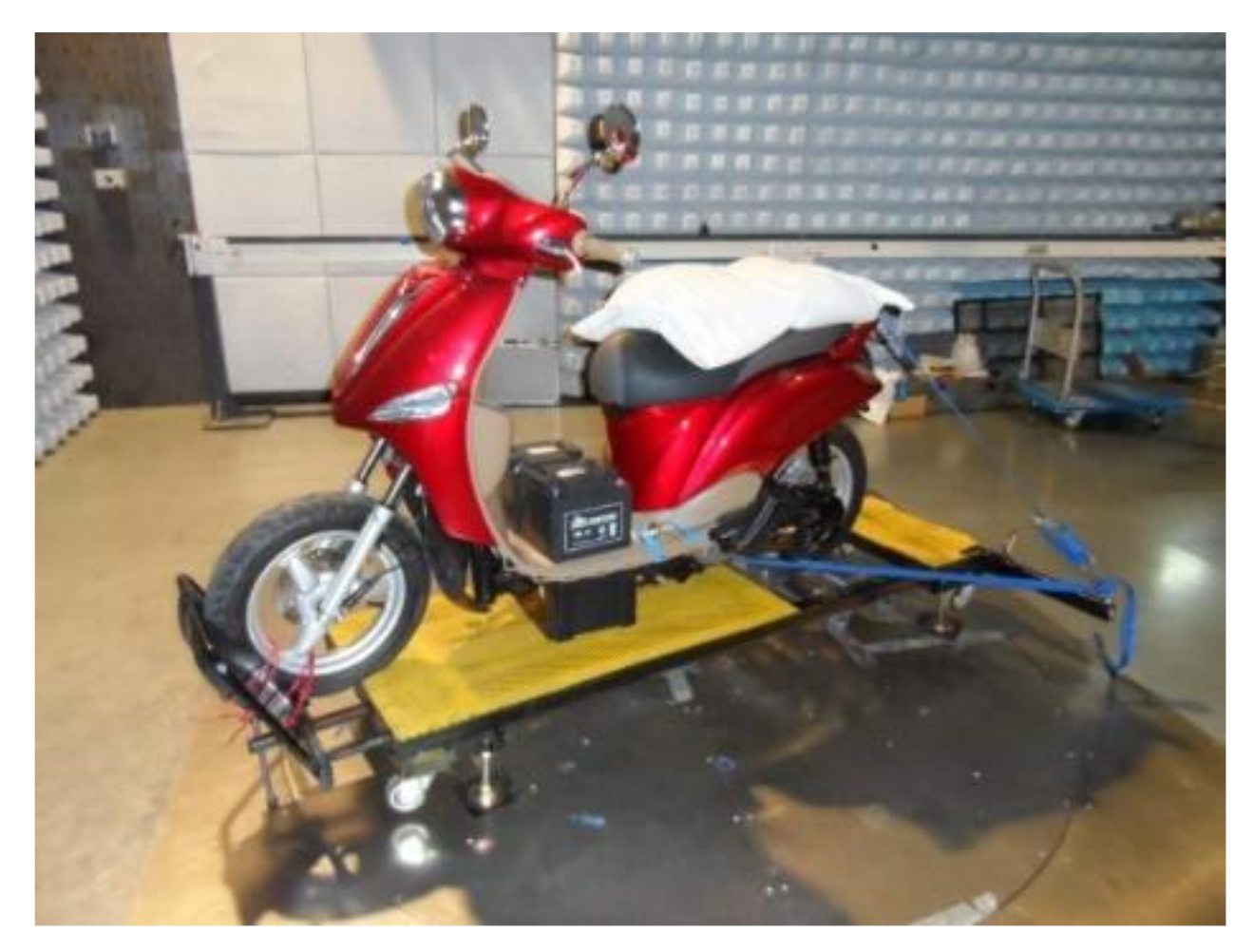
The constructed electric motorcycle was tested and complied with the electromagnetic compatibility standards, including radiated emission and immunity testing based on CISPR25:2002 and ISO 11452-2, respectively, as shown in Figure 22. Furthermore, the SRM drive system was also in compliance with the IEC1-60335 standard for the safety of household and similar electrical appliances. The SRM was also tested and complied with the IEC60529:2001 (IP56) standard. All 30 units of the completed electric motorcycles were produced and transferred to the Provincial Electricity Authority (PEA) for their internal routine services.

5. Conclusions

This paper described the performance improvement of an electric motorcycle driven by an SRM and drive system. The static performance comparison of the three-phase 6/4 pole and four-phase 8/6 pole SRM was undertaken. It was found that the three-phase 6/4 pole SRM had a larger starting torque and torque per weight in the low-speed region. In the high-speed region, both SRMs could reach about 90% with the optimal efficiency operation. The average and torque ripple rate of both SRMs were also investigated by dynamic simulation. The torque ripple rate of the three-phase 6/4 pole SRM was a bit larger than the four-phase 8/6 pole SRM. However, the three-phase 6/4 pole SRM also had a larger average torque. Therefore, the three-phase 6/4 pole SRM was also suitable for the propulsion system of the electric motorcycle. The performance of the three-phase 6/4 SRM was also investigated by FEA. The implementation of indirect torque control and rotor position detection in the drive system was proposed. According to the testing results obtained on the test bench, the highest motor efficiency of about 82% could be achieved. The vehicle performance, including a maximum speed of 82 km/h and a driving range of 98 km at a constant speed condition of 40 km/h, could be also achieved.

Author Contributions

Conceptualization, S.K., P.J., P.S., R.P. and K.T.; methodology, S.K., P.J., P.S. and K.T.; validation, R.P., S.K., P.J., P.S. and K.T.; formal analysis, S.K., P.J., P.S., R.P. and K.T.; investigation, R.P., P.S. and K.T.; resources, S.K., P.J. and P.S.; writing—original draft preparation, K.T.; writing—review and editing, R.P., S.K., P.J., P.S. and K.T.; visualization, R.P. and S.K.; supervision, P.S. and K.T. All authors have read and agreed to the published version of the manuscript.

Funding

This research was funded by the Provincial Electricity Authority Research Fund of Thailand.

Institutional Review Board Statement

Not applicable.

Informed Consent Statement

Not applicable.

Data Availability Statement

Not applicable.

Conflicts of Interest

The authors declare no conflict of interest.

References

  1. Kerdlap, P.; Gheewala, S.H. Electric motorcycles in Thailand—A life cycle perspective. J. Ind. Ecol. 2016, 20, 1399–1411. [Google Scholar] [CrossRef]
  2. Bostanci, E.; Moallem, M.; Parsapour, A.; Fahimi, B. Opportunities and challenges of switched reluctance motor drives for electric propulsion: A comparative study. IEEE Trans. Transp. Electrif. 2017, 3, 58–75. [Google Scholar] [CrossRef]
  3. Rahman, K.M.; Fahimi, B.; Suresh, G.; Rajarathnam, A.V.; Ehsani, M. Advantages of switched reluctance motor applications to EV and HEV: Design and control issues. IEEE Tran. Ind. Appl. 2000, 36, 111–121. [Google Scholar] [CrossRef]
  4. Lan, Y.; Benomar, Y.; Deepak, K.; Aksoz, A.; Baghdadi, M.; Bostanci, E.; Hegazy, O. Switched reluctance motors and drive systems for electric vehicle powertrains: State of the art analysis and future trends. Energies 2021, 14, 2079. [Google Scholar] [CrossRef]
  5. Jiang, J.W.; Bilgin, B.; Emadi, A. Three-phase 24/16 Switched Reluctance Machines for a Hybrid Electric Powertrain. IEEE Trans. Transp. Electrif. 2017, 3, 76–85. [Google Scholar] [CrossRef]
  6. Kiyota, K.; Chiba, A. Design of switched reluctance motor competitive to 60-kW IPMSM in third-generation hybrid electric vehicle. IEEE Trans. Ind. Appl. 2012, 48, 2303–2309. [Google Scholar] [CrossRef]
  7. Wang, S.; Zhan, Q.; Ma, Z.; Zhou, L. Implementation of a 50-kW four-phase switched reluctance motor drive system for hybrid electric vehicle. IEEE Trans. Magn. 2005, 41, 501–504. [Google Scholar] [CrossRef]
  8. Lin, J.; Schofield, N.; Emadi, A. External rotor 6-10 switched reluctance motor for an electric bicycle. IEEE Trans. Transp. Electrif. 2015, 1, 348–356. [Google Scholar] [CrossRef] [Green Version]
  9. Terzic, M.V.; Bilgin, B.; Emadi, A. Switched reluctance motor design for a forklift traction application. In Proceedings of the 2018 XIII International Conference on Electrical Machines (ICEM), Alexandroupoli, Greece, 3–6 September 2018; pp. 812–818. [Google Scholar]
  10. Andrada, P.; Blanque, B.; Capo, M.; Gross, G.; Montesinos, D. Switched reluctance motor for light electric vehicles. In Proceedings of the 2018 20th European Conference on Power Electronics and Applications (EPE’18 ECCE Europe), Riga, Latvia, 17–21 September 2018; pp. 1383–1388. [Google Scholar]
  11. Vosswinkel, M.; Lohner, A.; Platte, V.; Hirche, T. Design, production, and verification of a switched-reluctance wheel hub drive train for battery electric vehicles. World Electr. Veh. J. 2019, 10, 82. [Google Scholar] [CrossRef] [Green Version]
  12. Lin, C.H. Switched reluctance motor drive for electric motorcycle using HFNN controller. In Proceedings of the 2007 7th International Conference on Power Electronics and Drive Systems, Bangkok, Thailand, 27–30 November 2007; pp. 1383–1388. [Google Scholar]
  13. Tomczewski, K.; Wrobel, K.; Rataj, D.; Trzmiel, G. A switched reluctance motor drive controller based on an FPGA device with a complex PID regulator. Energies 2021, 14, 1423. [Google Scholar] [CrossRef]
  14. Anvari, B.; Toliyat, H.A.; Fahimi, B. Simultaneous optimization of geometric and firing angles for in-wheel switched reluctance motor drive. IEEE Trans. Transp. Electrif. 2018, 4, 322–329. [Google Scholar] [CrossRef]
  15. Ehsani, M.; Gao, Y.; Longo, S.; Ebrahimi, K.M. Modern Electric, Hybrid Electric, and Fuel Cell Vehicles Fundamentals, Theory, and Design, 2nd ed.; CRC Press: Boca Raton, FL, USA, 2010. [Google Scholar]
  16. SPEED Consortium University of Glasgow. User’s Manual: PC-SRD; Version 8.8, CD-Adapco; SPEED Consortium University of Glasgow: Glasgow, UK, 2011. [Google Scholar]
  17. Vijayraphavan, P. Design of Switched Reluctance Motors and Development of a Universal Controller for Switched Reluctance and Permanent Magnet Brushless DC Motor Drives. Ph.D. Thesis, Virginia Polytechnic Institute and State University, Blacksburg, VA, USA, 2001. [Google Scholar]
  18. Miller, T.J.E. Switched Reluctance Motors and Their Control; Magna Physics Publishing and Clarendon Press: Oxford, UK, 1993. [Google Scholar]
  19. Liu, X.; Zhu, Z.Q.; Hasegawa, M.; Pride, A.; Deodhar, R.; Maruyama, T.; Chen, Z. Performance comparison between unipolar and bipolar excitations in switched reluctance machine with sinusoidal and rectangular waveforms. In Proceedings of the 2011 IEEE Energy Conversion Congress and Exposition, Phoenix, AZ, USA, 17–22 September 2011; pp. 1590–1595. [Google Scholar] [CrossRef]
  20. Tungpimolrut, K.; Jitkreeyarn, P.; Kachapornkul, S.; Somsiri, P.; Chiba, A. Initial rotor position estimation of a SRM drive installed in an electric vehicle. IEEJ Trans. Electr. Electron. Eng. 2011, 6, 594–600. [Google Scholar] [CrossRef]
Figure 1. The electric motorcycle driven by the SRM and drive system. (a) The schematic of the electric motorcycle system; (b) the installed SRM and drive system.
Energies 15 00694 g001
Figure 2. The flowchart of the electric motorcycle design process.
Energies 15 00694 g002
Figure 3. Outline of the designed motor: (a) four-phase 8/6 pole SRM; (b) three-phase 6/4 pole SRM.
Energies 15 00694 g003
Figure 4. The simulated performance of the designed four-phase 8/6 and three-phase 6/4 SRM under optimal torque and optimal efficiency operations: (a) average torque versus rotating speed; (b) power versus rotating speed; (c) efficiency versus rotating speed.
Energies 15 00694 g004aEnergies 15 00694 g004b
Figure 5. Mesh size of FEA model (a) 6/4 SRM; (b) 8/6 SRM.
Energies 15 00694 g005
Figure 6. Four-phase current and total torque waveforms of the four-phase 8/6 pole SRM at 2000 rpm calculated from (a) PC-SRD; (b) FEA.
Energies 15 00694 g006
Figure 7. Three-phase current and total torque waveforms of the three-phase 6/4 pole SRM at 2000 rpm calculated from (a) PC-SRD; (b) FEA.
Energies 15 00694 g007
Figure 8. Flux linkage calculation from FEA.
Energies 15 00694 g008
Figure 9. Torque versus current and rotor position.
Energies 15 00694 g009
Figure 10. Winding configuration of the three-phase 6/4 pole SRM: (a) short-flux path; (b) long-flux path.
Energies 15 00694 g010
Figure 11. Flux distribution of each winding configuration: (a) short-flux path; (b) long-flux path.
Energies 15 00694 g011
Figure 12. Static phase torque for each winding configuration.
Energies 15 00694 g012
Figure 13. The prototypes of the three-phase 6/4 pole SRM and drive system.
Energies 15 00694 g013
Figure 14. The control block diagram.
Energies 15 00694 g014
Figure 15. Optimal value of (a) current command; (b) turn-on angle; and (c) turn-off angle at each torque command and motor speed level for optimal efficiency operation.
Energies 15 00694 g015
Figure 16. Rotor position detection system: (a) mechanical coupling device; (b) a constructed rotor position detection system installed on the three-phase 6/4 pole SRM.
Energies 15 00694 g016
Figure 17. (a) Lithium ion battery pack; (b) master board of the battery management system; (c) cell monitoring board of the battery management system.
Energies 15 00694 g017
Figure 18. Efficiency map of the constructed three-phase 6/4 pole SRM.
Energies 15 00694 g018
Figure 19. Test run of the constructed electric motorcycle on a chassis dynamometer.
Energies 15 00694 g019
Figure 20. (a) Measured DC voltage and distance; (b) measured DC current and vehicle speed.
Energies 15 00694 g020
Figure 21. (a) Maximum vehicle speed; (b) acceleration from 0 to 30 km/h.
Energies 15 00694 g021
Figure 22. EMI/EMC testing of the constructed electric motorcycle.
Energies 15 00694 g022
Table 1. Targeted specification of the electric motorcycle.
ParameterUnit1 Passenger2 Passenger
Maximum speedkm/h8070
Acceleration 0–30 km/hs46
Driving Range at 40 km/hkm9080
Payloadkg75150
Table 2. Key initial parameters of each motor.
ParameterUnit8/6 Pole SRM6/4 Pole SRM
Rated motor voltage (DC)V4848
Outer stator dimensionmm140140
Stack lengthmm7070
Air gapmm0.30.3
Table 3. Calculated parameter of each motor.
ParameterUnit8/6 Pole SRM6/4 Pole SRM
Radius to the bottom of the rotor slot (R0)mm2422.5
Rotor surface radius (R1)mm32.532.5
Radius to the bottom of the stator slot (R2)mm5656
Stator outside radius (R3)mm7070
Air gapmm0.30.3
Stator pole arc (βs)deg22.524
Rotor pole arc (βr)deg2031.05
Number of turns-916
Number of strands-1111
Wire diametermm0.9140.813
Material-35A30035A300
Rotor inertiakg*·m24.8777 × 10−45.1453 × 10⁻⁴
Table 4. Preliminary result of the four-phase 8/6 pole and three-phase 6/4 pole SRM at 2000 rpm.
ParameterUnit8/6 Pole SRM6/4 Pole SRM
Phase resistanceOhm0.0120.032
Aligned inductancemH0.5462.065
Unaligned inductancemH0.0620.264
Theta ondeg2934
Theta offdeg5880
Average torqueNm8.349.44
Phase current (rms)A85.6282.8
Shaft powerW1746.371976.89
Overall system efficiency%80.4673.27
Copper lossW362659
Iron lossW5553
Mechanical lossW68
Flux density at rotor poleT2.1791.723
Flux density at stator poleT1.9222.197
Copper weightkg1.33051.5959
Iron weightkg5.31654.9165
Torque per weightNm/kg1.251.44
Total copper and iron cost$52.7556.19
Table 5. Calculated average torque and torque ripple rate of each motor.
8/6 Pole SRM6/4 Pole SRM
PC-SRDFEAPC-SRDFEA
Average torque (Nm)8.348.239.449.15
Torque ripple rate0.960.721.331.27
Table 6. Measured inductance value compared to FEA.
PhaseL-Aligned (mH)L-Unaligned (mH)L-Ratio
A1.97670.29606.6774
B1.80160.33425.3904
C1.93850.28646.7666
FEA2.06520.26437.8150
Publisher’s Note: MDPI stays neutral with regard to jurisdictional claims in published maps and institutional affiliations.