Article

Detent Force Minimization of Double-Sided Permanent Magnet Linear Synchronous Machine with 120° Phase Belt Toroidal Windings by Slot-Shift Structure

1
School of Electrical Engineering, Zhengzhou University, Zhengzhou 450001, China
2
Department of Electronic Engineering, University of York, York YO10 5DD, UK
3
Zhengzhou Runhua Intelligent Equipment Co., Ltd., Zhengzhou 450004, China
*
Author to whom correspondence should be addressed.
Energies 2022, 15(3), 943; https://doi.org/10.3390/en15030943
Submission received: 22 November 2021 / Revised: 5 January 2022 / Accepted: 21 January 2022 / Published: 27 January 2022

Abstract

:
Double-sided permanent magnet linear synchronous machine with 120° phase belt toroidal windings (120°-TWDSPMLSM) suffers from large detent force due to the end effect and slot effect. Many existing methods can reduce the detent force of the 120°-TWDSPMLSM effectively. But they also minimize the back electromotive force (back-EMF) and thrust simultaneously. To alleviate this problem, this paper adopts a method of combining slot-shift structure with rearranging the 120° phase belt toroidal windings (120°-TW) to suppress the detent force and improve the back-EMF and thrust of the 120°-TWDSPMLSM simultaneously. First, the slots on the two sides of the primary part are stagger by an optimal distance to reduce the detent force. The models of the detent force, including the end force and cogging force, is established theoretically, and then verified by finite-element analysis (FA). Then, the 120°-TW are rearranged to improve the back-EMF and average thrust. And the electromagnetic characteristics of the 120°-TWDSPMLSM under different shifted distances are analyzed and compared in detail. Finally, the result shows that the detent force of optimized machine is 70.19% lower than that of the original machine, and the thrust fluctuation reduces 19.21%. Besides, the back-EMF of optimized machine is 6.84% lower than that of the original machine, but 31.86 higher than the machine with shifting slots and without rearranging the 120°-TW. Therefore, the optimal method in this paper is available in the detent force reduction and thrust improvement of the 120°-DSPMLSM.

1. Introduction

The double-sided permanent magnet linear synchronous machine (DSPMLSM) is widely used in various industrial applications and daily life, such as material and express handling and transportation, owing to the simple structure, high thrust density, low maintenance cost, and unilateral magnetic force [1,2,3,4]. Unfortunately, it suffers from large detent force which includes the end force owing to the longitudinal end effect and cogging force due to slot effect of the DSPMLSM. The detent force could cause undesirable mechanical vibration and noise, which makes the machine work difficultly, especially under the condition of low speed. Therefore, it is of great significance to suppress the detent force of the DSPMLSM.
Researchers have done. Much excellent work to reduce the detent force effectively, and these approaches can be classified into two types. One type for the reduction of the detent force is to adopt control methods. Refs. [5,6] used a direct compensation current method and a simple feed-forward current compensation approach to reduce the detent force, respectively. The method of combination skewed permanent magnets design with discretization control is adopted to eliminate the detent force [7]. But, this method is mainly related to complex algorithms and controllers and not considered in this paper. The other type for the reduction of the detent force is to optimize the structure of the machine, including secondary [8,9,10] and primary parts [11,12,13,14,15,16,17]. For example, several methods including chamfering, skewing, and magnet pole shifting were applied for detent force reduction [8]. The analysis results in ref. [9] showed that the staking length of both ends of the step could be reduced to get lower detent force. Ref. [10] adopted the method of unequal pole-arc coefficients of edge and middle magnets and suppressed the detent force effectively. A novel technique using auxiliary poles was presented and had a good effect on the reduction of detent force [11]. The detent force ref. [12] could be reduced by a suitable primary length and the smooth formed edge of the primary. Optimizing the primary length and applying step-skewed auxiliary iron could minimize the detent force [13]. Ref. [14] adopted auxiliary teeth method to reduce the detent force effectively. The detent force can be suppressing by the modular primary structure [15]. All of the methods have made significant contribution to the reduction of the detent force.
In addition to the above methods, refs. [16,17], the detent force can be offset by shifting the secondary components to a certain distance. Similarly, staggering the teeth which are set on the two sides of one the primary component can achieve similar results. However, the shifted methods cause the reduction of the back-EMF and thrust.
In order to solve the problem, Huang et al. proposed shifting one of the primary components by a certain distance, which could decrease detent force effectively in a DSPMLSM [18] and improve the thrust by changing the winding arrangements of the distributed and short-pitch windings. However, the distributed and short-pitch windings are employed, which result the first five and the last five slots in each side being half-filled. The problem can be solved by adopting the concentration windings or toroidal winding. In ref. [19], the back-EMF of DSPMLSM with the toroidal winding is higher than that of DSPMLSM with the concentration windings under the same condition. Therefore, this paper adopts the 120°-TW, which the incoming ends of all coils are on the same side and have the same incoming direction. Because the winding arrangement of toroidal winding has been rarely studied after slot-shift structure in literature. This paper adopts a method of combining slot-shift primary structure with rearranging the 120°-TW to suppress the detent force and improve the back-EMF and thrust of the DSPMLSM with 120°-TW (120°-TWDSPMLSM) simultaneously.
The rest of this paper is organized as follows. In Section 2, the structure of the 120°-TWDSPMLSM is introduced and the detent force is analyzed. Besides, the slot-shift structure is described. Section 3 establishes its end force model to analyze the influences of the shifted distance on the end force. In Section 4, the model of the cogging force is established theoretically and verified by back electromotive force (back-EMF) analysis. Section 5 analyzes the influences of the shifted distance on the detent force. In Section 6, the windings are arranged differently to improve the average thrust. The back-EMF and characteristics of the windings are analyzed and compared, and the thrust and efficiency of the DSPMLSM with different shifted distances are compared. Finally, conclusions are drawn in Section 7.

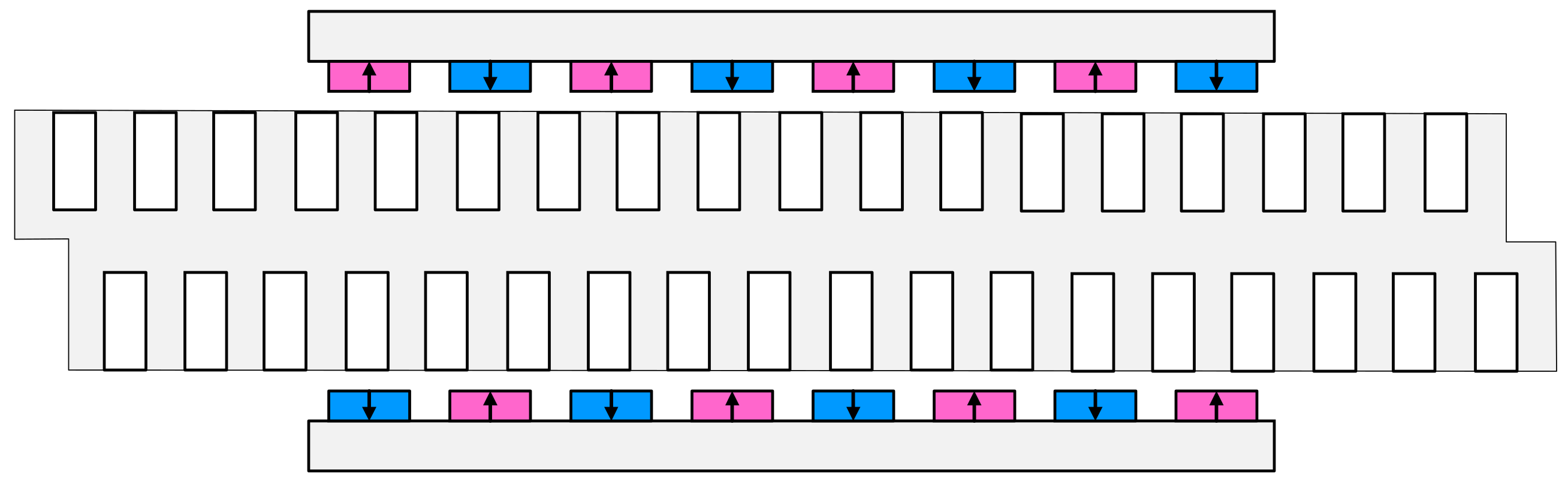
2. Structure and Detent Force of 120°-TWDSPMLSM

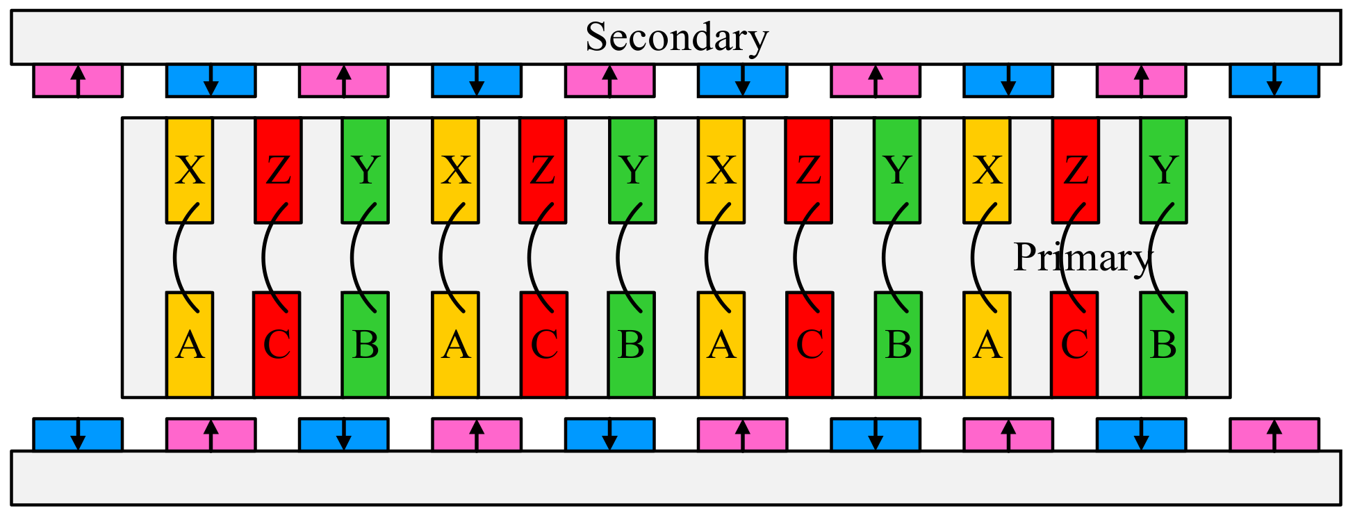
2.1. Structure of 120°-TWDSPMLSM

The structure sketch of the 120°-TWDSPMLSM is depicted in Figure 1, which includes of one primary (mover) and two secondary (stator) parts. The primary consists of the 120°-TW and primary iron. The permanent magnets are arranged alternately along the moving direction on the surfaces of the secondary yokes, forming the secondary parts. The primary part is located in the middle of the two secondary parts.
Besides, it should be noted that the incoming line ends of the 120°-TW are on the same side and have the same incoming direction. Moreover, the magnetic flux lines are close through the secondary yoke, the air gap, the primary teeth, and the primary yoke, forming the parallel magnetic circuits. The geometrical parameters of the DSPMLSM are listed in Table 1 [19].

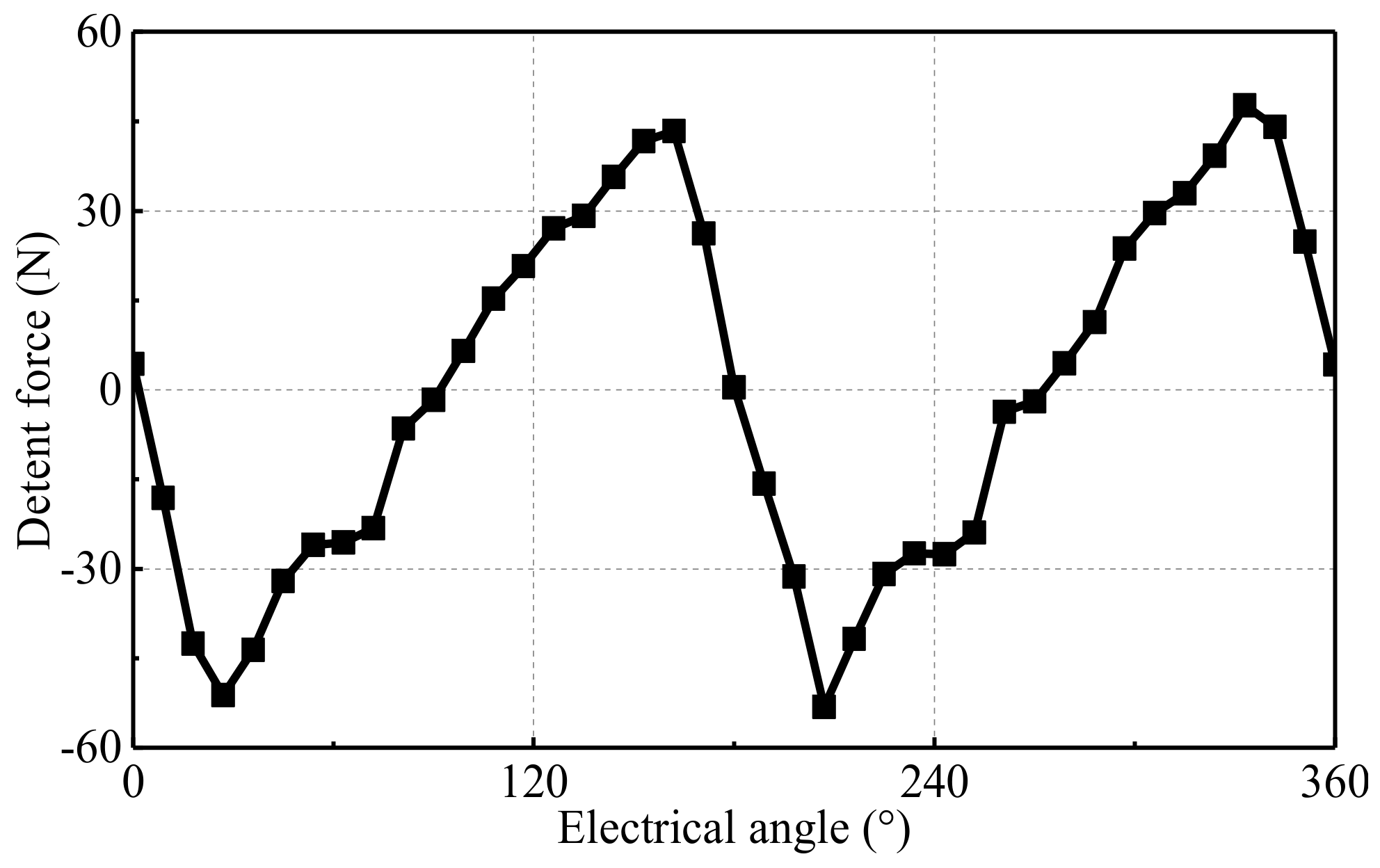
2.2. Detent Force of 120°-TWDSPMLSM

Based to Table 1 and software MagNet, the finite element model of the 120°-TWDSPMLSM is established. The boundary conditions of the machine are set. The solution is Newton–Raphson iteration method, the iteration tolerance is 1%, and the time step is 5 ms. Self-adaptive mesh refine is adopted, and the maximum element size of the mesh is set to 2 mm. The air-gap is divided into two-layer and the maximum element size of the mesh is set to 0.2 mm. The finite-element model of the 120°-TWDSPMLSM is shown in Figure 2.
Figure 3 shows the waveform of detent force. Its peak-to-peak value is 100.84 N. The large detent force has an influence on the characteristics of the machine. Therefore, the detent force is expected to be as small as possible.

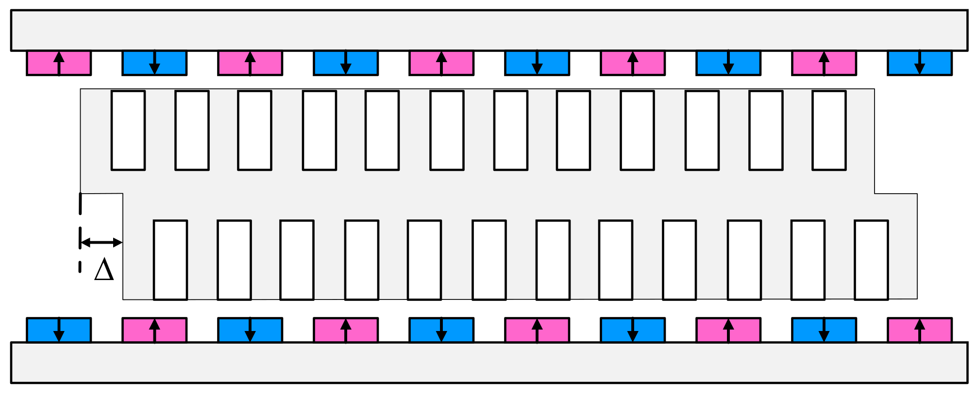
2.3. Slot-Shift Structure of 120°-TWDSPMLSM

The slot-shift structure of the 120°-TWDSPMLSM is shown in Figure 4. In order to clearly illustrate the analysis, the primary part is considered to consist of the upper and lower primaries. The upper (or lower) primary is made up of the upper (or lower) slots, teeth, and yoke. The lower primary shifts Δ to the right [18].
Δ = S τ
where S is the shift-distance coefficient, which ranges from 0 to 1. τ is the pole pitch.

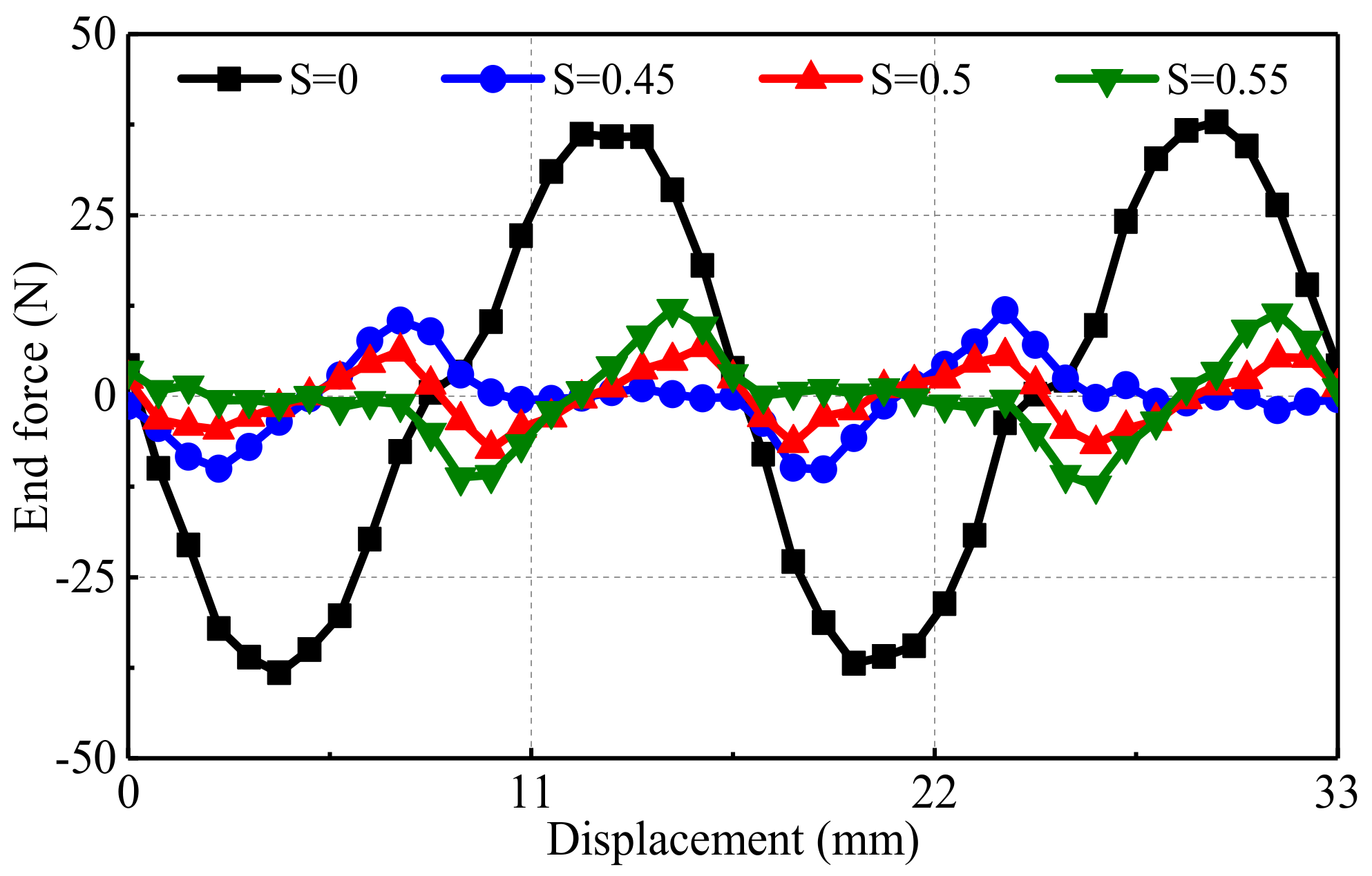
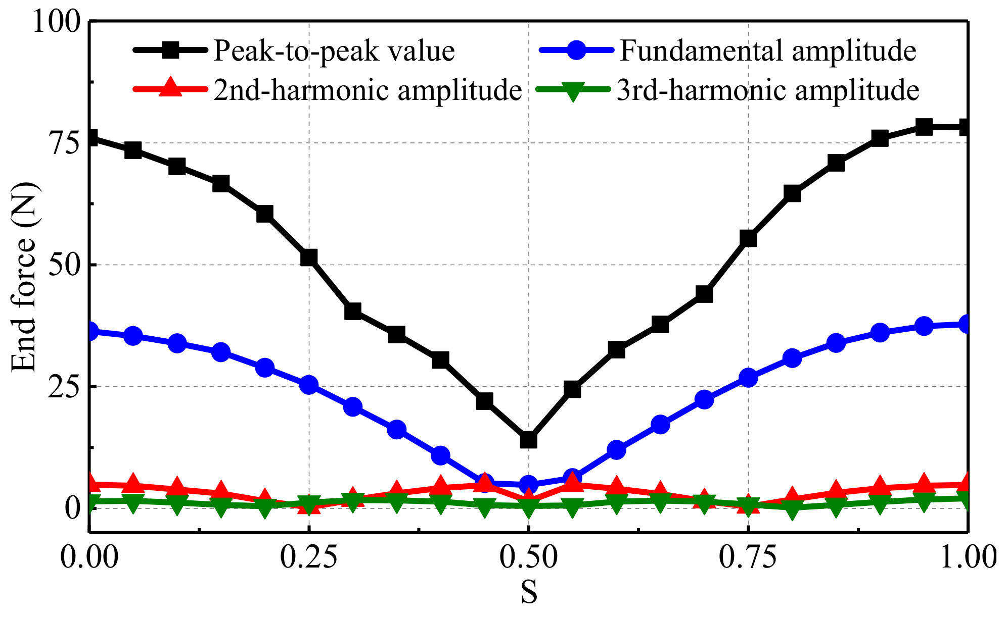
3. Analysis of End Force

3.1. Theoretical Analysis of End Force

The end forces of upper and lower primaries can be shown in Formulas (2) and (3) [20].
f e n d _ u p ( x ) = n = 1 F n 1 sin 2 n π τ ( x + L m τ 2 )
f e n d _ l o w ( x ) = n = 1 F n 2 sin 2 n π τ ( x + τ + L m τ 2 + Δ )
where fend_up(x) and fend_low(x) are, respectively, the end force of the upper and lower primaries, Fn1 and Fn2 are, respectively, the amplitudes of n-th harmonics of the fend_up(x) and fend_low(x), x is the relative position between the secondary and primary components, m is an integer, and L is the length of the primary.
If the magnetic coupling effect between the upper and lower primaries is not taken into account, the end force of the entire machine is equal to the sum of end force of upper and lower primaries. Since the lengths and structure of the upper and lower primaries are same, the amplitude of the Fn1 and Fn2 are identical, namely Fn1 = Fn2 = Fn. Therefore, the end force of the whole DSPMLSM fend is shown in Formulas (4) and (5) [21].
f e n d ( x ) = f e n d _ u p ( x ) + f e n d _ l o w ( x ) = n = 1 F d n sin 2 n π τ x + φ n
F d n = F n 1 + cos τ 1 + S 2 + sin τ 1 + S 2 = K d F n
where Fdn is the amplitudes of the n-th harmonics of the fend.
It can be seen from formulas (5) that the amplitudes of the entire end force harmonic change with S. The variation can be observed by the coefficient Kd. If S ranges from 0 and 1/2, the fundamental amplitude decreases with the increase of S. If S ranges from 1/2 and 1, the fundamental amplitude increases with the increase of S. When S is equal to 1, the fundamental amplitude of the end force of the entire primary is twice of the single upper (or lower) primary.

3.2. Simulation and Verification of End Force

In order to eliminate the slot effect and analyze the influence of the slot-shift structure on the longitudinal end effect. The slot-less FEM is established, as shown in Figure 5. In this case, the detent force is equal to the end force. The influence of the shifted distance S on the end force is shown in Figure 6. When S = 0, the peak-to-peak value of the end force is approximately equal to 76.05 N, and the ripple period of the end force is τ. This is consistent with the theory presented. When S = 0.5, the peak-to-peak value of the end force is reduced greatly to 14.06 N, which is 81.51% lower than that of S = 0.
Figure 7 shows the peak-to-peak values and the amplitudes of the fundamental, 2nd, and 3rd harmonics of the end force vary with the shifted distance coefficient S. It can be seen that the peak-to-peak values and the amplitudes of the fundamental of the end force reduce with the increase of the S, when S ranges from 0 to 0.5. On the contrary, which increase with the increase of the S, when S ranges from 0.5 to 1. Besides, the fundamental amplitudes are much larger than the higher-order harmonics. When S ranges from 0.45 to 0.55, the fundamental amplitudes have relatively smaller values. Especially, when S is about 0.5, the fundamental amplitude is the smallest, about 4.80 N.
The machine can obtain the smallest end force when S is 0.5. Besides, it can be found from Figure 7 that the peak-to-peak values of the end force when S changes from 0 to 0.45 are lower than those when S ranges from 0.55 to 1. It indicates that when the value of S increases to be larger than 0.5, the influence of the magnetic coupling can be negligible. In a world, the magnetic coupling between the upper and the lower primary laminations contributes to the reduction of the end force.

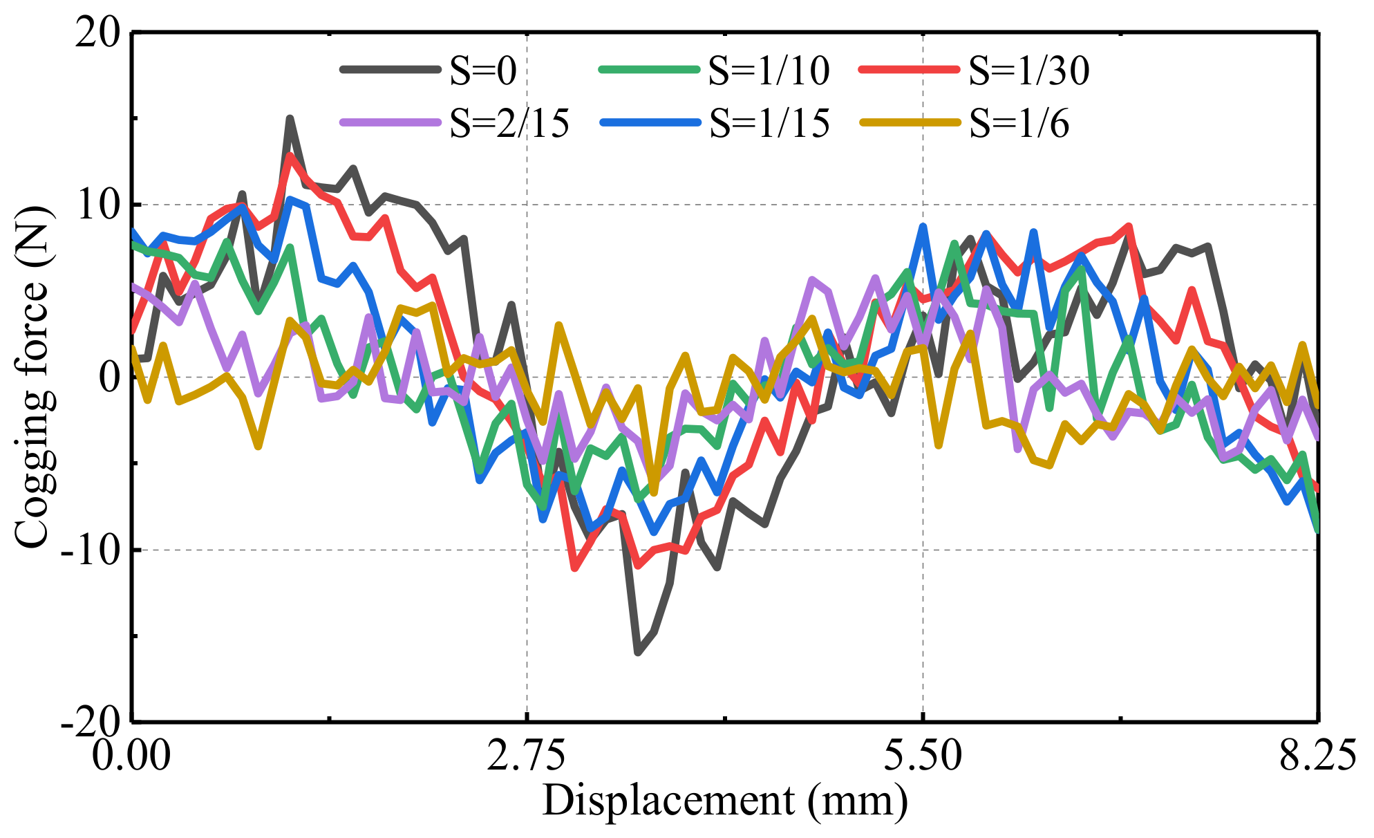
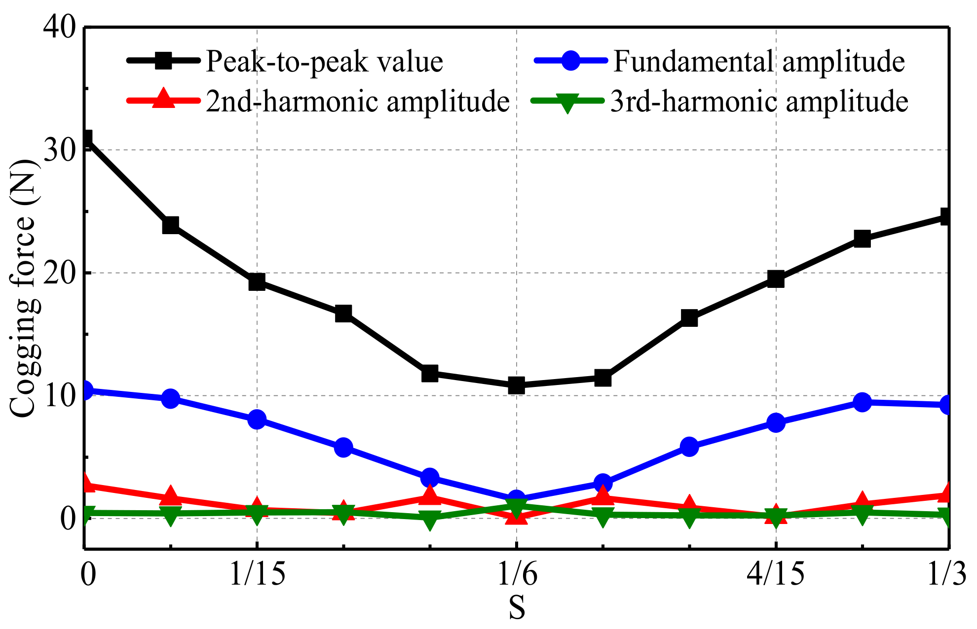
4. Analysis of Cogging Force

4.1. Theoretical Analysis of Cogging Force

The cogging forces of upper and lower until machines, which can be expressed as Fourier series, are shown in Formulas (6) and (7) [22].
f c o g _ u p = j = 0 P 1 k = 1 F k , j sin ( k 2 π x τ s + φ k , j )
f c o g _ l o w = j = 0 P 1 k = 1 F k , j sin ( k 2 π ( x + τ + S · τ ) τ s + φ k , j )
where fcog_up and fcog_low are respectively the cogging force of the upper and lower unit machine, P, Fk,j and φk,j denote the pole number, the amplitude of the k-th harmonic, and the initial phase angle of the k-th harmonic, which is generated by the j-th pole, respectively.
If the initial phase angle of the first pole’s cogging force is 0°, φk,j can be shown in Formula (8) [18].
φ k , j = j 2 π q p
where qp is the slot number of each pole.
Therefore, the entire cogging force is shown in Formulas (9) and (10) [18].
f c o g = f c o g _ u p + f c o g _ l o w = j = 0 P 1 k = 1 F k , j K k sin ( k 2 π x + τ + S τ τ s + φ k , j + φ k , j )
K k = 2 + 2 cos k 2 π τ / τ s 1 + S
The values of the phase angle φ′k,j and φk,j are the same, and the value of φ′k,j is associated with the harmonic order k.
The amplitude of the entire cogging force changes with S, which can be obtained by analyzing the values of Kk. The theoretical analysis results show that when S is equal to (k1/2 + 1/4) τs (k1 can be any integer), the cogging force value is minimum.

4.2. Simulation and Verification of Cogging Force

As shown in Figure 8, the EFM is established to verify the cogging force characteristics described above. The primary is longer than the two secondary parts. The length of the secondary is kept 132 mm, which is also the coupling length of the primary and the secondary of the DSPMLSM. The main difference is that the end effect of the long-primary machine is much less than that of the short-primary machine. Therefore, the cogging force which is calculated by the model in Figure 8. Considering the influence of the secondary ends, all distances which are between the primary ends and the secondary ends should be set to be larger than 3τ. In this case, there is very little pulsating magnetic field produced in the air gap by the longitudinal end-effect, and the end force is close to 0 N. Thus, the detent force is approximatively equal to the cogging force.
Figure 9 shows the calculated cogging forces with different shifted-distance coefficient S. All the cogging forces ripple with the period of half one slot pitch τs. When the S is 0, the amplitude of the cogging force is the largest. As the S increases from 0 to τ/3 (corresponding to 0 to τs/2), the amplitude of the cogging force reduces from 30.92 N down to 10.82 N.
Figure 10 shows the peak-to-peak values and the amplitudes of the fundamental, 2nd, and 3rd harmonics of the cogging force vary with the shifted distance coefficient S. The fundamental-amplitude curve varies with S and the variable period is 1/3, that corresponds to a half slot pitch. When the S is (2k2 + 1)/6 (where k2 can be any integer), the fundamental amplitude is the smallest.

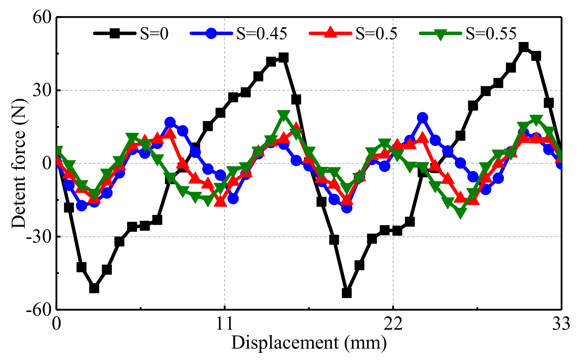
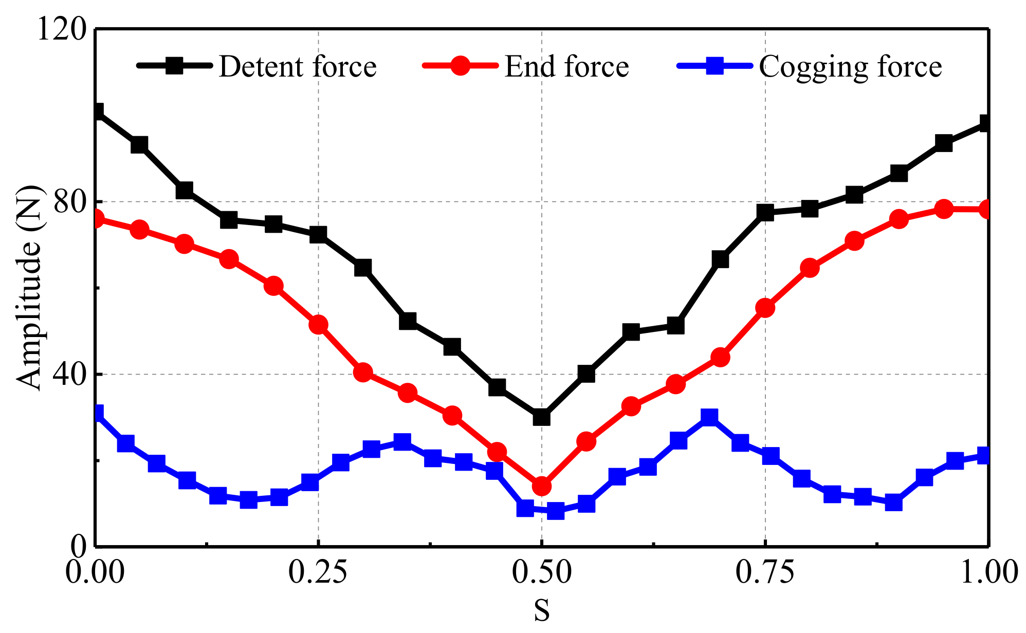
5. Simulation of Detent Force

The detent force is equivalent to the sum of the end force and cogging force. The FEM of the whole DSPMLSM is established, and the detent forces with different S as shown in Figure 11. It should be seen that the period of the detent force when S is designed as 0.5 is half of that of the coefficient S is 0.
The amplitudes of the detent forces, end forces and cogging forces, which are calculated by different coefficient S described previously, are compared in Figure 12. It can be seen that the end force is much larger than the cogging force. Thus, the end force has a great influence on the detent force. Additionally, the period of the end force is three times that the cogging force. Besides, the end force is lower than the detent force. It means that the slot structure strengthens the end effect.
In a period that S varies from 0 to 1, when S is 0.5, the amplitudes of the detent force, end force, and cogging force achieve a minimum value. The detent force (30.06 N) when S is designed as 0.5 is 70.19% lower than that (100.84 N) when the coefficient S is 0.

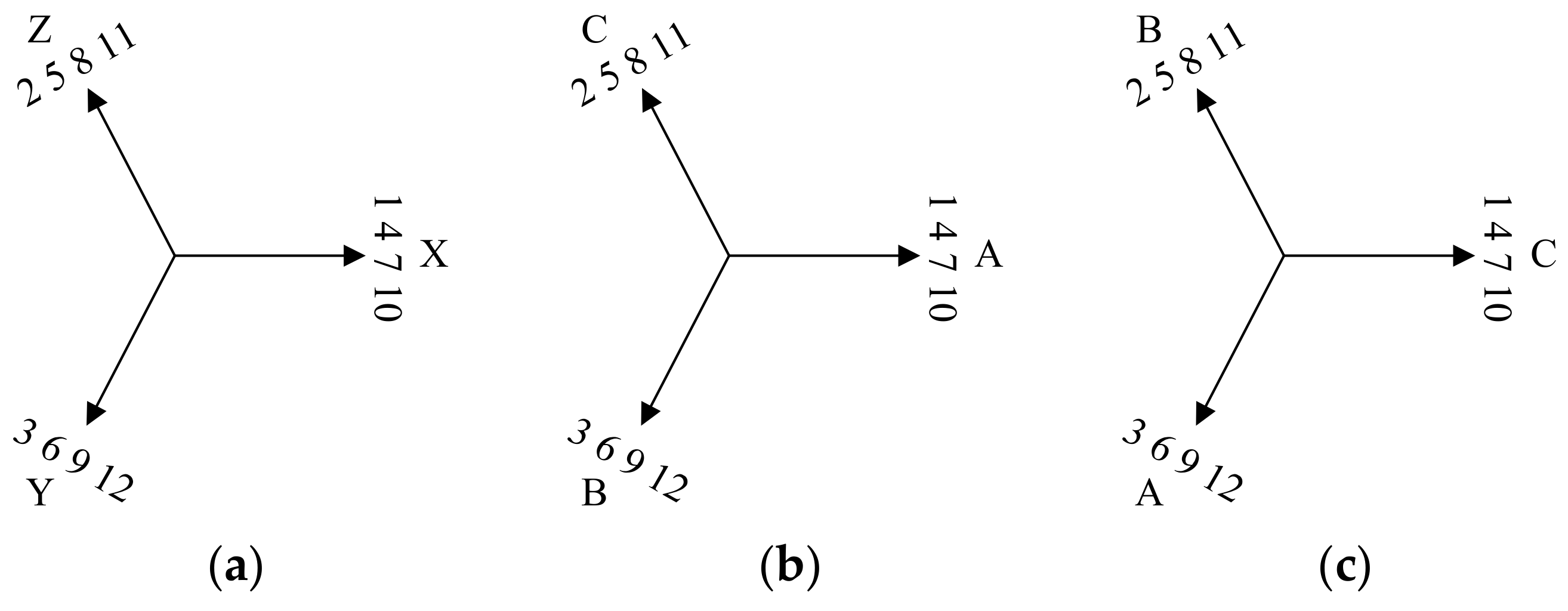
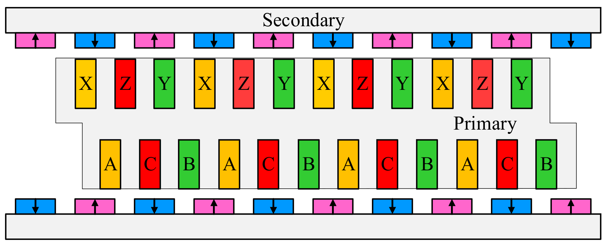
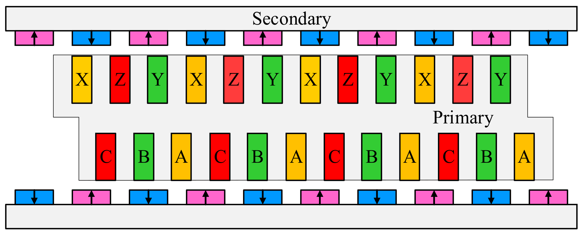
6. Winding Arrangements and Characteristic Analysis

6.1. Arrangement of 120°-TW

In order to facilitate the analysis of winding arrangement, the incoming line ends (A, B and C) and outcoming line ends (X, Y and C) of the 120°-TW are considered as the lower conductors and upper conductors, respectively. The upper primary is not shifted and the conductor arrangement is shown in Figure 13a. Since the lower primary is shifted by a certain distance with respect to the upper primary, there is a spatial electrical angle difference between the lower conductors and upper conductor of the 120°-TW. When S is designed as 0.5, the corresponding spatial electrical-angle difference is 90°, if the conductor arrangement does not change (shown in Figure 13b), the back-EMF of the machine shown in Figure 14 will inevitably decrease, comparing with the non-shifted 120°-DSPMLSM. This phenomenon will result in the decrease of the thrust. Therefore, in order to reduce the difference, the slot electrical potential star vectogram of lower conductors should be rotated by the same angle. However, since the electrical angle of each slot is 120°, the rotating angle must be an integral multiple of 120°. And 120° is the reasonable value, as shown in Figure 13c. And the winding arrangement is shown in Figure 15.

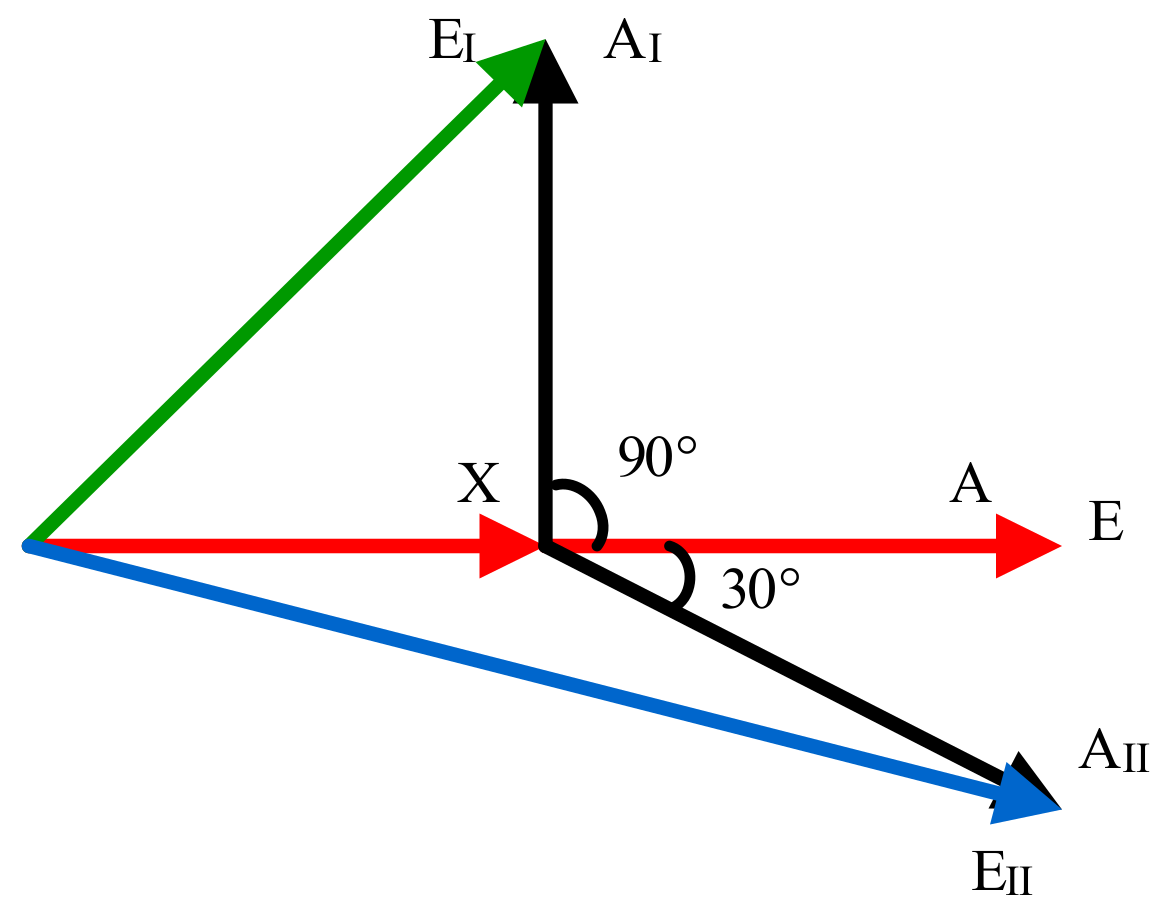
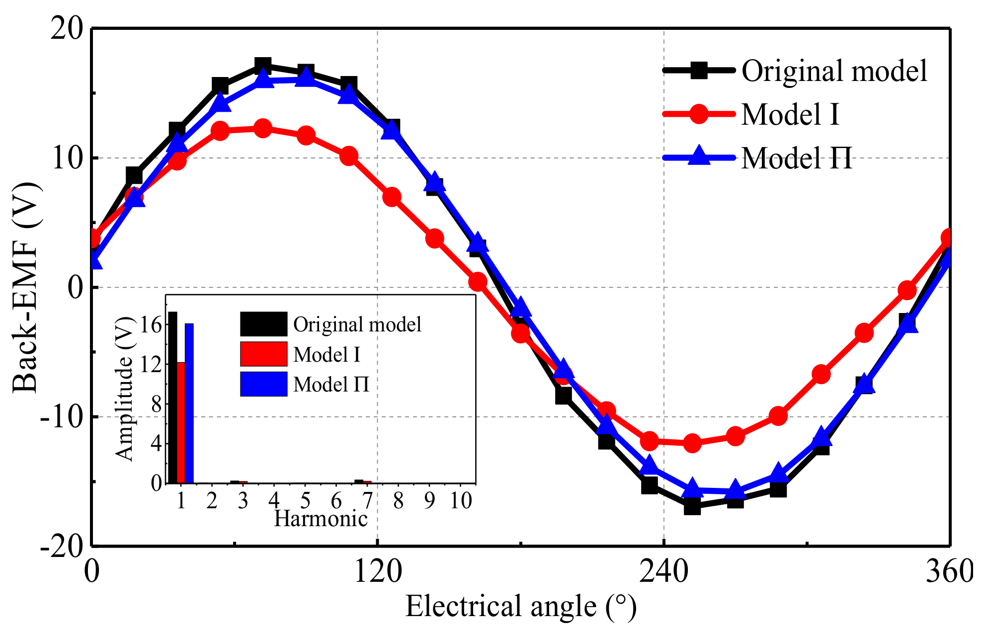
6.2. Back-EMF Characteristic

The single-phase vector diagram of synthetic electromotive force of the slot-shift DSPMLSM with 1/4 model is shown in Figure 16. The red line E denotes the synthetic electromotive force, which is the sum of the red lines (X and A) of the non-shifted DSPMLSM. When the lower primary is shifted by 90° (A) and the 120°-TW arrangements are kept identical, the green line E expresses the sum of the A and X. It could be calculated that the amplitude of E is 29.29% lower than that of E. When the lower primary is shifted 90° and the 120°-TW is rotated by 120° (A), the blue line E is the synthetic electromotive force, which is the sum of the A and X. It could be calculated that the amplitude of E is 3.50% lower than that of E, but 36.06% higher than that of E.
To verify the above analysis of the back-EFM, the EMF model is established. When the moving speed of the mover is 0.33 m/s, the back-EMF curves of the three machines are shown in Figure 17. For the DSPMLSM with S = 0.5, the back-EMF amplitude of Model Ⅰ (12.18 V) is 29.35% lower than that of the original model (17.24 V), and the back-EMF amplitude of Model Ⅱ (16.06 V) is 6.84% lower than that of the original model. However, the back-EMF amplitude of Model Ⅱ is 31.86% higher than that of Model Ⅰ. The simulation results are basically consistent well with the previous analysis. Therefore, by changing the winding arrangement, the back-EMF of Model Ⅱ has more advantages comparing with Model Ⅰ.

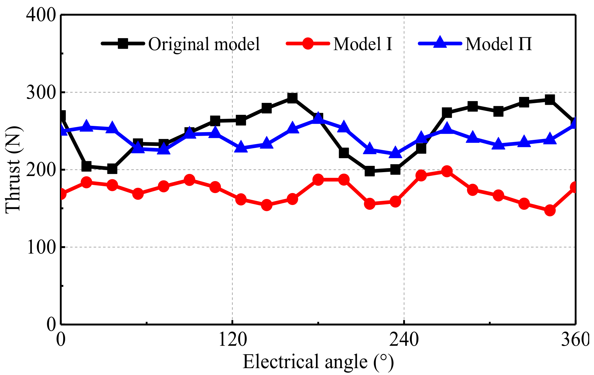
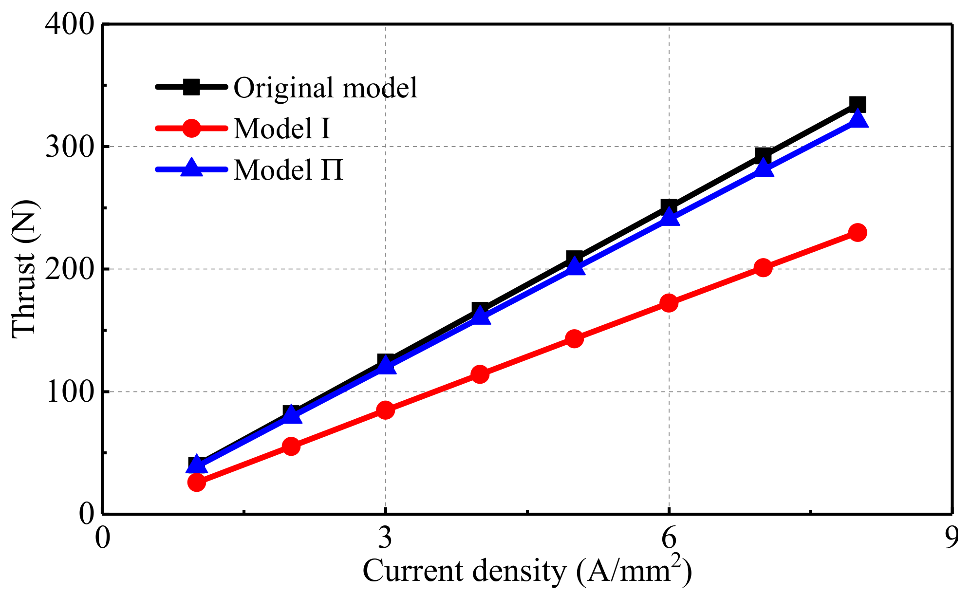
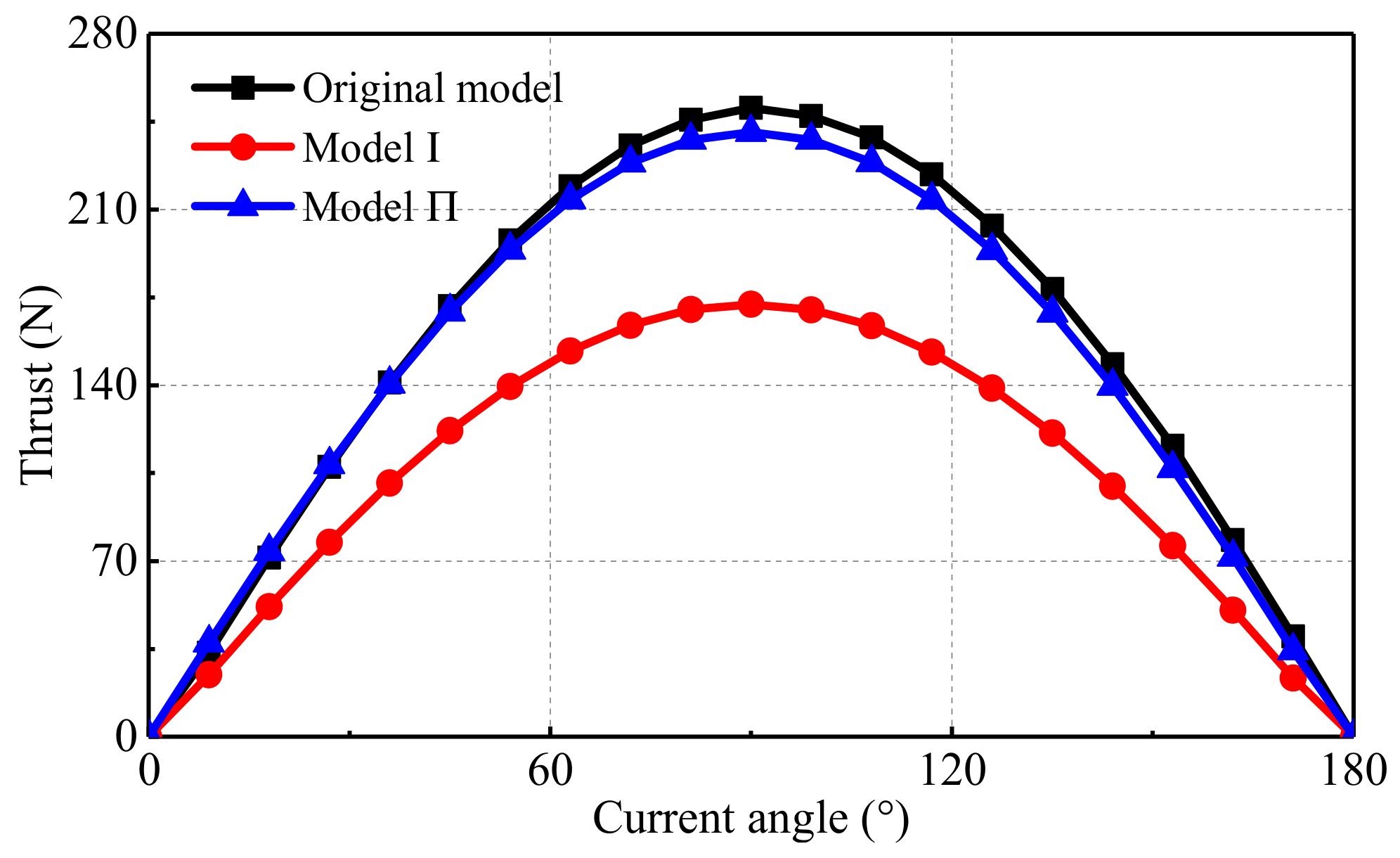
6.3. Thrust Characteristic

Figure 18 shows the thrust waveforms of the three machines on the approximately magnetic and electrical load. It can be seen that the average thrust of the original model, Model Ⅰ and Model Ⅱ are 250.40 N, 172.21 N and 240.71 N, respectively. Additionally, the thrust density of Model Ⅱ is 3.87% lower than that of the original model but is 39.78% higher than that of Model Ⅰ. Besides, thrust ripples of the original model, Model Ⅰ and Model Ⅱ are 37.60%, 29.27% and 18.39%, respectively. This indicates the thrust of Model Ⅱ is significantly improved comparing with Model Ⅰ, by adjusting the winding arrangement. Besides, the thrust fluctuation of Model Ⅱ is reduced to 18.39% comparing with the original machine.
The waveforms of the thrust versus current density in the three machines are shown in Figure 19. The average thrust of Model Ⅱ is lower than that of the original model, but higher than that of Model Ⅰ in various frequencies. Besides, the average thrust of the three machines all increase linearly with the increase of the armature current density.
The waveforms of the thrust versus armature current angle at the same current density of the three machines are shown in Figure 20. It can be seen that the three machines reach the maximum thrust when the current angles of the three machines are all 90°.

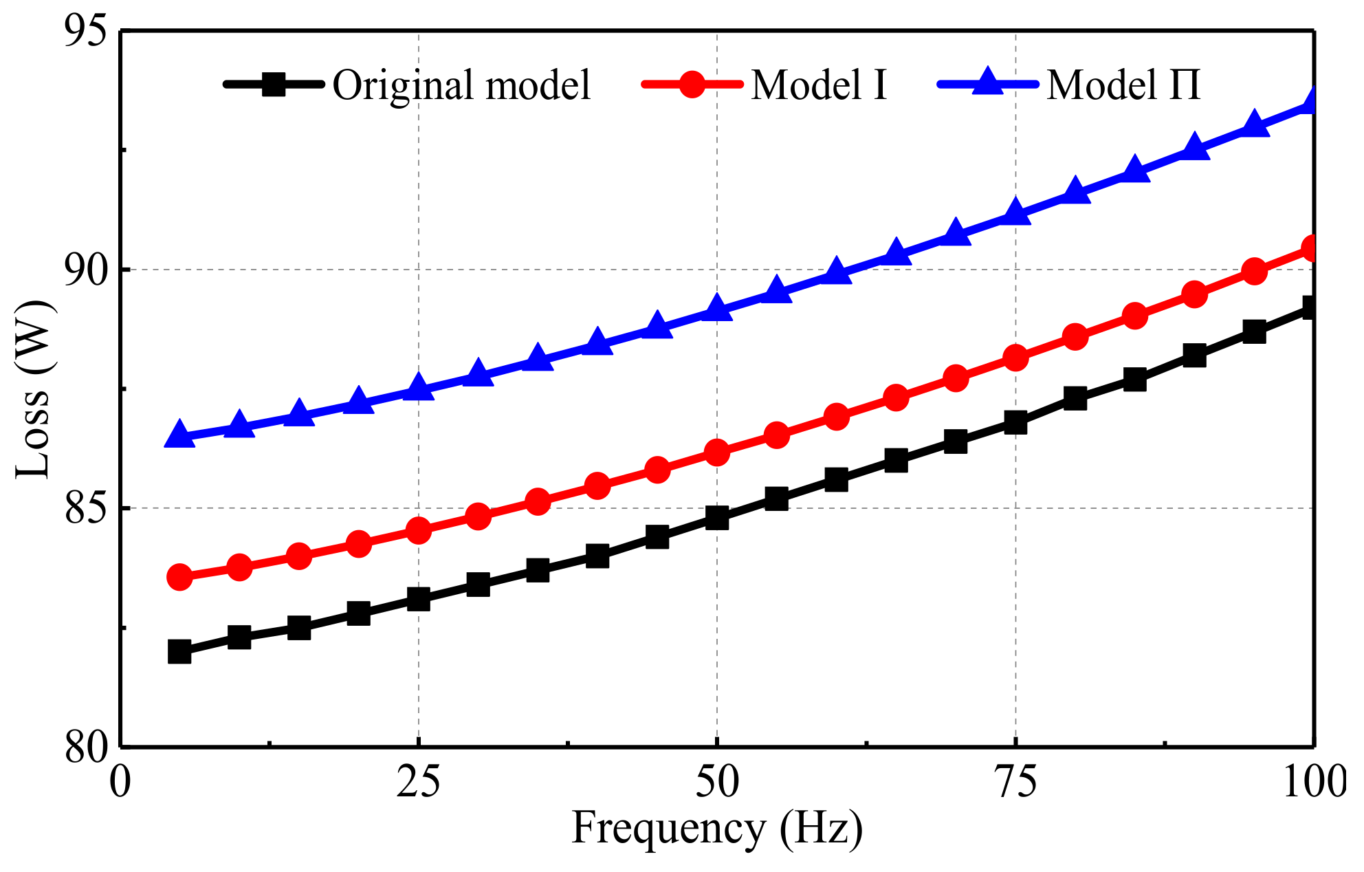
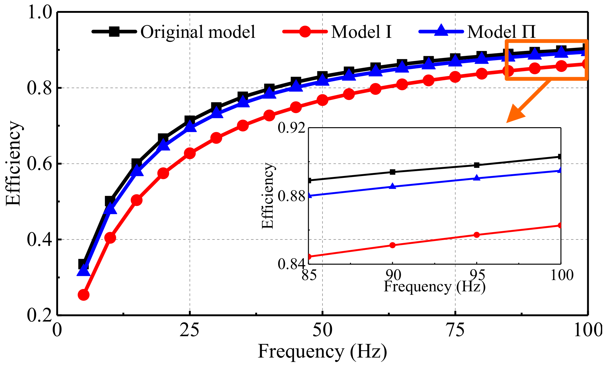
6.4. Loss and Efficient Characteristic

The waveforms of the loss versus frequency for the three machines are shown in Figure 21. It can be found that the losses of Model Ⅱ is higher than that of the original model and Model Ⅰ. The main reason is that the winding resistance of Model Ⅱ is larger than that of the original model and Model.
The waveforms of the efficiency versus frequency in the three machines are shown in Figure 22, when the current density of the three machines is 6 A/mm2. The efficiencies of the three machines increase with the frequency and tend to be stable. Besides, the efficiency of Model Ⅱ is slightly lower than that of the original model, but higher than that of Model Ⅰ in various frequencies.

7. Conclusions

This paper adopts 120°-TW to investigate the problem found in previous researches caused when the first five and the last five slots in each side are half-filled due to the distributed and short-pitch windings. And the detent force of the DSPMLSM is investigated. In order to suppress the detent force, which results from the longitudinal end effect and the slot effect, a slot-shift primary structure is adopted, in which the slots on the two sides of the primary are staggered by a certain distance. The analytical and the simulation results indicate that when the value of the shift-distance coefficient S is 0.5, the end force, the cogging force, and the detent force can be reduced to the minimum values, respectively. Simultaneously, the amplitude of the thrust is improved by rearranging the 120°-TW. The results exhibit the slot-shift primary structure possesses some advantages, which can be concluded as below.
(1)
The detent force when S is 0.5 is 70.19% lower than that when the coefficient S is 0.
(2)
The thrust fluctuation of Model Ⅰ is reduced by 19.21% comparing with the original machine.
(3)
The back-EMF of Model Ⅱ is 31.86% higher than that of Model Ⅰ. Additionally, the thrust of Model Ⅱ is 39.78% higher than that of Model Ⅰ.
Therefore, the optimal method in this paper is available in the detent force reduction and thrust improvement of the 120°-DSPMLSM. However, the drawback of the slot-shift primary structure is the unbalance of three-phase winding resistances and inductances. Besides, fluctuation of the thrust is larger. Therefore, further optimization of the 120°-TWDSPMLSM will be a future investigation and shall be reported soon.

Author Contributions

Conceptualization, J.S., X.C. and R.N.; methodology, X.C.; software, X.C.; formal analysis, Y.L. and Y.H.; data curation, X.C.; writing—original draft preparation, X.C. All authors have read and agreed to the published version of the manuscript.

Funding

This research was funded by Natural Science Foundation of China under grant number 51777060, in part by the Major Special Project for Collaborative Innovation in Zhengzhou under grant number 20XTZX12023 and the China Postdoctoral Science Foundation under grant number 2020M682342. Besides, this research was also funded by the Science and Technology Funds of North China Institute of Science and Technology under grant number JSJ1204B and JD2013B01.

Institutional Review Board Statement

Not applicable.

Informed Consent Statement

Not applicable.

Data Availability Statement

Not applicable.

Conflicts of Interest

The authors declare no conflict of interest.

References

  1. Ji, J.H.; Xue, R.; Zhao, W.X.; Tao, T.; Huang, L.S. Simplified Three-Vector-Based Model Predictive Thrust Force Control with Cascaded Optimization Process for a Double-Side Linear Vernier Permanent Magnet Motor. IEEE Trans. Power Electron. 2020, 35, 10681–10689. [Google Scholar] [CrossRef]
  2. Song, J.C.; Zhao, J.W.; Dong, F.; Zhao, J.; Song, X.W. Demagnetization Fault Detection for Double-Sided Permanent Magnet Linear Motor Based on Three-Line Magnetic Signal Signature Analysis. IEEE-ASME Trans. Mech. 2020, 25, 815–827. [Google Scholar] [CrossRef]
  3. Zhang, Z.J.; Luo, M.Z.; Duan, J.A.; Kou, B.Q. Performance Analysis of Double-Sided Permanent Magnet Linear Synchronous Motor with Quasi-Sinusoidal Ring Windings. IEEE Trans. Energy Convers. 2020, 35, 1465–1474. [Google Scholar] [CrossRef]
  4. Zhao, J.; Mou, Q.S.; Zhu, C.C.; Chen, Z.; Li, J. Study on a Double-Sided Permanent-Magnet Linear Synchronous Motor with Reversed Slots. IEEE-ASME Trans. Mech. 2021, 26, 3–12. [Google Scholar] [CrossRef]
  5. Li, B.; Zhao, J.; Liu, X.D.; Guo, Y.G.; Hu, H.Z.; Li, J. Detent Force Reduction of an Arc-Linear Permanent-Magnet Synchronous Motor by Using Compensation Windings. IEEE Trans. Ind. Electron. 2017, 64, 3001–3011. [Google Scholar] [CrossRef]
  6. Zhu, Y.W.; Jin, S.M.; Chung, K.K.; Cho, Y.H. Control-Based Reduction of Detent Force for Permanent Magnet Linear Synchronous Motor. IEEE Trans. Magn. 2009, 45, 2827–2830. [Google Scholar] [CrossRef]
  7. Wang, M.L.; Li, L.Y.; Pan, D.H. Detent Force Compensation for PMLSM Systems Based on Structural Design and Control Method Combination. IEEE Trans. Ind. Electron. 2015, 62, 6845–6854. [Google Scholar] [CrossRef]
  8. Shin, J.S.; Watanabe, R.; Koseki, T.; Kim, H.J.; Takada, Y. The Design for Cogging Force Reduction of a Double-Sided Transverse Flux Permanent Magnet Linear Synchronous Motor. IEEE Trans. Magn. 2014, 50, 8205104. [Google Scholar] [CrossRef]
  9. Kim, T.W.; Chang, J.H. Analysis of Thrust Characteristics Considering Step-Skew and Overhang Effects in Permanent Magnet Linear Synchronous Motor. IEEE Trans. Magn. 2015, 51, 8102104. [Google Scholar]
  10. Ma, M.N.; Zhang, J.P.; Yu, J.K.; Zhang, H.; Jin, Y.X. Analytical Methods for Minimizing Detent Force in Long-Stator PM Linear Motor Including Longitudinal End Effects. IEEE Trans. Magn. 2015, 51, 8204104. [Google Scholar] [CrossRef]
  11. Zhu, Y.W.; Lee, S.G.; Chung, K.S.; Cho, Y.H. Investigation of Auxiliary Poles Design Criteria on Reduction of End Effect of Detent Force for PMLSM. IEEE Trans. Magn. 2009, 45, 2863–2866. [Google Scholar] [CrossRef]
  12. Inoue, M.; Sato, K. An approach to a suitable stator length for minimizing the detent force of permanent magnet linear synchronous motors. IEEE Trans. Magn. 2000, 36, 1890–1893. [Google Scholar] [CrossRef]
  13. Hu, H.Z.; Liu, X.D.; Zhao, J.; Guo, Y.G. Analysis and Minimization of Detent End Force in Linear Permanent Magnet Synchronous Machines. IEEE Trans. Ind. Electron. 2018, 65, 2475–2486. [Google Scholar] [CrossRef]
  14. Seo, S.W.; Jang, G.H.; Koo, M.M.; Choi, J.Y. Characteristic Analysis of the Influence of Auxiliary Teeth and Notching on the Reduction of the Detent Force of a Permanent Magnet Linear Synchronous Machine. IEEE Trans. Appl. Supercon. 2018, 28, 5203705. [Google Scholar] [CrossRef]
  15. Huang, X.Z.; Qian, Z.Y.; Tan, Q.; Li, J.; Zhou, B. Suppressing the Thrust Ripple of the Permanent Magnet Linear Synchronous Motors with Different Pole Structures by Setting the Modular Primary Structures Differently. IEEE Trans. Energy Convers. 2018, 33, 1815–1824. [Google Scholar] [CrossRef]
  16. Kwon, Y.S.; Kim, W.J. Detent-Force Minimization of Double-Sided Interior Permanent-Magnet Flat Linear Brushless Motor. IEEE Trans. Magn. 2016, 52, 8201609. [Google Scholar] [CrossRef]
  17. Kwon, Y.S.; Kim, W.J. Steady-State Modeling and Analysis of a Double-Sided Interior Permanent-Magnet Flat Linear Brushless Motor with Slot-Phase Shift and Alternate Teeth Windings. IEEE Trans. Magn. 2016, 52, 8205611. [Google Scholar] [CrossRef]
  18. Huang, X.Z.; Ji, T.P.; Li, L.Y.; Zhou, B.; Zhang, Z.R.; Gerada, D.; Gerada, C. Detent Force, Thrust, and Normal Force of the Short-Primary Double-Sided Permanent Magnet Linear Synchronous Motor with Slot-Shift Structure. IEEE Trans. Energy Convers. 2019, 34, 1411–1421. [Google Scholar] [CrossRef]
  19. Chai, X.B.; Si, J.K.; Nie, R.; Wang, Y.Q.; Qi, G.; Dong, L.H. Comparative Analysis of Double-sided Permanent Magnet Linear Synchronous Machines with 120° Phase Belt Toroidal and Concentrated Windings. In Proceedings of the 13th International symposium on Linear Drives for Industry Applications (LDIA), Wuhan, China, 1–3 July 2021. [Google Scholar]
  20. Baatar, N.; Yoon, H.S.; Pham, M.T.; Shin, P.S.; Koh, C.S. Shape Optimal Design of a 9-pole 10-slot PMLSM for Detent Force Reduction Using Adaptive Response Surface Method. IEEE Trans. Magn. 2009, 45, 4562–4565. [Google Scholar] [CrossRef]
  21. Huang, X.Z.; Yu, H.C.; Zhou, B.; Li, L.Y.; Gerada, D.; Gerada, C.; Qian, Z.Y. Detent-Force Minimization of Double-Sided Permanent Magnet Linear Synchronous Motor by Shifting One of the Primary Components. IEEE Trans. Ind. Electron. 2020, 67, 180–191. [Google Scholar] [CrossRef]
  22. Bianchi, N.; Bolognani, S.; Cappello, A.D.F. Reduction of Cogging Force in PM Linear Motor by Pole-Shifting. IEEE Proc. Electr. Power Appl. 2005, 152, 703–709. [Google Scholar] [CrossRef]
Figure 1. Structure of the 120°-TWDSPMLSM.
Energies 15 00943 g001
Figure 2. Structure of the 120°-TWDSPMLSM.
Energies 15 00943 g002
Figure 3. Detent force of the 120°-TWDSPMLSM.
Energies 15 00943 g003
Figure 4. Slot-shift structure of the 120°-TWDSPMLSM.
Energies 15 00943 g004
Figure 5. Simulation model of the end force.
Energies 15 00943 g005
Figure 6. End forces of the DSPMLSM with different shifted distance.
Energies 15 00943 g006
Figure 7. The end force harmonic varying as the shift distance coefficient S.
Energies 15 00943 g007
Figure 8. Simulation model of the cogging force.
Energies 15 00943 g008
Figure 9. Cogging forces of the DSPMLSM with different S.
Energies 15 00943 g009
Figure 10. Harmonic amplitudes of the cogging forces varying with different S.
Energies 15 00943 g010
Figure 11. Detent force of the DSPMLSM with different S.
Energies 15 00943 g011
Figure 12. End force, cogging force, and detent force vary with S.
Energies 15 00943 g012
Figure 13. Slot electrical potential star vectograms of the 120°-TWDSPMLSM. (a) Upper conductors, (b) Lower conductors, (c) Lower conductors (120°).
Energies 15 00943 g013
Figure 14. Model Ⅰ.
Figure 14. Model Ⅰ.
Energies 15 00943 g014
Figure 15. Model Ⅱ.
Figure 15. Model Ⅱ.
Energies 15 00943 g015
Figure 16. The single-phase vectordiagram of synthetic electromotive force (1/4 model).
Energies 15 00943 g016
Figure 17. Back-EMF waveforms.
Energies 15 00943 g017
Figure 18. Thrust waveforms.
Energies 15 00943 g018
Figure 19. Thrust versus current density.
Energies 15 00943 g019
Figure 20. Thrust versus current angle at the same current density.
Energies 15 00943 g020
Figure 21. Loss versus frequency.
Energies 15 00943 g021
Figure 22. Efficiency versus frequency.
Energies 15 00943 g022
Table 1. Geometric parameters of 120°-TWDSPMLSM.
QuantityValue
Pole pitch (mm)16.5
Primary lamination thickness (mm)60
Secondary-core thickness (mm)7
Slot pitch (mm)11
Slot width (mm)6
Slot height (mm)15
PM height (mm)3
PM width (mm)12.4
Rated power (W)397.17
Maximum thrust (N)320.87
Maximum velocity (m/s)3.3
Maximum stroke (mm)1000
Publisher’s Note: MDPI stays neutral with regard to jurisdictional claims in published maps and institutional affiliations.

