Article

Granular PCM-Enhanced Plaster for Historical Buildings: Experimental Tests and Numerical Studies

by
Eleonora Baccega
* and
Michele Bottarelli
Department of Architecture, University of Ferrara, Via Quartieri 8, 44121 Ferrara, Italy
*
Author to whom correspondence should be addressed.
Energies 2022, 15(3), 975; https://doi.org/10.3390/en15030975
Submission received: 23 December 2021 / Revised: 17 January 2022 / Accepted: 26 January 2022 / Published: 28 January 2022
(This article belongs to the Special Issue Green Buildings for Carbon Neutral)

Abstract

:
The construction sector is among the major players responsible for global energy consumption and therefore related emissions, both because of the constantly increasing indoor air quality standard which requires increasingly higher energy demands as well as the great share of historical buildings which are now obsolete and are not up to date with current regulations. Phase change materials (PCMs) applied on the building envelope represent a feasible possibility to improve the performance of existing buildings, also the historical ones, increasing their thermal inertia without violating any legal restriction or causing further alterations to the structure. More specifically, focus of this research was on the addition of a granular paraffin PCM into a lime-based plaster. Experimental tests at lab scale and numerical simulations with COMSOL Multiphysics were carried out to characterize the plasters realized, namely one reference lime-based plaster and one with incorporated 10% by mass of granular PCM (named REFp and PCMp, respectively). The behavior of these plasters applied on the exterior side of a wall was then simulated and compared in terms of temperatures and heat fluxes. However, considering that the estimated thermal conductivity of the reference lime-based plaster was lower than the values found in literature, the simulations were carried out considering an additional plaster, namely a lime-based plaster (renamed LITp), whose properties were found in literature and considered quite representative of a consistent share of existing historical buildings. Great improvements were observed from the application of PCM into the plaster, with reductions of the incoming energy between 9% and 18%.

1. Introduction

The building and construction sector is the greatest energy-consuming sector [1] with a great share of the primary energy supply deriving from fossil fuels [2]. It represents more than 30% of the world’s energy consumption and nearly 40% of the total energy-related CO2 emissions [3,4]. The constantly increasing demand for thermal comfort inside buildings is leading to greater energy requirements for ventilation and air-conditioning [5] which, without any improvement to the actual scenario, is estimated to increase by 80% till 2050 if compared to 2010 levels [6]. The causes of this are to be found first of all in the change in people’s lifestyle, where living standards are higher and higher with a consequent rise of the internal heat gains due to the electrical equipment, then in the impact of the urban heat island effect especially in crowded cities, and lastly in the decrease of the cost of the cooling equipment [7]. In addition to this, a great share of the built environment consists of historical and obsolete buildings which are usually very expensive to maintain and are still excluded from the obligation to adapt to newer standards, most of the time because of architectural and technological incompatibilities [8]. In Europe, almost one building out of three is considered historical [9], and in Italy, the highest energy consumer country in the whole Mediterranean area [10], one out of five was built even before 1919 [11]. On the basis of these considerations, the refurbishment of existing buildings seems crucial to achieve the energy and climate objectives of the European Union for 2050 [12]. If on one side technological innovations are continuously allowing an improvement of systems performance, on the other the interventions on the building envelope are limited due to an industrialization that often prevents a standardized application of low-cost and low-impact strategies. Among the methods that nowadays are used to improve the building envelopes’ performances, the thermal energy storage (TES) [13] by means of the latent heat of phase change materials (PCMs) can act as a passive cooling strategy through which the building envelope’s thermal inertia is increased and whose aim is the improvement of the thermal comfort for occupants by reducing indoor temperature fluctuations [14,15]. The integration of PCM, in fact, can make the building envelope dynamic and able to adapt to different conditions. This feature in a building envelope is of increasing importance both to moderate the energy demand for air conditioning as well as to improve its resistance towards climate change [16,17,18]. Moreover, PCM can be a feasible solution in many scenarios in which more radical interventions are forbidden due to legislative restrictions, both in the case of single buildings characterized by aesthetical, historical, or cultural qualities, as well as in the case of buildings inserted in larger protected areas, such as historical city centers. The incorporation of PCM in construction materials is among their most interesting applications and one of the major benefits is the improvement of the thermal properties with minimal change to the building design. For what concerns the building façade, the addition of PCM to the plaster is one of the possible solutions, which allows a relatively simple application on the outermost layer of a wall. This could be performed both on the interior and on the exterior sides, to reduce the consumption for heating or for cooling. This type of application has gained increasing attention and several researchers have focused on it during the last decade [5,10,17,18,19,20,21,22,23,24,25,26,27,28,29,30].
In Figure 1, the potential effect of PCM applied to plaster is depicted. In this case, the PCM was intended for a summer application and therefore to reduce the energy requirement for cooling.
With PCM, the peak indoor temperature at daytime is lower and occurs at a delayed time if compared to the reference case without PCM thanks to the latent heat absorbed by the PCM during its melting phase change. During the night the PCM releases the latent heat during its solidification phase change and this brings about a slightly higher indoor temperature during the coolest hours of the day. In general, with the application of PCM, a more stable indoor temperature with minor fluctuations between daytime and nighttime can be achieved with a consequent reduction of the energy required for cooling which, in Figure 1, is represented by the colored area.
This study is focused on the evaluation of the application of a lime-based plaster mixed with a granular PCM on the exterior side of a wall. A lime-based plaster was chosen, which was preferred to a cement-based one, because it was among the most common materials in ancient structures [31,32] and is more suitable for the restoration as there is a lower risk of damaging the wall on which it is applied [21]. In addition to this, lime plasters have good thermal properties, even though they are not those of an insulator [33]. For what concerns the PCM, granules of paraffin were selected. This is because paraffin is the most used PCM in the case of applications on the building envelope, with an incidence of 87.5% [34], thanks to its chemical stability, non-corrosiveness, low cost, recyclability, low supercooling phenomenon, and no phase segregation [22,35].

2. Materials and Methods

The first part of this study was conducted experimentally, where two plaster samples were tested under controlled conditions. The tests aimed at estimating the thermal conductivity and calibrating a numerical model implemented with COMSOL Multiphysics V5.5 [36] through which the plaster’s specific heat and the PCM latent heat were estimated. Once the thermal properties of the plasters were obtained, an additional model was implemented to simulate the effects on temperatures and heat fluxes of the different plasters applied on the exterior side of a wall.

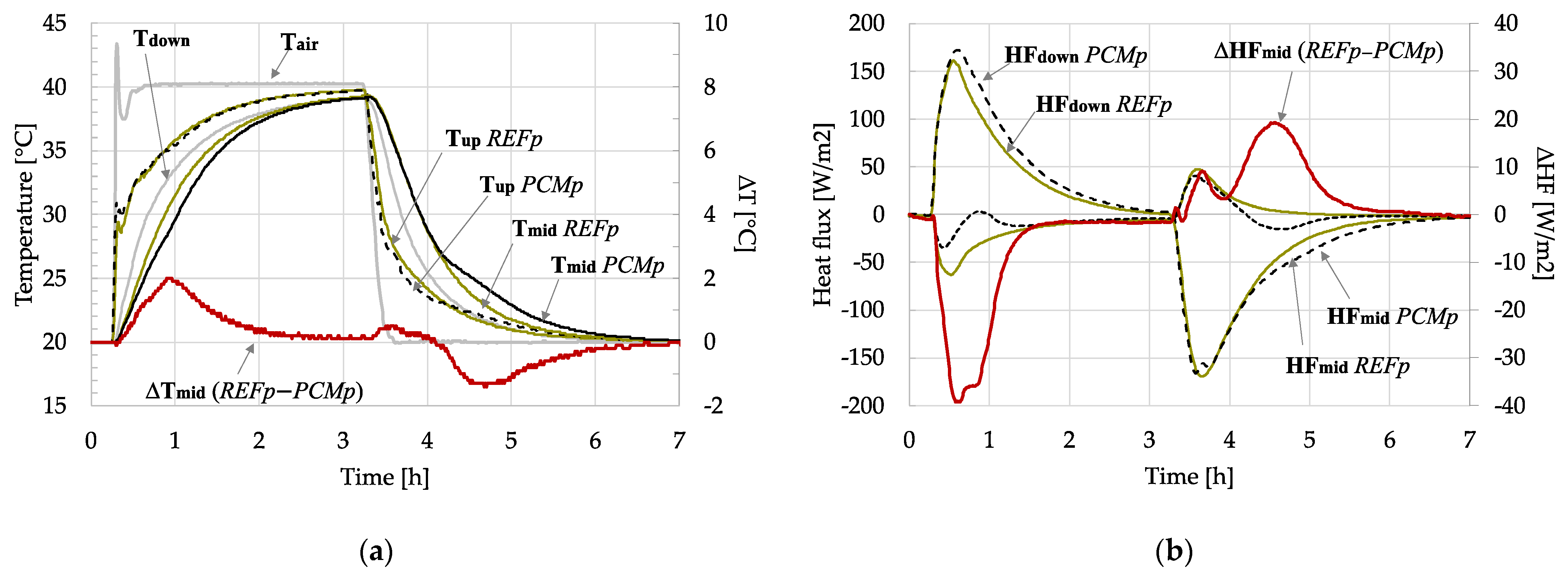
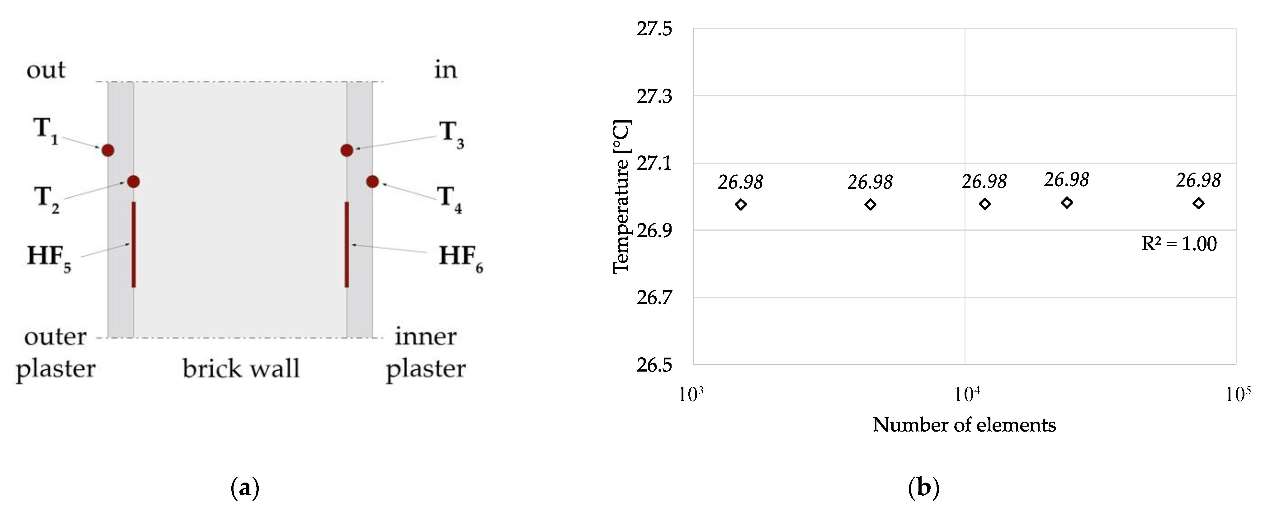
2.1. Experimental Set Up

An experimental set up was realized to carry out the tests in a climatic chamber and is depicted in Figure 2. It is made of a 0.20 × 0.15 × 0.020 m3 plaster sample and a 0.20 × 0.15 × 0.028 m3 masonry tile positioned on a 0.003 m aluminum foil under which four Peltier cells are fixed. These are coupled with finned air exchangers and small fans in order to dissipate the heat on the warmer side. Moreover, a frame of XPS was added on the vertical surfaces to limit heat transfer on the edges and wooden elements are used to stiffen the set up. All the tests were taken in a climatic chamber [37] where temperature and heat flux sensors were used for the monitoring activity. T-type thermocouples (accuracy: 0.5 K), and heat flow plates (accuracy: 5% at 23 °C) were connected to a datalogger [38] through which data were acquired each 30 s. On both the surfaces of the masonry tile, shallow indentations were realized in order to allocate the heat flux sensors, so that their thickness would not affect the measures. Moreover, some thermal paste was applied in correspondence with each layer to limit the contact resistance as much as possible.
The uncertainty of the sensors used was calculated as the standard deviation of the arithmetic mean, through the following Equation (1) [39], and the values are reported in Table 1:
u ( x ¯ ) = 1 n ( n 1 ) j = 1 n ( x j x ¯ ) 2
where n is the number of data and x j x ¯ is the deviation.
Two plaster samples were realized; one was just a lime-based plaster used as reference (here indicated as REFp) while the other one was the reference in which 10% by mass of granular PCM was added (here indicated as PCMp). The plaster used was a bioplaster based on hydraulic lime NHL 3.5 which was supplied by Fassa S.r.l. [40]. The PCM used was a granular paraffin PCM with an indicated melting temperature of 28 °C, supplied by PCM Products Ltd. [41], which was introduced as a result of the European project TESSe2b [42] and its application is yet to be completely investigated. The masonry tile used was the result of a historical building’s restoration and its thermal properties were the object of the research, as well.
The densities of the materials used in the experimental tests were estimated and the values are reported in Table 2. The addition of the PCM into the plaster brought about a reduction of the density of 16%.

2.2. Thermal Properties Estimation

The set up realized and depicted in Figure 2 was subjected to some tests in the climatic chamber under different conditions in order to estimate the materials’ thermal conductivity and then the experimental data were used to obtain the specific heat and the PCM latent heat through the numerical model implemented in COMSOL Multiphysics.

2.2.1. Thermal Conductivity

At first tests were conducted in steady-state conditions to evaluate the thermal conductivity λ [W/(m·K)] of both the samples and the masonry tile. The plaster samples were arranged, one at a time, in the set up previously described in the climatic chamber where a fixed temperature and a constant fan speed were set. For a more consistent value of the thermal conductivities estimated, the tests were carried out in multiple steps, in which different voltages were set to the Peltier cells through a multi-range DC power supply [43]. Therefore, different temperatures were obtained on the aluminum plate (Tdown) and so the estimated value of the thermal conductivity for each plaster sample was the average of the values obtained in each step. In the case of PCMp the test was conducted with two different temperatures in the climatic chamber in order to consider both the PCM phases. In Table 2, the values in terms of temperature and heat flux during the steady-state tests are summarized.
The thermal conductivities of the materials were estimated through Equation (2) and the values are reported in Table 3:
λ = d q ¯ Δ T
where d is the thickness of the sample [m], q ¯ is the average heat flux [W/m2], and ΔT is the difference between the temperatures on the surfaces [K] [12,44]. More specifically, the thermal conductivity of the plaster sample was estimated considering as ΔT the difference between Tup and Tmid, while for that of the masonry tile the difference considered was between Tmid and Tdown.
In addition to this, it was possible to also estimate the convective heat transfer coefficient on top of the plaster surface through Equation (3):
h = q ¯ Δ T
where in this case ΔT is the difference between Tair and Tup. The value estimated is in the range between 24 and 28 W/(m2·K). The uncertainties of the thermal conductivities and of the convective heat transfer coefficient were calculated as in Equation (4) [39] and the values are reported in Table 3:
u c 2 ( y ) = i = 1 n ( f x i ) 2 u 2 ( x i )
where f is the function defined as Y = f ( X 1 , X 2 , , X n ) .
The thermal conductivity of the reference plaster is somewhat lower than what can be found in literature. In Table 4 the thermal properties of some lime plasters found in literature are reported. For what concerns the PCM plaster, the addition of PCM causes a reduction of the thermal conductivity of 22.5%.

2.2.2. Specific Heat of the Masonry Tile

An additional experimental set up was realized to estimate the specific heat of the masonry tile, and therefore reduce the number of properties to be estimated through the numerical model to the properties of the plaster samples only. Part of the set up realized is depicted in Figure 3a and consisted of a 0.15 m × 0.30 m × 0.028 m masonry tile with an XPS frame to ensure a mono-dimensional heat flux. A heat flux meter and a T-type thermocouple were placed on each surface of the tile using thermal paste to improve the thermal contact and avoid any air gap, and a third T-type thermocouple was inserted into a hole in the middle of the tile. The test was conducted in the climatic chamber which was initially set at 20 °C, and once all the thermocouples on the tile read the same temperature, the chamber was brought to 40 °C until all the thermocouples read the same temperature again. It was then brought again to 20 °C and the test stopped as the thermocouples read the same value. In Figure 3b, the values acquired during the test are depicted. The specific heat [J/(kg·K)] was estimated to be about 800 J/(kg·K) through the following Equation (5):
c p , t i l e = Q m · Δ T = t 2 t 1 q ¯ d t ρ d ( T e n d T i n i t )
where q ¯ is the average heat flux read by the two heat flux meters (HFright, HFleft) [W/m2], ρ is the density [kg/m3], d is the thickness [m], and Tinit and Tend are the initial and final temperatures of the surface, respectively [K] [44].
The thermal properties of the masonry tile appear to be in accordance with those found in literature [47,50] and are summarized in Table 5:

2.2.3. Specific Heat and PCM Latent Heat

The specific heat of the plasters and the latent heat of the PCM were estimated through the calibration of a numerical model implemented in COMSOL Multiphysics of an unsteady experimental test. Both REFp and PCMp samples were placed in the climatic chamber which was initially set at 20 °C with constant speed. As the system reached a steady-state condition, the temperature of the chamber was set to 40 °C for 3 h and then set again at 20 °C.
In Figure 4a, the temperatures collected for both the reference and the PCM plaster sample are depicted. Even though the quantity of PCM added to the plaster was quite low, the differences between the REFp and PCMp samples are clearly visible. In fact, in the case of the PCMp, the temperature between the plaster sample and the masonry tile (Tmid) changes more slowly that the REFp, especially in correspondence with the phase change. The red line represents the difference between the values of Tmid of the two samples at each acquisition step: the difference peak was of 2 K during the melting of the PCM and it was of 1.4 K during the solidification one. In Figure 4b the heat flux values collected for both plasters are depicted, and the differences in this case are even more visible. During the heating, the heat flux between the PCM plaster sample and the masonry tile (HFmid) was much lower than that of the reference one. During the melting phase, the peak reduction reached nearly 45% and values were close to 0 W/m2 in correspondence with the peak melting temperature. During the cooling phase, the peak reduction was of 15% and the difference was of nearly 20 W/m2 in correspondence with the peak cooling temperature. The data collected during the unsteady-state tests were used to calibrate a numerical model of the experimental set up in COMSOL Multiphysics, through which the plaster’s specific heat and the PCM latent heat were estimated. This model was implemented in a “Heat Transfer in Solids” 3D domain with time-varying boundary conditions. Considering that during the steady-state conditions the values of the two heat flux meters (HFmid and HFdown) were the same, an adiabatic condition was applied on the vertical surfaces instead of modeling the XPS frame. The other conditions applied were the temperature of the aluminum plate (Tdown) on the lower surface, the air temperature in the chamber (Tair), and the convective heat transfer coefficient on the upper surface of the model, which was calculated as in Equation (2). First, the model of the reference plaster was calibrated and therefore its specific heat was estimated. Then, the other model was calibrated and the PCM specific and latent heat were estimated, using the following Equation (6) [51,52]:
c p , P C M p ( T ) = ( 1 r ) · c p , R E F p + r · ( 1 H i ( T ) ) · ( c p , P C M s + h s l · D i ( T ) ) + r · H i ( T ) · ( c p , P C M l + h s l · D i ( T ) )
where c p , R E F p is the specific heat of the plaster [J/(kg·K)], c p , P C M s and c p , P C M l are the solid and the liquid PCM specific heat, respectively [J/(kg·K)], r is the mass ratio of PCM in plaster, H i ( T ) is a dimensionless variable corresponding to the liquid fraction of the PCM in a range between 0 and 1, h s l is the latent heat of fusion [kJ/kg], and D i ( T ) is a normalized Dirac’s pulse [K−1].
As represented in Figure 5a, the experimental data were used to assume the PCM properties in terms of phase change temperatures and relative ranges. The colored areas depicted were identified considering the difference between the heat flux measured (HFmid) with the PCM plaster with respect to that measured with the reference one. It can be noticed that the granular PCM charges and discharges at different temperatures, and the melting range is wider than the solidification one. More specifically, the melting was identified in a range of 12 K between 22 °C and 34 °C and therefore the peak was set at 28 °C, while the solidification range was identified between 21 °C and 27 °C so the peak was set in correspondence with its average value, so 24 °C. This temperature identification allowed the implementation in COMSOL Multiphysics of H i ( T ) and D i ( T ) functions, as described in Equation (3) and depicted in Figure 5b.
The calibration of the test with the reference plaster is depicted in Figure 6a while that of the PCM plaster is depicted in Figure 6b. The mesh was hexahedral and the mesh independence was verified as represented in Figure 7. Then the root mean square error (RMSE) was calculated as in Equation (7) and the values obtained are reported in Table 6:
R M S E = i = 1 N ( y i y ^ i ) 2 N
where yi is the actual measured value and y ^ i is the predicted one. After the calibration of the models, the specific heat of the reference plaster was estimated to be about 800 J/(kg·K), while the specific heat and latent heat of the PCM were estimated to be 2220 J/(kg·K) and 75 kJ/kg, respectively. This means that, out of the phase change, the specific heat of the PCM plaster is 17% higher than the reference one.

2.2.4. Numerical Model of a Perimeter Wall

After having estimated the thermal properties of the two plasters, a new model was realized and a small sample of a perimeter wall was implemented in order to predict the behavior of these plasters under real conditions. The model was a portion of 0.4 × 0.4 m2 which consisted of a brick layer covered with 0.03 m of plaster on both sides. As the main objective of this study was to evaluate the applicability of PCM in the case of energy refurbishment of historical buildings, no insulation was added intentionally. In order to extend the present research to a greater number of buildings, two models were realized in COMSOL Multiphysics, one with a 0.25 m brick layer and the other with a 0.38 m brick layer, corresponding to a two-brick- and three-brick-thick wall, respectively. The model was implemented coupling the “Heat Transfer in Solids” and the “Surface-to-Surface radiation” physics, so that it was possible to define the radiative heat transfer separately. On the interior side of the wall, a fixed temperature of 26 °C with a convective heat transfer coefficient of 10 W/(m2·K) was set, while on the exterior side the temperature and solar radiation fixed were obtained from a database of a weather station located at the TekneHub laboratory of the University of Ferrara and a convective heat transfer coefficient of 25 W/(m2·K) was applied. Apart from the interior and the exterior sides, all the other surfaces were considered adiabatic. The behavior of the wall samples was simulated during some consecutive days in mid-August, 2019. These were characterized by high peak temperatures during the day and consistent differences of temperature between day and night, which allow the PCM to charge and discharge completely. The boundary conditions, namely temperature and solar radiation, of the simulation days are depicted in Figure 8, together with the sol-air temperature (Tsol-air) which was calculated as in Equation (8) [15,53]:
T s o l a i r = T a i r + α I g R s e
where α is the absorption coefficient of the surface, which was considered of 0.48 [54], I g is the global solar radiation [W/m2], and R s e is the external surface resistance [m2·K/W], supposing a convective heat transfer coefficient of 25 W/(m2·K), in accordance with the recommendations of ISO 6946 [55].
However, as previously mentioned, the thermal conductivity estimated for the reference plaster is somewhat lower than what can be found in literature or in technical datasheets. It seemed therefore that simulating this reference plaster might not be representative of a great share of the existing buildings and so an additional plaster was taken into consideration and compared to the two realized samples.
The properties of this plaster (here indicated as LITp) are depicted in Table 7 together with a recap of the thermal properties of the other simulated plasters. The focus of the simulations was the summer evaluation of the application of PCM on the external side of a wall. For this reason, the simulations that will be compared will have the same brick and interior plaster layers; this last one was the reference plaster (REFp), and the only difference will be the plaster applied as exterior layer. In Figure 9a the nomenclature and the position of the sensors used for the comparison are depicted. The simulations were carried out for some consecutive days, but the results were considered only from the second day on, to avoid the initial conditions applied from interfering with the results. The mesh applied was hexahedral, made of 1500 elements; however, the mesh independence was verified by carrying out the same simulation with higher numbers of elements, as depicted in Figure 9b.

3. Results

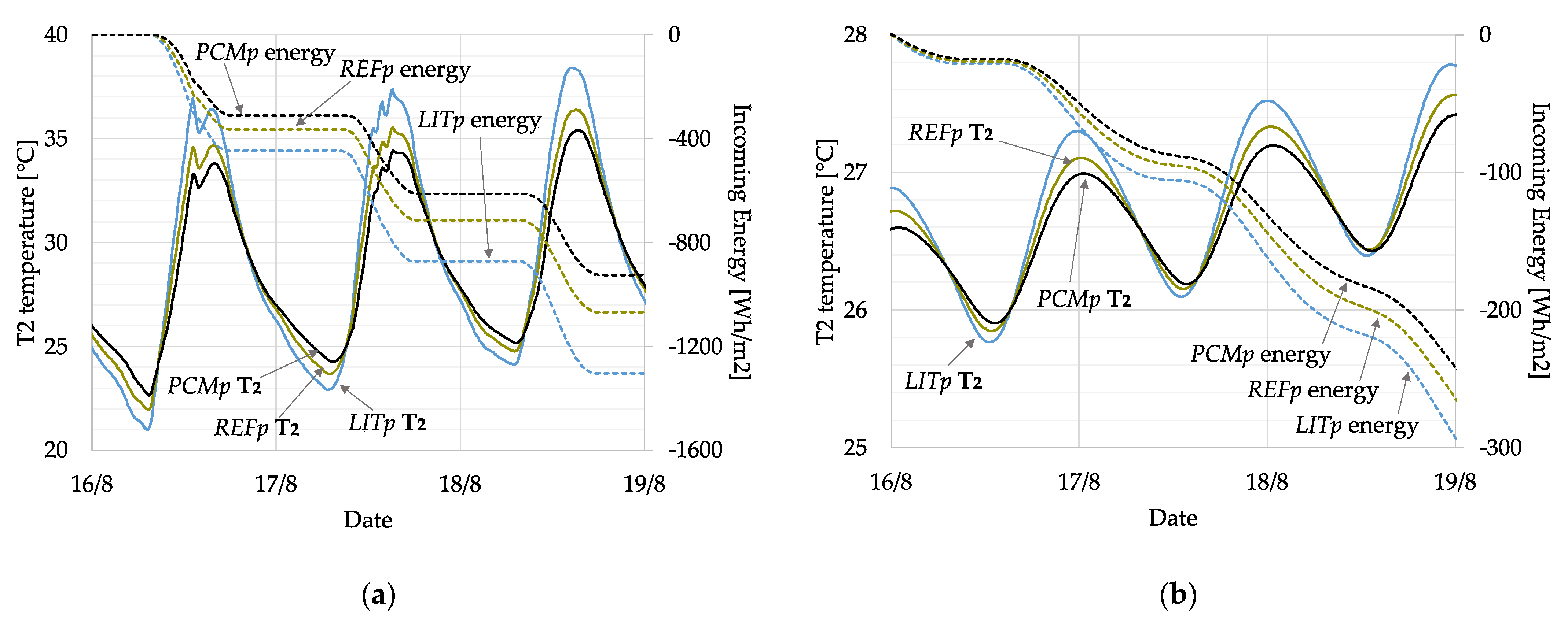
3.1. Two-Brick-Thick Wall (25 cm)

The first simulations were carried out considering the wall with 0.25 m brick layer. In Figure 10a are depicted the temperatures between the outer plaster and the brick layer (T2) together with the incoming energy (HF5) for the three simulated configurations. Relevant differences between the two lime plasters (REFp and LITp) are visible, which means that the lime plaster used for the experimental tests has quite good thermal insulation properties. However, the effect of the addition of PCM is clearly visible. In fact, if compared to REFp, a reduction of nearly 2 K is visible during the hottest hours while during the night the temperatures are slightly higher, between 0.5 K and 1 K. Greater differences are visible in the comparison with LITp: during the hottest hours of the day the wall with PCMp reaches temperatures almost 4 K lower than the wall with LITp while during the night the temperatures are about 1 K higher. These differences are also consistent in terms of incoming energy: on average, during the hottest hours, the incoming heat flux in the wall with PCMp is almost 10 W/m2 lower than the wall with REFp and nearly 30 W/m2 lower than the wall with LITp. Considering the total incoming energy between the outer plaster and the brick layer in the simulated days, the amount in the case of the wall with PCMp was about 924 Wh/m2, in the case of REFp 1068 Wh/m2, and in the case of LITp 1303 Wh/m2. Moving to the inner side of the wall, in Figure 10b, the temperatures and the incoming energy between the brick layer and the inner plaster are depicted. The differences between the configurations were obviously consistently reduced but the same trend as the one previously described can be noticed. In terms of temperature, during the hottest hours the differences are barely visible: between PCMp and REFp it is of less than 0.2 K while between PCMp and LITp it is of nearly 0.5 K. However, considering the incoming energy, the amount in the case of the wall with PCMp was about 241 Wh/m2, 264 Wh/m2 in the case of REFp, and 292 Wh/m2 in the case of LITp.

3.2. Three-Brick-Thick Wall (38 cm)

The same simulations were carried out considering a wall with a thicker brick layer, which was set to 0.38 m, equivalent to a three-brick-thick wall. In fact, historical buildings were frequently characterized by massive walls. In Figure 11a, the temperatures and the incoming energies between the outer plaster and the brick layer (T2 and HF5) are depicted. The results obtained are almost the same as the previous simulations, with slightly lower total incoming energy values. The difference, however, is of about 1%, so the same considerations as the previous case can be seen. For what concerns the inner side of the wall, in Figure 11b are depicted the temperatures and the incoming energy between the brick layer and the inner plaster. In terms of temperature, the differences are barely visible and reach differences up to 0.2 K only during the hottest hours of the days. However, looking at the total incoming energy, the amount in the case of the wall with PCMp was about 133 Wh/m2, 146 Wh/m2 in the case of REFp, and 162 Wh/m2 in the case of LITp.

4. Discussion

For what concerns the first simulated wall, namely the two-brick-thick wall, on the basis of the total incoming energy between the brick layer and the inner plaster the PCMp brought about a reduction of about 9% and 18% if compared to REFp and LITp, respectively. In Figure 12a is depicted the percentage difference between the incoming energies in the three configurations where LITp is 100%. It is visible that with LITp, namely, the lime-based plaster whose properties were found in literature, the total incoming energy, therefore the energy requirement for cooling, is the highest among the three configurations.
In the case of REFp, the lime-based plaster that was realized and tested in the lab, the incoming energy is almost 10% lower than the configuration with LITp, while in the case of PCMp, the reduction is higher and almost 18% lower than LITp. Another aspect that is worth noticing is depicted in Figure 12b. Here the temperatures on the innermost side of the wall (T4) are represented together with the sol-air temperature (Tsol-air) and, in the case of PCMp, a greater delay in reaching the peak temperature is visible. More specifically, in the case of LITp the delay was of slightly more than 10 h, in the case of REFp the delay was of 10.5 h while in the case of PCMp the delay was of 11 h.
For what concerns the second simulated wall, namely the three-brick-thick wall, even though the differences of temperatures and heat fluxes in absolute terms between the configurations are more limited than the previous case, the percentage reduction is still visible. In fact, the reduction in the case of PCMp is still of about 9% if compared to REFp and 18% if compared to LITp, respectively.
In Figure 13a the percentage difference between the incoming energies in the three configurations with respect to LITp is summarized. As for the two-brick-thick wall, in the case of REFp the incoming energy, which affects the energy requirement for cooling, is almost 10% lower than LITp, while in the case of PCMp the reduction is of more than 18%. In Figure 13b the sol-air temperature (Tsol-air) is depicted together with the temperature reached on the inner side of the wall (T4) with focus on one day of simulation in order to highlight the delay in reaching the peak inner temperature. In the case of the LITp the delay is of 16 h and 20 min, in the case of the REFp it is of 16 h and 50 min, while in the case of the LITp it is of 16 h and 20 min. This means that the addition of PCM brings about an increase of the delay of 4% if compared to REFp and of 7% if compared to LITp.
It therefore emerged that, independently from the wall thickness, the incoming energy in the case of LITp is the highest among the three plasters considered while in the case of PCMp it is the lowest one and about 18% lower than LITp.

5. Conclusions

The addition of granular paraffin PCM into lime-based plaster was considered in this paper as a feasible solution for the improvement of energy performance of historical buildings, which are often protected by legislative restrictions that prevent many of the most popular interventions. The plaster chosen was a lime-based one because of its compatibility with historical structures, while the PCM was paraffin as it is the most compliant for an application on the building envelope. Samples of a reference lime-based plaster (REFp) and its enhancement containing 10% by mass of granular PCM (PCMp) were realized and tested under controlled conditions at lab scale. Some of the properties of the plasters were experimentally estimated, namely the density and the thermal conductivity, while the specific heat and the PCM latent heat were estimated through the calibration of a numerical model of the experimental set up implemented in COMSOL Multiphysics. From the properties estimated, the addition of PCM causes a reduction of 16% of the density and of 22.5% of the thermal conductivity, while as regards the specific heat there is an increase of the 16%. In COMSOL Multiphysics, a 3D model was then implemented of a portion of a wall in which the behavior under real conditions was simulated. Besides the two plasters realized and tested in the lab, an additional plaster was defined. This was because it was considered that the thermal properties of the reference lime-based plaster (REFp) might not be representative of many of the existing buildings; therefore, another lime-based plaster whose properties were found in literature (LITp) was simulated. The simulations were carried out for some consecutive summer days. The different plasters were applied on the outer side of a wall, and two different wall thicknesses were tested: the first with a 0.25 m brick layer, corresponding to a two-brick-thick wall, and then with a 0.38 m brick layer, corresponding to a three-brick-thick layer wall. In both cases, results showed the same trend. The first consideration regarded the comparison between the two lime plasters: the application of REFp instead of LITp brought about lower temperatures during the day and consequently lower incoming heat fluxes. In both cases the reduction of the incoming energy is of more than 9%. For what concerned the addition of PCM into the plaster, the performance of PCMp brought about lower temperatures and lower incoming heat fluxes than both the two lime plasters. More specifically, with both the wall thicknesses, the reduction of the total incoming energy is of about 9% if compared to REFp and of about 18% if compared to LITp.
This research was carried out experimentally only for the preliminary part to characterize the plaster sample realized; therefore, even though in the climatic chamber the differences between the plasters are clearly visible, it might be interesting to experimentally investigate whether under real outdoor conditions the monitored behavior is confirmed. For this reason, further steps of this research will involve an in-field experimental monitoring activity and at the same time further considerations might be, for instance, on the effect of the application of PCM changing the phase change temperatures or on the investigation on the efficacy of a winter application instead of a summer one.

Author Contributions

Conceptualization, E.B. and M.B.; methodology, E.B. and M.B.; software, E.B. and M.B.; validation, M.B.; formal analysis, E.B. and M.B.; investigation, E.B. and M.B.; resources, M.B.; data curation, E.B.; writing—original draft preparation, E.B.; writing—review and editing, E.B. and M.B.; visualization, E.B.; supervision, E.B and M.B. All authors have read and agreed to the published version of the manuscript.

Funding

This research received no external funding.

Institutional Review Board Statement

Not applicable.

Informed Consent Statement

Not applicable.

Data Availability Statement

The data presented in this study are available on request from the corresponding author. The data are not publicly available due to still ongoing research.

Acknowledgments

The materials used to realize the plaster samples were provided by Fassa S.r.l. and PCM Products Ltd.

Conflicts of Interest

The authors declare no conflict of interest.

References

  1. Sinka, M.; Bajare, D.; Jakovics, A.; Ratnieks, J.; Gendelis, S.; Tihana, J. Experimental testing of phase change materials in a warm-summer humid continental climate. Energy Build. 2019, 195, 205–215. [Google Scholar] [CrossRef]
  2. Lizana, J.; Chacartegui, R.; Barrios-Padura, A.; Valverde, J.M. Advances in thermal energy storage materials and their applications towards zero energy buildings: A critical review. Appl. Energy 2017, 203, 219–239. [Google Scholar] [CrossRef]
  3. Asadi, E.; da Silva, M.G.; Antunes, C.H.; Dias, L. Multi-objective optimization for building retrofit strategies: A model and an application. Energy Build. 2012, 44, 81–87. [Google Scholar] [CrossRef]
  4. 2020 Global Status Report for Buildings and Construction. Available online: https://globalabc.org/resources/publications/2020-global-status-report-buildings-and-construction (accessed on 13 January 2021).
  5. Pavlík, Z.; Trník, A.; Keppert, M.; Pavlíková, M.; Žumár, J.; Černý, R. Experimental Investigation of the Properties of Lime-based Plaster-Containing PCM for Enhancing the Heat-Storage Capacity of Building Envelopes. Int. J. Thermophys. 2014, 35, 767–782. [Google Scholar] [CrossRef]
  6. Ürge-Vorsatz, D.; Cabeza, L.F.; Serrano, S.; Barreneche, C.; Petrichenko, K. Heating and cooling energy trends and drivers in buildings. Renew. Sustain. Energy Rev. 2015, 41, 85–98. [Google Scholar] [CrossRef] [Green Version]
  7. Pandey, B.; Banerjee, R.; Sharma, A. Coupled EnergyPlus and CFD analysis of PCM for thermal management of buildings. Energy Build. 2021, 231, 110598. [Google Scholar] [CrossRef]
  8. Dalla Mora, T.; Cappelletti, F.; Peron, F.; Romagnoni, P.; Bauman, F. Retrofit of an historical building toward NZEB. Energy Procedia 2015, 78, 1359–1364. [Google Scholar] [CrossRef] [Green Version]
  9. Eurostat. Census Hub HC53. Available online: https://ec.europa.eu/CensusHub2/query.do?step=selectHyperCube&qhc=false (accessed on 8 May 2020).
  10. Coppola, L.; Coffetti, D.; Lorenzi, S. Cement-Based Renders Manufactured with Phase-Change Materials: Applications and Feasibility. Adv. Mater. Sci. Eng. 2016, 2016, 7254823. [Google Scholar] [CrossRef] [Green Version]
  11. Rapporto Bes. Il Benessere Equo e Sostenibile in Italia. Available online: https://www.istat.it/it/files//2013/03/9_Paesaggio-e-patrimonio-cult.pdf (accessed on 8 September 2021).
  12. Bianco, L.; Serra, V.; Fantucci, S.; Dutto, M.; Massolino, M. Thermal insulating plaster as a solution for refurbishing historic building envelopes: First experimental results. Energy Build. 2015, 95, 86–91. [Google Scholar] [CrossRef]
  13. Wijesuriya, S.; Tabares-Velasco, P.C.; Biswas, K.; Heim, D. Empirical validation and comparison of PCM modeling algorithms commonly used in building energy and hygrothermal software. Build. Environ. 2020, 173, 106750. [Google Scholar] [CrossRef]
  14. Akeiber, H.; Nejat, P.; Majid, M.Z.A.; Wahid, M.A.; Jomehzadeh, F.; Famileh, I.Z.; Calautit, J.K.; Hughes, B.R.; Zaki, S.A. A review on phase change material (PCM) for sustainable passive cooling in building envelopes. Renew. Sustain. Energy Rev. 2016, 60, 1470–1497. [Google Scholar] [CrossRef]
  15. Sá, A.V.; Azenha, M.; de Sousa, H.; Samagaio, A. Thermal enhancement of plastering mortars with Phase Change Materials: Experimental and numerical approach. Energy Build. 2012, 49, 16–27. [Google Scholar] [CrossRef]
  16. Cabeza, L.F.; Castell, A.; Barreneche, C.; de Gracia, A.; Fernandez, A.I. Materials used as PCM in thermal energy storage in buildings: A review. Renew. Sustain. Energy Rev. 2011, 15, 1675–1695. [Google Scholar] [CrossRef]
  17. Lachheb, M.; Younsi, Z.; Naji, H.; Karkri, M.; Ben Nasrallah, S. Thermal behavior of a hybrid PCM/plaster: A numerical and experimental investigation. Appl. Therm. Eng. 2017, 111, 49–59. [Google Scholar] [CrossRef]
  18. Navarro, L.; de Gracia, A.; Castell, A.; Cabeza, L.F. Thermal behaviour of insulation and phase change materials in buildings with internal heat loads: Experimental study. Energy Effic. 2015, 8, 895–904. [Google Scholar] [CrossRef] [Green Version]
  19. Cunha, S.; Alves, V.; Aguiar, J.B.; Ferreira, V.M. Use of phase change materials microcapsules in aerial lime and gypsum mortars. Cem. Wapno Beton. 2011, 17–21. [Google Scholar]
  20. Sukontasukkul, P.; Sutthiphasilp, T.; Chalodhorn, W.; Chindaprasirt, P. Improving thermal properties of exterior plastering mortars with phase change materials with different melting temperatures: Paraffin and polyethylene glycol. Adv. Build. Energy Res. 2019, 13, 220–240. [Google Scholar] [CrossRef]
  21. Ventolà, L.; Vendrell, M.; Giraldez, P. Newly-designed traditional lime mortar with a phase change material as an additive. Constr. Build. Mater. 2013, 27, 1210–1216. [Google Scholar] [CrossRef]
  22. Pavlík, Z.; Fort, J.; Pavlíková, M.; Pokorny, J.; Trník, A.; Černý, R. Modified lime-cement plasters with enhanced thermal and hygric storage capacity for moderation of interior climate. Energy Build. 2016, 126, 113–127. [Google Scholar] [CrossRef]
  23. Kheradmand, M.; Aguiar, J.; Azenha, M. Assessment of the thermal performance of plastering mortars within controlled test cells. In Proceedings of the Congresso Luso-Brasileiro de Materiais de Construçao Sustentaveis, Guimarães, Portugal, 5–7 March 2014. [Google Scholar]
  24. Maleki, B.; Khadang, A.; Meddah, H.; Alizadeh, M.; Kazemian, A.; Ali, H.M. Development and thermal performance of nanoencapsulated PCM/plaster wallboard for thermal energy storage in buildings. J. Build. Eng. 2020, 32, 101727. [Google Scholar] [CrossRef]
  25. Paranjothi, G.; Odukomaiya, A.; Cui, S.; Bulk, A. Evaluation of phase change plaster/paste composites for building envelopes. Energy Build. 2021, 253, 111372. [Google Scholar] [CrossRef]
  26. Fort, J.; Trník, A.; Pavlíková, M.; Pavlík, Z.; Černý, R. Fabrication of dodecanol/diatomite shape-stabilized PCM and its utilization in interior plaster. Int. J. Thermophys. 2018, 39, 137. [Google Scholar] [CrossRef]
  27. Karaipekli, A.; Sari, A. Development and thermal performance of pumice/organic PCM/gypsum composite plasters for thermal energy storage in buildings. Sol. Energy Mater. Sol. Cells 2016, 149, 19–28. [Google Scholar] [CrossRef]
  28. Fort, J.; Pavlíková, M.; Trník, A.; Pavlík, Z. Thermal behaviour of new type of plaster with PCM admixture. Appl. Mech. Mater. 2015, 710, 3–7. [Google Scholar] [CrossRef]
  29. Soudian, S.; Berardi, U.; Laschuk, N. Development and thermal-optical characterization of a cementitious plaster with phase change materials and thermochromic paint. Sol. Energy 2020, 205, 282–291. [Google Scholar] [CrossRef]
  30. Theodoridou, M.; Kyriakou, L.; Ioannou, I. PCM-enhanced lime plaster for vernacular and contemporary architecture. Energy Procedia 2016, 97, 539–545. [Google Scholar] [CrossRef] [Green Version]
  31. Baccega, E.; Bottarelli, M. Numerical and experimental evaluation of a granular PCM-enhanced plaster for historic building application. In Proceedings of the International Building Performance Simulation Association 2021, Bruges, Belgium, 1–3 September 2021. in press. [Google Scholar]
  32. Moropoulou, A.; Bakolas, A.; Anagnstopoulou, S. Composite materials in ancient structures. Cem. Concr Compos. 2005, 27, 295–300. [Google Scholar] [CrossRef]
  33. Stefanidou, M.; Assael, M.; Antoniadis, K.; Matziaroglou, G. Thermal conductivity of building materials employed in the preservation of traditional structures. Int. J. Thermophys. 2010, 31, 844–851. [Google Scholar] [CrossRef]
  34. Cui, Y.; Xie, J.; Liu, J.; Wang, J.; Chen, S. A review on phase change material application in building. Adv. Mech. Eng. 2017, 9, 1–15. [Google Scholar] [CrossRef] [Green Version]
  35. Drissi, S.; Ling, T.-C.; Mo, K.H.; Eddhahak, A. A review of microencapsulated and composite phase change materials: Alteration of strength and thermal properties of cement-based materials. Renew. Sustain. Energy Rev. 2019, 110, 467–484. [Google Scholar] [CrossRef]
  36. COMSOL Multiphysics Reference Manual. Available online: http://www.comsol.com (accessed on 19 November 2020).
  37. Memmert CTC 256. Available online: https://www.memmert.com/products/climate-chambers/environmental-test-chambers/CTC256/ (accessed on 12 January 2021).
  38. Almemo Ahlborn. Available online: https://www.ahlborn.com/download/pdfs/kap01/eng/5690n-e.pdf (accessed on 8 September 2021).
  39. ISO/IEC GUIDE 98-3:2008.Uncerttainty of measurement. Part 3: Guide to the Expression of Uncertainty in Measurement (GUM:1995). Available online: https://webstore.iec.ch/publication/11961 (accessed on 12 January 2021).
  40. Fassa, S.r.l. Available online: https://www.fassabortolo.it/it/prodotti/-/p/6/62/ex-novo-restauro-storico/intonaco-700-bio-intonaco-di-fondo-a-base-di-calce-idraulica-naturale-nhl-3-5-per-interni-ed-esterni (accessed on 22 October 2020).
  41. PCM Products Ltd. Available online: https://www.pcmproducts.net (accessed on 12 January 2021).
  42. TESSe2b-Thermal Energy Storage Systems for Energy Efficient Buildings. Available online: http://www.tesse2b.eu/tesse2b/home (accessed on 12 January 2021).
  43. GWInstek. Available online: https://www.gwinstek.com/en-global/products/detail/PSW-Series (accessed on 12 January 2021).
  44. Li, C.; Yu, H.; Song, Y. Experimental investigation of thermal performance of microencapsulated PCM-contained wallboard by two measurement modes. Energy Build. 2019, 184, 34–43. [Google Scholar] [CrossRef]
  45. Černý, R.; Kunca, A.; Tydlitat, V.; Drchalova, J.; Rovnanikova, P. Effect of pozzolanic admixtures on mechanical, thermal and hygric properties of lime plasters. Constr. Build. Mater. 2006, 20, 849–857. [Google Scholar] [CrossRef]
  46. Walker, R.; Pavia, S. Thermal and hygric properties of insulation materials suitable for historic fabrics. In Proceedings of the III International Congress on Construction and Building Research, Madrid, Spain, 14–16 December 2015. [Google Scholar]
  47. Akkurt, G.C.; Aste, N.; Borderon, J.; Buda, A.; Calzolari, M.; Chung, D.; Costanzo, V.; Del Pero, C.; Evola, G.; Huerto-Cardenas, H.E.; et al. Dynamic thermal and hygrometric simulation of historical buildings: Critical factors and possible solutions. Renew. Sustain. Energy Rev. 2020, 118, 109509. [Google Scholar] [CrossRef]
  48. Franco, G.; Magrini, A. Historical Buildings and Energy, 1st ed.; Springer: Cham, Switzerland, 2018; p. 60. [Google Scholar]
  49. Jerman, M.; Vejmelikovà, E.; Keppert, M.; Černý, R. Properties of plasters suitable for reconstruction of historical buildings. In Structural Studies, Repairs and Maintenance of Heritage Architecture XIII, 1st ed.; Brebbia, C.A., Ed.; WIT Press: Southampton, UK, 2013; pp. 369–378. [Google Scholar]
  50. Lucchi, E. Thermal transmittance of historical brick masonries: A comparison among standard data, analytical calculation procedures, and in situ heat flow meter measurements. Energy Build. 2017, 134, 171–184. [Google Scholar] [CrossRef]
  51. Bottarelli, M.; Bortoloni, M.; Su, Y.; Yousinf, C.; Aydın, A.A.; Georgiev, A. Numerical analysis of a novel ground heat exchanger coupled with phase change materials. Appl. Therm. Eng. 2015, 88, 369–375. [Google Scholar] [CrossRef]
  52. Bottarelli, M.; Bortoloni, M.; Su, Y. Heat transfer of underground thermal energy storage in shallow trenches filled with encapsulated phase change materials. Appl. Therm. Eng. 2015, 90, 1044–1051. [Google Scholar] [CrossRef]
  53. Kheradmand, M.; Azenha, M.; Castro-Gomes, J.; Aguiar, J. Energy saving potential of cement based mortar containing hybrid phase change materials applied in building envelopes. In Proceedings of the Sustainable Construction Materials & Technologies 4, Las Vegas, NA, USA, 7–11 August 2016. [Google Scholar]
  54. Yao, J.; Yan, C. Effects of solar absorption coefficient of external walls on building energy consumption. Int. J. Civ. Environ. Struct. Constr. Archit. Eng. 2011, 4, 208–210. [Google Scholar]
  55. UNI EN ISO 6946:2018 (Italian version of EN ISO 6946:2017). Building Components and Building Elements. Thermal Resistance and Thermal Transmittance. Calculation Method. Available online: http://store.uni.com/catalogo/uni-en-iso-6946-2018?josso_back_to=http://store.uni.com/josso-security-check.php&josso_cmd=login_optional&josso_partnerapp_host=store.uni.com (accessed on 12 January 2021).
Figure 1. Illustration of potential effect of PCM applied to plaster.
Energies 15 00975 g001
Figure 2. Experimental set up and sensors’ position.
Energies 15 00975 g002
Figure 3. (a) Portion of the set up realized to estimate the specific heat of the masonry tile. (b) Data collected during the test inside the climatic chamber.
Energies 15 00975 g003
Figure 4. (a) Temperatures collected for both the reference and the PCM plaster samples. The curves of Tair and Tdown were the same for both tests, therefore only one was depicted in the graph. Moreover, the red line is the difference between the values of Tmid for the reference plaster and the PCM one, respectively. (b) Heat fluxes collected for both the reference and the PCM plaster samples. The red line is the difference between the values of HFmid for the reference plaster and the PCM one, respectively.
Energies 15 00975 g004
Figure 5. (a) Melting and solidification temperature individuation and relative ranges through the comparison of the heat fluxes (HFmid) of REFp and PCMp. Colored areas indicate the phase change of the PCM (b) H i ( T ) and D i ( T ) functions implemented in COMSOL Multiphysics. The arrows indicate the direction of the curve.
Energies 15 00975 g005
Figure 6. Calibration of the unsteady–state tests. (a) Test with the reference plaster, (b) test with the PCM plaster.
Energies 15 00975 g006
Figure 7. Verification of the mesh independence of the experimental set up model.
Energies 15 00975 g007
Figure 8. Boundary conditions of the simulation days.
Energies 15 00975 g008
Figure 9. (a) Nomenclature and position and the sensors defined in COMSOL Multiphysics; (b) verification of the mesh independence of the wall model.
Energies 15 00975 g009
Figure 10. (a) Temperatures and incoming energy between the outer plaster and the 0.25 m brick layer (sensors T2 and HF5); (b) temperatures and incoming energy between the 0.25 m brick layer and the inner plaster (sensors T3 and HF6).
Energies 15 00975 g010
Figure 11. (a) Temperatures and incoming energy between the outer plaster and the 0.38 m brick layer (sensors T2 and HF5); (b) temperatures and incoming energy between the 0.38 m brick layer and the inner plaster (sensors T3 and HF6).
Energies 15 00975 g011
Figure 12. (a) Percentage comparison between the incoming energies in the case of the two-brick-thick wall; (b) detail of the temperature on the inner side of the wall for one of the days of the simulation and relative delay from Tsol-air peak temperature for the two-brick-thick wall.
Energies 15 00975 g012
Figure 13. (a) Percentage comparison between the incoming energies in the case of the three-brick-thick wall; (b) detail of the temperature on the inner side of the wall for the same day as Figure 9 and relative delay from Tsol-air peak temperature for the three-brick-thick wall.
Energies 15 00975 g013
Table 1. Uncertainties of the sensors used.
u ( x ¯ )
Tair [°C]±0.02
Tup [°C]±0.007
Tmid [°C]±0.02
Tdown [°C]±0.02
HFmid [W/m2]±0.06
HFdown [W/m2]±0.04
Table 2. Estimated densities of the material.
ρ [kg/m3]
Reference plaster (REFp)1517
PCM plaster (PCMp)1278
Masonry tile1607
Table 3. Temperature and heat flux values obtained from the steady-state tests.
REFpPCMp
ABCABCDEF
Tair [°C]25.025.045.0
Tup [°C]21.821.119.722.321.620.743.942.941.9
Tmid [°C]16.815.011.016.414.410.641.538.034.8
Tdown [°C]12.69.63.712.59.53.740.235.330.8
q ¯ [W/m2]76.195.4131.072.389.5120.127.155.681.8
λplaster [W/(m·K)]0.31 ± 0.0060.24 ± 0.005
λmasonry tile [W/(m·K)]0.50 ± 0.016
h [W/(m2·K)]25.70 ± 0.003
Table 4. Thermal properties of lime plasters found in literature.
ρ [kg/m3]λ [W/(m·K)]cp [J/(kg·K)]
[28]18610.86-
[30]16800.94887
[45]16600.73970
[46]18200.80863.9
[47]18000.70-
[48]18000.90840
[49]18051.042817
Table 5. Estimated thermal properties of the masonry tile.
ρ [kg/m3]λ [W/(m·K)]cp [J/(kg·K)]
Masonry tile16070.50800
Table 6. RMSE calculated for both calibrations.
REFpPCMp
Tup [°C]0.280.41
Tmid [°C]0.200.18
HFmid [W/m2]2.262.18
Table 7. Thermal properties of the plasters used in the simulations.
ρ [kg/m3]λ [W/(m·K)]cp [J/(kg·K)]
Reference plaster (REFp)15170.31800
PCM plaster (PCMp)12780.24930
Literature plaster (LITp)18200.73970
Publisher’s Note: MDPI stays neutral with regard to jurisdictional claims in published maps and institutional affiliations.

