
Torsional Deformation Analysis of Large Miter Gate under Different Operating Conditions


Abstract
:
1. Introduction
2. Modeling
2.1. Stress Analysis of Gate under Different Operating Conditions
2.1.1. Wind Load
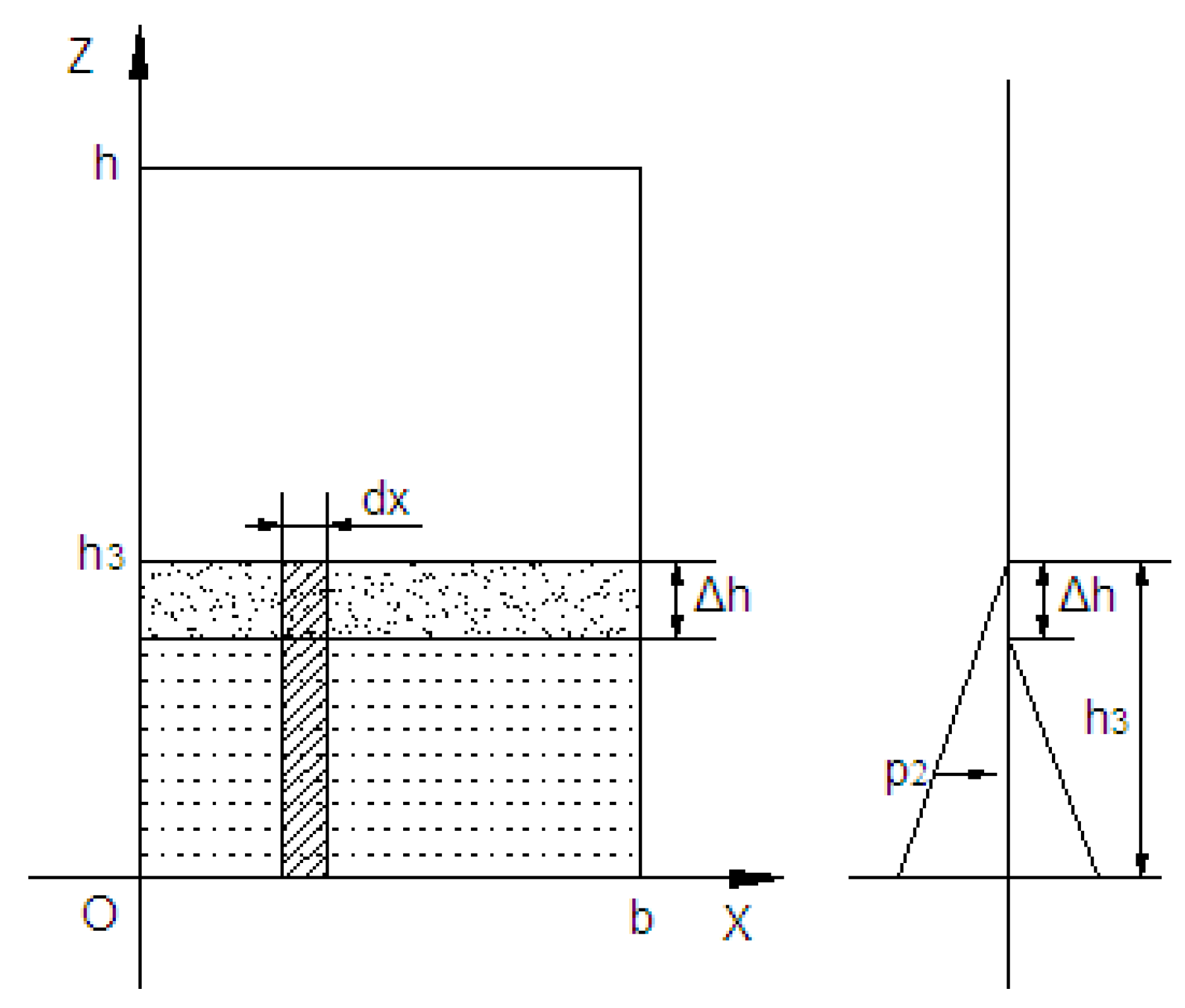
2.1.2. Water Pressure
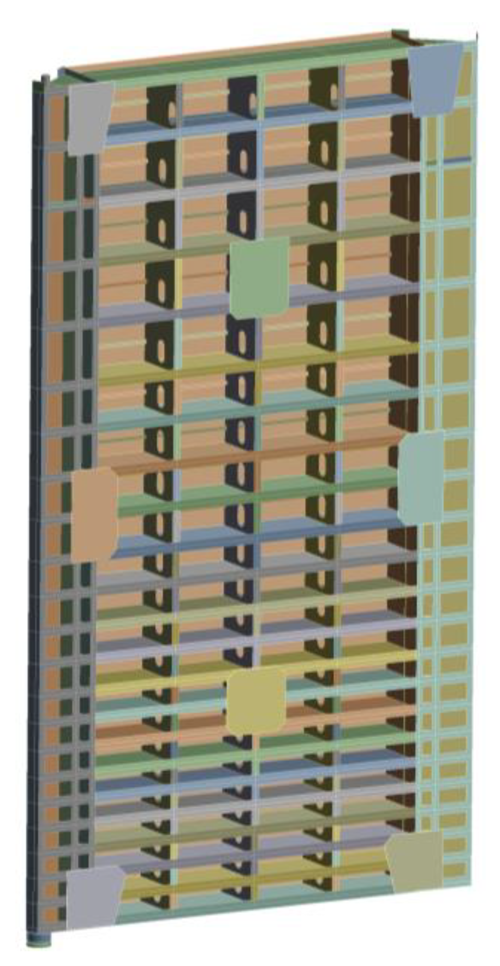
2.2. Model Establishment and Grid Division
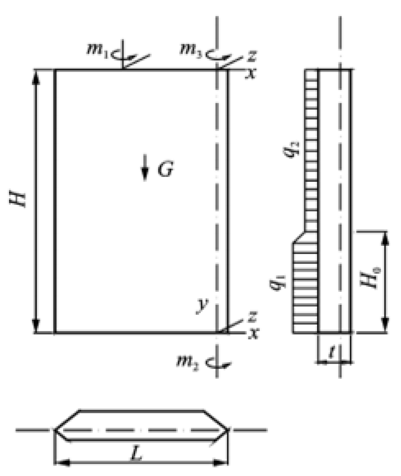
2.3. Setting of Load and Boundary Conditions
3. Results and Discussion
3.1. State 1
3.2. State 2
3.3. State 3
3.4. State 4
4. Conclusions
- (1)
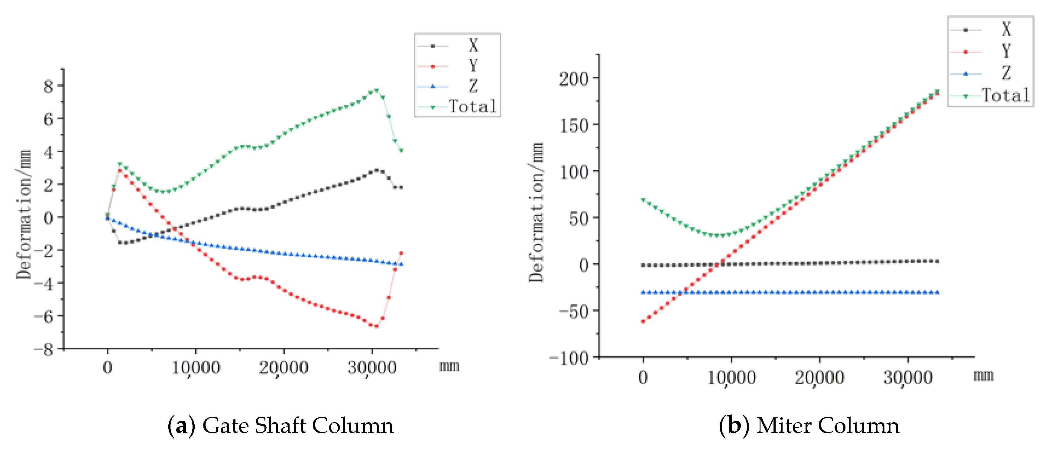
- The herringbone gate has obvious torsional deformation under its weight and when it is suspended freely. The door’s upper half bends to the downstream, and the lower half tilts to the upstream. The demarcation point in the middle is at the gate height of 7500 mm.
- (2)
- Under static State 1 of the herringbone gate, because the upstream and downstream have water pressure, and the difference is only 0.2 m, the deformation of the gate is not large, mainly in the Y direction, and the deformation is less than 1 mm. However, under static State 2 of the herringbone gate, the water level difference between the upstream and downstream is large, and the deformation in the Y direction is large. The main body of the gate is deformed toward the downstream.
- (3)
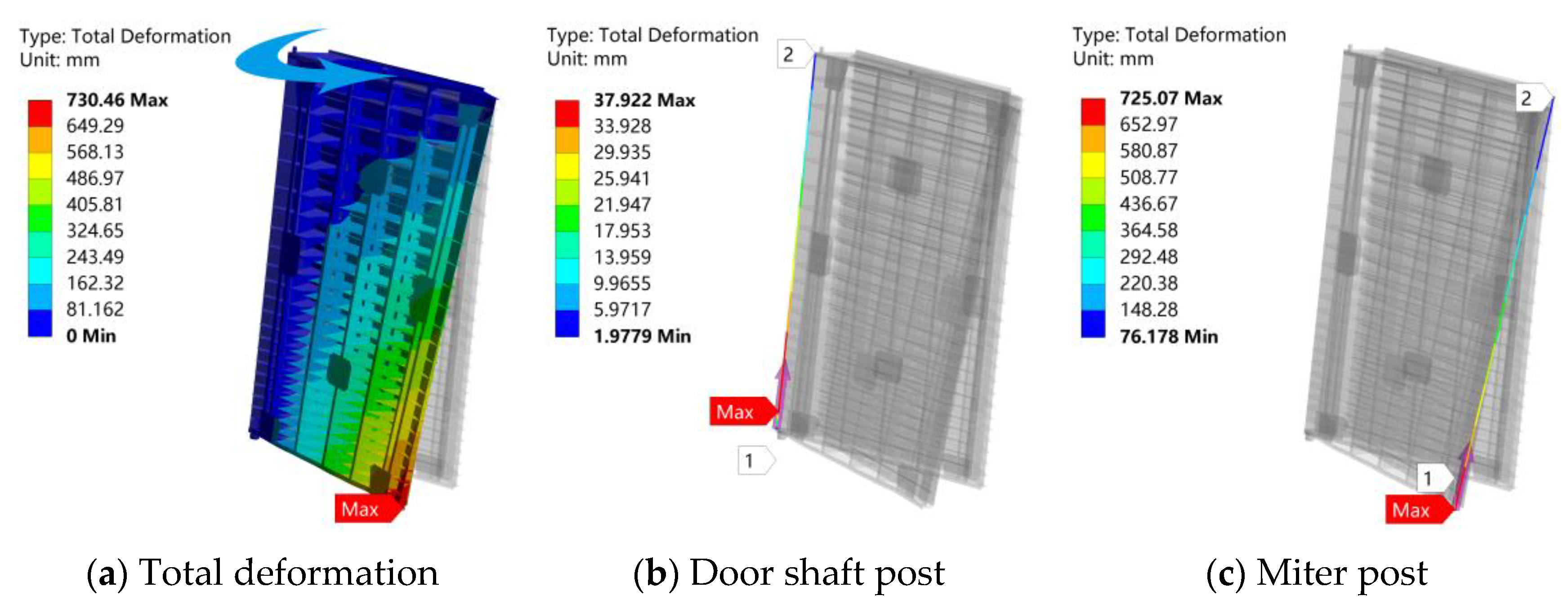
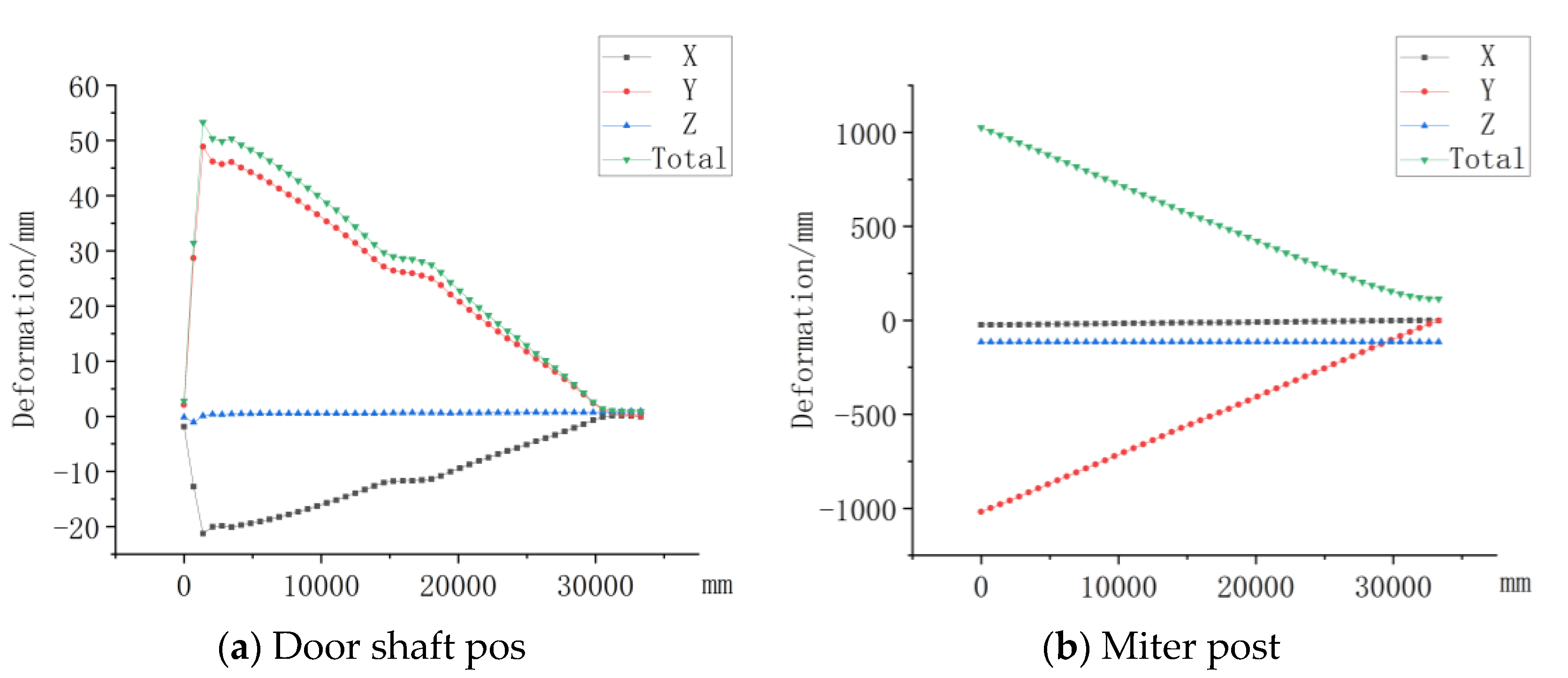
- Under the door opening and closing conditions, the gate is actuated by the push–pull rod and rotates around the door shaft column. The resistance generated by the upstream and downstream water level causes the gate to be deformed greatly in the lower half of the gate close to the miter column when the gate is closed. When the gate is closed, the gate is tilted to the upstream.
- (4)
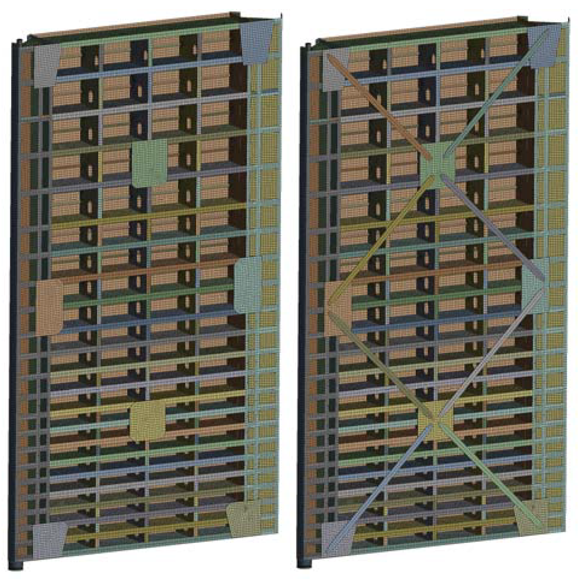
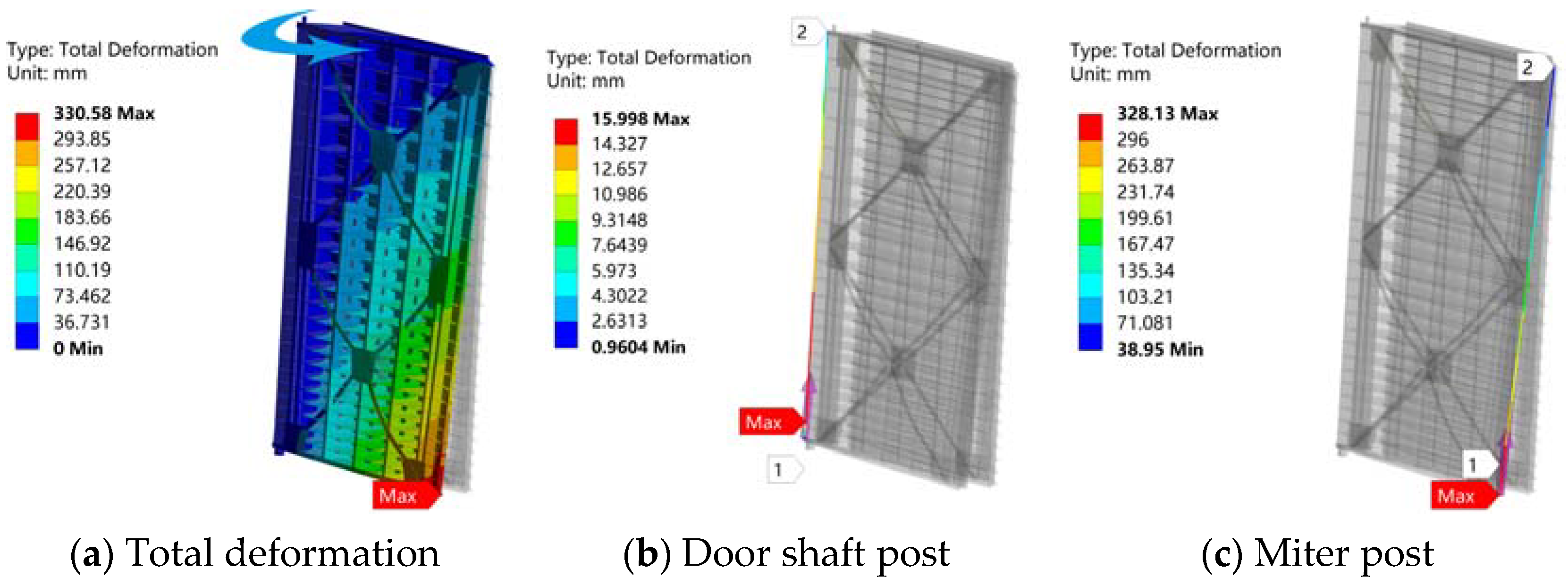
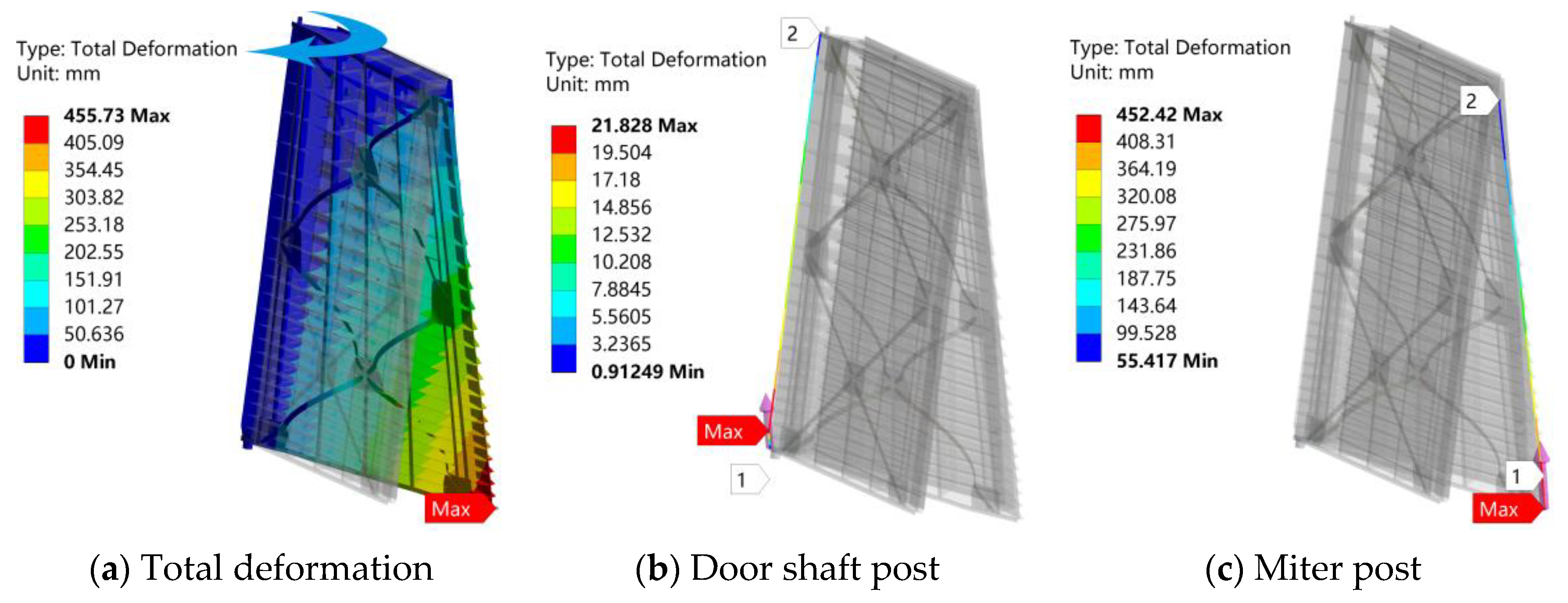
- Adding a back tie rod can effectively reduce the deformation of the gate under free-hanging, door opening, and closing conditions, but the effect of reducing the deformation of the gate in a static state is not very obvious. At the same time, under some working conditions, the back tie rod is still. Therefore, it will have an opposite effect on the deformation of the door shaft and increase the deformation. Thus, according to the deformation characteristics of the gate under different working conditions, the back pull rod should be set correspondingly to achieve the effect of reducing the deformation of the gate.
Author Contributions
Funding
Conflicts of Interest
References
- Zhao, X.Z.; Wang, R.F.; Wang, J.; Zhao, M.Y. The vibration characteristics analysis of miter gate based on ANSYS Workbench and vibration test. In Applied Mechanics and Materials; Trans Tech Publications Ltd.: Bäch, Switzerland, 2013; Volume 380, pp. 64–68. [Google Scholar]
- Cheng, X. Structural Analysis on Miter Gate of Ship Lock by Finite Element Method; Chongqing Jiaotong University: Chongqing, China, 2013. [Google Scholar]
- Department of the Army U.S.; Army Corps of Engineers. Engineering and Design of Lock Gates and Operating Equipment EM 1110-2-2703; Department of the Army U.S.: Washington, DC, USA; Army Corps of Engineers: Washington, DC, USA, 1984. [Google Scholar]
- He, Z.Y.; Zhang, H.Z. Research for Adjustment of Diagonal Prestress of Miter Gate of Permanent Ship Lock. China Water Transp. 2007, 9, 21–23. [Google Scholar]
- Xing, S.B. Design of prestressed back-tie rods in miter gate with floating box structure. Port Waterw. Eng. 2013, 8, 147–151. [Google Scholar]
- Xing, S.B. Research on Optimization Methods of Back-tie Rods Prestress of Miter Gate. J. Wuhan Univ. Technol. 2017, 41, 656–661. [Google Scholar]
- He, W.J. Study on some problems in mite lock gate design. J. Hydraul. Eng. 1999, 7, 18–22. [Google Scholar]
- Zhou, J.; Xu, Y.; Chu, X.; Zhou, Z. Optimization and adjustment of prestress of diagonal brace of mitre gate in Fankou Shiplock. Eng. J. Wuhan Univ. 2003, 1, 37–40. [Google Scholar]
- Xiao, X.Y.; Lu, S.Q. Study on Measurement of Energy Consumption for Cranes and Designing of Energy Saving Device. In Applied Mechanics and Materials; Trans Tech Publications Ltd.: Bäch, Switzerland, 2012; Volume 159, pp. 326–330. [Google Scholar]
- Liu, L.H.; Yang, B.; Shao, Q. Optimization of Diagonal Prestress of Miter Gatein Lock Based on Shape Function. J. Wuhan Univ. Technol. 2013, 37, 914–918. [Google Scholar]
- Billeter, P.; Staubli, T. Flow-induced multiple-mode vibrations of gates with submerged discharge. J. Fluids Struct. 2000, 14, 323–338. [Google Scholar] [CrossRef]
- Singh, D.K.; Pal, P.; Duggal, S.K. Free Vibration Analysis of Lock Gate Structure. J. Mech. 2020, 36, 507–520. [Google Scholar] [CrossRef]
- Singh, D.K.; Pal, P. Forced Vibration Analysis of Stiffened Lock Gate Structure. J. Sound Vib. 2021, 510, 116278. [Google Scholar] [CrossRef]
- Vega, M.A.; Hu, Z.; Todd, M.D. Optimal Maintenance Decisions for Deteriorating Quoin Blocks in Miter Gates Subject to Uncertainty in the Condition Rating Protocol. Reliab. Eng. Syst. Saf. 2020, 204, 107147. [Google Scholar] [CrossRef]
- Dang, T.V.; Morato, P.G.; Mai, Q.A.; Rigo, P. Optimal inspection and repair scheduling for mitre lock gates. Marit. Eng. 2019, 172, 95–103. [Google Scholar] [CrossRef]
- Ye, Y.F.; Yang, G.M. Finite Element Analysis of Structure Reinforcement of Gate with Downstream Seal. Yellow River 2015, 37, 110–112. [Google Scholar]
- Mahmoud, H.; Chulahwat, A.; Riveros, G. Fatigue and fracture life-cycle cost assessment of a Miter gate with multiple cracks. Eng. Fail. Anal. 2018, 83, 57–74. [Google Scholar] [CrossRef]
- Xi, X.Y.; Liu, H.; Ye, X.-Q.; Ke, M.-Y. Three dimensional finite element analysis and reliability of radial steel gate for Huazikou River sluice. Hydro-Sci. Eng. 2012, 5, 36–41. [Google Scholar]
- Yongxin, L.I. Three-dimensional Finite Element Analysis of Miter Gate Structure on Ship Lock. Water Resour. Power 2011, 29, 116–118. [Google Scholar]
- Buldgen, L.; Le Sourne, H.; Rigo, P. Fast strength assessment of mitre gates to ship impact. Int. J. Crashworthiness 2013, 18, 423–433. [Google Scholar] [CrossRef]
- Yan, Q.; Deng, X.F.; Wu, M.C. Static and Dynamic Characteristics Analysis of Drive Shaft Based on ANSYS Workbench. Auto Eng. 2019, 1, 37–40. [Google Scholar]
- Khatir, S.; Tiachacht, S.; Le Thanh, C.; Ghandourah, E.; Mirjalili, S.; Wahab, M.A. An improved Artificial Neural Network using Arithmetic Optimization Algorithm for damage assessment in FGM composite plates. Compos. Struct. 2021, 273, 114287. [Google Scholar] [CrossRef]
- Shicheng, H.; Jialing, Z.; Jian, R.; Bing, C.; Ting, C. Speed Distribution of 100-year Extreme Winds in Lower-reaches of the Yangtze. J. Appl. Meteorol. Seience 2009, 20, 437–442. [Google Scholar]
- Li, Y.J. Spatial and Temporal Characteristics of Near-Surface Wind Speed and Its Influencing Factors in the Middle and Lower Reaches of Yangtze River. Master’s Thesis, Hunan Normal University, Changsha, China, 2019. [Google Scholar]
- Huangfu, Y.; Zeng, J.; Ma, H.; Dong, X.; Han, H.; Zhao, Z. A flexible-helical-geared rotor dynamic model based on hybrid beam-shell elements. J. Sound Vib. 2021, 511, 116361. [Google Scholar] [CrossRef]
- Zhao, X.H.; Li, Z.Q.; Yuan, Y.C. Discussion and Verification of Shell-Solid Element Connection Mode in Ship Finite Element Model. Ship Eng. 2021, 43, 107–115. [Google Scholar]
- Xiao, X.; Waddell, C.; Hamilton, C.; Xiao, H. Quality Prediction and Control in Wire Arc Additive Manufacturing via Novel Machine Learning Framework. Micromachines 2022, 13, 137. [Google Scholar] [CrossRef] [PubMed]
- Jinbiao, Z.; Wei, Z.; Pengfei, W. Research and Application of Cross Spatial Grid Method in Combined Box Girder Bridge with Corrugated Steel Webs. IOP Conf. Ser. Earth Environ. Sci. 2020, 587, 012052. [Google Scholar] [CrossRef]
- Wang, Z.P.; Li, X.X. Optimization analysis on back-tie rods prestress of super-large miter gate. Yangtze River 2020, 51, 164–167. [Google Scholar]
- Yang, S.J. Transient dynamics finite element simulation analysis of the bottom hinge of the triangular gate. Low Carbon World 2016, 1, 77–78. [Google Scholar]


| Height above Ground (m) | 10 | 15 | 20 | 30 |
|---|---|---|---|---|
| 1 | 1.15 | 1.25 | 1.42 |
| State | Gravity | Wind Load | The Minimum Water Pressure in Upper Reaches | Water Pressure in Lower Reaches | The Maximum Water Pressure in Upper Reaches | Bottom Pivot Constraint | Top Pivot Constraint | Miter Column Constraint | Push–Pull Rod Restraint |
|---|---|---|---|---|---|---|---|---|---|
| 1 | ✔ | ✔ | ✔ | ||||||
| 2 | ✔ | ✔ | ✔ | ✔ | ✔ | ✔ | ✔ | ||
| 3 | ✔ | ✔ | ✔ | ✔ | ✔ | ✔ | |||
| 4 | ✔ | ✔ | ✔ | ✔ | ✔ | ✔ |
| The Setting of Back Tie Rod | Total Deformation of Gate | Gate Shaft Column | Miter Column | ||||||
|---|---|---|---|---|---|---|---|---|---|
| X | Y | Z | Total Deformation | X | Y | Z | Total Deformation | ||
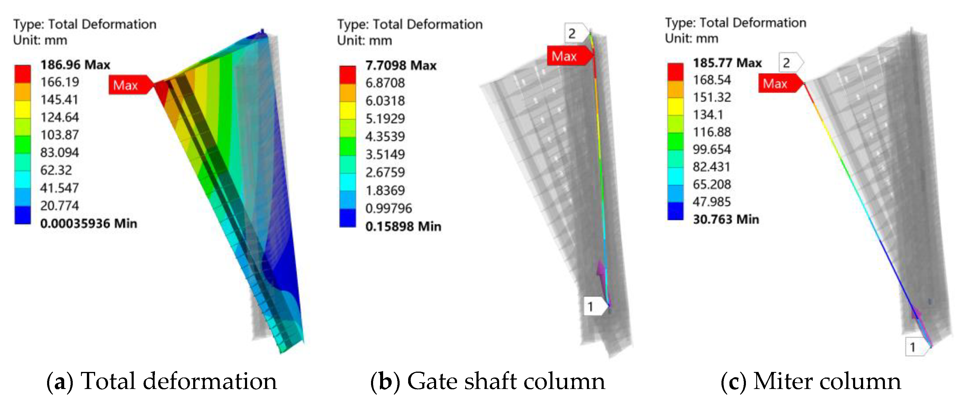
| No back tie rod | 186.96 | 2.8475 | −6.639 | −2.881 | 7.7098 | 2.9945 | 183.19 | −30.752 | 185.77 |
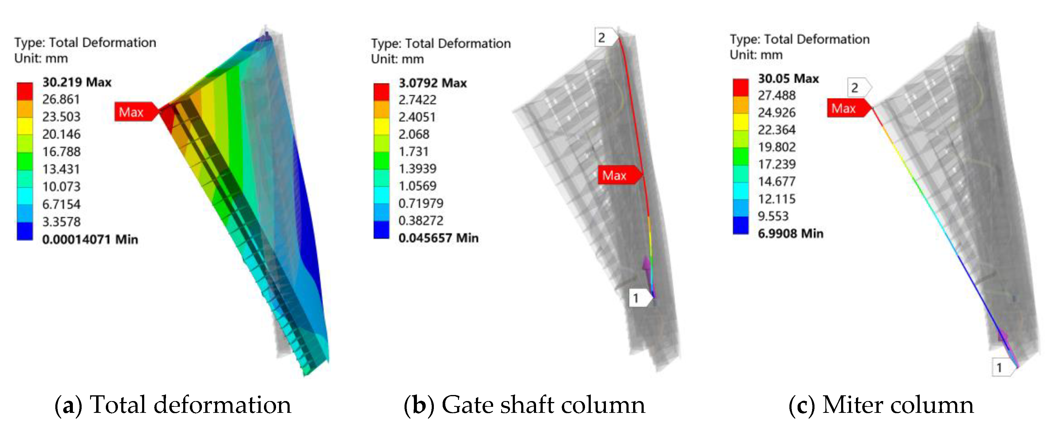
| Back tie rod | 30.219 | −0.549 | −2.333 | −2.825 | 3.0792 | −0.501 | 29.231 | −6.9884 | 30.05 |
| Back Tie Rod Setting Situation | Total Gate Deformation | Door Shaft Post | |||
|---|---|---|---|---|---|
| X Direction | Y Direction | Z Direction | Total Deformation | ||
| Backless tie rod | 276.3 | −13.533 | 275.21 | 43.005 | 275.81 |
| With back rod | 266.71 | −12.431 | 265.7 | 40.136 | 266.23 |
| Back Tie Rod Setting Situation | Total Gate Deformation | Door Shaft Post | Miter Post | ||||||
|---|---|---|---|---|---|---|---|---|---|
| X Direction | Y Direction | Z Direction | Total Deformation | X Direction | Y Direction | Z Direction | Total Deformation | ||
| Backless tie rod | 730.46 | 14.704 | −34.949 | −5.1192 | 37.922 | 16.635 | 720.89 | 76.159 | 725.07 |
| With back rod | 330.58 | 6.3417 | −14.677 | −3.7689 | 15.998 | 6.4437 | 326.8 | 29.318 | 328.13 |
| Back Tie Rod Setting Situation | Total Gate Deformation | Door Shaft Post | Miter Post | ||||||
|---|---|---|---|---|---|---|---|---|---|
| X Direction | Y Direction | Z Direction | Total Deformation | X Direction | Y Direction | Z Direction | Total Deformation | ||
| Backless tie rod | 1032.9 | −21.248 | 48.881 | −1.0649 | 53.3 | −23.458 | −1018.8 | −114.52 | 1025.4 |
| With back rod | 455.73 | −9.2346 | 19.779 | −1.26 | 21.828 | −9.1849 | −449.96 | −46.911 | 452.42 |
Publisher’s Note: MDPI stays neutral with regard to jurisdictional claims in published maps and institutional affiliations. |
© 2022 by the authors. Licensee MDPI, Basel, Switzerland. This article is an open access article distributed under the terms and conditions of the Creative Commons Attribution (CC BY) license (https://creativecommons.org/licenses/by/4.0/).
Share and Cite
Li, R.; Xiao, H.; Xiao, X.; Zhang, J.; Pan, L. Torsional Deformation Analysis of Large Miter Gate under Different Operating Conditions. Energies 2022, 15, 978. https://doi.org/10.3390/en15030978
Li R, Xiao H, Xiao X, Zhang J, Pan L. Torsional Deformation Analysis of Large Miter Gate under Different Operating Conditions. Energies. 2022; 15(3):978. https://doi.org/10.3390/en15030978
Chicago/Turabian StyleLi, Ran, Hanbin Xiao, Xinyi Xiao, Jie Zhang, and Lin Pan. 2022. "Torsional Deformation Analysis of Large Miter Gate under Different Operating Conditions" Energies 15, no. 3: 978. https://doi.org/10.3390/en15030978
APA StyleLi, R., Xiao, H., Xiao, X., Zhang, J., & Pan, L. (2022). Torsional Deformation Analysis of Large Miter Gate under Different Operating Conditions. Energies, 15(3), 978. https://doi.org/10.3390/en15030978